Abstract
Friction has a significant impact on chip formation, so modeling it accurately is crucial in numerical cutting simulations. However, there is still controversy regarding the application scope and effectiveness of various friction models. A two-dimensional orthogonal cutting thermomechanical coupled finite element model is established. Critical strain values, recrystallization temperature, and recrystallization flow stress are introduced, and a power-law-modified softening coefficient is used to modify the standard Johnson–Cook constitutive model to simulate material mechanical properties. Zorev’s friction model, velocity-dependent friction model, and temperature-dependent friction model are separately employed to describe the friction behavior between the tool and workpiece. The contact and friction characteristics between the workpiece and tool, material damage, and temperature field are evaluated. Predicted cutting forces are compared and analyzed with experimental values. The friction coefficient can adjust the contact length between the tool and chip, the high-temperature range on the tool surface, and the fluctuation of temperature throughout the entire cutting process. The friction coefficient is more sensitive to sliding velocity, and the temperature distribution is more sensitive to the friction model than to different working conditions. Whether by modifying the friction coefficient or maximum friction shear stress, and regardless of whether adding parameters affected by velocity or temperature changes the fluctuation range, period, and local peaks of the cutting force prediction curve, improving the accuracy of predictions within certain working condition ranges to some extent. However, the overall trend of error fluctuations obtained from these friction models is similar, and the accuracy of predictions from these friction models tends to become more inaccurate with increasing cutting thickness.
1. Introduction
Titanium alloys possess a host of virtues [1,2,3], rendering them indispensable in aerospace, chemical, medical, and various other domains. However, their intricate nature renders them notoriously challenging to machine, leading to elevated production costs [4]. This difficulty stems from the chemical property at elevated temperatures [5] and many other reasons related to their physical properties. In response, concerted efforts have been undertaken to enhance the machinability of titanium alloys, driven by the imperative to mitigate manufacturing expenses amid escalating demands for these alloys. Yet, elucidating the intricacies of machining processes, particularly with respect to phenomena like chip removal and the cyclic nature of cutting forces, remains an arduous endeavor, particularly in the context of challenging-to-machine materials such as titanium alloys. Conducting experimental investigations into the characteristics and processes of high-speed titanium alloy machining poses significant logistical and financial challenges, often necessitating prolonged durations and substantial investments. Consequently, finite element simulations of the cutting process have emerged as invaluable tools in the realm of titanium alloy cutting theory and practice. By offering expedited insights while economizing both time and resources, such simulations facilitate the anticipation of high-speed cutting performance, foster deeper comprehension of metallic material deformation processes, and elucidate the intricate interplay of forces at the tool–workpiece interface.
The friction at the tool–chip interface significantly impacts the cutting performance of metals and is a major source of cutting heat. The heat generated by friction increases the cutting temperature, which can lead to the degradation of the workpiece material and accelerate tool wear. Friction affects chip formation and the quality of the machined surface, and changes in friction conditions can result in unstable cutting forces, influencing surface morphology. This is particularly true when cutting materials with low thermal conductivity, such as titanium alloys, where friction exacerbates tool wear. Studying the friction mechanism helps optimize cutting conditions, improving machining efficiency and workpiece quality.
Numerous scholars have delved into the intricacies of tool–chip friction in metal cutting, employing both theoretical frameworks and experimental methodologies. Mane et al. [6] developed a pioneering friction test apparatus to measure key parameters. Their research focused on the Ti-6Al-4V alloy and investigated how friction coefficients and heat partition ratios varied across the tool surface. The study revealed distinct friction coefficient values for sliding and adhesive interactions in titanium alloys. Additionally, finite element models were created and validated using experimental data to predict adhesive friction coefficients and heat partition. The results highlighted the complex relationship between friction coefficients, heat partition ratios, and cutting speeds. Dixit et al. [7] compares bare, textured, and TiN-coated WC–Co tools in dry turning of Ti-6Al-4V. Textured tools performed better at higher depths of cut, while TiN-coated tools excelled at lower speeds. The optimal parameters were Vc = 80 m/min and DoC = 0.25 mm, with flank wear under 300 µm. The findings highlight the role of cutting depth and suggest textured tools offer improved wear resistance and potential for future use. Afzal et al. [8] investigated a novel tool combination for dry drilling of the Ti-6Al-4V alloy, using wiper inserts and stepped inserts. Various wiper insert designs and feed rates were tested to assess tool wear, surface roughness, and hole quality. The results showed that LM geometry with a feed rate of 0.10 mm/rev drilled up to 117 holes with surface roughness between 0.70 and 0.90 μm. SEM analysis revealed scratches at lower feed rates and plastic deformation at higher rates. The study recommends LM geometry for optimal tool life and hole quality. Du et al. [9] have formulated a novel analytical expression linking the friction coefficient to key tool parameters. They combined this formula with finite element simulations and experimental validation, focusing on Ti-6Al-4V high-speed grooving. Their findings underscore the significance of the friction coefficient’s correlation with the materials of both the workpiece and the cutting tool, emphasizing its applicability to specific cutting tools tailored for machining distinct workpiece materials. Ni et al. [10] introduced a refined Johnson–Cook constitutive model based on the Modified Slip Gradient (MSG) framework, along with a revised friction model derived from the Slip–Creep Gradient (SCG) approach. They applied these models to simulate turning processes involving Inconel 718. The outcomes revealed that their proposed cascading correction model effectively optimized tool and process parameters, achieving desired cutting forces, temperatures, and chip morphology through simulation-driven optimization. Liu et al. [11] developed an enhanced stick–slip friction model that fully accounts for the thermo-mechanical coupling effects on the dynamic evolution of cutting temperature during copper ultra-precision diamond cutting. Their research showed that this improved model better described the coexistence of tool–chip interactions and transitions between stick–slip friction states compared to conventional Coulomb friction models. Joo et al. [12] found that the machining performance under cryoMQL conditions is significantly improved compared to when cryogenic cooling or MQL is applied separately.
In the realm of finite element modeling, the most straightforward approach often involves employing a constant coefficient Coulomb friction model. This model, readily available in various commercial software suites, offers ease of implementation and has found widespread adoption among scholars. While refinements to this model, such as the integration of velocity-dependent terms like the exponential Coulomb model, are possible, the inherent variability of friction coefficients across different workpiece materials, tool configurations, and attributes such as geometry and coatings poses a significant challenge. Thus, the precise determination of friction coefficients tailored to specific materials and tool types often necessitates extensive experimental exploration under carefully controlled cutting conditions.
Mohammed et al. [13] found that the instantaneous heating effect before cutting has a relatively minor influence on machining performance. Notably, the model pioneered by Zorev et al. [14], which has garnered widespread adoption by researchers [15,16,17,18,19], delineates the frictional domain into discrete segments comprising sliding and adhesive friction regions. Herein, the sliding friction regime adheres to the Coulomb friction model, whereas the adhesive friction realm relies on constant frictional shear stress. The identification and differentiation between these adhesive and sliding friction domains typically entail algorithmic implementations. Additionally, alternate friction models [20] exist that exhibit dependencies on factors such as temperature or cutting speed. Phenomenological constitutive models serve as vital tools in capturing the intricate macroscopic behaviors. Among these models, the Johnson–Cook (J-C) model [21] and the Khan Liu (KHL) model [22] stand out as the most prevalent choices for simulating metal cutting operations. The J-C model, characterized by its simplicity and inclusion of terms for strain, strain rate, and temperature, offers a pragmatic approach appreciated for its ease of implementation and reasonably accurate representation of metal cutting dynamics. In a recent development by Avevor and colleagues [15], a novel model integrating the Arbitrary Lagrangian–Eulerian (ALE) method with tool translation was proposed, extending the application of ALE techniques to milling processes. In a complementary effort, Kumar et al. [23] undertook the task of establishing a fracture energy-based damage evolution finite element model, utilizing the J-C constitutive model within Abaqus/Explicit software (V6.14). Their meticulous validation through experimental validation highlighted the efficacy of adding TiAlCrN coatings in reducing tool friction and moderating temperatures. Aridhi et al. [24] compares the application of CEL and ALE methods in the orthogonal cutting process, aiming to assess the accuracy of predicting physical quantities (such as forces and chips), and to analyze the time required for the simulation. The results show that the quantitative results from both ALE and CEL methods are very similar and closely match experimental values. The ALE method has a shorter computation time, while the CEL method is more convenient and stable in simulation preparation. However, the ALE method requires multiple trials to adjust the initial conditions. Overall, the CEL method is more reliable for automating multiple simulations, making it the preferred choice. Dumanić et al. [25] used the Coupled Eulerian–Lagrangian (CEL) method for finite element simulation, and explores the material and damage models. The results show that the optimal parameter combination significantly reduced the cutting force and feed force errors and shortened simulation time. Additionally, the CEL method successfully predicted the temperature in the cutting zone.
However, the standard J-C model struggles to capture the nuanced flow behavior and softening effects of materials at high strain rates, thereby limiting its ability to unveil the intricacies of serrated chip formation mechanisms. This model relies on several undetermined parameters linked to material properties, whose values exert significant influence on computational outcomes. Consequently, researchers [26,27,28] often undertake the meticulous task of selecting and testing parameters.
Hence, many scholars opt to complement the standard J-C model with relevant physical principles, striving for a comprehensive understanding of material flow behavior and chip formation mechanisms, thus achieving precise characterization of the mechanical response of workpiece materials during machining.
Liu et al. [29] improved the Johnson–Cook (J-C) constitutive model for high-speed cutting simulations of the Ti-6Al-4V alloy by incorporating recrystallization effects. The model parameters were fitted using flow stress–strain data from Split Hopkinson Pressure Bar (SHPB) tests. Simulation results revealed that the improved model showed a 46.7% stress drop when temperature increased from 950 °C to 1000 °C, compared to just a 10% decrease with the J-C model. The improved model more accurately predicts stress variations under high-temperature and heavy-load conditions in high-speed milling. Zhu et al. [30] developed a constitutive model combining plasticity and damage components. The model outperformed the J-C model in predicting chip morphology and cutting forces, revealing two distinct chip formation mechanisms in simulations and experiments. Lei et al. [31] introduced an innovative approach to computational mechanics constitutive modeling, incorporating the intricate interplay between dislocations and crystal defects. Through mathematical modeling, they characterized the evolution of dislocation density and grain size in polycrystalline metal materials under strain, subsequently analyzing their distinct impacts on material strength. This meticulous analysis led to the derivation of computational mechanics constitutive relations, which were effectively validated against experimental stress–strain relationships for a range of alloys including Cu, Al-Mg, and Cu-W. Lei et al. [31] developed a computational mechanics model incorporating dislocations and crystal defects to analyze dislocation density and grain size evolution in polycrystalline metals. The model, validated against experimental stress–strain data, accurately predicted material strength for alloys.
Physics-based constitutive models, rooted in the intricate thermal activation mechanisms of dislocations, delve deeply into the microscopic dynamics of material behavior. Pioneering research by Johnson et al. [32] has shed light on the pivotal role played by interstitial content in determining the yield stress of materials. In the realm of high-speed machining, the profound interplay between thermal and mechanical forces can instigate a profound evolution of microstructural features within the workpiece deformation zone. This transformative process may lead to grain refinement, exerting a profound influence not only on mechanical properties but also on the fatigue resistance and corrosion resilience of machined surfaces. Titanium alloy Ti-6Al-4V presents a fascinating case, characterized by two distinct crystal structures: the densely packed hexagonal α phase and the body-centered cubic β phase. As the cutting process unfolds, the rising temperature prompts a gradual transition of the α phase into the β phase, culminating in a critical temperature indicative of complete α phase transformation. Ullah et al. [33] developed a finite element model for high-speed milling of Ti-6Al-4V, incorporating Zener–Holloman and Hall–Petch equations to simulate dynamic recrystallization effects. The model predicted grain size and microhardness changes, validated by experimental data, revealing insights into microstructural evolution and mechanical performance during machining. Liu et al. [34] studied grain refinement in shear bands of Ti-6Al-4V during machining, finding continuous dynamic recrystallization (CDRX) instead of the typical discontinuous dynamic recrystallization (DDRX). A CDRX model was proposed and validated through FE and CA simulations, analyzing microstructure evolution.
In this study, a modified J-C model is used to more accurately simulate Ti-6Al-4V deformation, incorporating parameters like recrystallization flow stress and temperature. The study evaluates the Zorev, velocity-dependent, and temperature-dependent friction models through thermomechanically coupled simulations. By comparing results with experimental data, the study assesses the adaptability and precision of these models. The findings enhance understanding of frictional dynamics, aiding in refining simulation processes and determining optimal friction model applications for titanium alloy machining.
2. Modelling and Simulation
2.1. Orthogonal Cutting Model
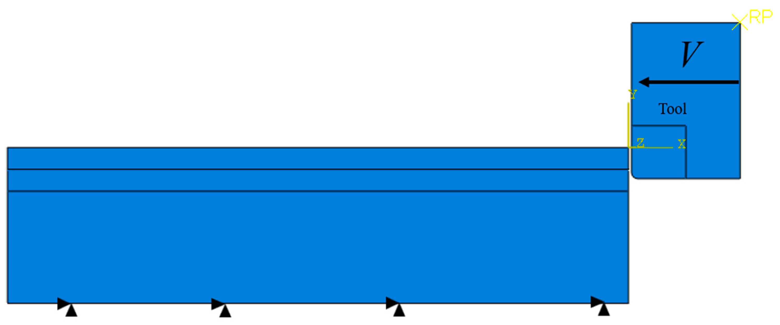
Owing to the adoption of constitutive and friction models, along with the imperative of ensuring computational precision, the mesh size has been reduced, albeit at the expense of increased computational expense. To facilitate seamless computation, the workpiece has been partitioned into three distinct regions [16]. The chip layer boasts a thickness of 100 μm units, the damage layer 60 μm units, and the base layer 340 μm units. These parameters remain invariant across various cutting thickness scenarios and are governed by the same constitutive model. As per experimental findings [35], the tool possesses front and back angles of 0°.
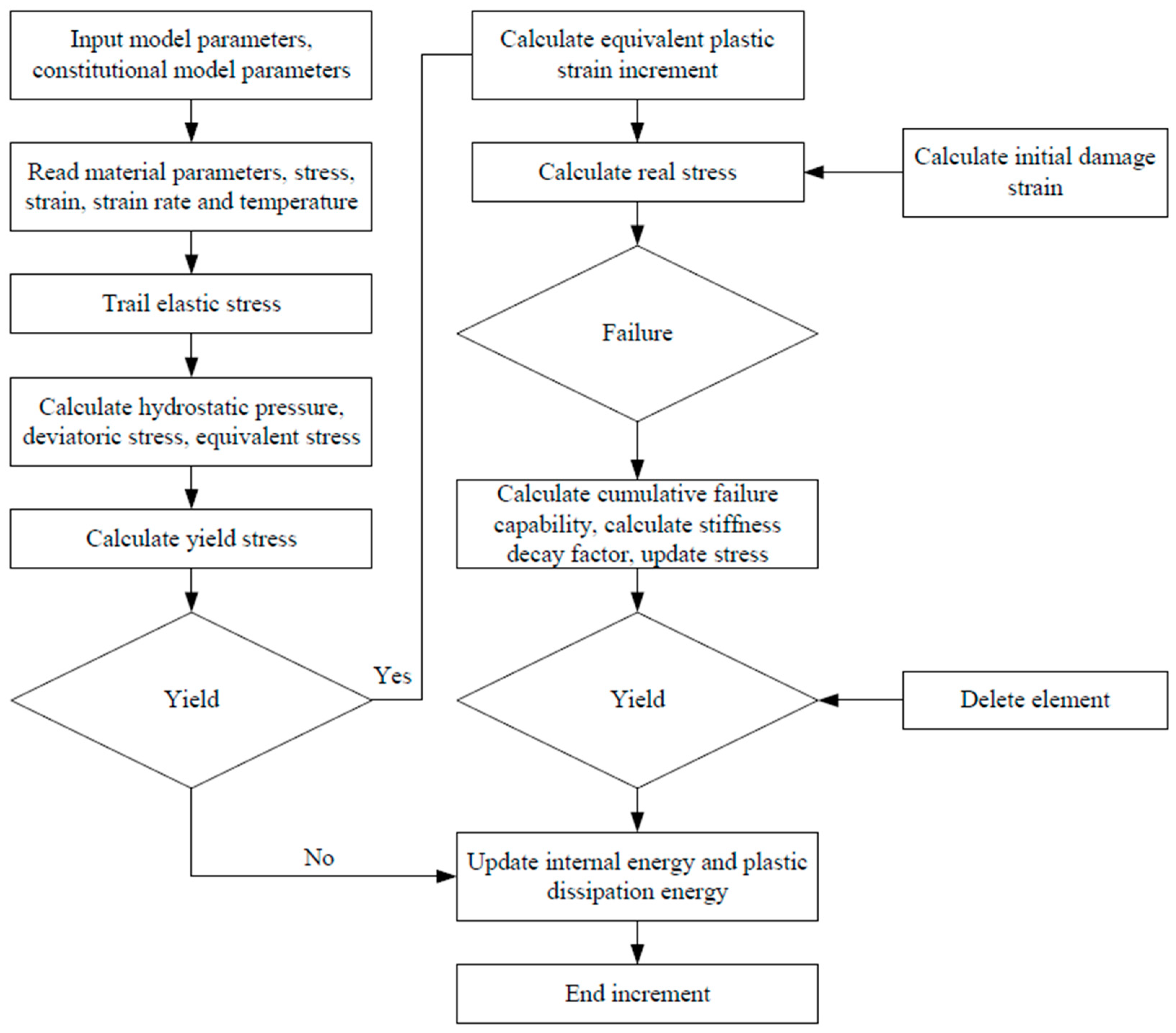
The specific cutting conditions employed for the simulation are outlined in Table 1. A flowchart of the calculation is given in Figure 1. The geometric configurations of the model are depicted in Figure 2. The choice of PCBN as the tool material entails treating it as a rigid body during modeling. Notably, the mesh size of the tool plays a pivotal role in shaping the formation of serrated chips [16], prompting the utilization of a meticulously refined mesh. Employing CPE4RT four-node coupled thermal plane strain quadrilateral elements with bilinear displacement and temperature, reduced integration, and hourglass control, mesh division is meticulously executed. Near the workpiece, the mesh is densely populated with a grid size of 5 units, while it transitions to a sparser arrangement, with a grid size of 10 units, further from the cutting area. This meticulous mesh refinement strategy yields a total of 4047 elements and 4133 nodes. Ensuring a finely tuned mesh is imperative to capture the intricate formation process of serrated chips; thus, the chip region of the workpiece and the damage layer are endowed with a quadrilateral structure mesh, each with a grid size of 5 units. Similarly, the base layer adopts this quadrilateral structure mesh approach with a grid size of 5, enhancing both computational precision and convergence. Extensive computational trials underscore the significance of refining the base layer mesh to ensure computational convergence. Despite the computational overhead, maintaining consistency with the workpiece’s mesh size aids in facilitating convergence. The workpiece, meanwhile, is subjected to mesh partitioning utilizing CPE4RT four-node coupled thermal plane strain quadrilateral elements with bilinear displacement and temperature, reduced integration, and hourglass control, culminating in 30,000 elements and 30,401 nodes.

Table 1.
Cutting conditions of the experiments.
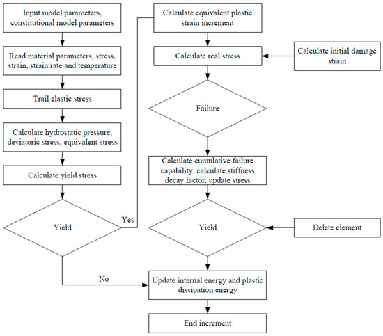
Figure 1.
Flowchart of calculation.

Figure 2.
Orthogonal cutting model.
2.2. Constitutive Model
The classical Johnson–Cook (J-C) model, used for simulating Ti-6Al-4V behavior, considers strain, strain rate, and temperature but lacks the ability to account for recrystallization during adiabatic shear. Microstructure evolution, influenced by dislocation density, grain deformation, and nucleation, affects mechanical properties. This highlights the need to refine the J-C model to better predict microstructural changes during high-strain machining of titanium alloys. The J-C constitutive model is as follows:
where is the yield strength, the equivalent plastic strain, the equivalent plastic strain, the strain hardening exponent, the strain hardening parameter, the equivalent plastic strain rate, the reference strain rate, the current temperature, is the melting temperature, is the room temperature and the thermal softening coefficient. Some physical properties of the Ti-6Al-4V material are shown in Table 2. The J-C model parameters are listed in Table 3.
Table 2.
Material properties of the workpiece.
Table 3.
Material parameters of modified J-C model.
The conventional J-C model has limitations in high-speed cutting scenarios, affecting chip formation, temperature, and cutting force predictions. Titanium alloys experience significant plastic deformation at high temperatures and strain rates. Refining the J-C model is crucial to accurately capture dynamic material behavior and predict cutting forces and serration characteristics. The modified J-C constitutive model is as follows [16]:
where is the recrystallization temperature, is flow stress before recrystallization and is flow stress after recrystallization. is the floor function. The model parameters are as shown in Table 3.
2.3. Damage Model
In the deformation process induced by compression, the workpiece material undergoes deformation, with a portion of it separating from the base material to form chips. Generally, adopting physical criteria makes the simulated cutting scenario closer to reality, and the results of physical quantities such as force and heat simulated are more accurate. The parameters used to determine failure are specified as follows:
where is the increment of equivalent plastic strain, and is the critical equivalent plastic strain [36].
Coefficients of the J-C damage model of Ti-6Al-4V are as shown in Table 4. Components of Ti-6Al-4V are as shown in Table 5.
Table 4.
Coefficients of the J-C damage model of Ti-6Al-4V.
Table 5.
Components of Ti-6Al-4V.
The damage evolution [37] is expressed by the following equation:
where is the equivalent plastic displacement during the material failure process, stands for the equivalent plastic displacement at complete material failure, and denotes the characteristic length of the element. The stiffness degradation is given by the following equation:
where is the equivalent plastic displacement, is the stress matrix, and is the stiffness factor.
2.4. Tool–Chip Friction Model
2.4.1. Contact Modelling
In the cutting simulation, the tool interacts with both chips and base material. To speed up calculations, the tool’s travel distance is kept short, and no contact occurs between chips and base material. A penalty contact approach is used, with automatic penalty stiffness selection to minimize contact penetration. The tool is treated as a rigid body, with master and slave surfaces designated for contact. Friction varies tangentially across different tool regions.
2.4.2. Zorev’s Friction Model
The Coulomb friction model represents a conceptual framework used to explain the frictional interaction between surfaces in motion relative to each other. At its core, this model posits that friction arises from the interplay of microscopic irregularities present on these surfaces. According to Coulomb’s model, the frictional force between the surfaces predominantly arises from the interaction of distinct types of forces. A pivotal aspect of the Coulomb friction model is its assertion that frictional force varies directly with the normal pressure, which refers to the vertical pressure exerted between the surfaces. This signifies that augmenting the normal pressure will escalate the frictional force, while diminishing the normal pressure will reduce it. The standard Coulomb friction model assumes that no relative motion occurs if the equivalent frictional stress is less than the critical stress, which is proportional to the contact pressure. Coulomb’s friction law is formulated as follows:
The friction model built into Abaqus software (V6.14) is the Coulomb friction model, and the software provides model parameters that can be adjusted.
It is important to recognize that the Coulomb friction model offers a simplified perspective, overlooking certain factors like surface chemistry and temperature that can influence friction. Therefore, practical applications may necessitate more intricate models to accurately capture friction phenomena. Tool wear during machining is significantly impacted by friction at the tool–chip interface. The interplay between local stress, velocity, and temperature conditions determines the sliding–sticking zone at this interface. Friction between the tool and workpiece is contingent upon the workpiece material type and various interrelated factors. Past research underscores that friction during material removal is contingent upon temperature and the interplay of surface properties, along with operational parameters such as cutting speed, depth, and feed rate, lubrication, tool material composition, geometry, and workpiece material. Despite the complexity of these interconnected variables, a thorough comprehension of the tribological behavior involved is paramount for machining success [38,39,40]. The frictional stress is articulated as follows [41]:
2.4.3. Velocity-Dependent Friction Model
Afrasiabi et al. [20] introduced an innovative method to measure the leading edge temperature in orthogonal metal cutting without disturbing chip flow, providing data to validate thermal predictions in chip formation simulations with greater accuracy. By applying inverse parameter identification techniques, they proposed new temperature- and velocity-dependent friction coefficients for AISI 1045 and Ti-6Al-4V under cutting conditions. Internal experimental measurements were used to determine flow stress and friction parameters, ensuring a more consistent set of input parameters for SPH and FEM simulations. The coefficients proposed by Afrasiabi are as follows:
These modified friction coefficients will be involved in the calculations of this paper to represent the velocity-dependent friction model.
2.4.4. Temperature Dependent Friction Model
Zorev’s framework reveals a nuanced friction mechanism in cutting, diverging from conventional Coulomb friction. While widely utilized in cutting simulations, it overlooks temperature effects and inter-parameter correlations. Many researchers simplify this model during application. Firstly, there is an absence of a standardized limit shear stress value; often, it is simplified to the material’s shear yield strength at room temperature, disregarding its temperature-dependent nature during cutting. Secondly, assuming a constant friction coefficient overlooks its variability with temperature, pressure, and sliding speed. Lastly, the relationship between the limit shear stress and the friction coefficient remains unexplored. Fu et al. [42] rectified Zorev’s model through experiments, the model is given as follows:
These modified friction coefficients will be involved in the calculations of this paper to represent the temperature-dependent friction model.
3. Experimental Orthogonal Cutting Tests
A flowchart of the calculation is given in Figure 1. The experimental parameters used in this study are shown in Table 1. This experiment uses TNGA160404-3N-type PCBN inserts produced by Beijing World Company (Beijing, China) and a tool holder of model MTFNR2020X16. The material used for the orthogonal turning experiment is the Ti-6Al-4V titanium alloy bar with a hardness of 338 HV0.025. This study primarily focuses on the development and testing of the model. The forces in the x, y, and z directions were measured using a KISTLER-9257b three-axis piezoelectric quartz dynamometer (Kistler, Vienna, Austria). The sampling frequency was set to 10 kHz to record the cutting force data, which were used for both qualitative and quantitative analysis of static and dynamic cutting forces. The experiments were conducted by He [43].
A vertical milling machine is used as a substitute for a lathe. The workpiece is mounted on the spindle, and the tool is fixed on the worktable using a specific tool holder. High-speed orthogonal turning experiments on Ti-6Al-4V titanium alloy are conducted during the cutting process to ensure the reliability of the experimental results. The parallel movement along the Y-axis allows for the tool’s entry and exit actions, thereby enabling orthogonal turning experiments on the milling machine. Measuring devices such as a force sensor are installed on the worktable. Additionally, the tool holder can strictly control the cutting edge inclination angle at 0° to meet the conditions of orthogonal cutting. Cutting experiments on Ti-6Al-4V titanium alloy bars are carried out under different cutting parameters, and cutting force data are recorded after each experiment. The tool wear is also observed, and the tool is replaced promptly if wear or chipping occurs, to prevent the tool wear from affecting the experimental results. For detailed information on the measurement methods for cutting forces and temperatures, material hardness, microstructure properties, surface treatment, cutting tool materials and geometries, the use of cutting fluids, and environmental conditions (temperature, humidity), please refer to the reference [43].
4. Results and Discussion
4.1. Results
Figure 3, Figure 4, Figure 5, Figure 6, Figure 7 and Figure 8 present detailed illustrations of the computed results obtained using various friction models. Parameters related to friction contact include contact pressure, shear stress, length of contact slip path and magnitude of contact slip rate. Parameters associated with material characteristics include equivalent plastic strain, scalar stiffness degradation, and temperature. These results serve to analyze the influence of different friction models on the simulation of the cutting process. Additionally, they encompass combinations of various cutting speeds and depths, facilitating an assessment of the performance of friction models under different working conditions.
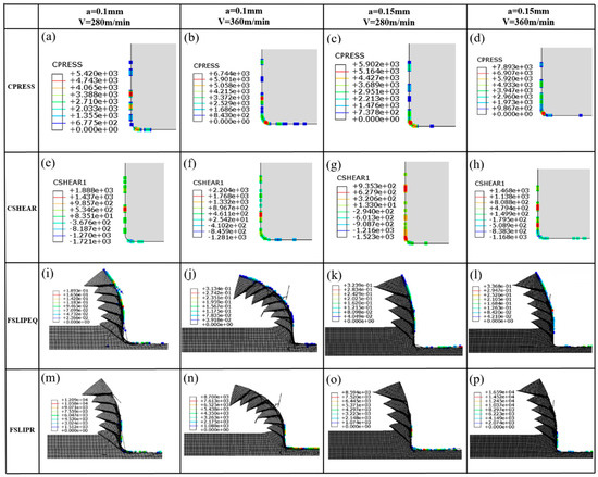
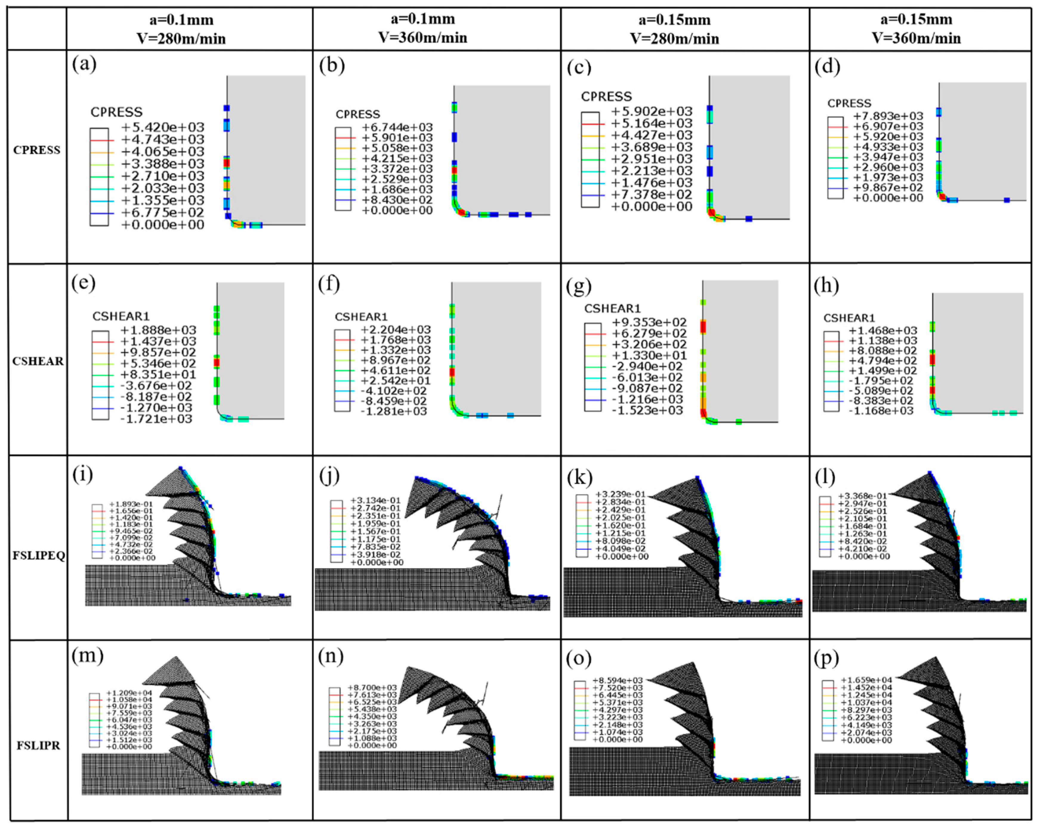
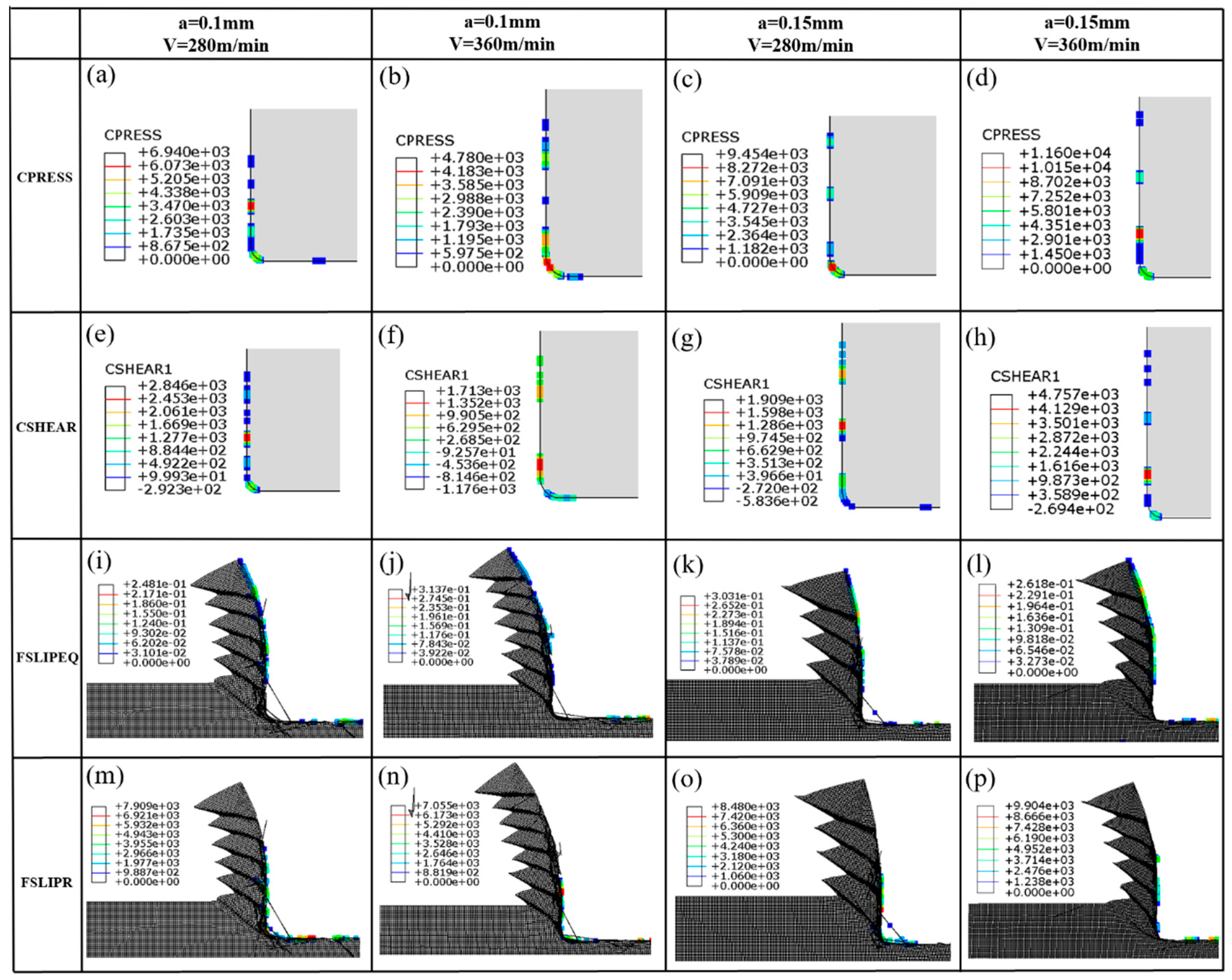
Figure 3.
Friction−related results of temperature–dependent friction model with varied machining conditions. (a–d): Contact pressure under various operating conditions, (e–h): Contact shear stress under various operating conditions, (i–l): Frictional slip equivalent force under various operating conditions, (m–p): Frictional slip ratio under various operating conditions.

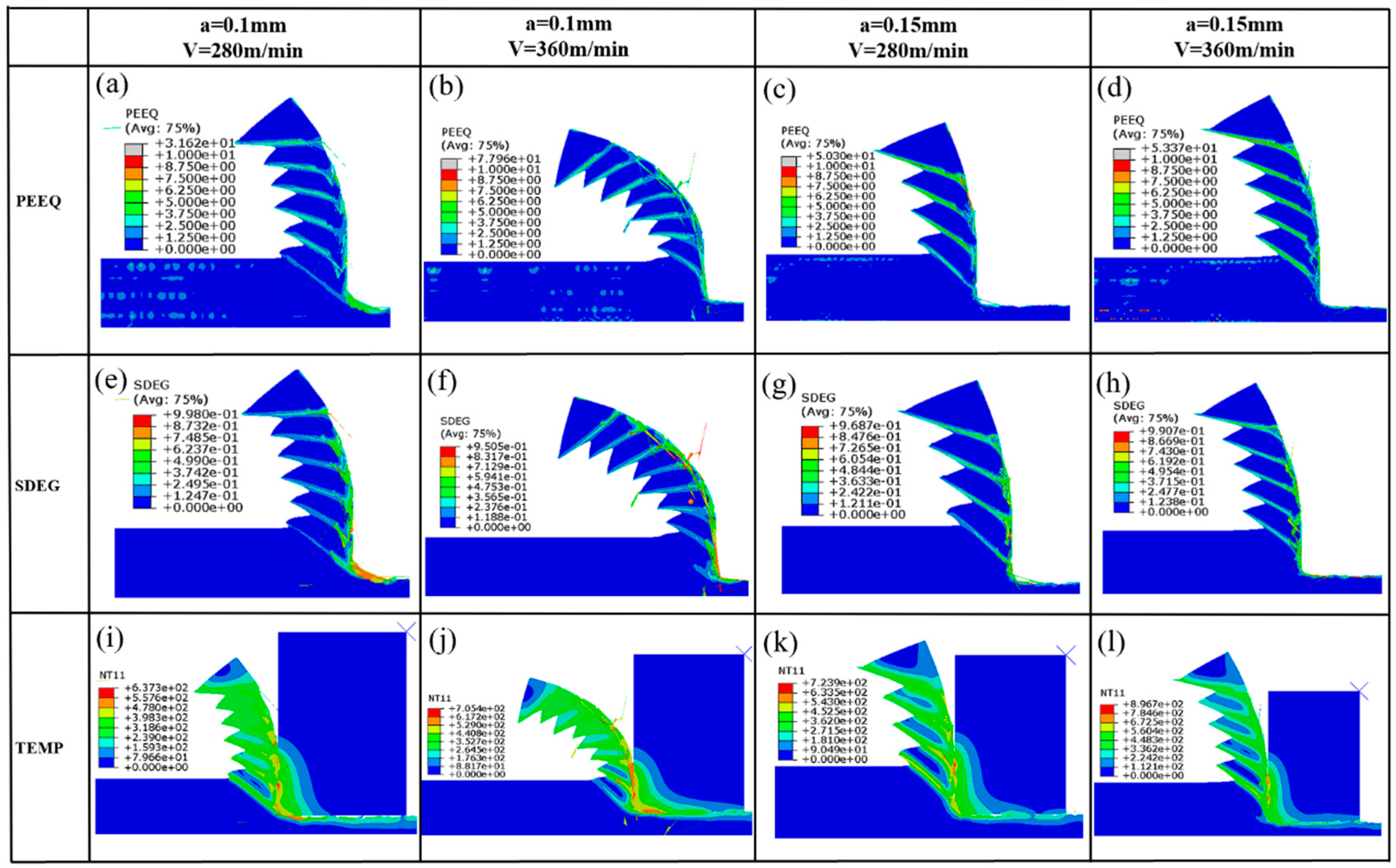
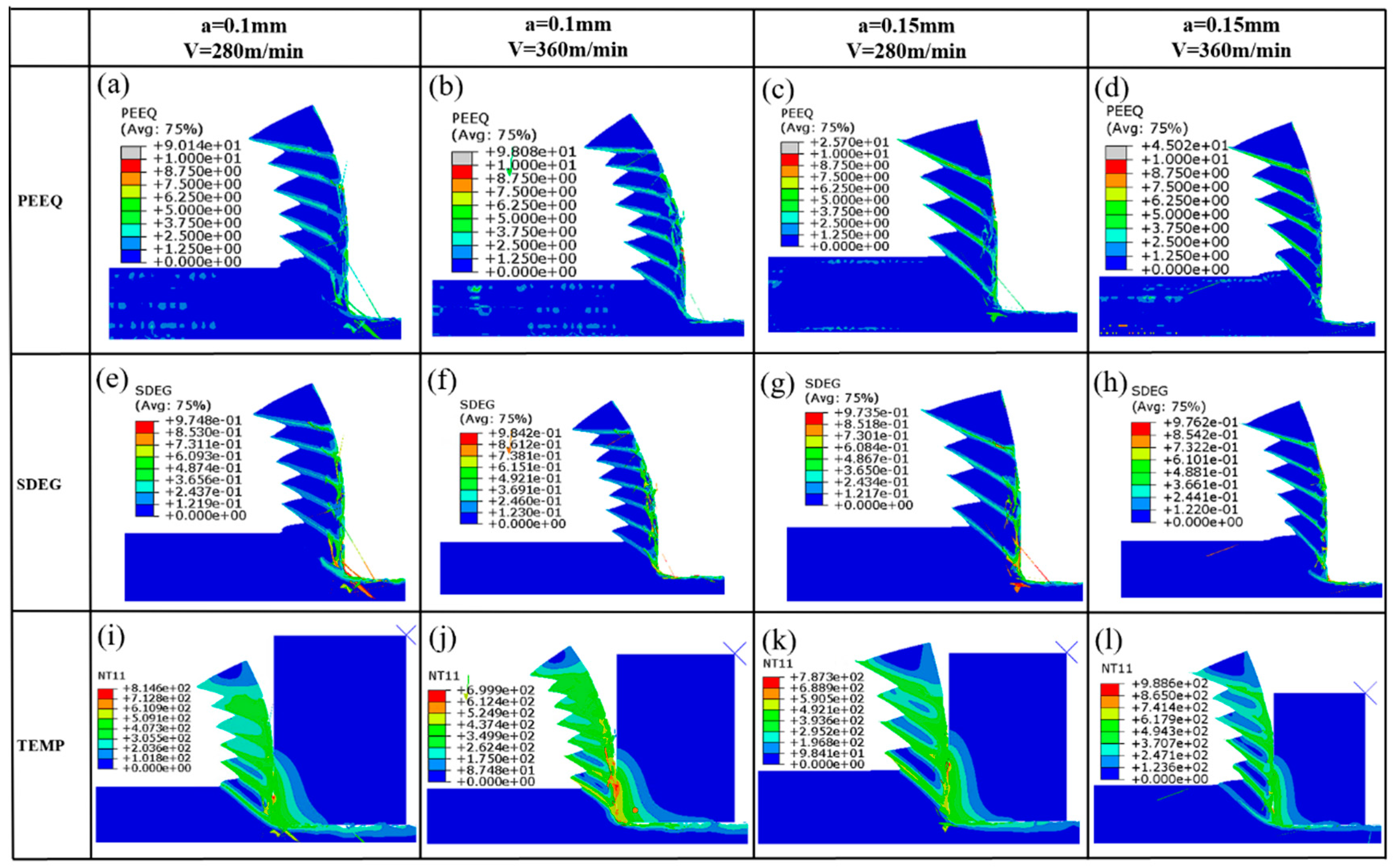
Figure 4.
Simulation results of temperature–dependent friction model with varied machining conditions. (a–d): Equivalent plastic strain under various operating conditions, (e–h): Scalar damage evolution under various operating conditions, (i–l): Node temperature under various operating conditions.
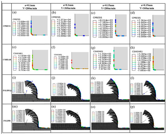
Figure 5.
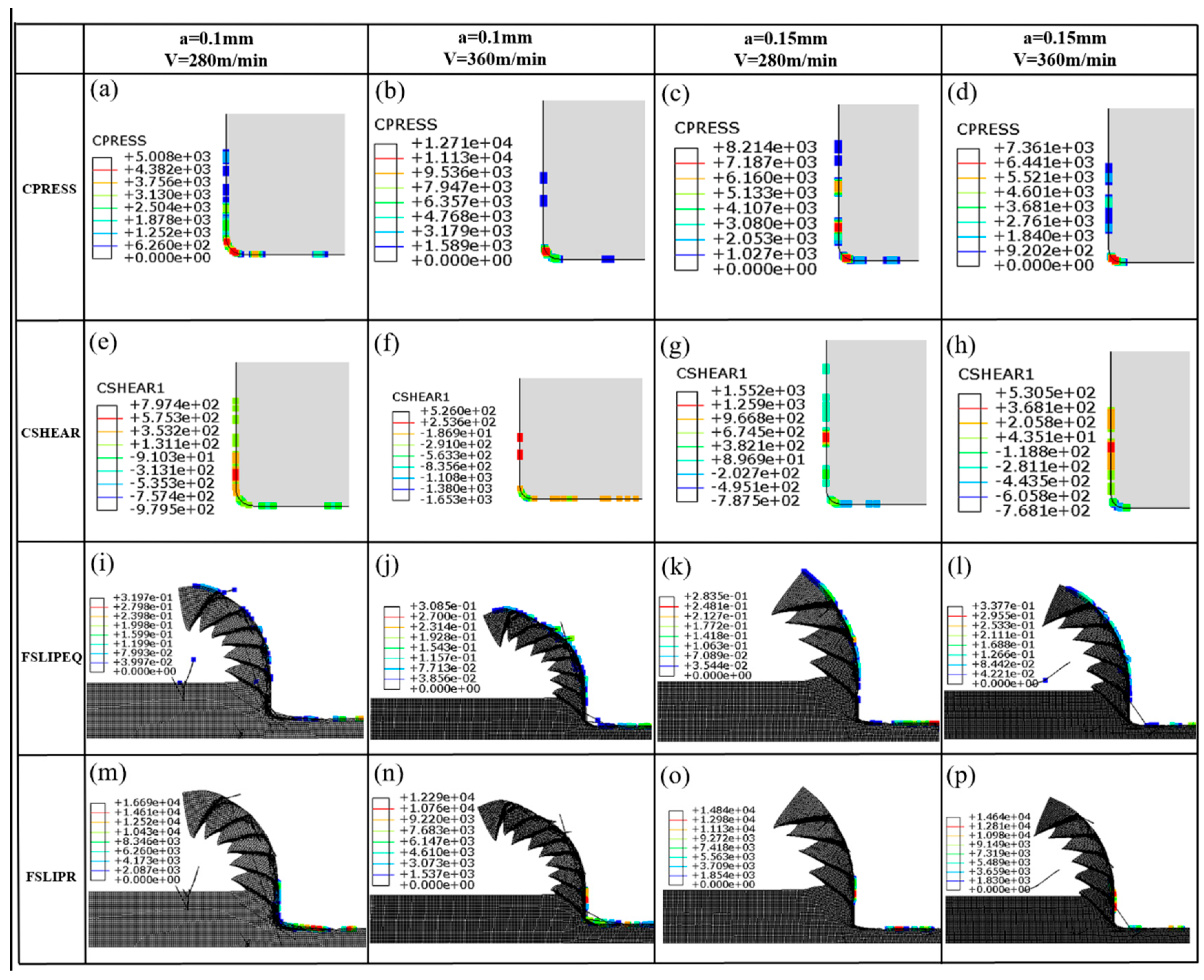
Friction–related results of velocity–dependent friction model with varied machining conditions. (a–d): Contact pressure under various operating conditions, (e–h): Contact shear stress under various operating conditions, (i–l): Frictional slip equivalent force under various operating conditions, (m–p): Frictional slip ratio under various operating conditions.
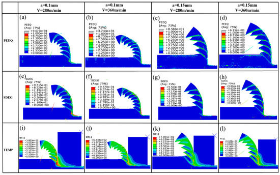
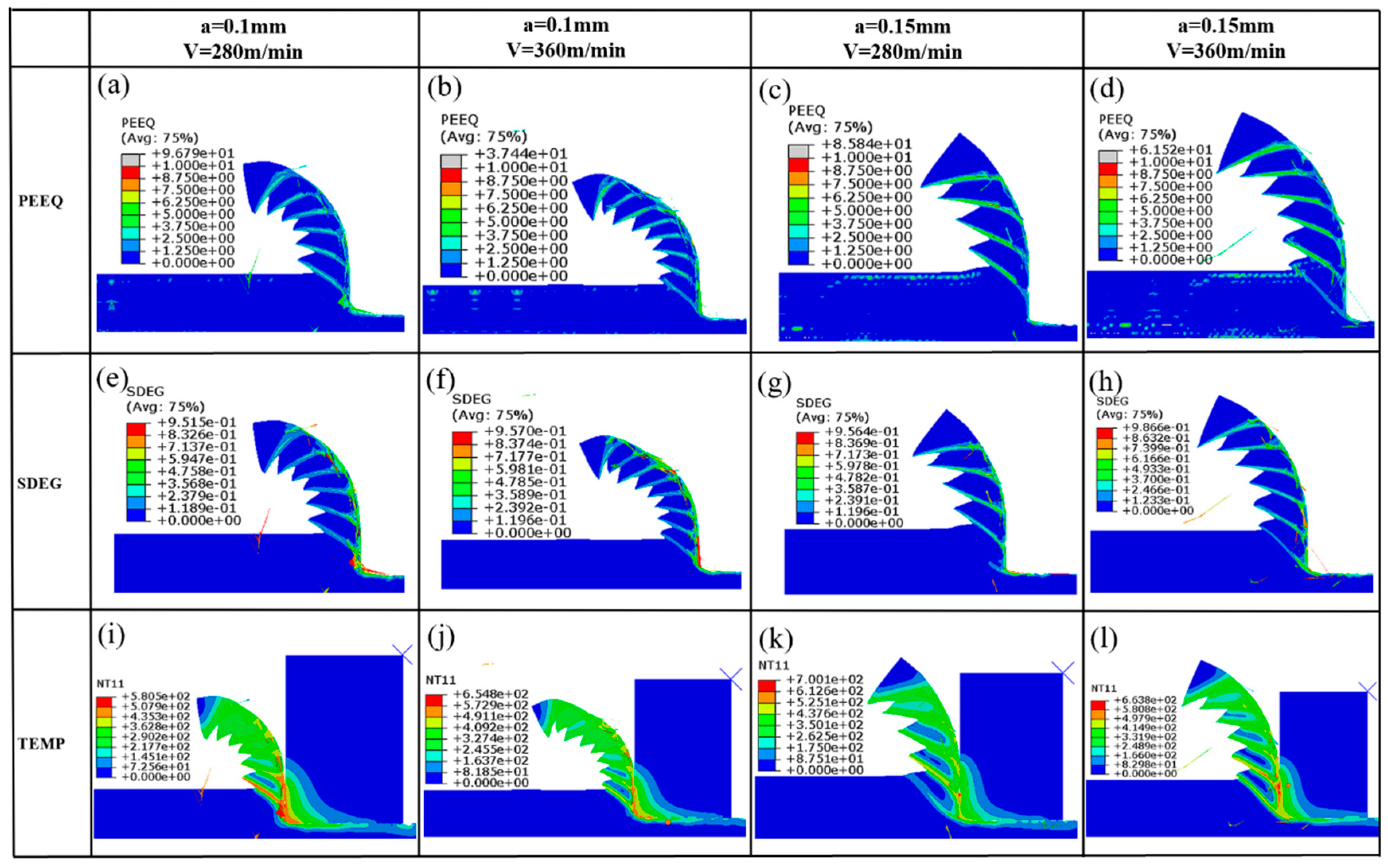
Figure 6.
Simulation results of velocity–dependent friction model with varied machining conditions. (a–d): Equivalent plastic strain under various operating conditions, (e–h): Scalar damage evolution under various operating conditions, (i–l): Node temperature under various operating conditions.

Figure 7.
Friction−related results of Zorev’s friction model with varied machining conditions. (a–d): Contact pressure under various operating conditions, (e–h): Contact shear stress under various operating conditions, (i–l): Frictional slip equivalent force under various operating conditions, (m–p): Frictional slip ratio under various operating conditions.

Figure 8.
Simulation results of Zorev’s friction model with varied machining conditions. (a–d): Equivalent plastic strain under various operating conditions, (e–h): Scalar damage evolution under various operating conditions, (i–l): Node temperature under various operating conditions.
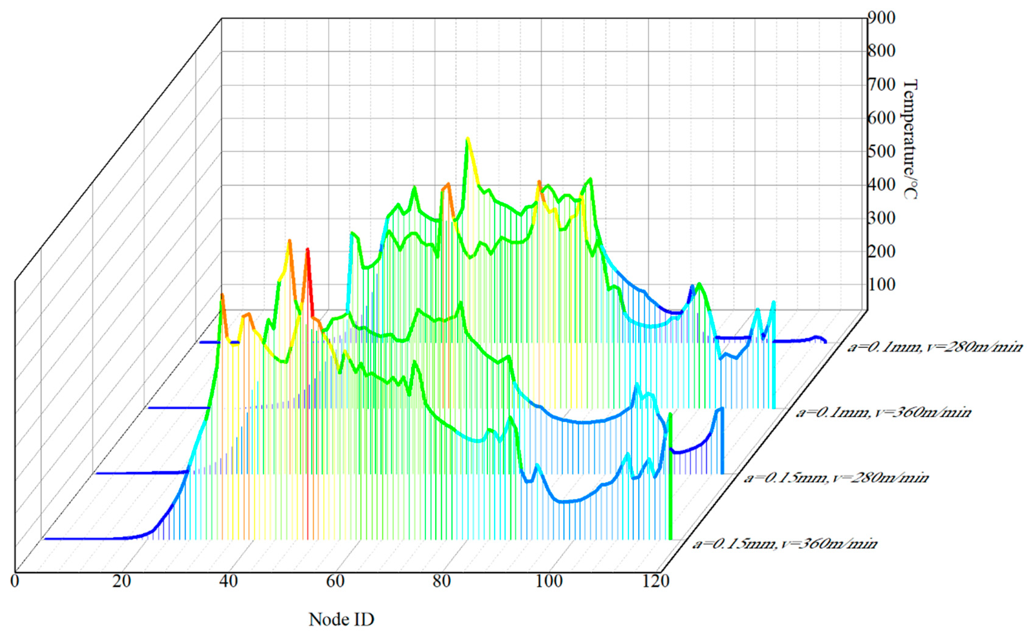
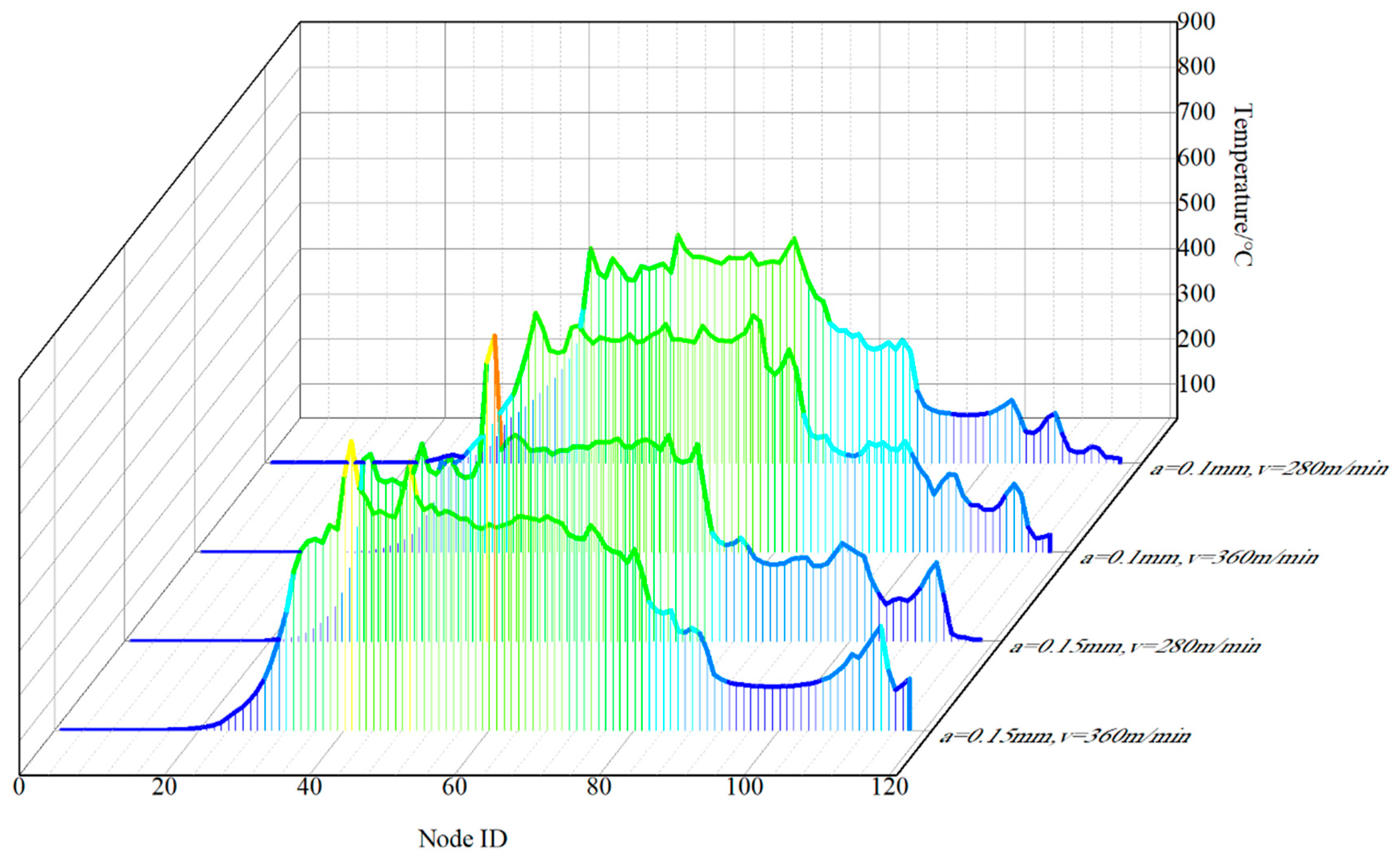
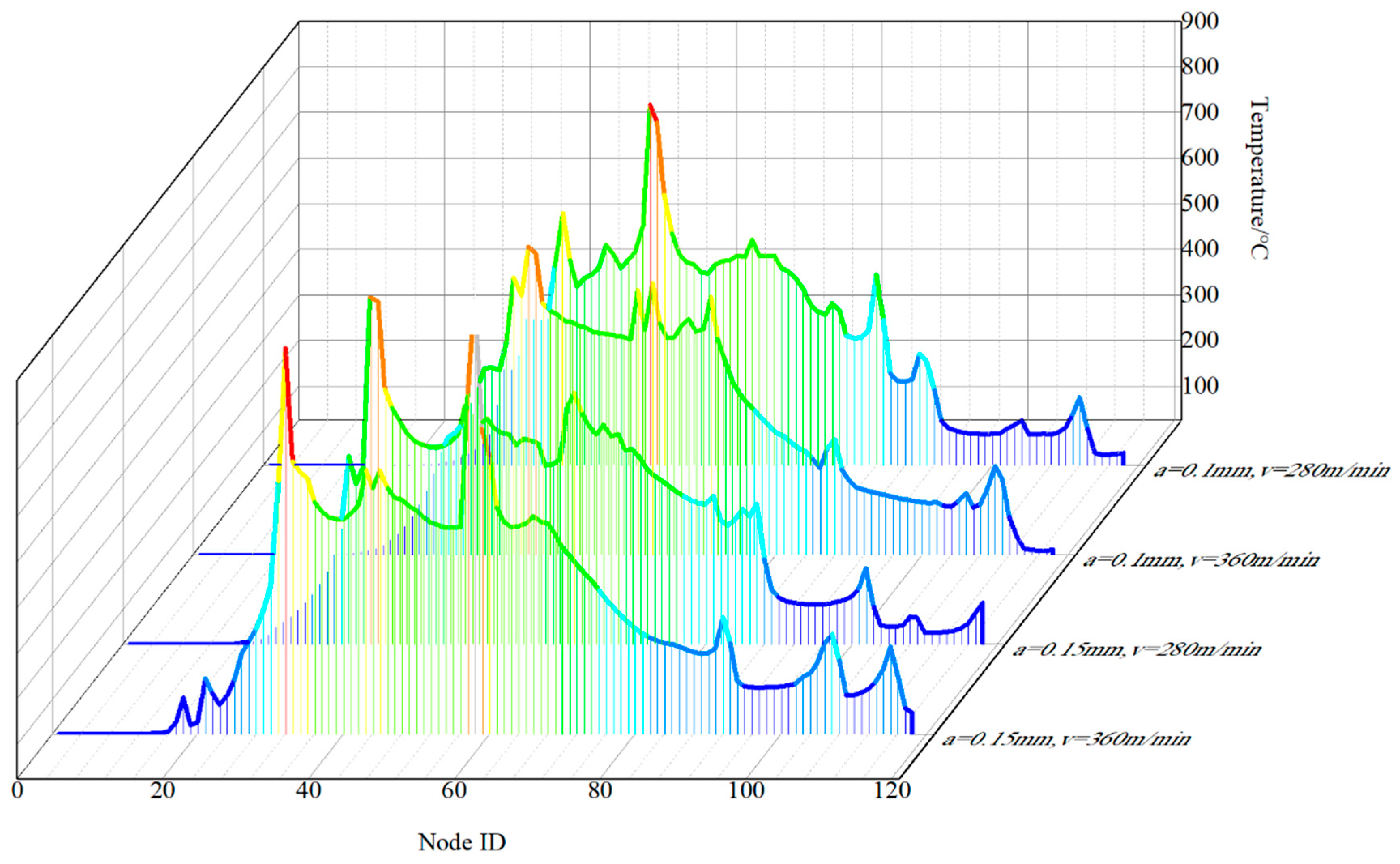
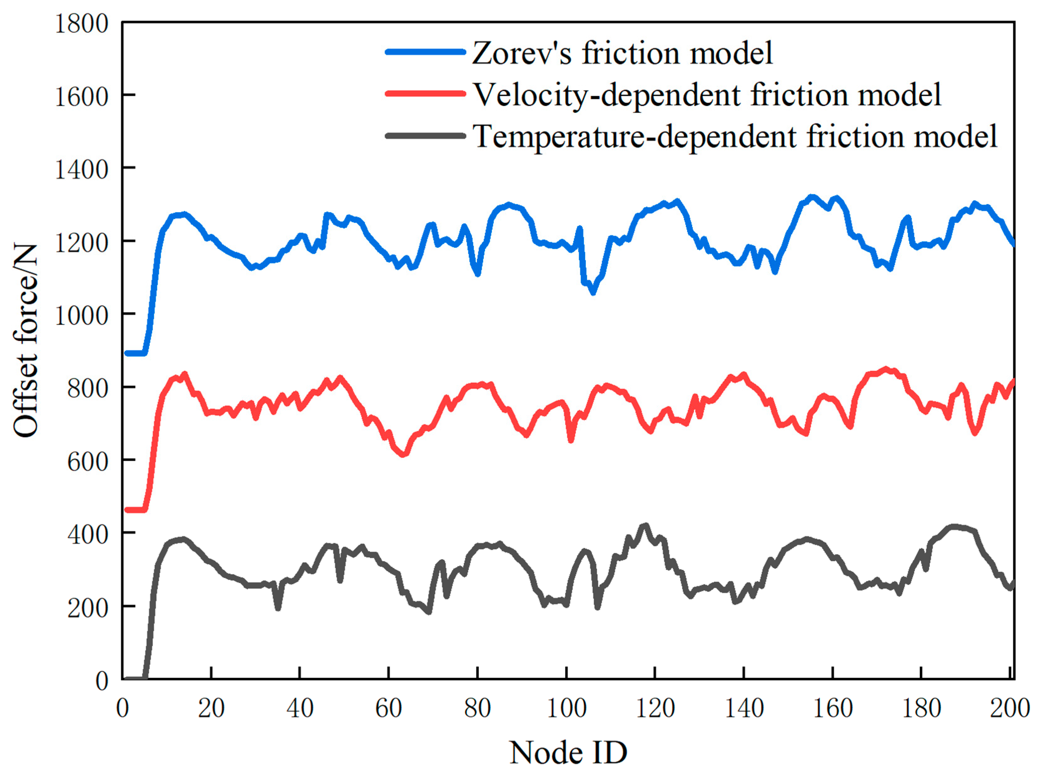
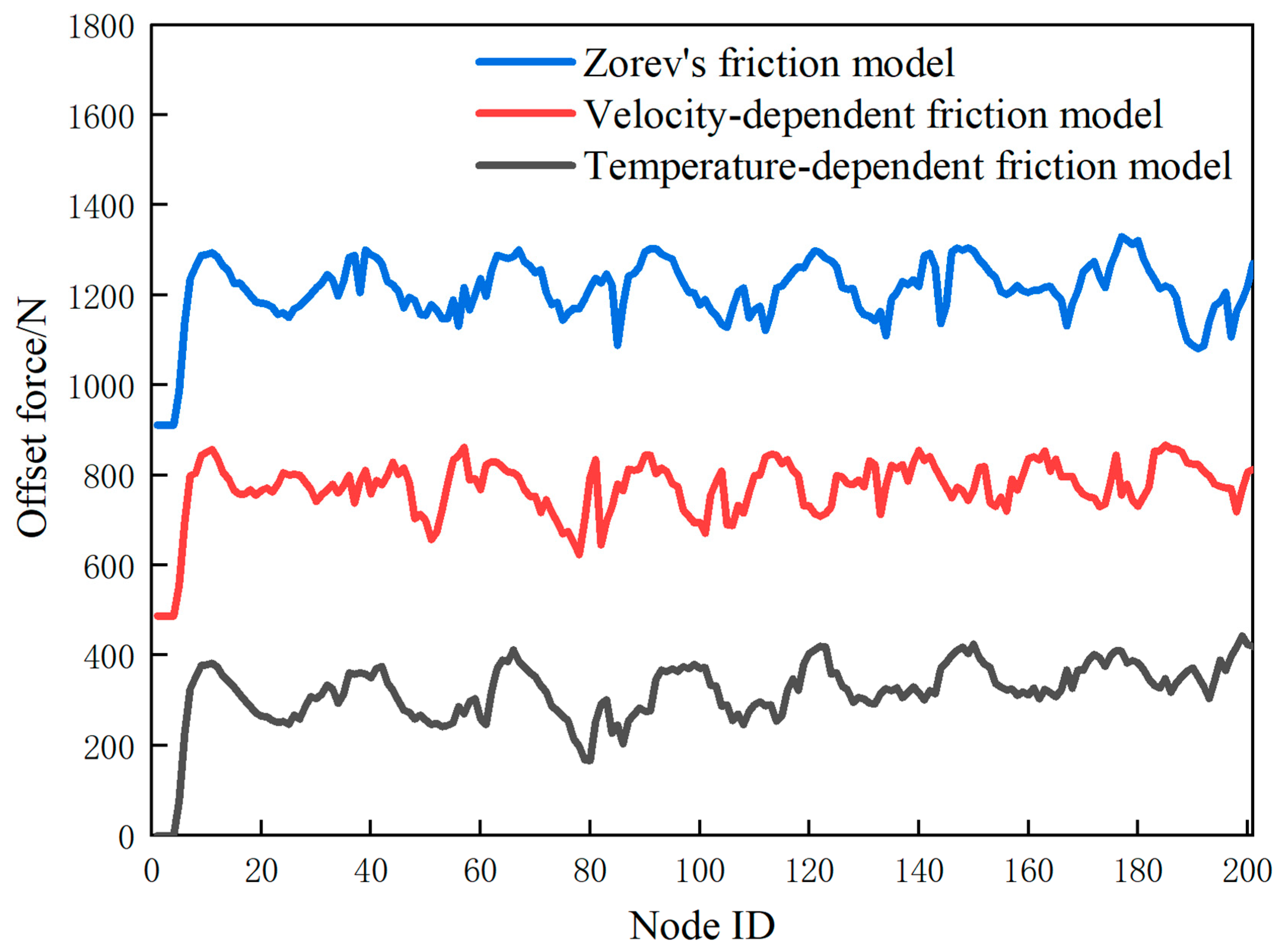
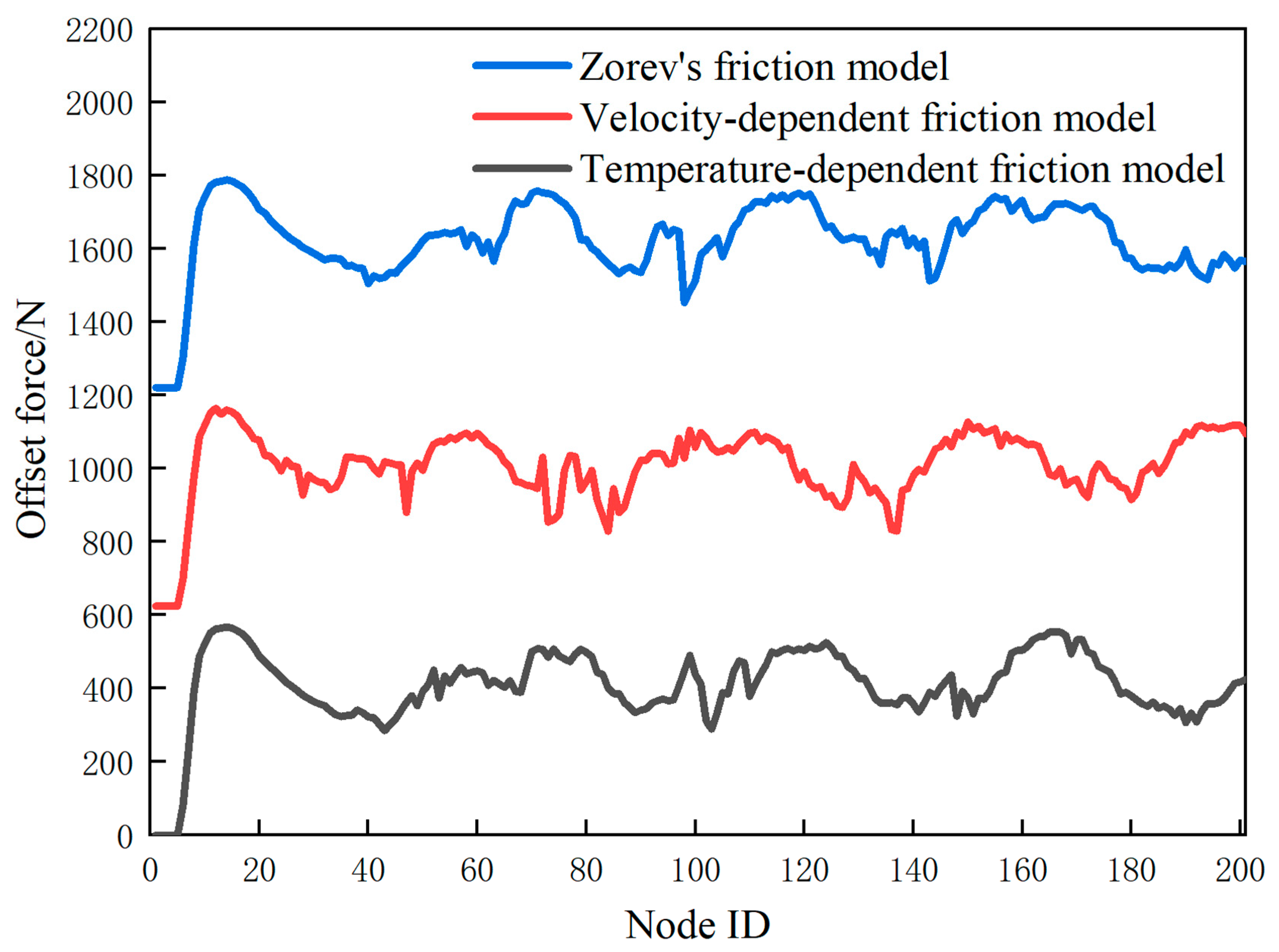
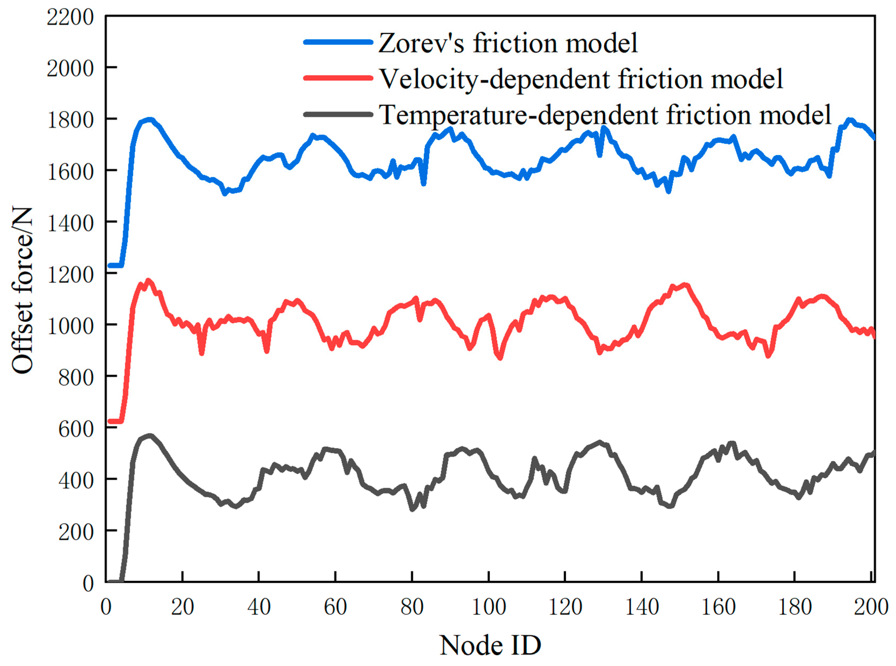
Figure 9 illustrates the distribution of tool surface temperatures calculated using a temperature-dependent friction model. The highest temperature occurs at the contact position between the front rake face and the chip or near the tool nose radius. Since the back rake face contacts the machined surface, there is a temperature rise on the back rake face. This temperature distribution can also be observed in Figure 10 and Figure 11. Figure 11 shows the distribution of tool surface temperatures calculated using a velocity-dependent friction model. Figure 12, Figure 13, Figure 14, Figure 15, Figure 16, Figure 17 and Figure 18 display the predicted cutting force curves obtained using various friction models. The cutting force prediction curves exhibit a trend of periodic oscillations, and different friction models influence the shape of the cutting force prediction curves.

Figure 9.
Temperature on tool face of temperature-dependent friction model with varied machining conditions.
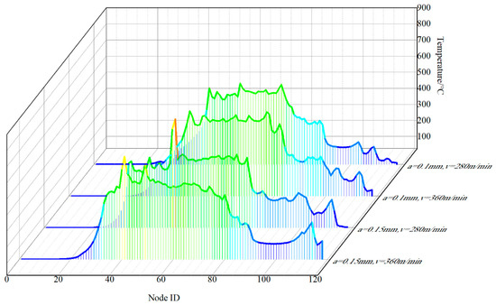
Figure 10.
Temperature on tool face of velocity-dependent friction model with varied machining conditions.
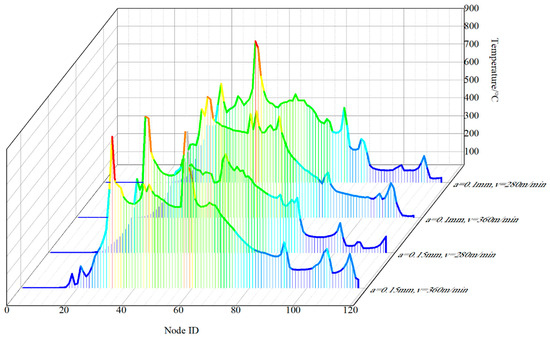
Figure 11.
Temperature on tool face of Zorev’s friction model with varied machining conditions.

Figure 12.
Cutting force when cutting depth is 0.1 mm and cutting speed is 280 m/min.

Figure 13.
Cutting force when cutting depth is 0.1 mm and cutting speed is 360 m/min.
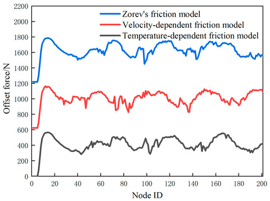
Figure 14.
Cutting force when cutting depth is 0.15 mm and cutting speed is 280 m/min.
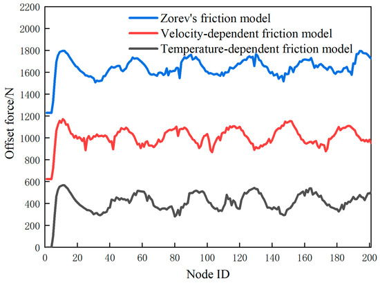
Figure 15.
Cutting force when cutting depth is 0.15 mm and cutting speed is 360 m/min.
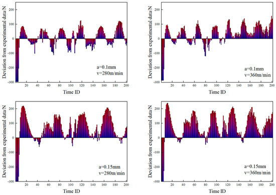
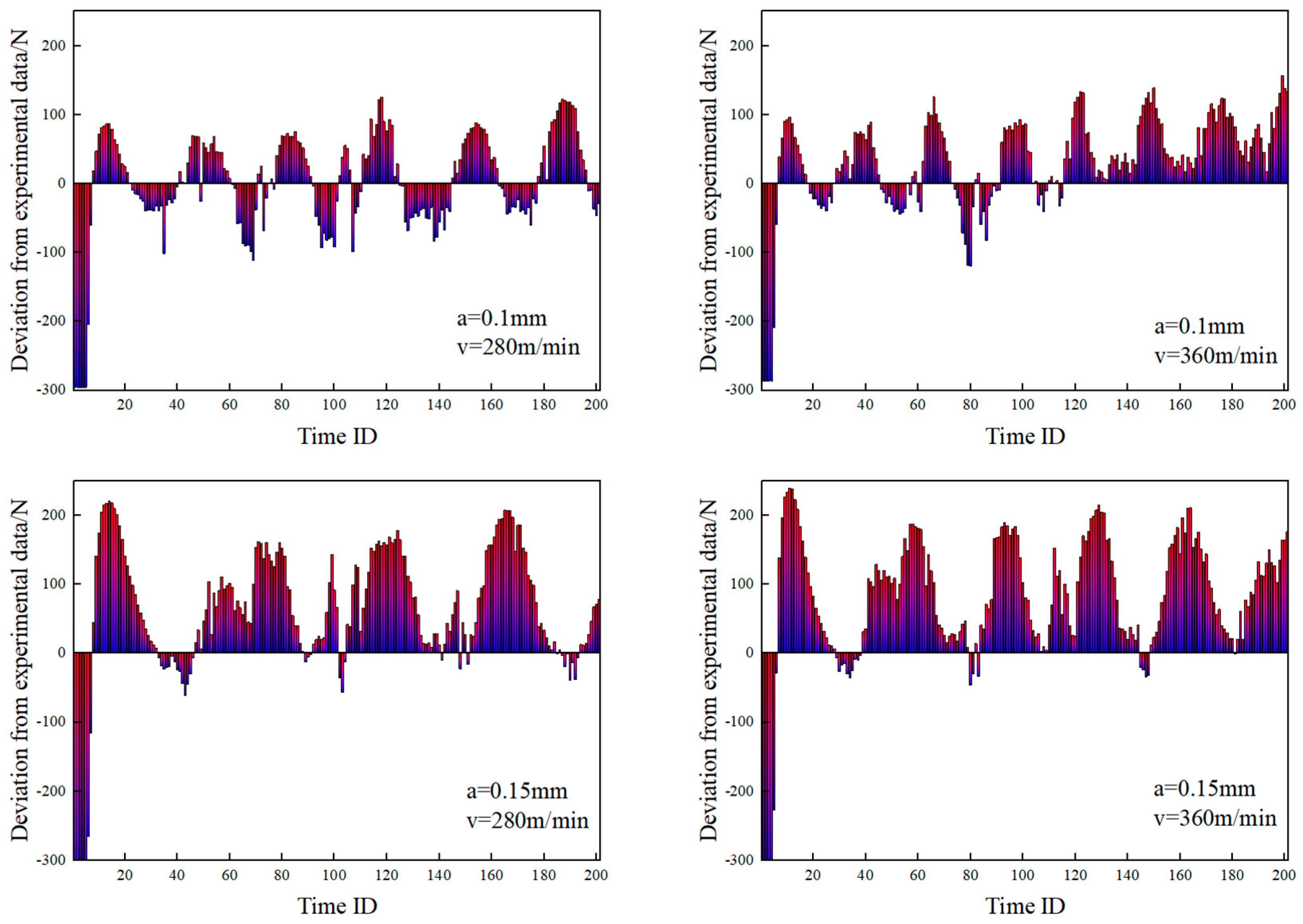
Figure 16.
Deviation of cutting force from experimental data with temperature−dependent friction model.
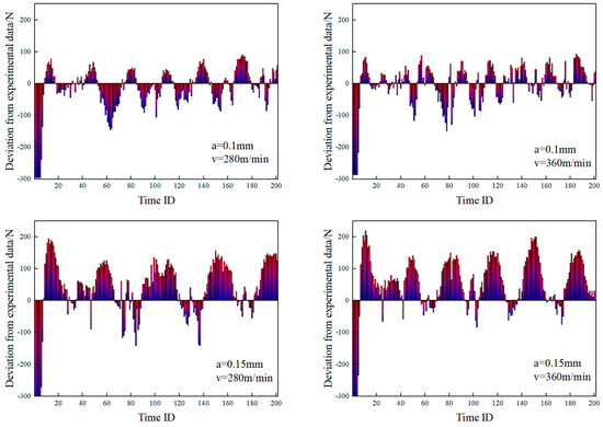
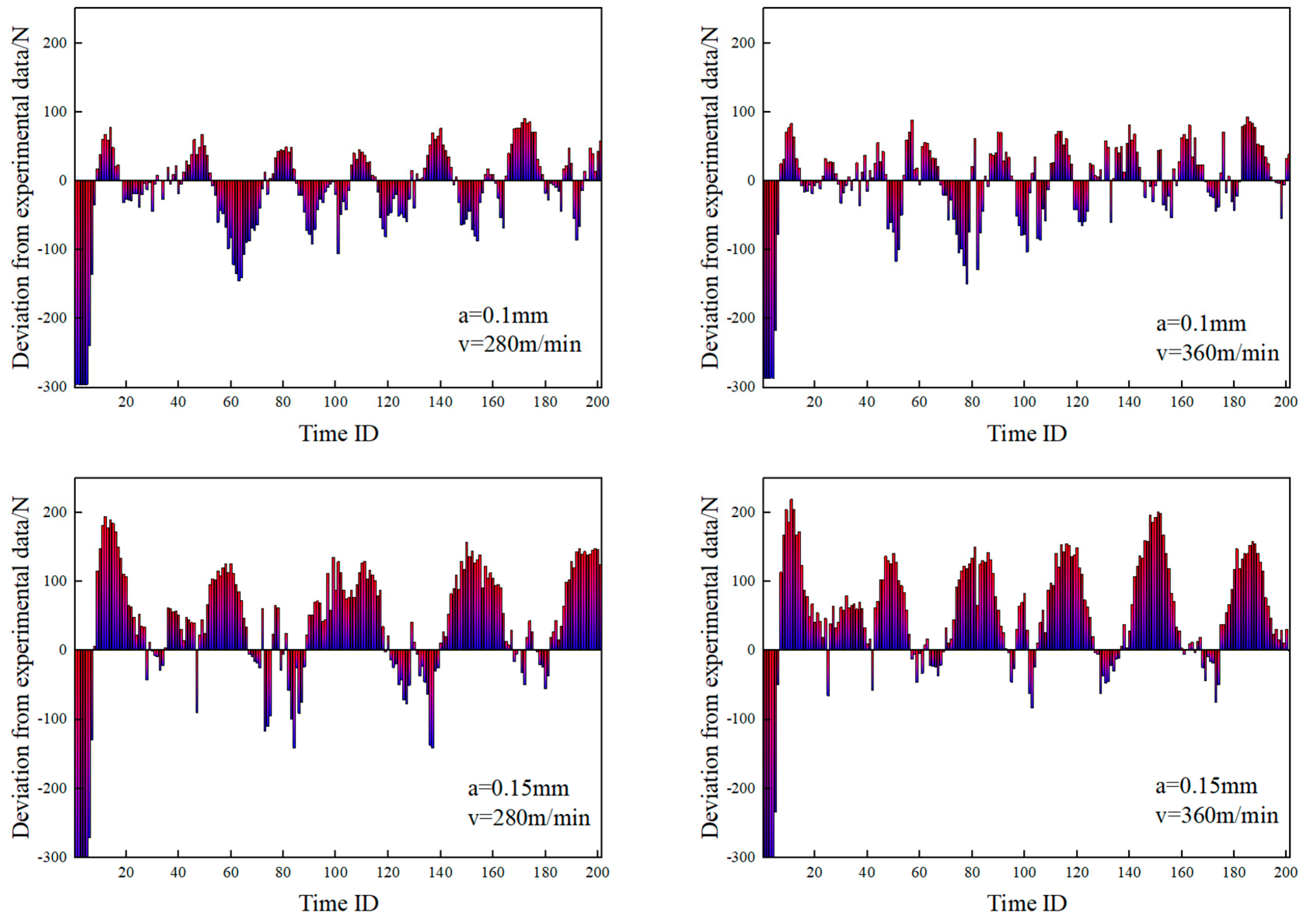
Figure 17.
Deviation of cutting force from experimental data with velocity−dependent friction model.

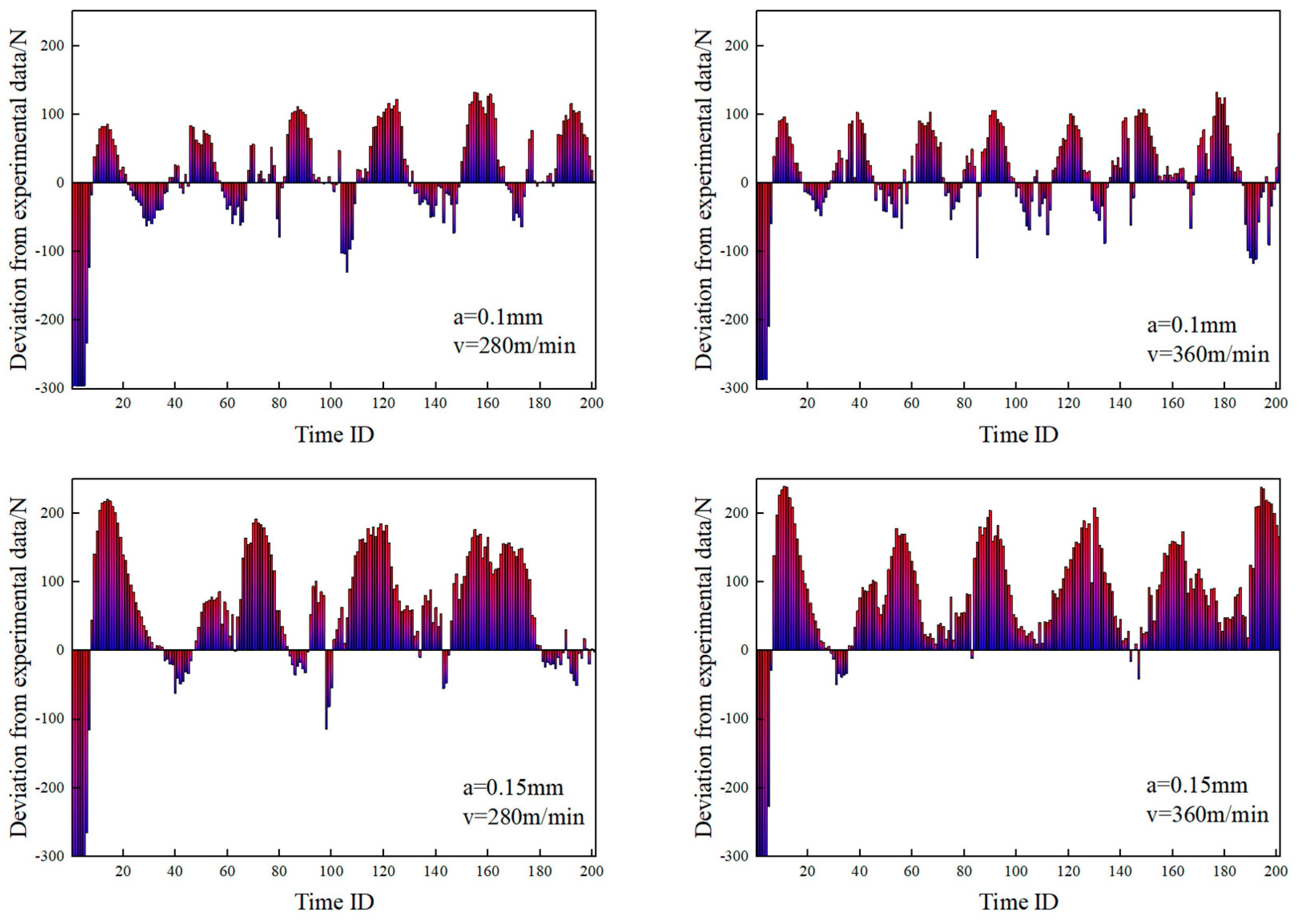
Figure 18.
Deviation of cutting force from experimental data with Zorev’s friction model.
4.2. Discussion
We examined the behavior of the temperature-dependent friction model under varying cutting speeds and depths. As shown in Figure 4, Equation (12) indicates that the friction coefficient decreases linearly with rising temperature. Moreover, the highest shear stress is linked to both the friction coefficient and temperature. Across different cutting conditions, the maximum contact pressure consistently occurs either at the tool’s worn edge or at the point where the tool’s front face meets the chip. The prominence of maximum shear stress on the front face is due to the enhanced Zorev friction model, which is modified by the temperature-dependent friction model. This model offers an expression for peak shear stress, incorporating both adhesive and sliding friction regions on the tool surface. Most of the sliding friction accumulates at the established chip locations. At the interface between the tool’s blunt edge and the workpiece, only minimal sliding friction is observed, whereas the rear face of the tool experiences primarily sliding friction during contact with the material.
The highest sliding velocity is found at the leading cutting edge, gradually decreasing as the chip moves away from it. Consequently, both the contact pressure and shear stress decrease. As the chip moves toward the rounded end of the tool, the sliding velocity continues to decrease. When the sliding velocity approaches zero, the frictional state transitions from sliding to adhesive, resulting in a marked increase in normal contact pressure in that region. Once a certain threshold is surpassed, the frictional stress stabilizes, no longer limited by localized shear flow stresses. This behavior arises from the regulatory mechanism in Equation (12), which prevents localized material from sliding backward. A similar pattern was observed by Zhang et al. [44].
Looking at Figure 5, we can observe a noticeable reduction in stiffness where the chip makes contact with the tool. Plastic deformation in the primary deformation zone is largely governed by the material’s constitutive and damage models. The secondary deformation zone mainly involves the interaction between the tool and the workpiece, while the tertiary zone involves the contact between the tool’s flank face and the machined surface, leading to residual plastic deformation that affects both surface quality and stress. In the secondary deformation zone, where the tool’s edge extends laterally, an adhesive region dominates with zero sliding velocity, experiencing high temperature and stress, which leads to material plasticization. The friction model dictates that the friction coefficient in this region is minimized, corresponding to the lowest maximum frictional shear stress. As the cutting progresses, the plastic strain from this area remains in the chip, causing a thin layer of stiffness degradation at the chip’s base. By applying material constitutive and damage models based on continuum mechanics theory, finite element analysis discretizes the material, accounting for local damage and progressive stiffness degradation until chip separation occurs. Elements that undergo localized damage remain active in the cutting process, staying in contact with the tool geometry. Additionally, when considering the deformation of elements within the secondary deformation zone and their interaction with the tool, the adhesive friction region is defined as an area where most surface nodes exhibit zero relative sliding speed, while some exhibit non-zero speeds due to local plastic deformation. The temperature-dependent friction model effectively captures these dynamics, linking the friction coefficient with maximum frictional shear stress and temperature, making the frictional region inherently non-smooth.
The results from the velocity-dependent friction model are presented in Figure 6 and Figure 7. The original model linked the friction coefficient to cutting speed, but this study extends the model further by incorporating the relationship between the friction coefficient and interfacial sliding velocity. This modification addresses the limitation of the Zorev model, where the friction coefficient remains fixed regardless of cutting conditions. Visually, compared to Zorev’s friction model, the chips formed using the velocity-dependent and temperature-dependent friction models appear softer. However, the velocity-dependent model does not impose a limit on the maximum friction shear stress. Zorev’s model, on the other hand, defines friction types based on the maximum friction shear stress, leading to harder chips. The chips produced using the velocity-dependent friction model exhibit the most sawtooth formations, while the number of saw teeth generated by the other two models is similar.
In the temperature-dependent friction model, the sliding velocity of chips is mainly concentrated at the root of the chips in the second deformation zone and in the sliding friction area formed by the contact between the machined surface and the tool’s back face. Near the tool’s blunt edge, adhesive regions with zero sliding velocity are observed. In contrast, the velocity-dependent friction model shows a higher likelihood of adhesive and non-contact phenomena due to grid deformation, resulting in fewer sliding contact elements and more scattered contact locations. The range of sliding friction areas created by the contact between the machined surface and the tool’s back face is similar to that seen in the temperature-dependent friction model. Additionally, chips generated by the velocity-dependent friction model slide less on the front face, tend to bend more, and are more likely to detach from the tool, resulting in a shorter contact length with the front face.
5. Conclusions
This study employed a refined Johnson–Cook constitutive model, which accounts for dynamic recrystallization processes and softening effects, to simulate the mechanical behavior of materials. Subsequently, two-dimensional thermo-mechanical coupled finite element models were developed to investigate the orthogonal cutting of titanium alloys. These models incorporated different friction models, namely Zorev’s friction model, velocity-dependent friction model, and temperature-dependent friction model. The objective was to explore the performance of these friction models across varying cutting speeds and depths. Here are the key findings:
- Friction models exert direct influence on factors such as the relative sliding velocity at the contact interface, cumulative sliding distance, contact pressure, and frictional shear stress. These factors, in turn, modify the generation of frictional heat and subsequently impact the temperature distribution. Additionally, diverse friction models play a role in shaping the process of chip formation, leading to variations in chip morphology and the frequency of sawtooth patterns. The plastic strain of the chip and its stiffness degradation are primarily influenced by the material constitutive model and damage model. The formation of sawtooth-shaped chips is also greatly affected by these models. Compared to the constitutive model, friction models have a lesser impact on the aforementioned parameters.
- Friction models play a crucial role in shaping the temperature distribution across the tool surface, with specific operating conditions also influencing this distribution. Adjusting the friction coefficient enables the fine-tuning of parameters such as the contact length between the tool and chip, the extent of high-temperature regions on the tool surface, and the overall fluctuation of temperature during the cutting process. Notably, the friction coefficient displays a heightened sensitivity to sliding speed, while the temperature distribution exhibits a greater sensitivity to the choice of friction model compared to variations in operating conditions.
- Irrespective of enhancements to parameters such as the friction coefficient or the maximum friction shear stress, and irrespective of the incorporation of velocity or temperature-dependent factors, these adjustments impact the fluctuation range, periodicity, and local peaks of the cutting force prediction curves. They contribute to improving prediction accuracy within specific operational contexts to a certain extent. However, it is noteworthy that despite these refinements, the general trend of error fluctuations observed across these friction models remains consistent. Moreover, the predictive accuracy of these models tends to diminish with increasing cutting depth.
- This study provides valuable contributions to both industry and academia by improving the understanding of friction’s impact on titanium alloy machining. The research enhances machining efficiency by optimizing cutting conditions through better understanding of friction’s influence on factors like chip formation, cutting forces, and temperature distribution. This can lead to improved tool life, reduced energy consumption, and better material processing. The study’s insights into friction models can improve predictive capabilities for cutting forces, helping manufacturers optimize machining strategies, reduce trial-and-error experiments, and lower operational costs. Additionally, adjusting friction coefficients to minimize wear and heating can lead to significant material cost reductions. The use of an advanced Johnson–Cook model, which accounts for dynamic recrystallization and softening, advances material behavior simulations, contributing to more accurate predictions in machining. The comparison of different friction models (Zorev’s, velocity-dependent, and temperature-dependent) deepens the academic understanding of friction’s role in machining, providing a foundation for future research. Moreover, the study opens avenues for further exploration into complex cutting phenomena, such as tool wear and chip formation, helping to refine material models and simulation techniques for more accurate predictions in real-world manufacturing. Overall, the study provides practical solutions for industry optimization and theoretical advancements for future research in machining processes.
Author Contributions
Methodology, F.Y.; Software, R.Z. (Ruoxi Zhong); Validation, W.Z.; Formal analysis, R.Z. (Run Zhou); Investigation, L.G.; Writing—original draft, Y.W.; Writing—review & editing, Y.W.; Visualization, Y.W.; Supervision, Y.W.; Project administration, Y.W.; Funding acquisition, Y.W. All authors have read and agreed to the published version of the manuscript.
Funding
This research was funded by Jiangsu Key Research and Development Plan (Grant Nos. BE2022129 and BE2022134), and the Fundamental Research Funds for the Central Universities (Grant Nos. 2242022k30031 and 2242022k30033).
Data Availability Statement
The data presented in this study are available on request from the corresponding author. The data are not publicly available due to the reason the data involves core technologies, patents, or trade secrets, and its disclosure could cause losses to the relevant enterprises or institutions.
Acknowledgments
The works described in this paper are substantially supported by a grant from the Key Technologies Research and Development Program (Grant No. 2021YFF0602005), Jiangsu Key Research and Development Plan (Grant Nos. BE2022129 and BE2022134), and the Fundamental Research Funds for the Central Universities (Grant Nos. 2242022k30031 and 2242022k30033), which are gratefully acknowledged.
Conflicts of Interest
The authors declare no conflict of interest.
References
- Ezugwu, E.O.; Bonney, J.; Yamane, Y. An overview of the machinability of aeroengine alloys. J. Mater. Process. Technol. 2003, 134, 233–253. [Google Scholar] [CrossRef]
- Ezugwu, E.O.; Wang, Z.M. Titanium alloys and their machinability—A review. J. Mater. Process. Technol. 1997, 68, 262–274. [Google Scholar] [CrossRef]
- Liang, X.; Liu, Z.; Wang, B. State-of-the-art of surface integrity induced by tool wear effects in machining process of titanium and nickel alloys: A review. Measurement 2019, 132, 150–181. [Google Scholar] [CrossRef]
- Uçak, N.; Çiçek, A.; Outeiro, J.; Aslantas, K.; Çetin, B. Constitutive modelling of Ti-6Al-4V alloy fabricated by laser powder bed fusion and its application to micro cutting simulation. Mech. Mater. 2023, 185, 104756. [Google Scholar] [CrossRef]
- Xi, Y.; Bermingham, M.; Wang, G.; Dargusch, M. SPH/FE modeling of cutting force and chip formation during thermally assisted machining of Ti-6Al-4V alloy. Comput. Mater. Sci. 2014, 84, 188–197. [Google Scholar] [CrossRef]
- Mane, S.; Karagadde, S.; Joshi, S.S.; Kapoor, S.G. Evaluation of an Adhesive Friction Coefficient under Extreme Contact Conditions and Its Application to the Machining Process. Tribol. Trans. 2020, 63, 841–856. [Google Scholar] [CrossRef]
- Dixit, U.; Guduru, R.K.; Rashid, A. Tool wear assessment in dry machining of Ti-6Al-4V using Taguchi approach. Int. J. Interact. Des. Manuf. (IJIDeM) 2024, 1–18. [Google Scholar] [CrossRef]
- Afzal, M.Z.; Khan, S.A.; Raza, S.F.; Naveed, R.; Anwar, S.; Farooq, M.U. Exploring novel PVD coated wiper inserts’ chip breaker designs and feed rates on tool wear and in-depth hole integrity of Ti-6Al-4V alloy when drilling in a dry environment. J. Manuf. Process. 2024, 131, 1667–1685. [Google Scholar] [CrossRef]
- Du, M.; Cheng, Z.; Wang, S. Finite element modeling of friction at the tool-chip-workpiece interface in high speed machining of Ti-6Al-4V. Int. J. Mech. Sci. 2019, 163, 105100. [Google Scholar] [CrossRef]
- Ni, J.; Su, Z.; Tong, K.; Meng, Z.; Li, Z. High performance machining simulation of curved edge broach with surface material constitutive model and tool-chip friction. J. Manuf. Process. 2024, 111, 64–74. [Google Scholar] [CrossRef]
- Liu, S.; Zhang, H.; Zhao, L.; Li, G.; Zhang, C.; Zhang, J.; Sun, T. Coupled thermo-mechanical sticking-sliding friction model along tool-chip interface in diamond cutting of copper. J. Manuf. Process. 2021, 70, 578–592. [Google Scholar] [CrossRef]
- Joo, J.; Kim, J.; Yang, S.M.; Park, H.W.; Kim, D.Y. Tool wear evolution and chip formation of the Ti-6Al-4V end milling under cryogenic cooling and minimum quantity lubrication conditions. Int. J. Adv. Manuf. Technol. 2024, 130, 589–602. [Google Scholar] [CrossRef]
- Mohammed, M.; Pervaiz, S.; Deiab, I. A novel finite element model for thermally induced machining of Ti-6Al-4V. Simul. Model. Pract. Theory 2024, 134, 102928. [Google Scholar]
- Zorev, N. Interrelationship between shear processes occurring along tool face and on shear plane in metal cutting. Proc. Int. Res. Prod. Eng. Conf. 1963, 42–49. [Google Scholar]
- Avevor, Y.; Vincent, J.; Faure, L.; Moufki, A.; Philippon, S. An ALE approach for the chip formation process in high speed machining with transient cutting conditions: Modeling and experimental validation. Int. J. Mech. Sci. 2017, 130, 546–557. [Google Scholar] [CrossRef]
- Xu, X.; Zhang, J.; Outeiro, J.; Xu, B.; Zhao, W. Multiscale simulation of grain refinement induced by dynamic recrystallization of Ti-6Al-4V alloy during high speed machining. J. Mater. Process. Technol. 2020, 286, 116834. [Google Scholar] [CrossRef]
- Wang, Z.; Zhang, J.; Li, G.; Xu, Z.; Zhang, H.; Zhang, J.; Hartmaier, A.; Fang, F.; Yan, Y.; Sun, T. Anisotropy-Related Machining Characteristics in Ultra-Precision Diamond Cutting of Crystalline Copper. Nanomanuf. Metrol. 2020, 3, 123–132. [Google Scholar] [CrossRef]
- Özel, T.; Zeren, E. Determination of work material flow stress and friction for FEA of machining using orthogonal cutting tests. J. Mater. Process. Technol. 2004, 153–154, 1019–1025. [Google Scholar] [CrossRef]
- Usui, E.; Shirakashi, T. Mechanics of Machining from Descriptive to Predictive Theory, on the Art of Cutting Metals 75 Years Later; ASME: New York, NY, USA, 1982. [Google Scholar]
- Afrasiabi, M.; Saelzer, J.; Berger, S.; Iovkov, I.; Klippel, H.; Röthlin, M.; Zabel, A.; Biermann, D.; Wegener, K. A Numerical-Experimental Study on Orthogonal Cutting of AISI 1045 Steel and Ti-6Al-4V Alloy: SPH and FEM Modeling with Newly Identified Friction Coefficients. Metals 2021, 11, 1683. [Google Scholar] [CrossRef]
- Johnson, R.; Cook, W.K. A constitutive model and data for metals subjected to large strains high strain rates and high temperatures. In Proceedings of the 7th International Symposium on Ballistics, The Hague, The Netherlands, 19–21 April 1983. [Google Scholar]
- Tan, J.Q.; Zhan, M.; Liu, S.; Huang, T.; Guo, J.; Yang, H. A modified Johnson–Cook model for tensile flow behaviors of 7050-T7451 aluminum alloy at high strain rates. Mater. Sci. Eng. A 2015, 631, 214–219. [Google Scholar] [CrossRef]
- Kumar, C.S.; Zeman, P.; Polcar, T. A 2D finite element approach for predicting the machining performance of nanolayered TiAlCrN coating on WC-Co cutting tool during dry turning of AISI 1045 steel. Ceram. Int. 2020, 46, 25073–25088. [Google Scholar] [CrossRef]
- Aridhi, A.; Perard, T.; Valiorgue, F.; Courbon, C.; Rech, J.; Brosse, A.; Girinon, M.; Truffart, B.; Karaouni, H. Comparison of the CEL and ALE approaches for the simulation of orthogonal cutting of 15-5PH and 42CrMo4 materials. Proc. Inst. Mech. Eng. Part B J. Eng. Manuf. 2023, 237, 1726–1736. [Google Scholar] [CrossRef]
- Dumanić, I.; Jozić, S.; Bagavac, P.; Bajić, D. Orthogonal cutting simulation of EN AW 6082 T6 alloy using a coupled Eulerian-Lagrangian approach. Heliyon 2023, 9, e14821. [Google Scholar] [CrossRef] [PubMed]
- Wang, B.; Liu, Z. Shear localization sensitivity analysis for Johnson–Cook constitutive parameters on serrated chips in high speed machining of Ti-6Al-4V. Simul. Model. Pract. Theory 2015, 55, 63–76. [Google Scholar] [CrossRef]
- Ducobu, F.; Arrazola, P.J.; Rivière-Lorphèvre, E.; Filippi, E. On the selection of an empirical material constitutive model for the finite element modeling of Ti-6Al-4V orthogonal cutting, including the segmented chip formation. Int. J. Mater. Form. 2021, 14, 361–374. [Google Scholar] [CrossRef]
- Wu, S.; Chen, F.; Wang, C.L. Machining mechanism and stress model in cutting Ti-6Al-4V. Int. J. Adv. Manuf. Technol. 2024, 131, 2625–2639. [Google Scholar] [CrossRef]
- Liu, L.; Wu, W.; Zhao, Y.; Cheng, Y. Subroutine Embedding and Finite Element Simulation of the Improved Constitutive Equation for Ti-6Al-4V during High-Speed Machining. Materials 2023, 16, 3344. [Google Scholar] [CrossRef]
- Zhu, B.; Xiong, L.; Xu, M. Double-edged cutting simulation with a new combined constitutive model for AISI 1045 steel. J. Mater. Process. Technol. 2022, 302, 117496. [Google Scholar] [CrossRef]
- Lei, M.; Sun, G.; Yang, G.; Wen, B. A computational mechanical constitutive modeling method based on thermally-activated microstructural evolution and strengthening mechanisms. Int. J. Plast. 2024, 173, 103881. [Google Scholar] [CrossRef]
- Wagoner Johnson, A.J.; Bull, C.W.; Kumar, K.S.; Briant, C.L. The influence of microstructure and strain rate on the compressive deformation behavior of Ti-6Al-4V. Metall. Mater. Trans. A 2003, 34, 295–306. [Google Scholar] [CrossRef]
- Ullah, I.; Akinlabi, E.T.; Songmene, V.; Kouam, J.; Sadeghifar, M. A multiscale finite element modeling for predicting the surface integrity induced by thermo-mechanical loads during high-speed milling of Ti-6Al-4V. CIRP J. Manuf. Sci. Technol. 2024, 52, 246–263. [Google Scholar] [CrossRef]
- Liu, G.; Zhang, D.; Yao, C. Investigation of the grain refinement mechanism in machining Ti-6Al-4V: Experiments and simulations. J. Manuf. Process. 2023, 94, 479–496. [Google Scholar] [CrossRef]
- Sun, Y.; Li, G.; He, Z.; Kong, X. The advance of research on constitutive model used in finite element simulation of metal cutting. Proc. Inst. Mech. Eng. Part C J. Mech. Eng. Sci. 2022, 236, 4921–4945. [Google Scholar] [CrossRef]
- Johnson, G.R.; Cook, W.H. Fracture characteristics of three metals subjected to various strains, strain rates, temperatures and pressures. Eng. Fract. Mech. 1985, 21, 31–48. [Google Scholar] [CrossRef]
- Hillerborg, A.; Modéer, M.; Petersson, P.E. Analysis of crack formation and crack growth in concrete by means of fracture mechanics and finite elements. Cem. Concr. Res. 1976, 6, 773–781. [Google Scholar] [CrossRef]
- Tao, Z.; Lovell, M.R.; Yang, J.C. Evaluation of interfacial friction in material removal processes: The role of workpiece properties and contact geometry. Wear 2004, 256, 664–670. [Google Scholar] [CrossRef]
- Moufki, A.; Molinari, A.; Dudzinski, D. Modelling of orthogonal cutting with a temperature dependent friction law. J. Mech. Phys. Solids 1998, 46, 2103–2138. [Google Scholar] [CrossRef]
- Usui, E.; Shirakashi, T.; Kitagawa, T. Analytical Prediction of Three Dimensional Cutting Process. 1977. Available online: https://xueshu.baidu.com/usercenter/paper/show?paperid=52d3283ff779c1ebb1f32da1b70b6de2&site=xueshu_se (accessed on 10 January 2025).
- Özel, T.; Altan, T. Determination of workpiece flow stress and friction at the chip–tool contact for high-speed cutting. Int. J. Mach. Tools Manuf. 2000, 40, 133–152. [Google Scholar] [CrossRef]
- Fu, J.; Wang, F.L. Cr12MoVPhysical simulation and experimental research on Cr12MoV cutting machining. Mod. Manuf. Eng. 2014, 93–98. [Google Scholar] [CrossRef]
- He, Z. Experimental Study on Serrated Chip and Cutting Force in High Speed Cutting of Ti-6Al-4V. Master’s Thesis, Tianjin University of Technology and Education, Tianjin, China, 2022. [Google Scholar]
- Zhang, N.; Klippel, H.; Kneubühler, F.; Afrasiabi, M.; Kuffa, M.; Wegener, K. Investigation of friction modeling on numerical Ti6Al4V cutting simulations. Int. J. Mech. Sci. 2024, 274, 109231. [Google Scholar] [CrossRef]
Disclaimer/Publisher’s Note: The statements, opinions and data contained in all publications are solely those of the individual author(s) and contributor(s) and not of MDPI and/or the editor(s). MDPI and/or the editor(s) disclaim responsibility for any injury to people or property resulting from any ideas, methods, instructions or products referred to in the content. |
© 2025 by the authors. Licensee MDPI, Basel, Switzerland. This article is an open access article distributed under the terms and conditions of the Creative Commons Attribution (CC BY) license (https://creativecommons.org/licenses/by/4.0/).