Article

Study on the Effect of Laser Shock Angle on Surface Integrity and Wear Performance of H13 Steel

1
Sichuan Huadian Gongxian Power Generation Co., Ltd., Yibin 644500, China
2
College of Marine Equipment and Mechanical Engineering, Jimei University, Xiamen 361021, China
3
Xiamen XGMA CREC Heavy Machinery Co., Ltd., Xiamen 361023, China
4
School of Marine Mechatronics, Xiamen Ocean Vocational College, Xiamen 361000, China
*
Author to whom correspondence should be addressed.
Lubricants 2025, 13(11), 502; https://doi.org/10.3390/lubricants13110502 (registering DOI)
Submission received: 15 October 2025 / Revised: 12 November 2025 / Accepted: 14 November 2025 / Published: 17 November 2025

Abstract

The internal surfaces of hot-working dies are prone to wear and fatigue fracture during service, often necessitating surface modification and strengthening. Among available techniques, laser shock peening (LSP) is an effective surface strengthening method. However, when treating internal surfaces, achieving perpendicular laser incidence is difficult, and irradiation must often be applied at an angle. To clarify the relationship between the laser incidence angle and the strengthening effect, this study applied laser shock peening to H13 steel at various incidence angles(0°, 15°, 30°, 45°) with a spot diameter of 3 mm, using laser energies of 8 J, 8.2 J, 9.2 J, and 11.3 J, respectively, and maintaining a fixed power density of 1.41 GW/cm2. By maintaining a consistent power density through laser energy compensation, the influence of the incidence angle on surface integrity and wear resistance of the hole structure was systematically investigated. The results show that as the impact angle increases from 0° to 45°, the depth of the affected material layer gradually decreases. Surface microhardness and residual compressive stress peak at a 30° impact angle, reaching values of 633.5 HV1 and 517.4 Mpa, respectively. Wear tests indicated that the friction coefficient was lowest at 30° (0.542), with the dominant wear mechanism shifting from abrasive to adhesive wear. Under controlled power density conditions, oblique laser impact improves surface properties at the expense of a reduced thickness of the affected layer.

1. Introduction

H13 hot-work tool steel is widely used in hot forging dies, die-casting molds, extrusion dies, and automotive component manufacturing due to its excellent thermal fatigue resistance, high toughness, high hardenability, and wear resistance [1]. However, small-hole structures such as cooling channels and ejector pin holes, which are commonly found in mold designs, continuously endure cyclic loading [2], friction wear [3], and thermal shock [4] during service. These structures are highly susceptible to failure, typically manifesting as fatigue cracking around the holes, microstructural degradation, and wear. Such failures significantly limit the overall service life of the mold [5]. Therefore, there is an urgent need to develop effective strengthening techniques specifically targeting these small-hole regions. Wang et al. [6] subjected mold steel to nitriding treatment, systematically characterizing the microstructural evolution, microhardness distribution, and layer thickness variation across different nitrided layers. They analyzed the wear mechanism influenced by varying phase compositions. Fu et al. [7] applied two distinct dual-phase treatment methods for surface coating on components, enhancing the coating’s mechanical properties, corrosion resistance, and wear resistance. Zheng et al. [8] performed ultrasonic rolling on component surfaces to improve surface roughness and hardness while introducing residual compressive stresses to enhance wear resistance. Although conventional surface strengthening methods such as nitriding, coating, and ultrasonic rolling have been extensively studied and applied to mold surface treatment, their effectiveness remains limited for meeting demanding operational requirements due to the complex internal structures of deep/small holes and the restricted access of tools into these cavities.
Laser shock peening (LSP) is an advanced surface modification technology capable of efficiently inducing residual compressive stresses and significantly enhancing the fatigue and wear resistance of metallic materials, thereby offering a promising approach for mold strengthening [9]. Owing to its high energy density and ability to produce deep plastic deformation without thermal damage, LSP has attracted increasing attention in the strengthening of tool steels and other high-performance alloys. Previous studies have demonstrated that LSP can substantially improve the mechanical and tribological properties of H13 steel. Lu et al. [10] reported that LSP effectively enhanced surface hardness and extended the service life of H13 steel molds. Yin et al. [11] found that LSP markedly increased the microhardness and elastic modulus of treated components, resulting in improved wear resistance. Feng et al. [12] attributed these enhancements to grain refinement and the introduction of residual compressive stresses, which collectively increased impact toughness and surface integrity. Moreover, Lu et al. [13] showed that multiple LSP impacts further reduced the wear rate of H13 steel, achieving a notable improvement in wear performance. However, most existing research and practical applications of LSP have primarily focused on normal (vertical) laser impacts applied to flat or external surfaces. For complex geometries such as small holes and inner cavities in molds, vertical laser incidence is often impractical, making oblique laser impacts a necessary alternative. Tang et al. [14] demonstrated that oblique LSP can effectively improve surface roughness, introduce residual compressive stresses, and refine grains, thereby enhancing fatigue life. Lin et al. [15] further established an evaluation framework for oblique LSP, optimizing process parameters such as laser energy, spot diameter, and impact frequency to maximize strengthening efficiency. Despite these advances, the fundamental mechanisms governing stress wave propagation, plastic deformation behavior, and the resultant strengthening effects under oblique LSP—particularly for small hole walls—remain inadequately understood. A systematic investigation into the effects of laser incidence angle on the surface integrity and mechanical properties of H13 steel is therefore essential to deepen the understanding of oblique LSP mechanisms and to expand its applicability in complex mold structures. Although a large number of studies have been dedicated to LSP and its improvement of material properties, most of them have focused on the case of flat or outer surfaces under vertical laser incidence. Although a few studies have explored oblique laser shock and established a preliminary evaluation framework, the key issue of how the laser incident Angle affects the surface integrity and tribological properties of the internal keyhole structure still lacks systematic research.
In this study, the power density distribution was precisely regulated by controlling the elliptical laser spot profile, thereby achieving consistent power density across different incidence angles. The research aims to elucidate the strengthening mechanism of materials subjected to oblique laser impacts and to systematically investigate the influence of the incidence angle on the residual stress distribution and microstructural evolution within the pore structures. Accordingly, the effects of oblique laser impact on the microstructure and mechanical properties of H13 steel under constant power density were comprehensively examined, with particular emphasis on revealing the underlying mechanisms by which the laser incidence angle governs surface integrity and strengthening behavior.

2. Materials and Methods

2.1. Materials and LSP Experiment

Laser power density is one of the key factors influencing laser-induced surface modification. Its value is determined by the combination of laser energy, spot diameter, and pulse width. Laser power density satisfies the following Equation (1):
I 0   =   E π r 2 τ
where “E” is the laser energy (J), “r” is the spot radius (mm), and “τ” is the laser pulse width (ns).
During the laser oblique impact process, the laser beam strikes the surface of the metal target at a certain angle, causing the shape of the spot projected onto the metal target surface to change from circular to elliptical [16]. As shown in Figure 1, let “r” denote the radius of the laser spot when circular. When the laser beam is incident at an angle, the circular spot becomes elliptical. At this point, the angle of incidence is denoted as “θ”, and the radius of the ellipse’s minor axis is denoted as “a”. Then, a = r, and the radius of the ellipse’s major axis b = a/cosθ. Derive Equation (2):
I 0   =   Ecos θ π r 2 τ
To ensure that the laser power density received by the material surface remains equivalent to vertical impact when incident at oblique angles, an energy compensation method is employed. This maintains constant power density during oblique laser incidence, with the energy relationship satisfying Equation (3).
E 0   =   E cos θ
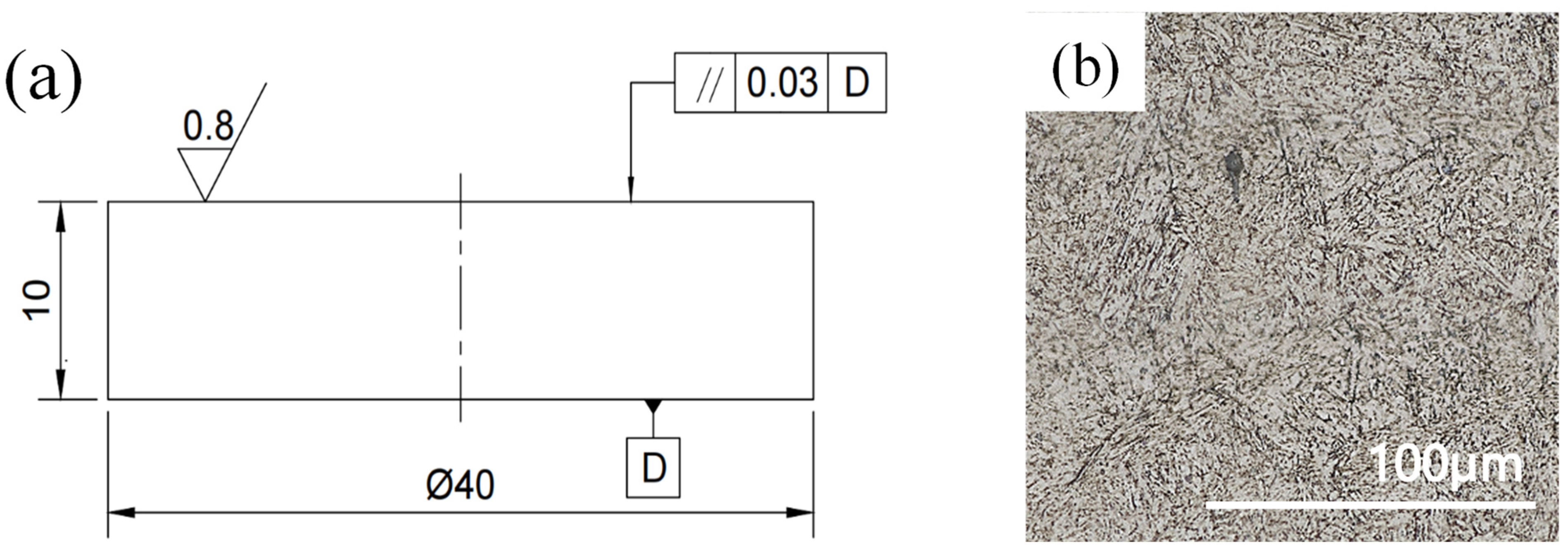
As previously mentioned, the laser oblique impact test is conducted on a disc-equivalent specimen. By controlling the angle between the incident laser beam and the plane, it simulates the irradiation effect when the laser enters through an internal hole. Its advantages include not only enabling comparison with laser beams incident perpendicular to the surface but also facilitating surface integrity and wear performance testing. The specimen is made of H13 steel with dimensions of Φ40 mm × 10 mm, as shown in Figure 2. Its chemical composition is detailed in Table 1: Chemical Composition of H13 Steel Specimen. A high-purity, uniformly dense microstructure was achieved through vacuum induction melting and vacuum arc remelting processes. The H13 steel heat treatment process was as follows: heated at a rate of 0.5 °C/min to 850 °C and held for 2.5 h; further heated to 1050 °C and held for 2.5 h before quenching; tempered twice at 500 °C for 3.5 h each time; and finally air-cooled. The hardness of the sample was measured to reach 522HV1 after heat treatment. The specimens were mechanically polished using a series of SiC abrasive papers with grit sizes ranging from #180 to #2000. Subsequently, diamond spray polishing compound was applied to achieve a mirror finish, controlling the surface roughness to Ra ≤ 0.2 μm. Finally, the circular specimens underwent ultrasonic cleaning in ethanol for 5 min.
LSP was conducted using a (TYRIDA LAMBER-12, Xi’an, China) laser system operating at a wavelength of 1064 nm with a pulse duration of 20 ns. A black tape coating was applied to the specimen surface as an absorbing layer, while a 1 mm-thick water layer was used as the confinement medium to facilitate the propagation of high-pressure shock waves into the material. The laser spot diameter was fixed at 3 mm. Owing to its high absorption efficiency and stable surface characteristics, the black coating exhibited negligible sensitivity to variations in the laser incidence angle, thereby ensuring stable plasma formation and consistent shock wave pressure generation [17]. LSP experiments were performed at incident angles of 0°, 15°, 30°, and 45°. To maintain a constant laser power density of 1.41 GW/cm2, the corresponding laser energies were calculated using Equation (2) as 8 J, 8.2 J, 9.2 J, and 11.3 J, respectively. The detailed experimental parameters are summarized in Table 2.

2.2. Detection and Characterization

The surface morphology of the disc specimens was examined using a laser confocal microscope (VK-X1000K, Keyence, Osaka, Japan). Each specimen was scanned over a 4 mm × 4 mm area, and the resulting surface topography data were analyzed with Vision Editor software (1.6.002) to determine the surface roughness parameter (Ra). Three measurements were performed for each sample, and the average value was reported.
The specimens were subsequently sectioned into blocks via wire cutting, followed by grinding, polishing, and ultrasonic cleaning. They were then etched with a 4% nitric acid–alcohol solution, rinsed, and analyzed for metallographic features using the VK-X1000K laser confocal microscope at magnifications of 50× and 150×. Microhardness testing was carried out with a Falcon 500 Vickers microhardness tester under a load of 1 kg and a dwell time of 10 s. Indentations were made at the surface and along the cross-sectional depth, with each reported value representing the average of three measurements. Residual stress analysis was performed using an HDS-I X-ray stress analyzer, with chromium (Cr) as the target material. Measurements were conducted using the sin2Ψ method, where Ψ varied from 0° to 45° in increments of 0.1°. Multiple measurements were taken to reduce experimental error; anomalous readings were excluded, and the mean value of three valid measurements was reported as the surface residual stress.
Friction and wear behavior were evaluated using a multifunctional tribometer (UMT-2, Bruker, CETR, Billerica, MA, USA), as illustrated in Figure 3. During testing, a fixed load ensured point contact between the ZrO2 spherical counterpart (diameter: 9.525 mm, hardness: 72 HRC) and the rotating H13 steel disc specimen. The setup enabled controlled sliding under either lubricated or dry conditions. Wear performance was assessed by measuring the diameter, depth, or volume loss on the ZrO2 ball, and by analyzing the wear track morphology on the disc surface. The test parameters were as follows: normal load of 20 N, rotation speed of 250 rpm, rotation radius of 6 mm, and total duration of 10 h. Each test was repeated three times, and the mean value was reported. The annular wear tracks on the worn discs were characterized using a (ZEISS LSM900, Oberkochen, Germany) laser scanning microscope, and the depth of the most severely worn regions was extracted for analysis.

3. Results

3.1. Surface Topography

Figure 4 presents the surface topography of H13 steel specimens subjected to LSP at different impact angles. The specimen surfaces exhibit numerous protrusions formed by microplastic deformation induced by laser shock peening [18], which contributes to the increase in surface roughness. As the impact angle increases to 15°, the average height difference rises markedly. The three-dimensional topography reveals intensified peak-like structures, and the surface roughness increases from 0.383 μm to 0.470 μm. At this stage, the shock wave acquires a tangential component that induces shear deformation within the surface layer. This non-uniform plastic flow promotes the formation of protrusions and depressions, thereby enhancing surface roughness. The observed roughness variation can be attributed to the gradient increase in the shock pressure field along the direction of laser incidence under oblique impact. As a result, the material deformation becomes asymmetric relative to the shock center, generating undulating folds and pronounced ridge-like features on the surface, which significantly elevate the average height difference [19]. When the impact angle further increases to 30° and 45°, the surface roughness decreases to 0.396 μm and 0.386 μm, respectively. The average height difference diminishes, and the number of sharp surface features reduces, although localized undulations remain visible. Overall, the surface roughness exhibits a gradual decreasing trend. In this range, the normal component of the shock wave weakens and becomes insufficient to induce deep plastic deformation. Meanwhile, the tangential component, though still prominent, primarily causes surface sliding or shallow deformation, resulting in limited overall modification of the surface topography.

3.2. Metallographic Structure, Microhardness and Residual Stress

As illustrated in Figure 5, the microstructure of the material underwent significant refinement after LSP. The surface region exhibited a denser structure, characterized by the transformation of coarse lath martensite into fine lath martensite. This microstructural evolution is typically associated with grain refinement and an increase in dislocation density, which together contribute to enhanced tensile ductility [20]. When the specimens were treated at different impact angles (0–45°), the corresponding thicknesses of the plastic deformation layer were measured to be 136.5 μm, 115.1 μm, 86.4 μm, and 70.8 μm, respectively. With increasing impact angle, the thickness of the plastic deformation layer gradually decreased, corresponding to reductions of approximately 15.7%, 36.7%, and 48.1% compared with that at 0°. This trend arises because the thickness of the plastic deformation layer is governed primarily by the normal component of the laser-induced shock pressure. As the impact angle increases, the effective normal component diminishes, thereby reducing the plastic deformation depth.
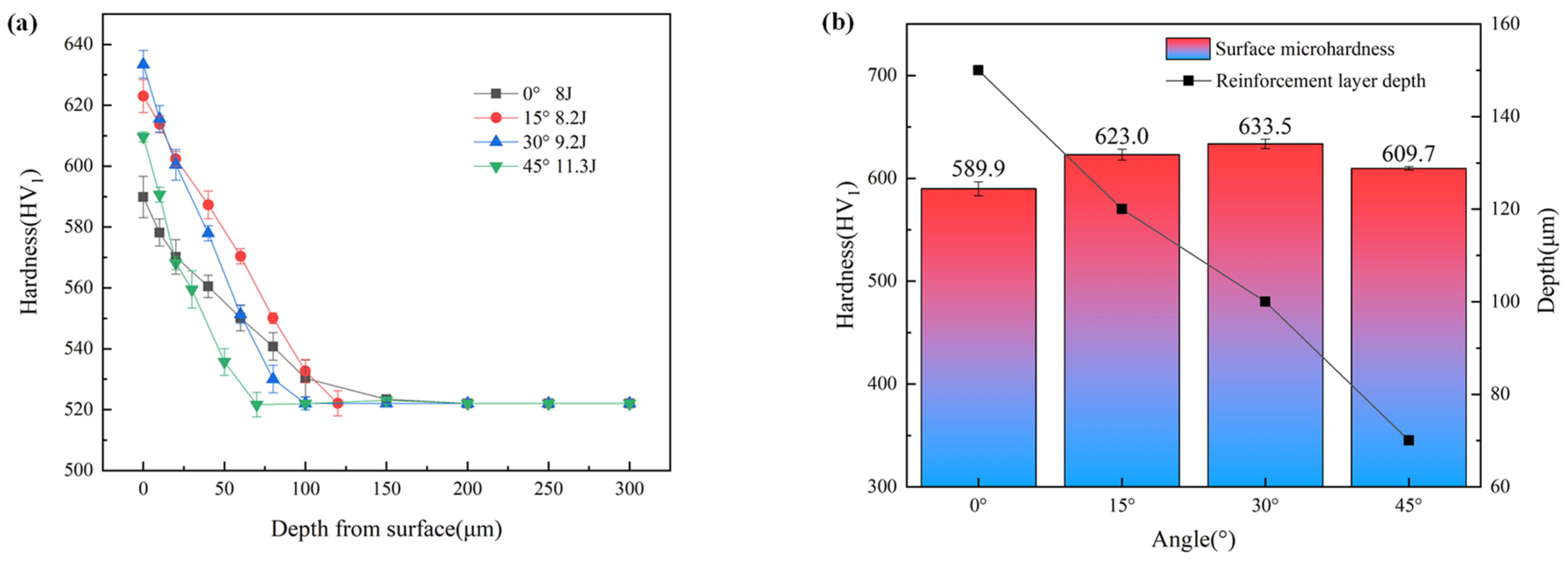
LSP induces high strain-rate plastic deformation on the surface, leading to a significant increase in the surface hardness of H13 steel [21]. The microhardness test results are presented in Figure 6. After LSP at impact angles of 0°, 15°, 30°, and 45°, the depths of the hardened layers were approximately 150 μm, 120 μm, 100 μm, and 70 μm, respectively, showing a gradual decrease with increasing impact angle. This trend is consistent with the observations from metallographic analysis. The corresponding surface microhardness values were 589.9 HV1, 623.0 HV1, 633.5 HV1, and 609.7 HV1, demonstrating an initial increase followed by a slight decrease, with the peak hardness occurring at an impact angle of 30°. The variation in surface hardness with impact angle can be attributed to the combined effects of the normal and tangential components of the shock wave during oblique LSP. At moderate angles (around 30°), these components act synergistically to enhance dislocation density and induce optimal surface strengthening. However, as the incidence angle increases beyond 45°, the overall laser energy absorbed by the surface decreases due to enhanced reflection and dispersion, resulting in a diminished strengthening effect.
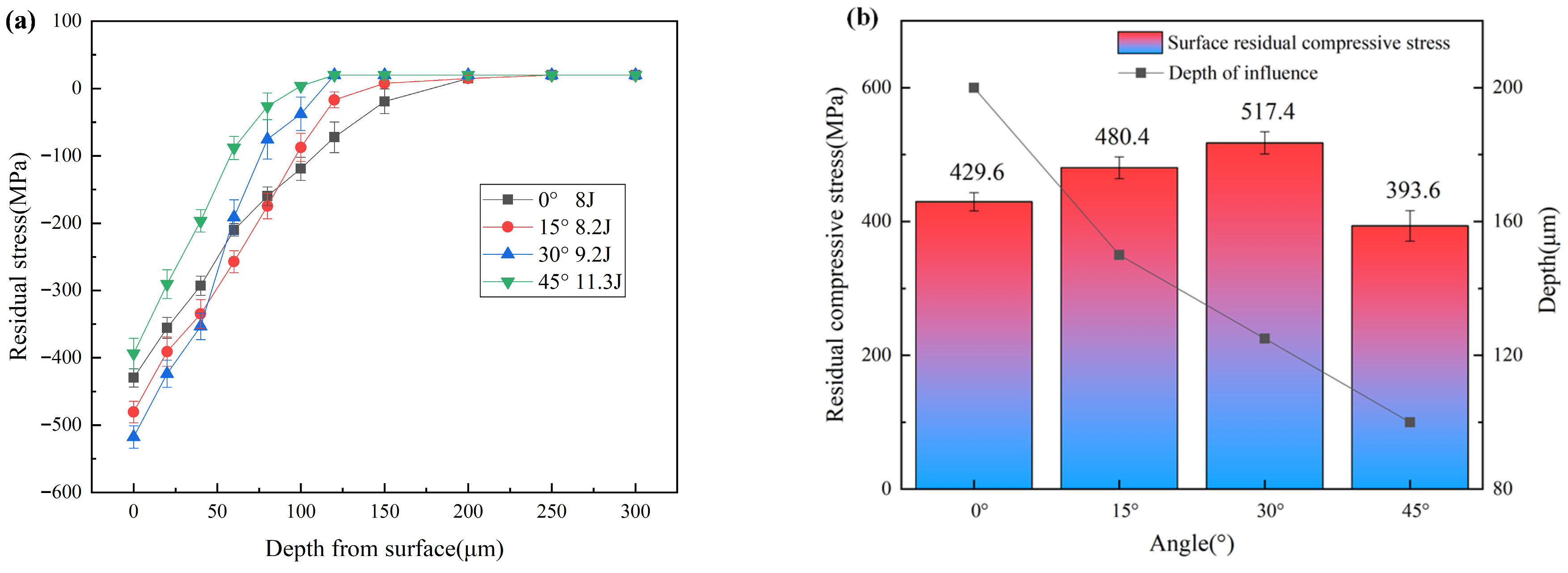
Figure 7 presents the residual stress distributions obtained at different impact angles. Laser shock peening with incidence angles of 0°, 15°, 30°, and 45° generated maximum surface compressive residual stresses of 429.6 MPa, 480.4 MPa, 517.4 MPa, and 393.6 MPa, respectively. As the depth increases, the extent of plastic deformation gradually decreases, and the compressive residual stress approaches zero at depths of approximately 200 μm, 150 μm, 125 μm, and 100 μm, respectively. Under normal (0°) impact, the shock wave pressure is directed perpendicularly to the material surface, allowing efficient energy transmission into the subsurface and inducing deep plastic deformation [22]. In contrast, during oblique impacts, the normal component of the shock wave diminishes with increasing angle, resulting in a reduced ability to penetrate the material and consequently a shallower affected layer. The variation in surface residual compressive stress with impact angle exhibits a trend of initial increase followed by a decrease, reaching a maximum at 30°. This behavior can be attributed to the shear component introduced by oblique impacts, which promotes shear slip and enhances compressive stress within the surface layer. However, at larger angles, stress wave scattering and excessive shear deformation reduce the effective loading efficiency and may compromise surface integrity, leading to a decline in the resultant compressive residual stress.

3.3. Friction and Wear Performances

3.3.1. COF, Wear Profile, and Wear Volume

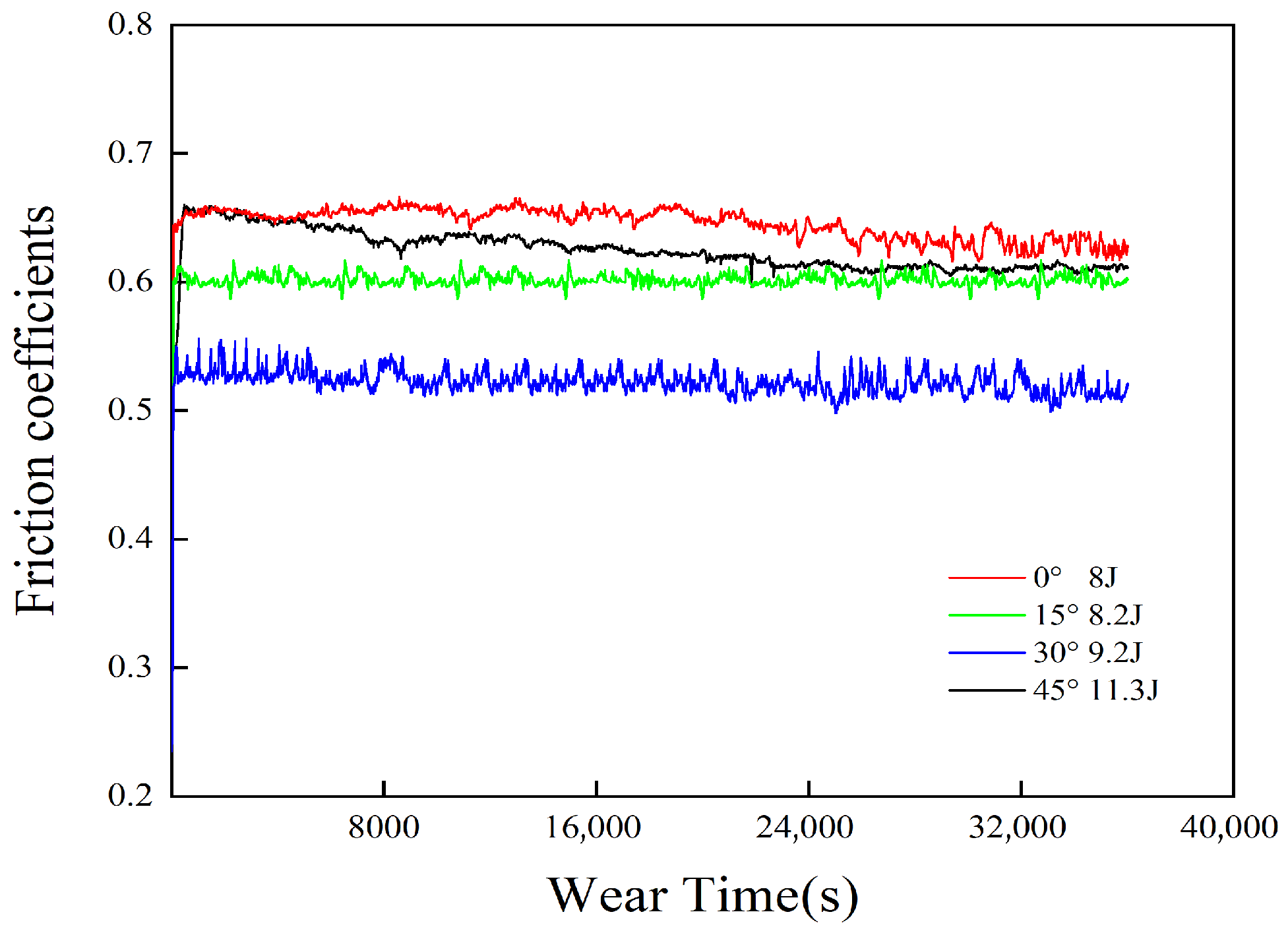
Figure 8 presents the variation in the coefficient of friction (COF) during a 10 h wear test for specimens subjected to different laser impact angles. At the beginning of the test, all specimens exhibited relatively high COF values, which increased rapidly before reaching a steady state after approximately 500 s. Once stabilized, the average COF values for impact angles of 0°, 15°, 30°, and 45° were 0.652, 0.631, 0.603, and 0.542, respectively. The specimen treated at a perpendicular impact angle (0°) showed the highest COF, whereas the COF progressively decreased with increasing impact angle. This trend indicates that the laser impact angle exerts a significant influence on the frictional behavior of the material. The observed variation in COF provides an important criterion for assessing the wear resistance of the laser shock-treated surfaces [23].
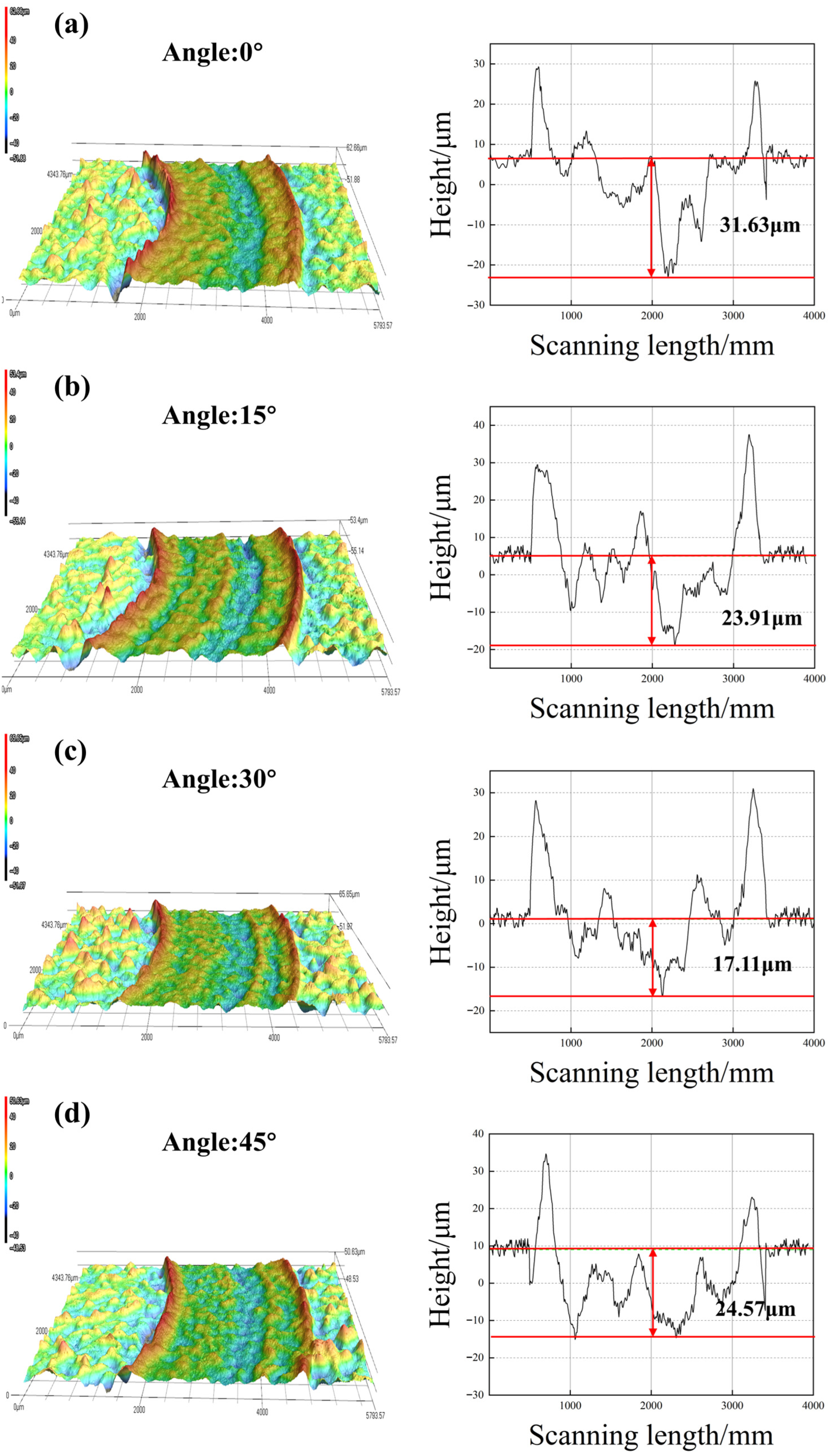
Figure 9 presents the average wear depth obtained from three repeated tests conducted at different impact angles. Overall, the average wear depth exhibits a trend of first decreasing and then increasing as the impact angle increases. To further illustrate this phenomenon, Figure 10 displays a representative set of test results, including the three-dimensional wear profiles and corresponding line-scan data. Figure 10a–d show the three-dimensional morphologies of the worn surfaces under various impact angles. It can be observed that all specimens exhibit surface undulations of different degrees, indicative of typical adhesive wear characteristics. From the wear depth curves, the maximum wear depth under normal (0°) impact is 31.63 μm. As the impact angle increases, the maximum wear depth initially decreases and then increases, reaching 23.91 μm, 17.11 μm, and 24.57 μm at 15°, 30°, and 45°, respectively. These results demonstrate that a moderately inclined impact angle can effectively enhance the wear resistance of the material.
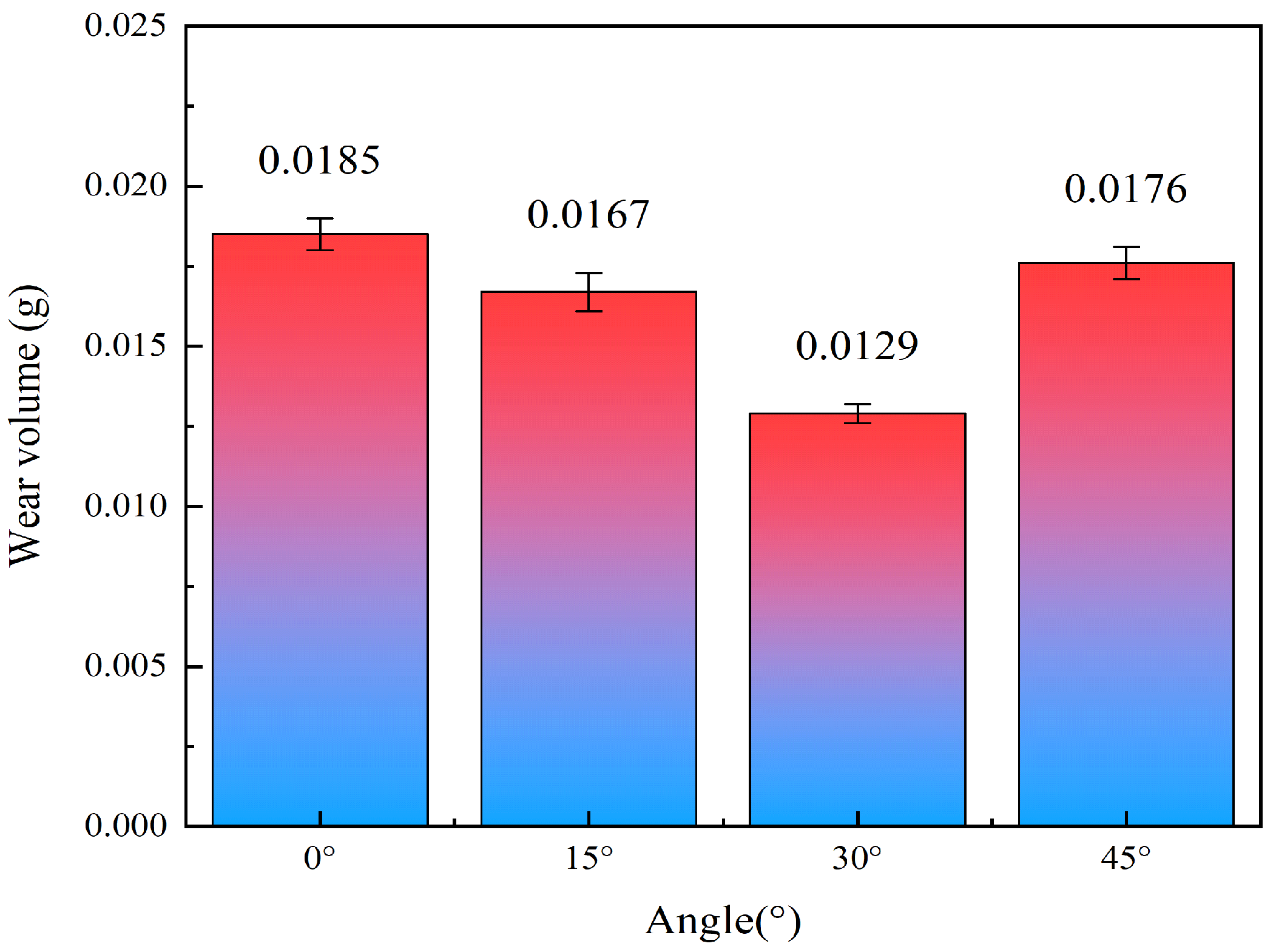
Figure 11 presents the wear rates of specimens treated at different laser impact angles, with measured values of 0.0185 g, 0.0167 g, 0.0129 g, and 0.0176 g corresponding to impact angles of 0°, 15°, 30°, and 45°, respectively. The wear rate exhibits a trend of initially decreasing and then increasing with increasing impact angle, which aligns with the variation observed in maximum wear depth. This correlation indicates that the laser impact angle plays a crucial role in modulating the wear resistance of H13 steel. Overall, the combined results demonstrate that oblique laser impacts enhance the material’s resistance to plastic deformation and wear more effectively than normal impacts.

3.3.2. Wear Morphology

To investigate the evolution of surface morphology in H13 steel during wear, specimens subjected to a 10 h wear test were analyzed using scanning electron microscopy (SEM) and energy-dispersive spectroscopy (EDS), as shown in Figure 12a–d. At an impact angle of 0°, numerous adherent particles and distinct spalling traces were observed on the worn surface. High-magnification images revealed pronounced plow marks near the spalling regions, forming continuous grooves attributed to “cold welding” adhesion between surface asperities during sliding. Subsequent shear forces fractured these junctions, generating abrasive debris. This morphology is characteristic of plastic deformation induced by abrasive wear, indicating that the dominant wear mechanisms are adhesive and abrasive wear [24]. EDS analysis at the characteristic point in Figure 12a1 revealed a significantly elevated Zr content compared with the base matrix, confirming the transfer and adhesion of material from the counterface grinding balls during sliding. In contrast, the specimen impacted at 15° exhibited fewer spalling pits and adherent particles. Under high magnification, only minor grooves and abrasive debris were detected around the spalling regions. EDS results from Figure 12b1 also identified Zr, but at a lower concentration than in the 0° specimen, suggesting that adhesive wear remained dominant but was mitigated, accompanied by slight abrasive wear. At an impact angle of 30°, the number of grooves and adherent particles further decreased, and the surface appeared relatively smooth under magnification. The wear mechanism was primarily adhesive wear, indicating optimal surface integrity. However, at 45°, the worn surface became noticeably rougher, featuring more pronounced grooves and adherent debris. High-magnification images revealed distinct abrasive particles, and elemental mapping of Zone 2 showed increased oxygen content, indicating the onset of oxidative wear. Integrating the findings from the COF evolution (Figure 8), wear profile and volume (Figure 10 and Figure 11), and surface hardness and morphology (Figure 6 and Figure 12), it can be concluded that oblique laser shock impacts promote more pronounced grain refinement and higher dislocation density compared with normal impacts. These effects enhance surface hardness and improve wear resistance. Among the tested angles, the specimen treated at a 30° impact angle exhibited the best wear resistance, followed by 15° and 45°, while the 0° specimen showed the poorest performance.

4. Discussion

During oblique laser impact, the incident force can be resolved into normal and tangential components, as illustrated in Figure 13. The normal component predominantly determines the depth of the hardened layer, whereas the tangential component not only attenuates the normal effect—thereby reducing the hardened layer depth—but also enhances lateral plastic deformation, leading to more pronounced surface distortion. Within the impact angle range of 0–45°, the surface roughness exhibits a non-monotonic trend. At lower angles, the increasing tangential component of the shock pressure markedly intensifies asymmetric plastic flow and microscopic plowing on the surface, thereby amplifying surface undulations and elevating roughness [25]. However, as the angle continues to increase, the normal component diminishes significantly. Despite the relatively large tangential component at higher angles, the reduced normal stress limits the overall plastic deformation, weakening its influence on surface morphology and resulting in a subsequent decline in roughness.
In laser shock peening, the depth of the plastic deformation layer is primarily governed by the normal component of the shock wave and decreases monotonically with increasing impact angle (θ). This occurs because a larger angle weakens the penetration capability of the shock wave within the substrate, thus reducing the extent of induced plastic deformation. Meanwhile, the tangential component acts mainly on the near-surface region, contributing little to the depth of deformation. Nevertheless, oblique impacts introduce substantial tangential stresses that strongly promote shear plastic deformation in the surface layer. This deformation mode facilitates dislocation multiplication and interaction, enabling more significant grain refinement than that produced by normal impacts. This mechanism aligns with previously observed behaviors in laser shock processing, where shear deformation through twinning and dislocation slip serves as a critical pathway for grain subdivision [20,26]. These findings indicate that controlling the tangential component through impact angle adjustment can be an effective approach for tailoring microstructural evolution. Within an optimal angular range, intense shear deformation induced by oblique laser shock can fragment the original grains, forming refined subgrains or even nanocrystalline structures, while simultaneously triggering additional work-hardening effects [27]. In this regime, the beneficial role of the tangential component in promoting dislocation proliferation outweighs the detrimental influence of the reduced normal component. Consequently, the surface layer exhibits elevated dislocation density, finer grain structure, and increased surface hardness and residual compressive stress, which may reach their peak values at specific oblique angles.
To quantitatively describe this phenomenon, the surface residual stress model proposed by Montross et al. [28] was further introduced, as shown in Equation (4). By incorporating the pressure change P = Pmax/cosθ caused by the oblique impact into the model, as shown in Equation (5), the reason why the surface residual stress is enhanced within a certain Angle range is theoretically explained. This indicates that introducing the impact Angle as a key variable into the model is crucial for accurately predicting the strengthening effect of oblique laser impact.
σ surf = P max 2 1 + λ 2 μ 1 4 2 π r l 1 + ν L p
In the equation, σsurf represents the residual stress on the material surface, while λ and μ are the Lamé constants calculated from E and υ: λ = ν E / 1 + ν 1 2 ν , μ = E / 2 1 + ν , where E is the elastic modulus, υ is Poisson’s ratio, rl is the laser spot radius, and Lp is the effective depth of residual compressive stress. Substituting the pressure variation P = P m a x / c o s θ generated by the oblique laser impact into Equation (4) yields Equation (5).
σ surf   = P 2 cos θ 1 + λ 2 μ 1 4 2 π r l 1 + ν L p
However, as the impact angle continues to increase, the rapid attenuation of the normal component becomes the dominant factor, resulting in a reduced capacity for plastic deformation and, consequently, lower energy coupling efficiency. When the normal component is insufficient to effectively drive plastic deformation, the strengthening contribution of the tangential component becomes outweighed by the diminishing influence of the normal component. As a result, the overall degree of plastic deformation decreases, leading to reductions in both surface hardness and residual compressive stress from their peak values. This behavior suggests the existence of an optimal range of impact angles, within which the synergistic interaction between the tangential and normal components is maximized. Although the hardened layer depth is somewhat reduced in this range, the combined effects of both components yield superior surface mechanical properties compared to those produced under normal impact conditions.

5. Conclusions

This study presents a comprehensive investigation into the surface integrity and wear performance of H13 tool steel subjected to oblique laser shock treatment. Based on the experimental results and discussion, the following conclusions are drawn:
(1)
By compensating for the laser energy to maintain a constant power density, the influence of the laser incidence angle on the surface integrity of H13 steel was systematically examined. As the incidence angle increased from 0° to 45°, the surface characteristics exhibited distinct and consistent variations. The surface roughness first increased and then decreased, reaching its maximum value at an angle of 15°. In contrast, the thickness of the plastic deformation layer decreased progressively with increasing angle, with the maximum reduction reaching 48.1%. Notably, both surface microhardness and residual compressive stress followed a non-monotonic trend—initially increasing and subsequently decreasing—and simultaneously attained their peak values at an incidence angle of 30°, corresponding to 633.5 HV1 and 517.4 MPa, respectively.
(2)
The laser impact angle plays a crucial role in governing the friction and wear behavior of H13 steel. With increasing impact angle, the friction coefficient, wear depth, and wear rate exhibit a non-monotonic variation—initially decreasing and subsequently increasing—achieving optimal performance at approximately 30°. Theoretical analysis indicates that a moderately inclined impact facilitates pronounced grain refinement, thereby enhancing the surface layer’s strength, hardness, and resistance to plastic deformation. Correspondingly, the dominant wear mechanism evolves with impact angle, transitioning from severe adhesive–abrasive composite wear under normal impact to predominantly mild adhesive wear at 30°. However, when the impact angle further increases to 45°, oxidation wear becomes the primary mechanism, resulting in a degradation of wear resistance.
(3)
The strengthening mechanism of H13 steel under varying laser impact angles is essentially governed by the synergistic interaction between the normal and tangential stress components during the laser shock process. Within a certain range of inclination angles, the normal stress component gradually decreases, thereby diminishing its direct contribution to the formation of the plastic deformation layer. Meanwhile, the tangential stress component becomes increasingly dominant, inducing pronounced shear deformation. This shear-driven process facilitates dislocation multiplication and grain refinement, leading to a denser surface microstructure and the introduction of higher residual compressive stress. However, when the laser incidence angle exceeds the optimal range, the normal stress decays excessively and fails to provide sufficient driving force for plastic deformation, ultimately resulting in a pronounced reduction in the overall strengthening effect.

Author Contributions

Conceptualization, K.T.; Methodology, J.Z. and S.C.; Formal analysis, S.L. and J.G.; Investigation, Y.Z. and Y.Y.; Data curation, Q.H., B.G. and W.C.; Writing—review & editing, F.Z.; Visualization, Z.L. All authors have read and agreed to the published version of the manuscript.

Funding

This research was funded by Synergetic Innovation Special Program of Fuxiaquan National Independent Innovation Demonstration Zone (Grant number 3502ZCQXT2023009).

Data Availability Statement

The original contributions presented in the study are included in the article, further inquiries can be directed to the corresponding author.

Conflicts of Interest

Authors Ke Tang, Jiang Zhu, Yuqiang Zhang, Yunfeng Yan, Qing Hao were employed by the company Sichuan Huadian Gongxian Power Generation Co., Ltd. Author Fasheng Zhong was employed by the company Xiamen XGMA CREC Heavy Machinery Co., Ltd. The remaining authors declare that the research was conducted in the absence of any commercial or financial relationships that could be construed as a potential conflict of interest.

References

  1. Kolomy, S.; Maly, M.; Doubrava, M.; Sedlak, J.; Zouhar, J.; Cupera, J. Effect of microstructure on machinability of extruded and conventional H13 tool steel. Mater. Des. 2025, 254, 114132. [Google Scholar] [CrossRef]
  2. Wegener, T.; Krochmal, M.; Möller, T.R.; Le, M.T.; Czap, A.; Marianek, F.; Fakesch, H.; Niendorf, T. On the low-cycle fatigue behavior of a novel high-strength mold steel. Int. J. Fatigue 2023, 175, 107754. [Google Scholar] [CrossRef]
  3. Ivanaki, M.K.; Afshari, D.; Poursaeidi, E. Effects of Friction Stir Welding of 6061-T6 To 5083-H11 Aluminum Alloys Reinforced with Al2O3 on Microstructure, Hardness, and Wear Resistance. Int. J. Precis. Eng. Manuf. 2025, 1–13. [Google Scholar] [CrossRef]
  4. Li, C.; Yang, H.; Dong, B.; Chen, D.; Shu, S.; Qiu, F.; Jiang, Q.; Zhang, L. Thermal fatigue failure mechanisms and enhancement strategies of die steel. J. Mater. Res. Technol.-JMR&T 2025, 38, 4567–4599. [Google Scholar] [CrossRef]
  5. Ding, R.; Yang, H.; Li, S.; Hu, G.; Mo, J.; Chu, M.; Paddea, S.; Zhang, S.; Zhang, P.; Liu, Z.; et al. Failure analysis of H13 steel die for high pressure die casting Al alloy. Eng. Fail. Anal. 2021, 124, 105330. [Google Scholar] [CrossRef]
  6. Wang, B.; Zhao, X.; Li, W.; Qin, M.; Gu, J. Effect of nitrided-layer microstructure control on wear behavior of AISI H13 hot work die steel. Appl. Surf. Sci. 2018, 431, 39–43. [Google Scholar] [CrossRef]
  7. Fu, Q.; Gui, X.; Gyawali, G.; Yang, Y.; Li, D.; Xiang, T.; Nouri, M.; Zhang, S. Improved tribo-corrosion performance of duplex treatment on H13 steel by plasma nitriding and CrAlN coating. Surf. Interfaces 2025, 56, 105738. [Google Scholar] [CrossRef]
  8. Zheng, K.; Lin, Y.; Cai, J.; Lei, C. Corrosion Resistance and Tribological Properties of Laser Cladding Layer of H13 Die Steel Strengthened by Ultrasonic Rolling. Chin. J. Mech. Eng. 2022, 35, 137. [Google Scholar] [CrossRef]
  9. Lu, H.F.; Xue, K.N.; Xu, X.; Luo, K.Y.; Xing, F.; Yao, J.H.; Lu, J.Z. Effects of laser shock peening on microstructural evolution and wear property of laser hybrid remanufactured Ni25/Fe104 coating on H13 tool steel. J. Mater. Process. Technol. 2021, 291, 117016. [Google Scholar] [CrossRef]
  10. Lu, J.Z.; Xue, K.N.; Lu, H.F.; Xing, F.; Luo, K.Y. Laser shock wave-induced wear property improvement and formation mechanism of laser cladding Ni25 coating on H13 tool steel. J. Mater. Process. Technol. 2021, 296, 117202. [Google Scholar] [CrossRef]
  11. Yin, M.; Cai, Z.; Li, Z.; Zhou, Z.; Wang, W.; He, W. Improving impact wear resistance of Ti-6Al-4V alloy treated by laser shock peening. Trans. Nonferrous Met. Soc. China 2019, 29, 1439–1448. [Google Scholar] [CrossRef]
  12. Feng, A.; Wei, Y.; Liu, B.; Chen, C.; Pan, X.; Xue, J. Microstructure and mechanical properties of composite strengthened high-chromium cast iron by laser quenching and laser shock peening. J. Mater. Res. Technol.-JMR&T 2022, 20, 4342–4355. [Google Scholar] [CrossRef]
  13. Lu, J.Z.; Luo, K.Y.; Dai, F.Z.; Zhong, J.W.; Xu, L.Z.; Yang, C.J.; Zhang, L.; Wang, Q.W.; Zhong, J.S.; Yang, D.K.; et al. Effects of multiple laser shock processing (LSP) impacts on mechanical properties and wear behaviors of AISI 8620 steel. Mater. Sci. Eng. A-Struct. Mater. Prop. Microstruct. Process. 2012, 536, 57–63. [Google Scholar] [CrossRef]
  14. Tang, Y.; Li, S.; Liao, Y.; Ma, Y.; Wu, X.; Chi, Y.; Lin, C.; Zhang, Y. Improvement of fatigue life of Ti-6Al-4V alloy treated by double-sided symmetric oblique laser shock peening. Mater. Today Commun. 2024, 39, 109121. [Google Scholar] [CrossRef]
  15. Lin, C.; Wu, H.; Li, Z.; Yu, L.; Zeng, J.; Xia, C.; Liao, Y.; Xu, H.; Zhang, Y. Evaluation of oblique laser shock peening effect of FGH95 superalloy turbine disk material. Mater. Today Commun. 2022, 31, 103534. [Google Scholar] [CrossRef]
  16. Tang, Y.; Zhang, Y.; Ge, M.; Ma, Y.; Wu, Q. Influence of double-side symmetric oblique laser shock peening on shape deviation, surface integrity, and fatigue properties of the blades in small-sized blisk. Int. J. Fatigue 2024, 186, 108427. [Google Scholar] [CrossRef]
  17. Wu, J.; Yang, A.; Li, W. Flexible ultrablack surface with high absorption performance. Opt. Precis. Eng. 2024, 32, 2334–2343. [Google Scholar] [CrossRef]
  18. Wang, Y.; Pan, X.; Wang, X.; Liu, Z.; Liu, S.; Wan, W.; Wang, P. Influence of laser shock peening on surface integrity and tensile property of high strength low alloy steel. Chin. J. Aeronaut. 2021, 34, 199–208. [Google Scholar] [CrossRef]
  19. Zhang, Y.; Zhang, L.; Zhou, J.; Feng, A.; Zhang, L.; Ge, T.; Ren, X. Oblique angle laser shock experiment and theoretic analyse. Zhongguo Jiguang Chin. J. Lasers 2005, 32, 1437–1440. [Google Scholar] [CrossRef]
  20. Huang, X.; Zhu, W.; Chen, K.; Narayan, R.L.; Ramamurty, U.; Zhou, L.; He, W. Twin and dislocation induced grain subdivision and strengthening in laser shock peened Ti. Int. J. Plast. 2022, 159, 103476. [Google Scholar] [CrossRef]
  21. Luo, J.; Wang, J.; Xu, J. Effect of laser shock peening on plasma nitriding microstructure and properties of H13 steel. Surf. Coat. Technol. 2023, 473, 130004. [Google Scholar] [CrossRef]
  22. Guo, K.; Liu, W. Improving mechanical properties of additively manufactured H13 steel through residual stress modulation by laser shock peening. Int. J. Adv. Manuf. Technol. 2024, 132, 5289–5303. [Google Scholar] [CrossRef]
  23. Zhang, Y.; Lai, F.; Qu, S.; Ji, V.; Liu, H.; Li, X. Effect of shot peening on residual stress distribution and tribological behaviors of 17Cr2Ni2MoVNb steel. Surf. Coat. Technol. 2020, 386, 125497. [Google Scholar] [CrossRef]
  24. Wang, Y.B.; Li, L.; An, J. Dry wear behavior and mild-to-severe wear transition in an Mg-Gd-Y-Zr alloy. Surf. Topogr.-Metrol. Prop. 2021, 9, 25032. [Google Scholar] [CrossRef]
  25. Lu, Y.; Li, S.X.; Qiao, H.C.; Qu, N.; Zhao, J.B.; Hu, T.Y. Surface microstructure evolution analysis of TiAl alloy by laser shock peening. Rare Met. Mater. Eng. 2019, 48, 841–846. [Google Scholar] [CrossRef]
  26. Lin, C.; Yu, L.; Zeng, J.; Wu, H.; Guo, X.; Liu, J.; Zhang, Y. Experimental Study on FGH95 Superalloy Turbine Disk Joint Material by Oblique Laser Shock Processing. Metals 2021, 11, 1770. [Google Scholar] [CrossRef]
  27. Cao, Y.; Yao, C.; Tan, L.; Zhang, Z.; Shi, G.; Xiang, S.; Zhou, W.; Xue, S. A novel methodology of surface integrity anisotropy in ATI718 plus alloy by oblique laser shock peening. J. Manuf. Process. 2025, 152, 346–363. [Google Scholar] [CrossRef]
  28. Montross, C.S.; Wei, T.; Ye, L.; Clark, G.; Mai, Y. Laser shock processing and its effects on microstructure and properties of metal alloys: A review. Int. J. Fatigue 2002, 24, 1021–1036. [Google Scholar] [CrossRef]
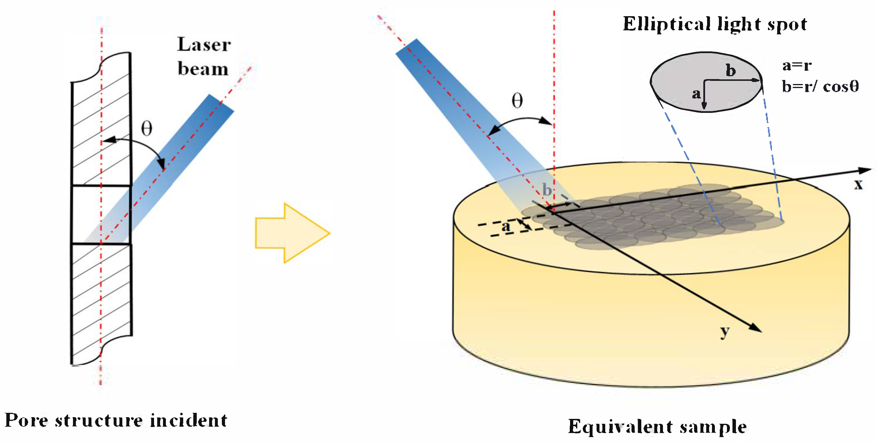
Figure 1. Schematic Diagram of Laser Oblique Impact.
Lubricants 13 00502 g001
Figure 2. (a) Dimensions of the circular specimen (b) Metallographic structure of the original specimen.
Lubricants 13 00502 g002
Figure 3. Ball-disc wear test. (a) Friction and wear testing machine; (b) Principle of ball-disc wear test.
Lubricants 13 00502 g003
Figure 4. Surface morphology at different angles: (a) 0°; (b) 15°; (c) 30°; (d) 45°.
Lubricants 13 00502 g004
Figure 5. Metallographic microstructure at different angles: (a) 0°; (b) 15°; (c) 30°; (d) 45°.
Lubricants 13 00502 g005
Figure 6. Microhardness distribution. (a) Hardness distribution along the cross-section; (b) Surface microhardness and hardened layer depth curve.
Lubricants 13 00502 g006
Figure 7. Residual Stress Distribution Curves. (a) Residual stress distribution at different impact angles; (b) Surface residual compressive stress and depth of influence.
Lubricants 13 00502 g007
Figure 8. Friction coefficients.
Lubricants 13 00502 g008
Figure 9. The average wear depth at different angles.
Lubricants 13 00502 g009
Figure 10. Wear 3D diagram and profile comparison: (a) 0°; (b) 15°; (c) 30°; (d) 45°.
Lubricants 13 00502 g010
Figure 11. Wear test results.
Lubricants 13 00502 g011
Figure 12. Schematic diagram of friction and wear and EDS elemental analysis map: (aa2) Angle 0°; (bb2) Angle 15°; (cc2) Angle 30°; (dd2) Angle 45°.
Lubricants 13 00502 g012
Figure 13. Mechanism diagram of strengthening.
Lubricants 13 00502 g013
Table 1. Chemical composition of H13 steel.
Element wt%
CSiMnCrMoVSP
0.390.830.385.01.220.860.0050.022
Table 2. Laser Shock Process Parameters.
Process ParameterParameter Values
Spot diameter (mm)3
Incidence angle0°, 15°, 30°, 45°
Energy (J)8, 8.2, 9.2, 11.3
Power density (GW/cm2)1.41
Wavelength (nm)1064
Pulse width (ns)20
Overlap rate50%
Disclaimer/Publisher’s Note: The statements, opinions and data contained in all publications are solely those of the individual author(s) and contributor(s) and not of MDPI and/or the editor(s). MDPI and/or the editor(s) disclaim responsibility for any injury to people or property resulting from any ideas, methods, instructions or products referred to in the content.