Article

Assessing Impact of Wheel–Rail Force on Insufficient Displacement of Switch Rail in High-Speed Railway

1
Railway Engineering Research Institute, China Academy of Railway Sciences Co., Ltd., Beijing 100081, China
2
School of Civil Engineering, Beijing Jiaotong University, Beijing 100044, China
3
Graduate Department, China Academy of Railway Sciences, Beijing 100081, China
*
Authors to whom correspondence should be addressed.
Lubricants 2025, 13(11), 497; https://doi.org/10.3390/lubricants13110497
Submission received: 2 July 2025 / Revised: 31 August 2025 / Accepted: 1 September 2025 / Published: 14 November 2025
(This article belongs to the Special Issue Tribological Challenges in Wheel-Rail Contact)

Abstract

High-speed railway turnouts play important roles in the efficient operation of trains. However, the complex mechanical structure of turnouts and insufficient displacement of switch rails under dynamic conditions create a point of vulnerability for high-speed railways. The insufficient displacement of switch rails in high-speed railway No. 18 turnouts critically impacts operational safety. This study establishes a coupled finite element model of the switch rail and sliding track bed plate to analyse the effects of the friction coefficient and wheel–rail force. The results show that without considering the force of the iron block, the maximum insufficient displacement of a switch rail occurs at sleeper No. 27, and the maximum insufficient displacement increases linearly with the friction coefficient, with a regression coefficient of 1.02. When considering the wheel–rail force of the train, the maximum insufficient displacement of the switch rail occurs at sleeper No. 25, with the regression coefficient reduced to 0.67. Through dynamic and static tests and a case analysis, the influence of wheel–rail force on the insufficient displacement of a switch rail is verified. The results show that the application of a lateral wheel–rail force in the model significantly reduces the insufficient displacement of the switch rail, with an improvement of more than 90%. This study can significantly improve the optimisation of turnout design and the operational efficiency of a railway network.

1. Introduction

A turnout in a railway network is used to move a train onto a different track. The structure of turnouts is complex, their maintenance and repair require significant investments, and train speeds are also limited, forming a weak spot in the track [1,2,3]. During actual operation, switch rail conversions often fail as the rail is unable to move to its predetermined position due to stiffness, friction from the slide plate, a reaction with the iron block, close reaction forces, or other factors. The difference between actual and designed displacement is defined as insufficient displacement of the switch rail [4]. The main reason for insufficient displacement of a switch rail is that switch rails are slender rods with low bending stiffness and the tension generated by its elasticity is insufficient to overcome the resistance to motion during conversion, such that bending deformation occurs at a non-traction point [5]. Insufficient displacement of a switch rail indicates that the conversion performance of the switch rail does not meet design requirements, which is a potential hidden danger to traffic safety. At normal-to-intermediate-speed turnouts, insufficient displacement of a switch rail has less influence on the running behaviour of a train passing through the turnout at lower speeds. However, with the increased train speeds on a high-speed turnout, insufficient displacement of a switch rail forces the wheels to change directions abruptly, which seriously affects passenger comfort and the safe operation of a high-speed train passing through the turnout [6,7]. Since 2005, China has begun to develop a series of turnouts for dedicated passenger lines, which have become the most widely used high-speed railway turnouts in the world [8]. When developing a series of turnouts for dedicated passenger lines, the railway engineering department pays special attention to the influence of wheel–rail force on the insufficient displacement of a switch rail at high-speed turnouts. By better understanding how the wheel–rail force affects turnout displacement, the turnout design can be optimised and more suitable materials can be selected to improve the dynamic load resistance of the turnout, prolong its service life, and reduce maintenance requirements. In addition, this research supports the advancement of high-speed railway technology, helps in designing railway systems that can safely cope with higher speeds and more extreme weather conditions, and enhances the overall resilience and reliability of the entire railway network.
To date, many scholars have conducted research on the factors influencing the insufficient displacement of a switch rail. Wang [5,9] used the finite element method to construct a theory for calculating the insufficient displacement of a switch rail and analysed the influence of friction coefficient, conversion mode, the lateral stiffness of the fastener, heel structure, and other factors. The results show that the layout of friction levels and tractive points significantly affects the switch rail. Cai et al. [10,11] studied the influence of various factors on switch rail conversion using ANSYS and a TSSA program. They found that reducing friction and increasing tractive points can effectively reduce the insufficient displacement of switch rails. Chen et al. [12] established a switch rail model for trams using finite element software and discussed factors such as the friction coefficient of the slide plate and the stiffness of the rail close section. The results showed that the maximum insufficient displacement increases linearly with the friction coefficient of the slide plate. Wang et al. [13] used ANSYS to study the influence of turnout force and insufficient displacement on turnout performance. They pointed out that the turnout force can be reduced by reducing the lateral stiffness of the rear heel fastener to address insufficient displacement. Zeng et al. [14] used MIDAS and ANSYS to analyse the influence of the rail heel end rail bottom cutting on the insufficient displacement of rails. Si et al. [15] established a finite element three-dimensional simulation model for the structural characteristics of the new turnout 9 switch rail. They analysed factors such as tractive point conversion and the position of the connecting rod. Ma et al. [16] studied the influence of the pre-bending vector of a switch rail on its insufficient displacement through the factory test.
As for the method of controlling insufficient displacement of a switch rail, the research shows that a reasonable layout of tractive points can significantly reduce insufficient displacements. Jing et al. [17,18] established movable nose rail models of turnout Nos. 18 and 42, analysed the influencing factors of insufficient displacement, and found that the distance between tractive points had a non-linear effect on the insufficient displacement of switch rails, but there was an optimal distance. Su [19] designed four traction layout schemes and analysed their influence on turnouts with large curvature radii, indicating that a reasonable traction layout can significantly improve the conversion performance. Wang et al. [20] optimised the design of traction layouts based on physical information to minimise the insufficient displacement of switch rails. Another effective way to reduce the insufficient displacement of switch rails is to reduce the friction coefficient of the slide plate. Zhang et al. [21] developed a remaining useful life (RUL) prediction method based on improved sparse auto-encoder (ISAE) and gated recurrent unit (GRU) networks to predict railway turnout system (RTS) faults caused by the insufficient displacement of a switch rail and to calculate the optimal prevention threshold based on the predicted RUL. A lot of research has also been conducted based on model construction and setting proprietary devices to effectively control the insufficient displacement of turnouts. Li et al. [22] studied the physical relationship between the size of the turnout gap in the turnout machine and the turnout proximity and proposed evaluating the turnout gap by measuring the turnout gap in the turnout machine. Based on the adaptive correction algorithm, Dutta et al. [23] introduced a closed-loop controller in the joint simulation to automatically adjust insufficient displacement of a switch rail. Wang et al. [24] and Yan et al. [25] designed differential devices and spring transfer devices to reduce the insufficient displacement of switch rails, respectively.
Many scholars have studied the influencing factors and control strategies of insufficient displacement of switch rails through theoretical analyses, simulations, and experimental tests. However, research on the influence of wheel–rail force on the insufficient displacement of a switch rail at high-speed railway turnouts is still insufficient. Studying the impact of the complex dynamic force generated by the high-speed train in the turnout area on the insufficient displacement of a turnout is very important for identifying and preventing potential safety risks under extreme conditions. This research can not only optimise the turnout design and improve the operation efficiency and safety of railway networks, but also helps to promote the innovation of turnout technology and develop high-performance turnout systems that can adapt to higher speeds and larger traffic volumes. In passenger-dedicated and high-speed railway lines, turnout No. 18 is regarded as a core configuration, being particularly suitable for straight-through speeds of 350 km h−1 and diverging speeds of 80 km h−1. For example, single turnouts that connect high-speed main lines to arrival–departure tracks in China are usually equipped with No. 18 turnouts, whereas larger turnouts (e.g., Nos. 24 and 42 turnouts) are deployed only on special high-speed connecting lines; consequently, the proportion of No. 18 turnouts used in high-speed applications is considerably higher. The alignment and principal dimensions of No. 18 turnouts are illustrated in Figure 1. The turnout is equipped with heat-treated 60E1 (UIC 60) plain rails and 60D40 special-section switch rails to satisfy the strength and wear-resistance requirements of curved regions. Prestressed-concrete long bearers (Type I), 2.6–4.2 m in length, are adopted as sleepers. Although most studies have confirmed the positive influence of under-sleeper pads (USPs) on track behaviour [26], no USP is installed in this turnout’s foundation design. Instead, elasticity is provided through the fastening assembly: a Chinese Type-II split-clip system, functionally equivalent to the Vossloh W14 series, fitted with 5 mm rail pads and 20 mm resilient steel baseplates. The ballast bed consists of 45 cm of crushed stone (particle size 25–55 mm) with a shoulder width of at least 45 cm.
In this study, based on finite element software, a switch rail–slide plate coupled simulation analysis model is established for high-speed railway No. 18 turnouts. Insufficient displacement of a switch rail under different friction coefficients is analysed, and the influence of the train wheel–rail force on the insufficient displacement of the switch rail is further discussed. By comparing dynamic and static test results and field verification, this study verifies the effectiveness of the proposed model and explains the insufficient displacement of some turnouts under the dynamic action of trains. An analysis of the dynamic force generated by high-speed trains in the turnout area and its impact on the insufficient displacement of the turnout not only is important for identifying and preventing potential safety risks in the operation of high-speed railways, but can also help to significantly improve the optimisation of turnout design and the operation efficiency of the railway network. The main novel contributions of this study are as follows:
A switch rail–slide plate coupling model is developed which, for the first time, enables dynamic wheel–rail force assessment of insufficient displacement of a switch rail in a No. 18 high-speed turnout.
By examining the influence of wheel–rail forces under different slide plate friction coefficients, the modelling approach is extended to a wider range of operating scenarios, thereby establishing design criteria for surface treatment and lubrication strategies.
The finite-element model is validated at multiple scales using both static and dynamic inspection data, together with on-site verification.
The remainder of this paper is organised as follows: The methodology is introduced in Section 2. The results and discussion are presented in Section 3. A case study is presented in Section 4. Finally, the conclusions are provided in Section 5.

2. Methodology

2.1. Switch Rail–Slide Plate Coupling Model

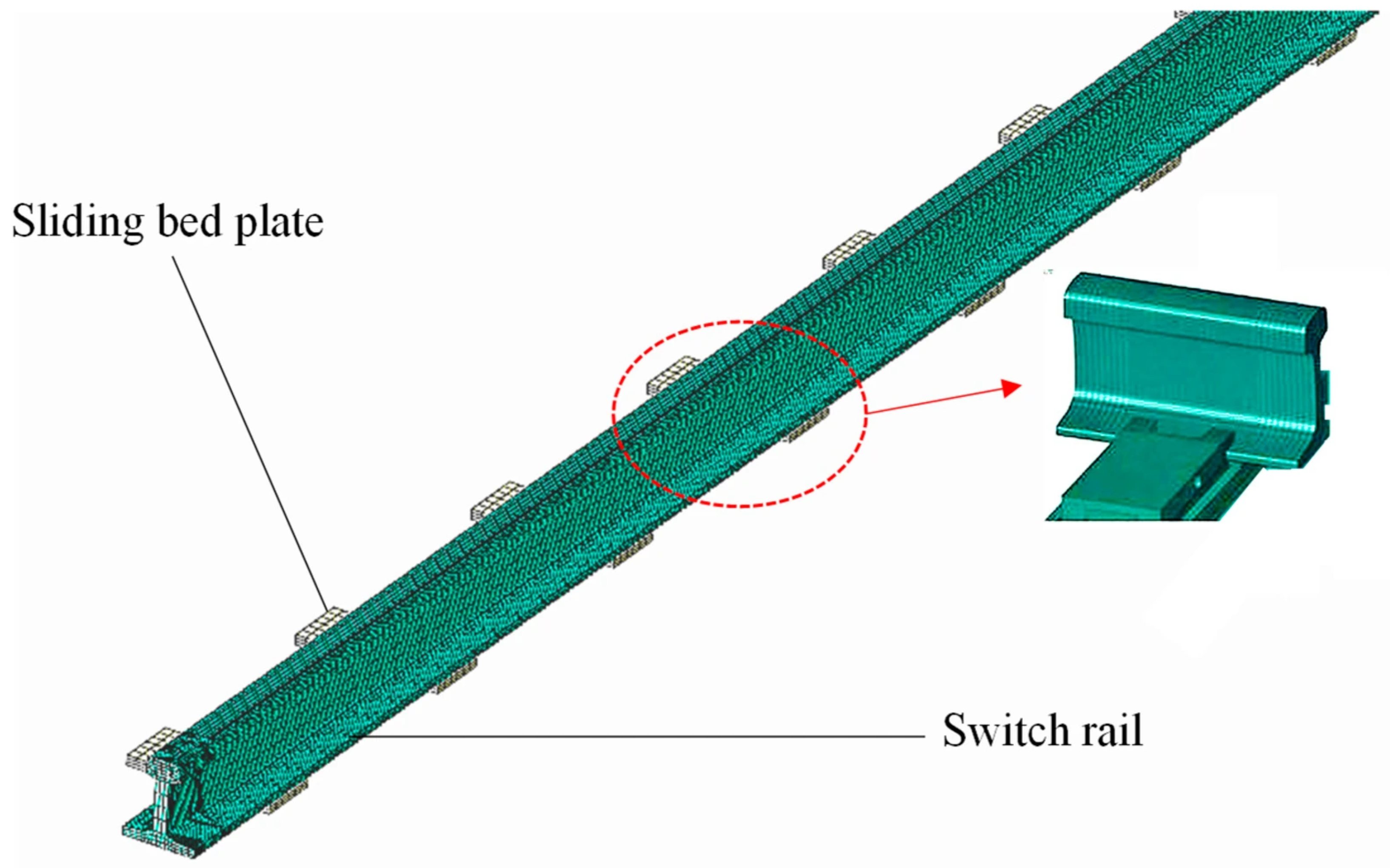
The focus of this study is on the interaction between the switch rail and the slide plate, so the track is simplified as a rigid support beneath the slide plate. The turnout switch rail between the third tractive point and the heel spacer block is modelled together with its corresponding slide plate. The length of the switch rail model is 8.10 m and includes 14 slide plates whose dimensions match the in-service hardware. These slide plates, together with the prestressed long bearers to which they are bolted, create a support and contact system that does not exist in ordinary tracks. A diagram of the overall model is shown in Figure 2. The finite element analysis in this study was performed using ANSYS 2021 R1.
Both the switch rail and the slide plate adopt isotropic materials without considering the plastic deformation of the structure. The switch rail material is U75V, and the slide plate adopts Q235A. Specifically, the switch rail has a density of 7790 kg/m3, an elastic modulus of 206 GPa, and a Poisson’s ratio of 0.3; the slide plate has a slightly higher density of 7850 kg/m3, an elastic modulus of 210 GPa, and the same Poisson’s ratio of 0.3.
Mesh generation in finite element software involves mesh seed, element shape, and mesh generation technology. The mesh seed directly determines the number of meshes. As the number of meshes increases, the finite element calculation results become more accurate, but the calculation time also increases. In this study, a mesh independence analysis is conducted to ensure the accuracy of the finite element model while balancing computational efficiency. Given the complexity of the turnout and the slide plate, the mesh size plays a critical role in determining both the precision of the results and the computational cost. The mesh size for the turnout is set to 5 mm to ensure high accuracy in regions of significant deformation, such as the switch rail and contact areas, allowing for precise capture of the non-linear contact behaviour between the switch rail and the slide plate, as well as the stress distribution within the turnout structure. The mesh size for the slide plate is set to 10 mm, as the deformation in the slide plate is generally smaller, and a coarser mesh can still provide reliable results while improving computational efficiency. By using these mesh sizes, the model effectively balances computational time and the required accuracy. The element shapes include quadrilateral, triangle, tetrahedron, hexahedron, and wedge shapes. For the three-dimensional switch rail–slide plate coupling simulation model, the accuracy of the hexahedral element calculation is higher. Therefore, the grid type of the rail and the slide plate is C3D8R, a three-dimensional eight-node hexahedral element with good stress and deformation analysis ability. The mesh generation technology includes a swept, accessible, and structured grid. The shape of the coupling simulation model established in this paper is relatively simple and suitable for structured grid generation technology.
This study uses ‘face-to-face contact’ to simulate the interaction between the switch rail and the slide plate. In the ‘face-to-face contact’, there are two contact pairs: the main surface and the surface. Generally, the surface with more significant stiffness is selected as the main surface when the master and slave surfaces are selected. Considering that the stiffness of the switch rail and the slide plate are not very different, the slide plate with coarse mesh density is chosen as the main surface. During the interaction simulation, the direction of the force is always perpendicular to the main plane, and the main plane node is allowed to penetrate the slave plane, while the slave plane node cannot penetrate the main plane.
Considering that the relative displacement between the switch rail and the slide plate is large, the finite slip effect is selected in the calculation. Normal contact between the switch rail and the slide plate is simulated through the contact stiffness, and the tangential contact is simulated through the penalty function. This study conducts a sensitivity analysis of boundary conditions to evaluate their impact on the results. First, a fixed boundary condition is applied at the bottom of the slide plate in the model to simulate the real-world scenario where the slide plate is fixed at the bottom. Secondly, a displacement constraint of 71 mm is applied to the free end of the switch rail, consistent with operational conditions. These analyses ensure the robustness of the model under different boundary conditions and validate the appropriateness of the selected boundary conditions. In addition, when the lateral load of the train is applied, the lateral support effect is applied to the side of the rail.

2.2. Calculation Method

The interaction between the switch rail and the slide plate exhibits boundary non-linearity, as their contact interface evolves with loading and deformation. Consequently, the problem of insufficient switch rail displacement must be treated as a non-linear static analysis. After finite-element discretisation, the governing equations become a system of non-linear algebraic equations that can be solved through a variety of numerical schemes, including iterative, incremental, and combined incremental–iterative methods. In purely iterative approaches, the original non-linear equations are recast into iterative forms that repeatedly refine an initial linearised solution until convergence is achieved. Common variants include the simple (direct) iteration, the Newton–Raphson algorithm, and its modified form. The direct iteration method is straightforward to implement and widely used, but it may suffer from numerical instability when the problem is highly non-linear. The Newton–Raphson algorithm employs first- and second-order derivatives of the residual to converge rapidly towards the solution, yet its performance is highly sensitive to the choice of initial estimate; appropriate selection of the starting point, step size, and convergence tolerance is therefore essential in practice. The modified Newton–Raphson method updates the tangent stiffness matrix only during the first or a few early iterations, reducing computational cost at the expense of a slower convergence rate. In incremental schemes, the external load is divided into several increments. At each load step, a small load increase is applied, and the corresponding increase in displacement is superimposed to obtain the total response. When incremental and iterative strategies are combined, the non-linear equilibrium equations are solved iteratively within each load increase, providing both robustness and accuracy for complex railway turnout analyses.
The convergence speed of the iterative method is fast, but the convergence is not stable. The convergence of the incremental method is good, but the convergence speed is slow. The incremental iteration method can combine the advantages of the above two methods and divide the calculation process into multiple incremental steps. In each incremental step, the iterative method is used for the calculations, ensuring calculation efficiency and convergence. In this study, the non-linear statics problem of switch rail–slide plate coupling is solved using the incremental iteration method combined with the Newton–Raphson algorithm. The calculation assumptions are as follows:
The direction of the slide plate’s friction force is opposite to the direction of the movement of the switch rail, and its value is proportional to the weight of the rail above the slide plate, which does not change with the change in the rail displacement.
The centre of the third tractive point of the switch rail is the free-moving end, and the interval iron of the heel end is assumed to be the rigidly fixed end.
In the initial state, the switch and basic rails are in a close state. By moving the free-moving end, the switch rail changes from the close state to the repulsive state and then moves from the repulsive state to the free-moving end. Due to the influence of friction, the gap between the switch and stock rails is caused by insufficient displacement of the switch rail.

3. Results and Discussion

The friction coefficient range of μ = 0.25–0.4 was selected based on experimental and field data. For typical slide plates in railway turnouts, the dynamic friction coefficient varies between 0.2 and 0.3, depending on the lubrication state of the surface. This range is cited in previous studies as representing the common frictional behaviour of switch rails under operational conditions [27]. During the operation of turnouts, particularly during the locking and unlocking processes, the switch rail slides on the slide plate. To ensure proper functionality, the slide plate allows for a certain degree of slippage, with the friction coefficient typically less than 0.3 in existing turnout configurations [28]. However, the slide plate experiences rusting due to exposure to weather, causing an increase in the friction coefficient and resulting in a greater insufficient displacement of the switch rail. To assess the impact of corrosion, the analysis also considers scenarios where the friction coefficient of the slide plate increases to 0.4.
Since the switch rail and movable nose rail have no lateral support in the section where the insufficient displacement occurs, when the flange contacts the non-close rail, the switch rail is subjected to lateral force from the train. The lateral force exerts a force opposite to the direction of the friction force, which can offset the insufficient displacement of some switch rails. To evaluate the influence of the train’s lateral force on the insufficient displacement of the switch rail under different friction coefficients, the lateral force is applied to the maximum insufficient displacement of the switch rail when the friction coefficients of the slide plate are 0.25, 0.3, and 0.4. In summary, to evaluate the influence of different friction coefficients on the maximum insufficient displacement of the switch rail and the elimination effect of the train’s lateral force on the insufficient displacement, six working conditions were considered, as shown in Table 1.

3.1. Analysis of Insufficient Displacement of Switch Rail Under Different Friction Coefficients

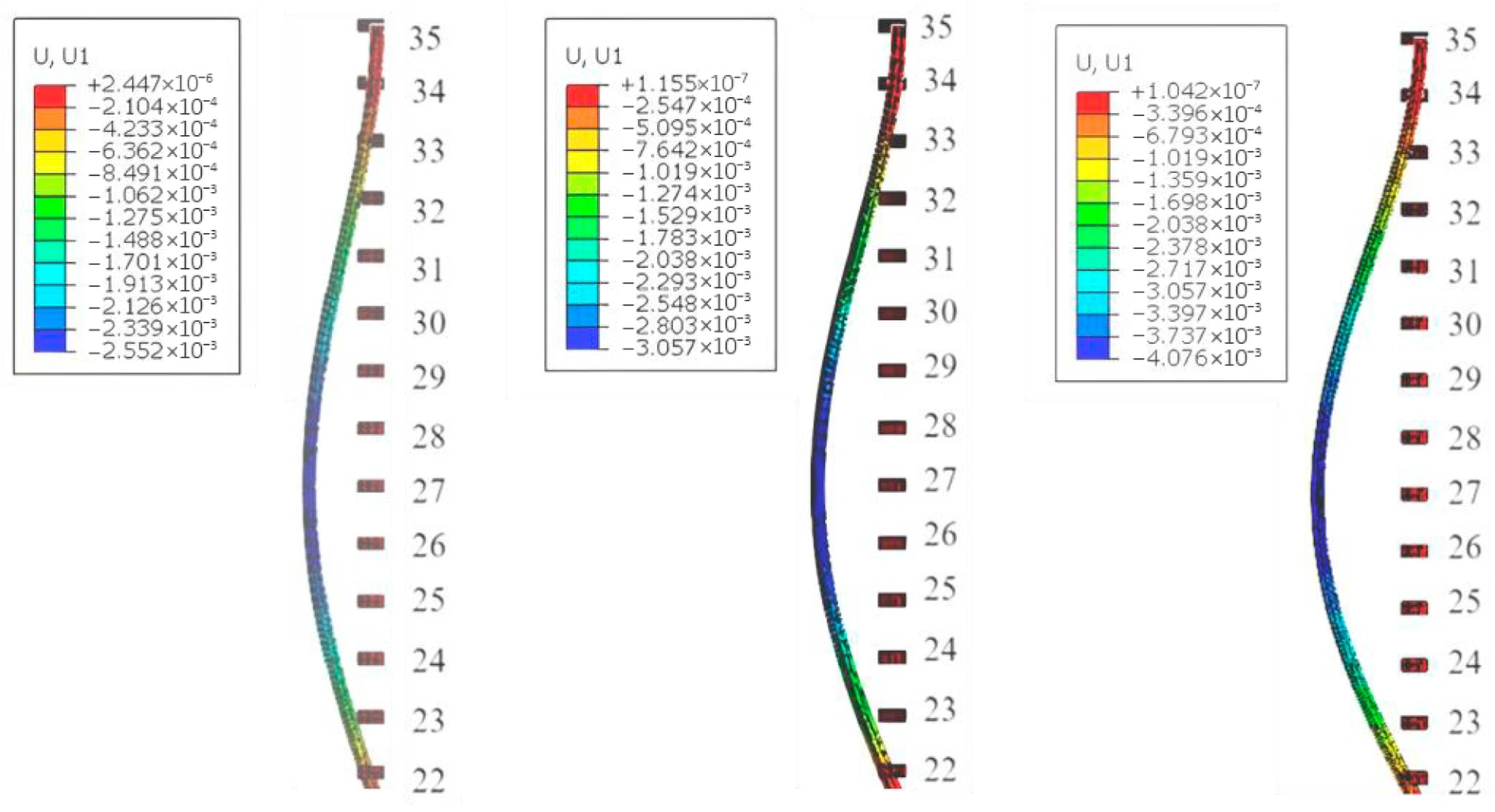
The displacement and cloud diagrams of the switch rail for friction coefficients of 0.25, 0.3, and 0.4 are shown in Figure 3.
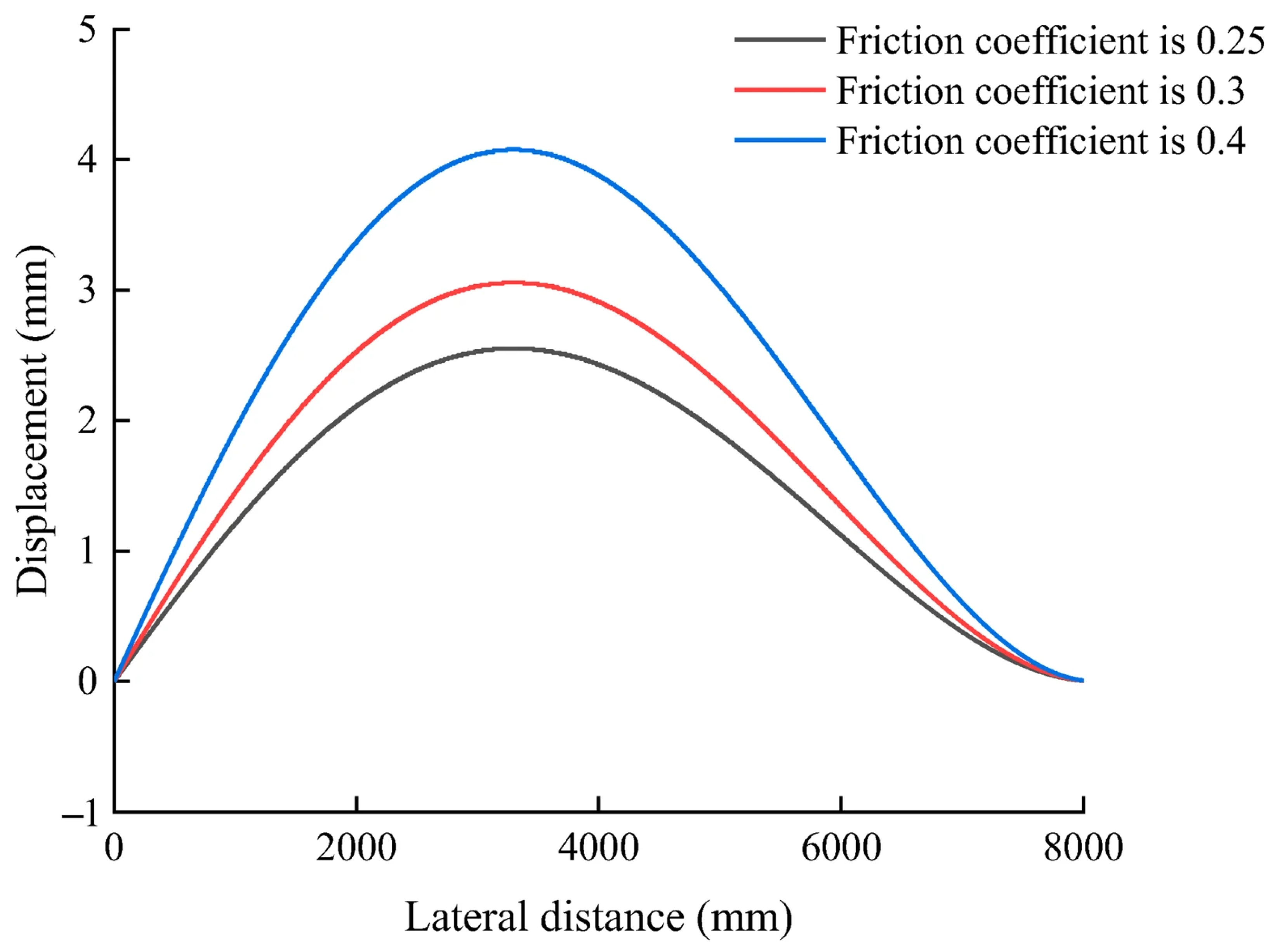
As shown in Figure 3, when the friction coefficient increases from 0.25 to 0.4, the switch rail has a more obvious displacement, indicating that the higher the friction level between the switch rail and the slide plate, the greater the stress and insufficient displacement of the switch rail. It is worth noting that under different friction coefficients, the maximum insufficient displacement of the switch rail occurs at sleeper No. 27. Further, this paper studies the variation in lateral insufficient displacement values of the switch rail under different friction coefficients, as shown in Figure 4.
As shown in Figure 4, the deformation of the switch rail first increases and then decreases along the lateral distance. When the friction coefficient increases from 0.25 to 0.30, the maximum insufficient displacement of the switch rail increases from 2.55 mm to 3.06 mm, an increase of 20.00%. When the friction coefficient increases from 0.30 to 0.40, the maximum insufficient displacement of the switch rail increases from 3.06 mm to 4.08 mm, an increase of 33.33%. To further analyse the relationship between the maximum insufficient displacement of the switch rail and the friction coefficient, this work used a fitting function to obtain the relationship; see Figure 5.
As shown in Figure 5, the maximum insufficient displacement of the rail increases linearly with the increase in friction coefficients, with a regression coefficient of 1.02. To further verify the linear relationship, five fully independent finite-element simulations (with randomised mesh generation and initial contact perturbations) were carried out at each of the three friction levels (μ = 0.25, 0.30, 0.40), yielding a total of 15 maximum insufficient displacements of the switch rail, as summarised in Table 2.
As shown in Table 2, the five independent finite-element runs at each friction-coefficient level yielded within-group standard deviations of no more than 0.045 mm and coefficients of variation below 2%, indicating a high degree of consistency. Moreover, the mean value rose by roughly 0.51 mm as the friction coefficient increased from 0.25 to 0.30 and by a further 1.02 mm when it increased from 0.30 to 0.40, revealing a clear linear growth trend.

3.2. Analysis of Insufficient Displacement of Switch Rail Under Wheel–Rail Force
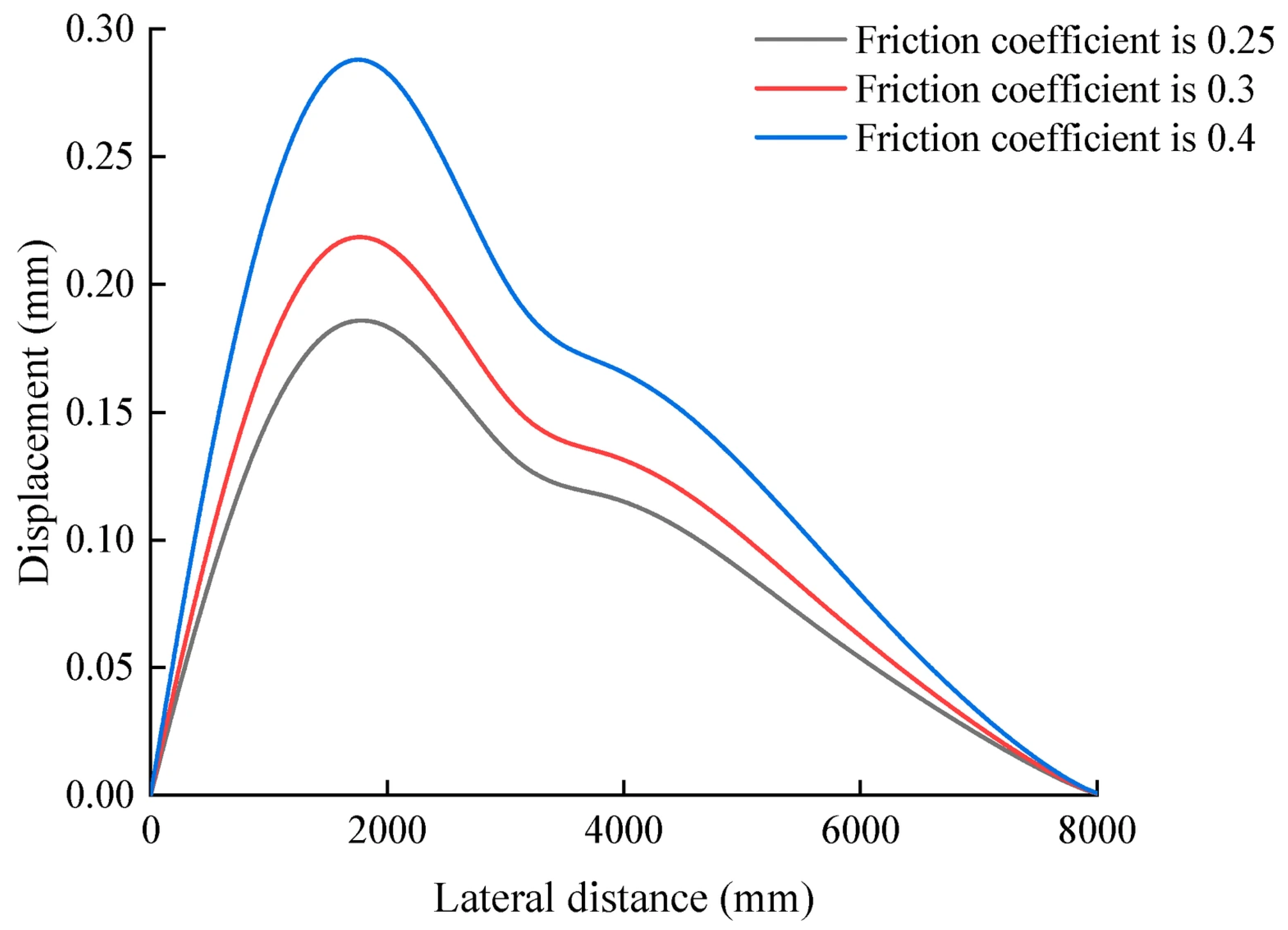
The vehicle dynamic loads were applied based on the wheel–rail forces derived from the dynamic calculations. Specifically, a lateral wheel–rail force of 5 kN (representing the force when a train passes through the switch rail) was applied to the static model. This approach allowed for a detailed analysis of the switch rail and sliding bed plate interaction under realistic loading conditions while keeping the computational model focused and manageable. The variation law for insufficient displacement of the switch rail under the action of lateral wheel–rail force is shown in Figure 6.
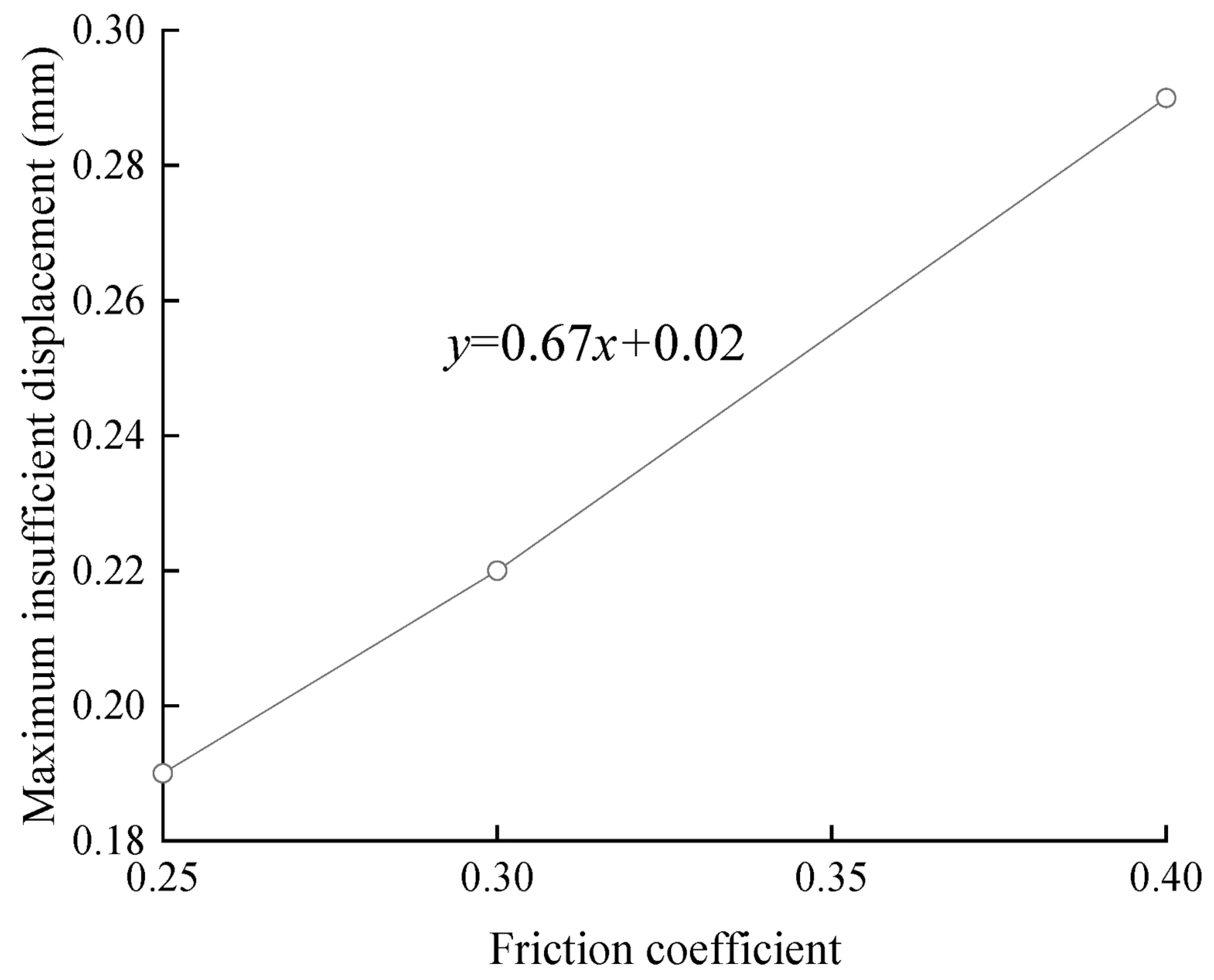
As shown in Figure 6, insufficient displacement of the switch rail is significantly reduced under the influence of lateral wheel–rail force compared with the insufficient displacement in Figure 4. Under different friction coefficients, the deformation of the switch rail first increases. Then, it decreases laterally, and the maximum displacement occurs correspondingly at sleeper No. 25. When the friction coefficients are 0.25, 0.3, and 0.4, respectively, the maximum insufficient displacement of the switch rail is 0.19 mm, 0.22 mm, and 0.29 mm. As shown in Table 3, the maximum displacement of the switch rail under different friction coefficients is reduced by about 90% compared with under conditions with no later wheel–rail force.
Figure 7 shows the relationship between the maximum insufficient displacement of the switch rail and the friction coefficient with lateral force applied. Similarly to the working condition without lateral wheel–rail force, the maximum insufficient displacement of the switch rail increases linearly with the increase in the friction coefficient, with a regression coefficient of 0.67.
Figure 7. Relationship between friction coefficient and maximum insufficient displacement of switch rail under influence of lateral wheel–rail force.
Lubricants 13 00497 g007
To further verify the linear relationship, five fully independent finite-element simulations (with randomised mesh generation and initial contact perturbations) were carried out at each of the three friction levels (μ = 0.25, 0.30, 0.40) under the influence of wheel–rail force, yielding a total of 15 values for maximum insufficient displacement of the switch rail, as summarised in Table 4.
As shown in Table 4, the five independent finite-element simulations at each friction-coefficient level produce within-group standard deviations no greater than 0.00071 mm and coefficients of variation below 2%, demonstrating excellent repeatability. Furthermore, the mean maximum insufficient displacement increases by approximately 0.03 mm as μ rises from 0.25 to 0.30 and by a further 0.07 mm when μ increases from 0.30 to 0.40, confirming a clear linear growth trend.

4. Case Study

4.1. Evaluation Standard for Improvement

When assessing insufficient displacement of the switch rail, if the difference between the gauge value detected with a dynamic track inspection car and the data measured using a track inspection instrument at the same position is less than or equal to 0.5 mm, it is regarded as no improvement. If the gauge value detected with the track inspection car is 0.5 to 2 mm larger than the data measured using the track inspection instrument, the gauge value is considered to have improved. When the difference is greater than 2 mm, the gauge values show obvious improvement. The dynamic track inspection car tests were conducted at a speed of 300 km/h, typical for train speeds when passing through a straight-through turnout, with a load equivalent to passenger trains (axle weight of 14–17 t). Static measurements were performed using a track inspection instrument under conditions of no train passage, allowing for a comparison with the dynamic results. These conditions reflect the real-world operational environment and typical loading scenarios.

4.2. Comparison of Static and Dynamic Inspection Results

In this study, 38 groups of turnouts with maximum insufficient displacement values exceeding 2 mm were selected for analysis, including 25 groups of turnout A and 13 groups of turnout B. The measurement data from the dynamic track inspection car and track inspection instrument were compared, and the results are shown in Table 5.
As shown in Table 5, when the train passes through the turnout dynamically, 2 groups show no improvement, 7 groups show improvement, and 16 groups show obvious gauge improvement in turnout A, with those showing improvement making up 92%. When the train passes through the turnout dynamically, 1 group shows no improvement, 1 group shows improvement, and 11 groups shows obvious gauge improvement in turnout B, with those showing improvement making up 92.3%. The above results show that under the influence of wheel–rail force, the switch rail can effectively adjust its position to adapt to the change in turnout force, thus reducing the maximum insufficient displacement.

4.3. On-Site Verification

The No. 18 turnout of station C is a turnout on the left side of an arrival–departure ballast track line. On 8 August 2023, the gauge of the turnout in the range of sleeper Nos. 23~34 before and after the curved strand conversion was detected using the track inspection instrument. To compare the maximum insufficient displacement of the switch rail under the influence of the train’s wheel–rail force, on 22 August 2023, the gauge in the range of sleeper Nos. 23 to 34 was detected using a dynamic rail inspection car. The results of the comparison of static and dynamic measurements for the No. 18 turnout of station C is shown in Table 6.
As shown in Table 6, gauge measurements for sleeper Nos. 23 to 34 at station C’s No. 18 turnout were initially recorded between −2.5 mm and 0.8 mm using a track inspection instrument, with the largest deviation observed at sleeper No. 31, registering −2.5 mm. Following three cycles of back-and-forth conversions, the gauge range shifted to between −7.0 mm and −0.8 mm. This alteration in gauge values ranged from a minimum of 0.5 mm to a maximum of 6.1 mm, with the most significant changes recorded for sleeper Nos. 27 and 28, each showing a displacement of 6.1 mm. The smallest change was observed for sleeper No. 34, with a modification of 0.5 mm. Additional assessments using a dynamic track inspection vehicle indicated initial gauge measurements in the same sleeper range from 1.8 mm to 0.7 mm before the conversion. After the conversion, these measurements changed to between 1.5 mm and 5.9 mm, with the greatest alterations noted for sleeper Nos. 27 and 28, measuring 5.9 mm and 5.8 mm, respectively, and the smallest change again for sleeper No. 34, with a 1.5 mm adjustment. The above results show little difference between the dynamic and static measurement results before and after the conversion of sleeper Nos. 23 to 30 for a No. 18 turnout in station C. However, the difference in dynamic and static measurements for sleeper Nos. 31 to 34 before and after the conversion is more significant, indicating that under the influence of the train’s wheel–rail force, insufficient displacement of the switch rail can be significantly improved.

5. Conclusions

The No. 18 turnout has become the most widely used high-speed railway turnout in the world. However, during actual operation, large insufficient displacement occurs in the switch rail of this turnout, affecting driving safety and stability. In this study, the change in insufficient displacement of the switch rail under different friction coefficient conditions was analysed by establishing a switch rail–slide plate coupled simulation analysis model. On this basis, the influence of wheel–rail force on insufficient displacement of the switch rail was further studied. By comparing the test results of the dynamic inspection car with the track inspection instrument, the following conclusions were obtained:
Without considering the force of the iron block, the maximum insufficient displacement of the switch rail appears correspondingly at sleeper No. 27. The deformation of the switch rail first increases and then decreases laterally. The maximum insufficient displacement of the switch rail increases linearly with the increase in friction coefficient, with a regression coefficient of 1.02.
Under the influence of lateral wheel–rail force, the insufficient displacement of the switch rail is partially offset. The maximum insufficient displacement of the switch rail is transferred correspondingly from sleeper No. 27 to sleeper No. 25. The maximum insufficient displacement of the switch rail increases linearly with the increase in friction coefficient, with a regression coefficient of 0.67 after the offset.
Comparing the data measured using the dynamic track inspection car and the track inspection instrument, insufficient displacement of the switch rail exceeding 2 mm is found to improve under the influence of the train’s wheel–rail force, with the improvement ratio reaching more than 90%.

Author Contributions

P.W.: Supervision, Funding acquisition, Writing—Review and Editing; L.H.: Writing—Original Draft; X.W.: Formal analysis, Investigation, Visualisation; D.Y.: Data Curation, Methodology, Investigation, Visualisation; D.S.: Software, Investigation, Visualisation; M.Z.: Investigation, Visualisation; S.W.: Writing—Review and Editing; G.J.: Writing—Review and Editing. All authors have read and agreed to the published version of the manuscript.

Funding

This research was funded by the Science and Technology Research Project of CHINA RAILWAY (N2023G078) and the Scientific Research Project of China Academy of Railway Sciences Corporation Limited (2022YJ177).

Data Availability Statement

The data are not available due to restrictions.

Conflicts of Interest

Authors Pu Wang, Dongsheng Yang, Daolin Si, Moyan Zhang and Shuguo Wang were employed by the company Railway Engineering Research Institute, China Academy of Railway Sciences Co., Ltd. The remaining authors declare that the research was conducted in the absence of any commercial or financial relationships that could be construed as a potential conflict of interest.

References

  1. Jing, G.; Siahkouhi, M.; Qian, K.; Wang, S. Development of a field condition monitoring system in high speed railway turnout. Measurement 2021, 169, 108358. [Google Scholar] [CrossRef]
  2. Cai, X.; Tang, X.; Yang, F.; Wang, T.; Sun, J. Estimation of turnout irregularities using vehicle responses with improved BiLSTM and Gaussian process regression. Measurement 2023, 221, 113513. [Google Scholar] [CrossRef]
  3. Wang, F.; Wang, A.; Tang, T.; Shi, J. SGL-PCA: Health Index Construction with Sensor Sparsity and Temporal Monotonicity for Mixed High-Dimensional Signals. IEEE Trans. Autom. Sci. Eng. 2023, 20, 372–384. [Google Scholar] [CrossRef]
  4. Wang, P.; Zhao, Z.; Ma, J.; Wang, S. Study on the optimization of high-speed turnout crossing structures based on actual elastic deformation of point and splice rails. Proc. Inst. Mech. Eng. Part F J. Rail Rapid Transit 2023, 238, 141–151. [Google Scholar] [CrossRef]
  5. Wang, P.; Chen, R.; Xu, H. Conversion and its deviation control of electric switch machine of high speed railway turnout. J. Vibroeng. 2013, 15, 1513–1525. [Google Scholar]
  6. Xu, J.; Zhu, X.; Wang, X.; Chen, R.; Wang, P.; Liu, B.; Luo, Y. Fatigue damage analysis of the straight switch rail considering complex random loads. Veh. Syst. Dyn. 2023, 61, 2394–2414. [Google Scholar] [CrossRef]
  7. Wang, P.; Chen, R.; Chen, X. Key technologies in high-speed railway turnout design. China Railw. 2022, 8, 1–7. [Google Scholar] [CrossRef]
  8. Wang, P.; Wang, S.G.; Wang, M.; Zhao, Z.H.; Si, D.L.; Ma, S.Y.; Sun, Z.L. Number selection and structural optimization of 400 km/h high-speed turnout. J. Traffic Transp. Eng. 2023, 23, 114–126. [Google Scholar] [CrossRef]
  9. Wang, P. Computation and analysis of the switchingpower by multipoint traction. Railw. Stand. Des. 2002, 46, 23–25. [Google Scholar]
  10. Cai, X.; Li, C. Study on controlling the switching force and scant displacement of the point rail of the high speed turnout. J. China Railw. Soc. 2008, 30, 48–51. [Google Scholar]
  11. Cai, X. A Study on the Switching and Its Controlling of the Switch and Nose Rails in High Speed Turnout. Ph.D. Thesis, Southwest Jiaotong University, Chengdu, China, 2008. [Google Scholar]
  12. Chen, M.; Liu, C.; Wang, P. Finite element analysis of switch rail conversion for no.6 turnout in the streetcar line. Railw. Eng. 2017, 58, 135–137. [Google Scholar]
  13. Wang, B.; Wang, P.; Xie, K.; Wang, L.; Quan, S. Analysis of Influence Factors of Switching Force and Inadequate Displacement of Switch Rail of NO.9 Turnout. Appl. Mech. Mater. 2012, 226–228, 872–876. [Google Scholar] [CrossRef]
  14. Zeng, R.; Wang, S.; Wang, P.; Yang, L. FEM Simulation Analysis About Influence of Rail Bottom Slicing on Switch Rail Transformation. Railw. Eng. 2019, 59, 140–142+146. [Google Scholar]
  15. Si, D.; Zhao, Z.; Wang, S. Study on switching characteristics of switch rail for No.9 turnout of new 50 kg·m−1 rail. China Railw. Sci. 2021, 42, 27–33. [Google Scholar]
  16. Ma, H.; Wang, C. Experimental analysis and control of inadequate displacement of turnout switch rail. Railw. Qual. Control 2017, 45, 41–45. [Google Scholar]
  17. Jing, G. Analysis of No.18 Moveable-Turnoutinsufficient Displacement. Master’s Thesis, Southwest Jiaotong University, Chengdu, China, 2006. [Google Scholar]
  18. Jing, G. ANSYS simulation analysis of No.18 moveableturnout insufficient displacement. Railw. Eng. 2007, 47, 108–110. [Google Scholar]
  19. Su, X. Analysis of Insufficient Switch Rail Displacement of High-Speed Turnout. Master’s Thesis, Lanzhou Jiaotong University, Lanzhou, China, 2013. [Google Scholar]
  20. Wang, F.; Sun, S.; Cao, Y.; Pei, Y.; Tang, T. Optimal Design of Tractive Layout for Minimizing the Insufficient Displacement of Railway Turnout. IEEE Trans. Intell. Transp. Syst. 2023, 24, 12597–12613. [Google Scholar] [CrossRef]
  21. Zhang, Y.; Cheng, Y.; Xu, T.; Wang, G.; Chen, C.; Yang, T. Fault Prediction of Railway Turnout Systems Based on Improved Sparse Auto Encoder and Gated Recurrent Unit Network. IEEE Trans. Intell. Transp. Syst. 2021, 23, 12711–12723. [Google Scholar] [CrossRef]
  22. Li, C.; Zhao, L. A Railway Turnout Closeness Monitoring Method Based on Switch Gap Images. IEEE Intell. Transp. Syst. Mag. 2022, 14, 214–229. [Google Scholar] [CrossRef]
  23. Dutta, S.; Harrison, T.; Ward, C.P.; Dixon, R.; Scott, T. A new approach to railway track switch actuation: Dynamic simulation and control of a self-adjusting switch. Proc. Inst. Mech. Eng. Part F J. Rail Rapid Transit 2019, 234, 779–790. [Google Scholar] [CrossRef]
  24. Wang, P.; Ma, X.-C.; Wang, J.; Xu, J.-M. Effect on the scant displacement of switch rail of high-speed turnout by the differential motion device. J. Railw. Eng. Soc. 2015, 32, 43–48. [Google Scholar]
  25. Yan, Q.; Sun, X.; Yang, S.; Zhang, L. Study of Spring Transfer Drive Device for Scant Displacement of Switch Rail. Railw. Signal. Commun. 2017, 53, 28–31. [Google Scholar]
  26. Kraśkiewicz, C.; Anysz, H.; Zbiciak, A.; Płudowska-Zagrajek, M.; Al Sabouni-Zawadzka, A. Artificial neural networks as a tool for selecting the parameters of prototypical under sleeper pads produced from recycled rubber granulate. J. Clean. Prod. 2023, 405, 136975. [Google Scholar] [CrossRef]
  27. Chen, L. Research on Failure Mechanism and Damage Recognition Algorithm of Turnout Slide Plate in Alpine Region. Master’s Thesis, Lanzhoou Jiaotong University, Lanzhou, China, 2023. [Google Scholar]
  28. Luo, Y.; Xu, Y. Investigation of Dry Bearings in Railway Switch Slide Baseplate. J. Shanghai Tiedao Univ. (Nat. Sci. Ed.) 1998, 10, 41–46. [Google Scholar]
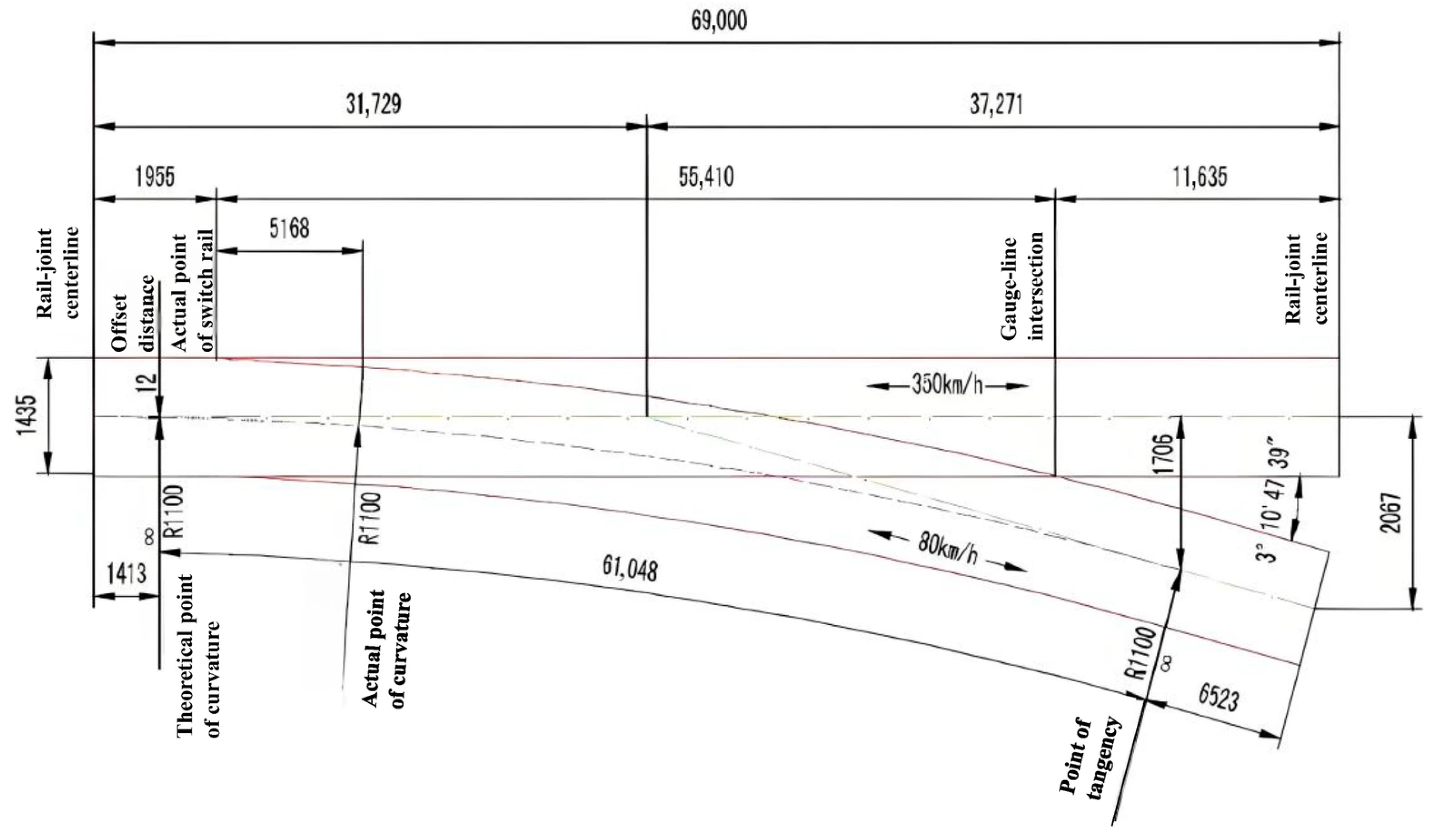
Figure 1. Schematic diagram of the alignment and main dimensions of No. 18 turnouts.
Lubricants 13 00497 g001
Figure 2. Switch rail–slide plate coupling model.
Lubricants 13 00497 g002
Figure 3. Deformation cloud (magnification factor: 300).
Lubricants 13 00497 g003
Figure 4. Change in insufficient displacement of switch rail under different friction coefficients.
Lubricants 13 00497 g004
Figure 5. Relationship between friction coefficient and maximum insufficient displacement of switch rail.
Lubricants 13 00497 g005
Figure 6. Change in insufficient displacement of switch rail under the influence of lateral wheel–rail force.
Lubricants 13 00497 g006
Table 1. Working conditions.
Working ConditionFriction CoefficientWheel–Rail Force Applied
10.25No
20.3No
30.4No
40.25Yes
50.3Yes
60.4Yes
Table 2. Statistical results of repeated tests on maximum insufficient displacement of switch rail at three friction levels.
Friction CoefficientMaximum Insufficient
Displacement/mm
Mean/mmStandard Deviation/mmCoefficient of Variation/%
Test 1Test 2Test 3Test 4Test 5
0.252.482.562.542.572.602.550.0451.8
0.303.003.083.053.103.073.060.0381.2
0.404.024.054.094.114.124.080.0421.0
Table 3. Maximum displacement of the switch rail under different friction coefficients.
Friction CoefficientMaximum Insufficient
Displacement Without
Wheel–Rail Force/mm
Maximum Insufficient
Displacement with
Wheel–Rail Force/mm
Displacement Reduction/mmPercentage Reduction in Displacement/%
0.252.550.192.3692.55
0.303.060.222.8492.81
0.404.080.293.7992.89
Table 4. Statistical results of repeated tests on the maximum insufficient displacement of switch rail at three friction levels under the influence of wheel–rail force.
Friction CoefficientMaximum Insufficient
Displacement/mm
Mean/mmStandard Deviation/mmCoefficient of Variation/%
Test 1Test 2Test 3Test 4Test 5
0.250.1890.1900.1900.1900.1910.1900.000710.37
0.300.2200.2200.2200.2210.2200.2200.000450.20
0.400.2900.2900.2910.2900.2900.2900.000450.15
Table 5. Comparison of measurement data from dynamic track inspection car and track inspection instrument.
TurnoutNo ImprovementImprovementObvious ImprovementTotal NumberImprovement Proportion
A27162592.0%
B11111392.3%
Table 6. Comparison of static and dynamic measurements for No. 18 turnout of station C.
Sleeper NumberResults of Track Inspection Instrument Before Conversion/mmResults of Track Inspection Instrument After Conversion/mmDifference Between Results of Two Track Inspection Instruments/mmResults of Dynamic Track Inspection Car/mmDifference Between Static and Dynamic Measurement Result/mm
D23−1.80.72.50.22.0
D24−3.00.83.70.33.3
D25−4.20.74.90.54.7
D26−5.40.35.70.25.6
D27−6.4−0.36.1−0.55.9
D28−7.0−0.96.1−1.25.8
D29−6.9−1.45.5−1.85.1
D30−6.2−1.94.3−1.44.8
D31−5.0−2.52.5−1.63.4
D32−3.7−2.51.2−1.12.6
D33−2.4−1.80.6−0.32.1
D34−0.8−0.30.50.71.5
Disclaimer/Publisher’s Note: The statements, opinions and data contained in all publications are solely those of the individual author(s) and contributor(s) and not of MDPI and/or the editor(s). MDPI and/or the editor(s) disclaim responsibility for any injury to people or property resulting from any ideas, methods, instructions or products referred to in the content.