Article

Tribological Properties of Aluminum–Silicon Alloy Cylinder Liners Paired with DLC and CKS Piston Rings

Xinyu Key Laboratory of Materials Technology and Application for Intelligent Manufacturing, Xinyu University, Xinyu 338004, China
*
Author to whom correspondence should be addressed.
Lubricants 2025, 13(11), 487; https://doi.org/10.3390/lubricants13110487
Submission received: 6 October 2025 / Revised: 28 October 2025 / Accepted: 4 November 2025 / Published: 6 November 2025

Abstract

With the increasing demand for energy conservation and emission reduction in the automotive industry, optimizing the performance of cylinder liner and piston ring pairs in engines has become crucial. Aluminum–silicon alloy cylinder liners, known for their lightweight and excellent thermal conductivity, have emerged as a new trend in cylinder liner materials. Given the relatively moderate hardness of Al-Si alloys, judicious selection of piston rings is imperative to ensure optimal performance. This study investigates the tribological properties of aluminum–silicon alloy cylinder liners paired with CKS and DLC piston rings. The surface morphology and hardness of the test materials were characterized, and reciprocating friction and wear tests were conducted, using a tribometer to simulate operating conditions. The friction coefficient and wear volume were used as indicators to evaluate the tribological properties of the piston rings. The results show that, when the aluminum–silicon alloy cylinder liner was paired with a DLC piston ring, the friction coefficient was 27.82% lower, and the wear volume of the cylinder liner was 83.52% lower, compared to pairing with a CKS piston ring. When paired with a CKS piston ring, wear was exacerbated because silicon particles were easily dislodged to form abrasive particles. This particle detachment is mainly caused by the collision between the fine ceramic particles embedded in the CKS coating and the silicon particles (≤5 μm) uniformly distributed in the Al-Si alloy cylinder liner during the sliding process. The DLC piston ring, containing both sp2 and sp3 hybridized carbon–carbon bonds, combined excellent lubrication properties with high hardness, resulting in minimal wear on both the cylinder liner and piston ring. Specifically, the DLC coating has a hardness of 2300 HV0.3, which is 2.42 times that of the CKS piston ring (950 HV0.3); the sp3-hybridized carbon in the DLC coating enhances its wear resistance to resist scratching from silicon particles in the cylinder liner, while the sp2-hybridized carbon forms a graphite-like transfer layer at the friction interface to reduce frictional resistance. In conclusion, the aluminum–silicon alloy cylinder liner paired with a DLC piston ring exhibits superior tribological properties. Selecting an appropriate piston ring can significantly enhance the tribological properties of the cylinder liner–piston ring pair, thereby extending the engine’s service life.

1. Introduction

With the continuous advancement of technology, automobiles have become an indispensable means of transportation in our daily lives. This has led to increasing demands for energy conservation and emission reduction in the automotive industry, as well as higher requirements for engine reliability, durability, and environmental friendliness. In the field of large internal combustion engines, reducing fuel consumption, increasing power density, and achieving CO2 targets constitute the primary driving forces behind the development of new engines. This necessitates an in-depth understanding of the mechanisms governing piston ring–cylinder liner pairs, while also considering the quantities and compositions of lubricants. Given that a significant portion of frictional energy loss in internal combustion engines occurs in the piston group, the piston ring–cylinder liner system offers substantial potential for improvement [1]. The friction and wear behaviors of the cylinder liner and piston ring pair in engines are critical factors affecting the overall performance and service life of the engine. Friction losses between the piston ring and cylinder liner account for approximately half of total mechanical friction losses [2]. Optimizing the performance of the cylinder liner and piston ring pair can significantly enhance engine efficiency and extend its lifespan. Therefore, studying the tribological properties of cylinder liners against piston rings is of great importance.
Aluminum–silicon alloy cylinder liners, compared to traditional cast iron liners, are lighter in weight and feature hard silicon particles uniformly distributed on their surface, which contribute to reduced friction and improved wear resistance. These advantages have made aluminum–silicon alloy cylinder liners a new trend in cylinder liner materials [3]. Despite their benefits, such as lightweight properties, excellent thermal conductivity, and consistent thermal expansion coefficients, aluminum–silicon alloy cylinder liners have lower hardness compared to conventional cast iron liners. This makes them more susceptible to wear when paired with piston rings, thereby imposing higher requirements on the surface treatment processes of the piston rings [4,5].
In the development of surface treatment technologies for piston rings, chromium-based ceramic composite coating (Chrom–Keramik–Schicht, CKS) is a novel coating formed by embedding nano-ceramic particles into a hard chromium layer through a layered deposition process. This method leverages the inherent micro-crack characteristics of chromium to enhance the coating’s properties [6]. CKS coatings have been widely applied in piston ring surface treatments, significantly improving the wear resistance and corrosion resistance of piston rings, while substantially reducing friction losses [7]. Ma Siqi et al. [8] investigated the wear performance and anti-scuffing properties of CKS-coated piston rings paired with CuNiCr cast iron cylinder liners. Their experiments revealed that the crown offset ratio had no significant effect on the friction coefficient. When the crown offset ratio was 32%, the CKS piston rings exhibited excellent anti-scuffing performance. Thomas Markut et al. [1] developed an application-oriented reciprocating model test system to investigate the scuffing behavior of CKS-coated piston rings. Their findings revealed that vertical cracks arise from residual stresses, while horizontal cracks are induced by shear stresses. Additionally, iron acts as a catalyst for tribopad formation on the CKS layer, and zinc sulfides are not universally present. They further verified that the model test system can effectively simulate the damage mechanisms of actual engines.
However, with the advancement of surface treatment technologies, diamond-like carbon (DLC) coatings have gradually become a research hotspot due to their unique properties and excellent friction-reducing and wear-resistant effects [9,10]. DLC coatings are typically prepared using physical vapor deposition (PVD) methods. These coatings exhibit characteristics of both diamond and graphite, and, when applied to piston rings, they often contain C-H hybrid phases, usually in an amorphous state or with partial nanocrystalline structures [11]. DLC-coated piston rings are known for their high hardness, low friction coefficient, and excellent chemical stability [12]. Wan et al. conducted tribological property studies on electroplated Cr coatings, Cr-Al2O3 coatings, and Cr-diamond coatings under oil-lubricated conditions using a high-frequency reciprocating friction tester. The study revealed that the electroplated Cr-diamond coating exhibits sufficient hardness under extreme-pressure conditions. Moreover, under insufficient lubrication, it undergoes a phase transformation from diamond to graphite, which enhances its anti-scuffing capability and durability compared to electroplated Cr and Cr-Al2O3 coatings [13]. Wang Yanrong et al. [14] designed interrupted wear tests under lean oil conditions to investigate the tribological matching behavior between diamond-like carbon (DLC) piston rings and boron–phosphorus (BP) alloy cast iron cylinder liners in high-power-density diesel engines. The results showed that the DLC coating exhibited excellent tribological properties, with low friction coefficients and small wear loss at 150 °C and 240 °C. Specifically, when paired with the BP cylinder liner, material transfer was not observed for up to 77 min under starved lubrication and even unlubricated conditions, demonstrating outstanding scuffing resistance. Moreover, the formation of a tribo-chemical carbide layer could effectively suppress significant adhesive wear, even with temporary fluctuations in friction force. Notable contributions have been made by previous studies: Wang et al. [14] effectively demonstrated the scuffing resistance of DLC piston rings when paired with cast iron cylinder liners, and Ferreira et al. [15] provided valuable insights into optimizing DLC coating topography for friction reduction. However, Wang et al.’s work was limited to cast iron substrates and did not involve Al-Si alloy cylinder liners, while Ferreira et al. ignored the interaction between DLC coatings and protruding silicon particles in Al-Si alloys. A key research gap remains, in that no systematic comparison of CKS and DLC piston rings paired with Al-Si alloy cylinder liners under simulated engine TDC conditions (260 °C, 20 MPa) exists. This study aims to fill this gap.
While the aforementioned studies on piston rings primarily focused on the performance of the coatings themselves, and their compatibility with cast iron cylinder liners, they did not address the performance of these coatings when paired with aluminum–silicon alloy cylinder liners. In practical applications, it is essential to determine whether CKS piston rings or DLC piston rings exhibit better compatibility with aluminum–silicon alloy cylinder liners. Therefore, this study investigates the tribological properties of aluminum–silicon alloy cylinder liners paired with DLC and CKS piston rings. The findings are of significant importance for enhancing the reliability and durability of aluminum–silicon alloy cylinder liners in service and advancing the development of internal combustion engine technologies.

2. Experimental Materials and Methods

2.1. Experimental Materials

2.1.1. Aluminum–Silicon Alloy Cylinder Liner

The main chemical components of the Al-Si alloy cylinder liner are shown in Table 1.
The cylinder liner specimens were prepared by wire electrical discharge machining (WEDM) from the original Al-Si alloy cylinder liner (inner diameter: 132 mm). The surface roughness (Ra) of the cylinder liners was 1.0 μm. The cut specimens had rectangular dimensions of 42 mm × 8 mm × 6 mm. Prior to experiments, all specimens were ultrasonically cleaned in gasoline and ethanol sequentially for 20 min each to remove residual cutting fluid and debris, then dried with a cold-air blower. The honing pattern on the surface of the aluminum–silicon alloy cylinder liner used in the experiment is shown in Figure 1. As observed, the honing texture on the cylinder liner surface is clear, dense, and uniformly distributed, with smooth transitions between the grooves and plateaus. The cylinder liner exhibits numerous fine honing marks, with a honing angle of 45°.
After the cut specimens were prepared, grinding was conducted as follows: First, manual rough grinding was performed using 400-grit waterproof sandpaper with uniform pressure applied; water cooling was carried out every 30 s, and the edges of the specimens were chamfered to a radius of approximately 1 mm. Subsequently, fine grinding was conducted in the order of 800-grit → 1200-grit → 1500-grit sandpaper; the grinding direction of the specimens was rotated by 90° each time the sandpaper was replaced, until only uniform grinding marks in a single direction remained on the surface. Then, mechanical polishing was performed using a metallographic polishing machine; the polishing disc rotation speed was set to 400 r/min, and polishing was carried out on a flannelette polishing disc with 7 μm and 1.5 μm diamond polishing pastes in sequence. After polishing, the specimens were rinsed with absolute ethanol and dried with cold air. Next, the polished specimens were immersed in 4% nitric acid–ethanol solution for corrosion at room temperature, at a corrosion duration of 15–20 s; after corrosion, the specimens were rinsed, dehydrated with absolute ethanol, and then dried with cold air. Finally, observation was conducted using an optical microscope (Olympus Corporation, Tokyo, Japan).
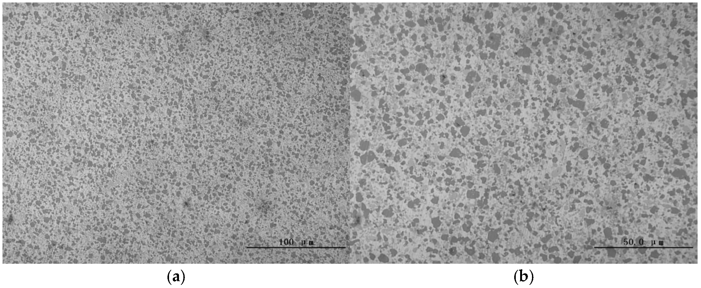
The microstructure of the aluminum–silicon alloy cylinder liner was observed after polishing (Figure 2). The silicon particles were fine and uniformly distributed, with no apparent defects at the interface between the silicon particles and the aluminum matrix. All of the silicon particles present on the surface were diminutive in size, with the largest ones measuring approximately 5 microns in diameter.
The inner surface of the cylinder liner sample was polished, and the surface microhardness was measured using an Everone MH-6 microhardness tester under a load of 300 g and a dwell time of 10 s. Five experiments were conducted, and the resulting measurements are presented in Table 2. Following a thorough calculation, the average microhardness of the aluminum–silicon alloy cylinder liner was determined to be 428 HV0.3. The fine silicon particles contribute to the enhanced hardness of the Al-Si alloy.

2.1.2. Piston Rings

The piston rings used in the experiment were CKS piston rings and DLC piston rings. The CKS piston rings were chromium-based ceramic composite-coated rings, with a measured microhardness of 950 HV0.3. The DLC coating had a hardness of 2300 HV0.3, which is 2.42 times higher than that of the CKS piston rings. The surface roughness (Ra) of the CKS piston rings was 0.4 μm, and that of the DLC piston rings was 0.3 μm.
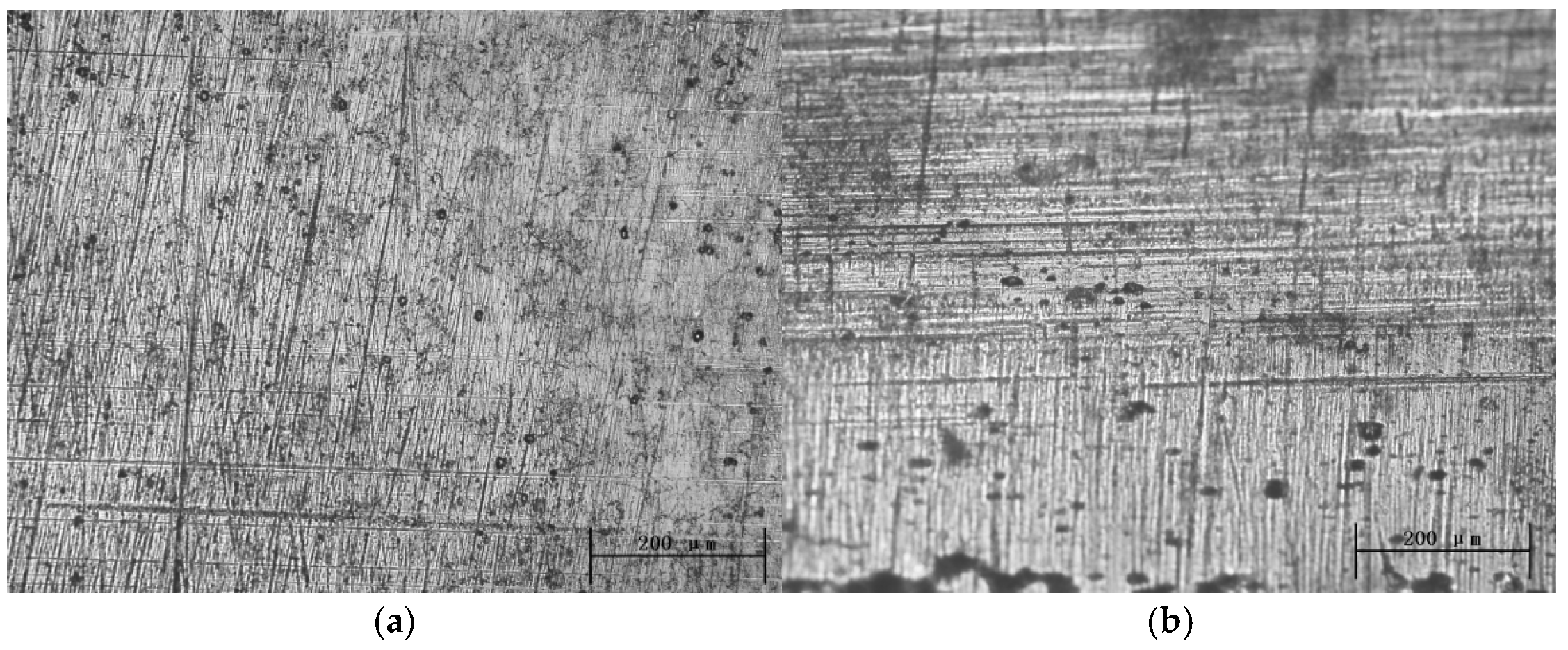
Figure 3 shows the surface morphology of the two types of piston rings. Both the CKS and DLC rings exhibit machining marks on their surfaces. After surface polishing, fine ceramic particles embedded in the chromium-based coating of the CKS rings can be observed, while no cracks are found on the polished surface of the DLC ring, indicating good coating quality.
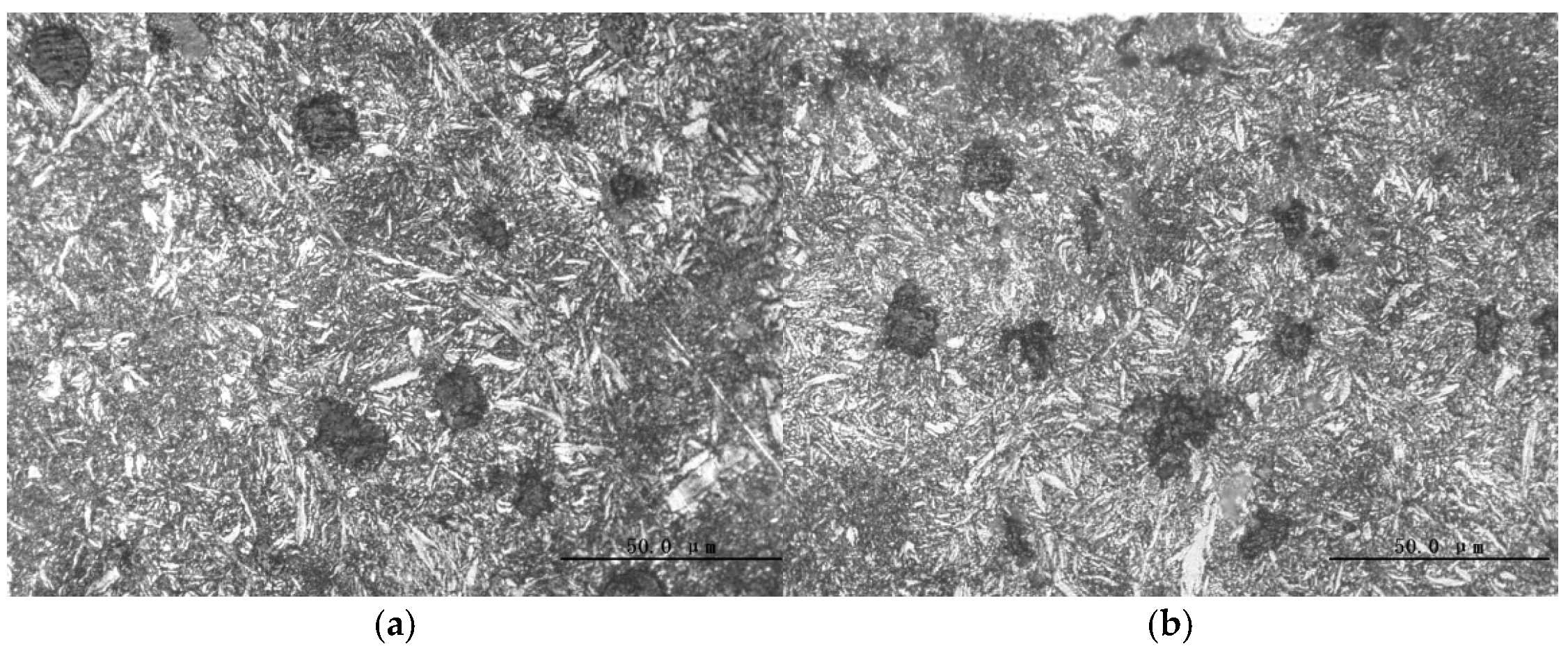
The piston ring samples were ground, polished, and etched with 4% nitric acid alcohol. The observation area was within 1 mm from the inner surface of the cross-section (Figure 4). The matrices of both piston rings were nodular cast iron, with a uniform distribution of tempered martensite.
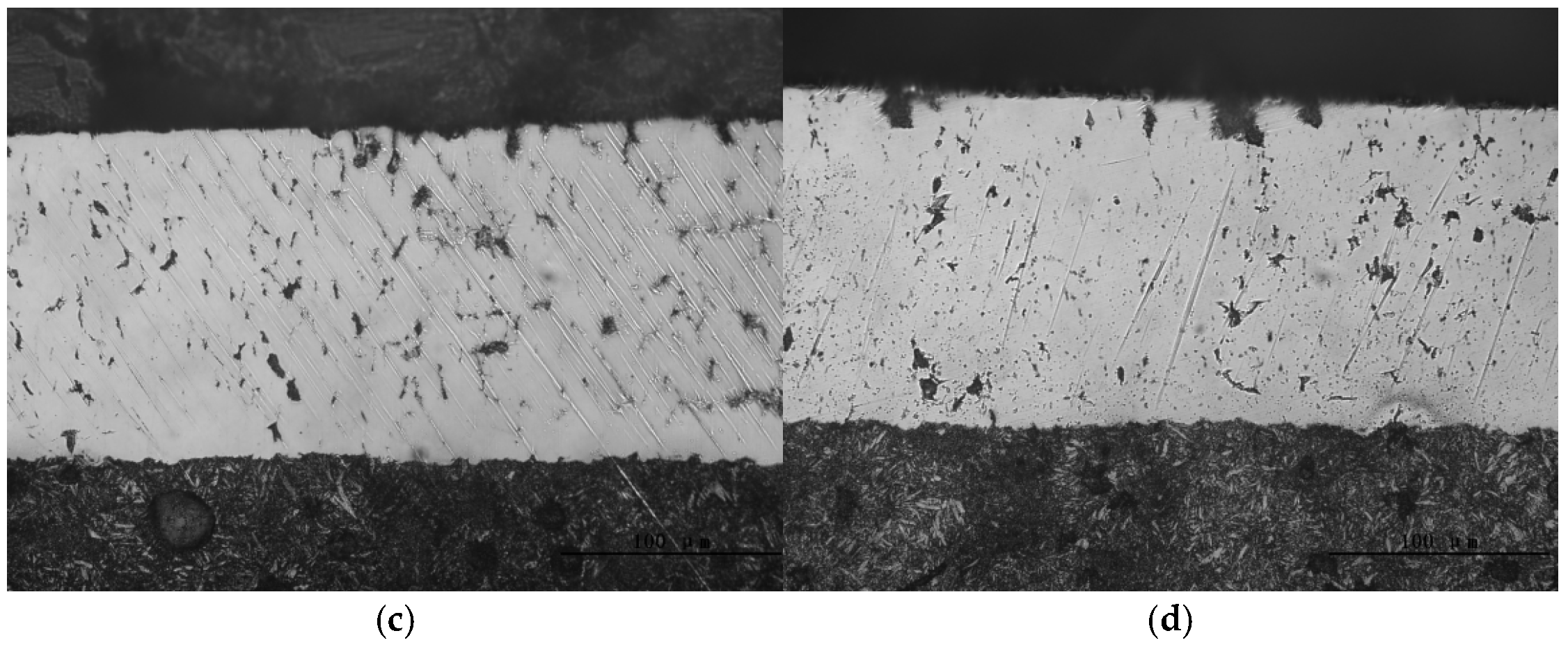
Figure 5 shows the cross-sectional morphology of the piston ring coatings and the bonding state between the coatings and the substrate (Figure 5a,b). The coating thickness is non-uniform. The maximum coating thickness (Tmax) on the working surface of the CKS ring is approximately 167 μm, while that of the DLC ring is about 150 μm. The maximum coating thickness of the CKS ring is slightly greater than that of the DLC ring. The bonding states between the coatings and the substrates of the two piston rings are shown in Figure 5c,d. It can be observed that both coatings exhibit good bonding with the substrates, with a natural transition and tight adhesion, free from defects such as voids or cracks.

2.2. Experimental Methods

2.2.1. Experimental Equipment

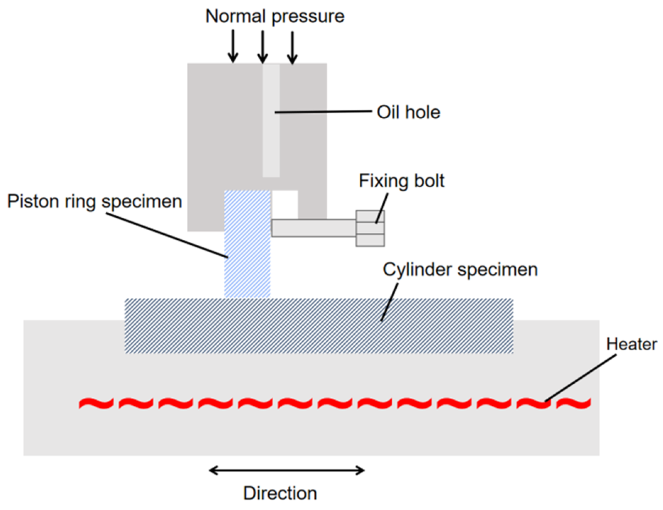
The aluminum–silicon alloy cylinder liner adopts a tailored composition with 20% Si, 5 wt.% Fe, 2 wt.% Ni, 3 wt.% Cu, 2 wt.% Mn, 1 wt.% Mg, and <1 wt.% V (Al as balance); distinct from conventional Al-Si alloys, this high-silicon and multi-alloy design not only enhances the dispersion of fine silicon particles (≤5 μm in diameter, as shown in Figure 2), but also improves the surface hardness to 428 HV0.3 (Table 2) while maintaining good thermal conductivity, effectively addressing the trade-off between the wear resistance and lightweight properties of Al-Si cylinder liners reported in prior studies. The tribological tests were performed using a self-developed opposed reciprocating tribometer (Figure 6), which was specifically customized to simulate the reciprocating motion of the piston ring–cylinder liner pair and the high-temperature, high-pressure conditions near the engine top dead center (TDC); by adjusting the relative sliding speed and applying gradient loads, this device can accurately replicate the boundary lubrication state consistent with real engine TDC conditions, ensuring the reliability of the test results.
A reciprocating friction and wear testing machine was used to simulate the reciprocating motion of the piston ring–cylinder liner pair and the working temperature near the top dead center (TDC). The relative sliding speed between the piston ring and cylinder liner samples was reduced to achieve boundary lubrication conditions. Under these conditions, accelerated wear was induced by applying increased loads. The contact configurations of the testing machine are presented in Figure 6.

2.2.2. Experimental Plan

This test program was divided into a running-in stage and a steady-state wear stage. During the break-in stage, three sets of test parameters were employed, all involving a rotational speed of 200 r/min and a temperature of 120 °C. The pressures employed corresponded to 5 MPa, 10 MPa, and 15 MPa. Each set of tests was conducted for a period of 1 h. The test parameters for the stable wear stage were 200 r/min, 260 °C, 20 MPa, and 21 h. By setting different parameters for each stage, the tribological properties were studied. In order to better compare the application states of the two piston rings, this experiment accelerated wear compared to actual working conditions. Therefore, the operating parameters differed from actual working conditions, such as speed reduction and appropriate increases in temperature to accelerate wear [16]. However, the motion form simulated the top dead center position of actual working conditions. Therefore, the results of this experiment can provide theoretical guidance for selecting piston rings in engine applications, improve the service life of engine components, and enhance the reliability of service.
(a)
Speed Selection:
Under normal conditions, when the diesel engine is at the top dead center (TDC) of the cylinder liner, the lubrication state of the cylinder liner–piston ring pair is boundary lubrication, due to the influence of the in-cylinder combustion pressure and the low instantaneous linear velocity of the piston ring. Wear is more severe under these conditions. Wear tests at different speeds have shown that, when the speed is too high, hydrodynamic lubrication effects increase, reducing wear. Conversely, when the speed is too low, wear efficiency decreases due to low linear velocity. Therefore, for accelerated wear testing, a speed of 200 rpm was selected to simulate the boundary lubrication state of the cylinder liner–piston ring pair at TDC in a real diesel engine [16].
(b)
Temperature Selection:
The working temperature of the first compression ring in an internal combustion engine is approximately 200 °C. To accelerate wear, the test temperature was set to 260 °C.
(c)
Load Selection:
A gradient loading method was adopted, starting with a lower target load. After multiple preliminary tests, the running-in stage load was set to start at 5 MPa and increase stepwise, while the steady-state wear stage load was set to 20 MPa.
(d)
Wear Test Duration:
Under the above conditions, measurable wear could be achieved within 24 h. The final test conditions are summarized in Table 3.
Table 3. Test parameters of tribological properties.
Test StageTest Parameters
Running-in Stage200 r/min 120 °C 5 MPa 1 h
200 r/min 120 °C 10 MPa 1 h
200 r/min 120 °C 15 MPa 1 h
Steady-State Wear Stage200 r/min 260 °C 20 MPa 21 h
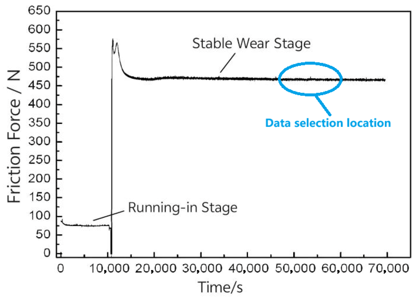
The friction coefficient was used to characterize the relative friction properties of each pair. All experiments were repeated at least four times, and the average of the maximum friction force over 1000 reciprocating cycles was divided by the normal pressure to obtain the friction coefficient. The friction force values were taken from a portion of the stable wear area towards the back (Figure 7), and the wear volume was determined by measuring the mass difference (averaged from repeated tests) of the cylinder liner and piston ring samples before and after the test, using a Mettler AL204-IC electronic balance (Mettler-Toledo GmbH, Greifensee, Switzerland) (accuracy: 0.1 mg). The surface morphology before wear was observed using an OLYMPUS-GX51 metallographic microscope (Olympus Corporation, Tokyo, Japan), while the post-wear morphology was examined using a field emission scanning electron microscope (FE-SEM, ZEISS-SUPRA 55 SAPPHIRE, Carl Zeiss AG, Oberkochen, Germany).

3. Results and Analysis

3.1. Friction Performance

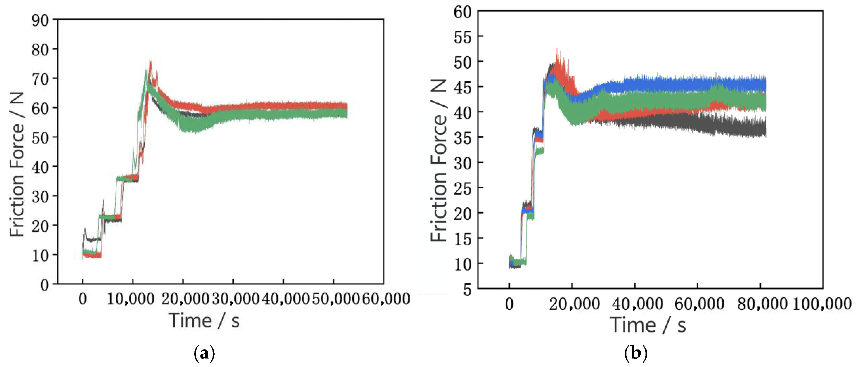
In order to enhance comprehension of the relationship between friction and time for the two sets of paired pairs of vices, four separate experiments were conducted. Figure 8 shows the variation in friction force over time for the two pairs during the friction and wear tests. As observed, during the steady-state wear stage, the average friction force for the aluminum–silicon alloy cylinder liner–CKS ring pair stabilized at approximately 59 N, while that for the aluminum–silicon alloy cylinder liner–DLC ring pair stabilized at around 43 N. The friction force for the aluminum–silicon alloy cylinder liner–DLC ring pair was significantly lower.
The friction coefficients for the two pairs are shown in Figure 9. When the cylinder liner is paired with the DLC piston ring, the friction coefficient is 0.096, while it is 0.133 when paired with the CKS piston ring. The friction coefficient for the aluminum–silicon alloy cylinder liner–DLC ring pair is 27.82% lower than that for the aluminum–silicon alloy cylinder liner–CKS ring pair, indicating superior friction performance for the DLC piston ring.

3.2. Wear Volume Analysis

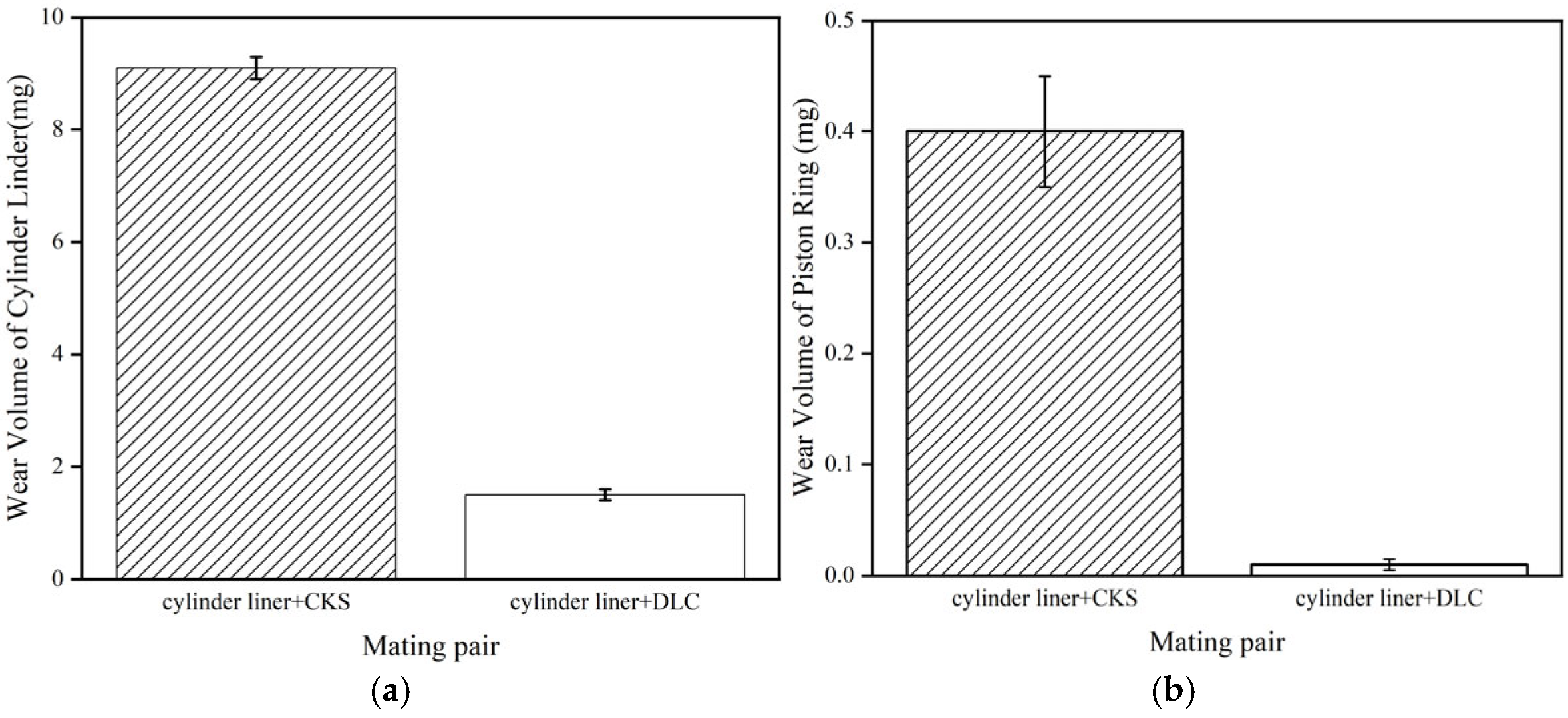
Figure 10 shows the wear volumes for the two pairs. the wear volume of the cylinder liner (Figure 10a). The average wear volume for the aluminum–silicon alloy cylinder liner paired with the CKS ring is 9.1 mg, while it is 1.5 mg when paired with the DLC ring. The wear volume for the aluminum–silicon alloy cylinder liner paired with the DLC ring is significantly lower, reduced by 83.52% compared to that with the CKS piston ring.
The wear volumes of the piston rings are shown in Figure 10b. The wear volumes for both piston rings are relatively small. Specifically, the wear volume for the CKS ring paired with the aluminum–silicon alloy cylinder liner is 0.4 mg, while the DLC ring exhibits almost no wear when paired with the aluminum–silicon alloy cylinder liner, indicating minimal wear for the DLC ring.

3.3. Worn Surface Morphology

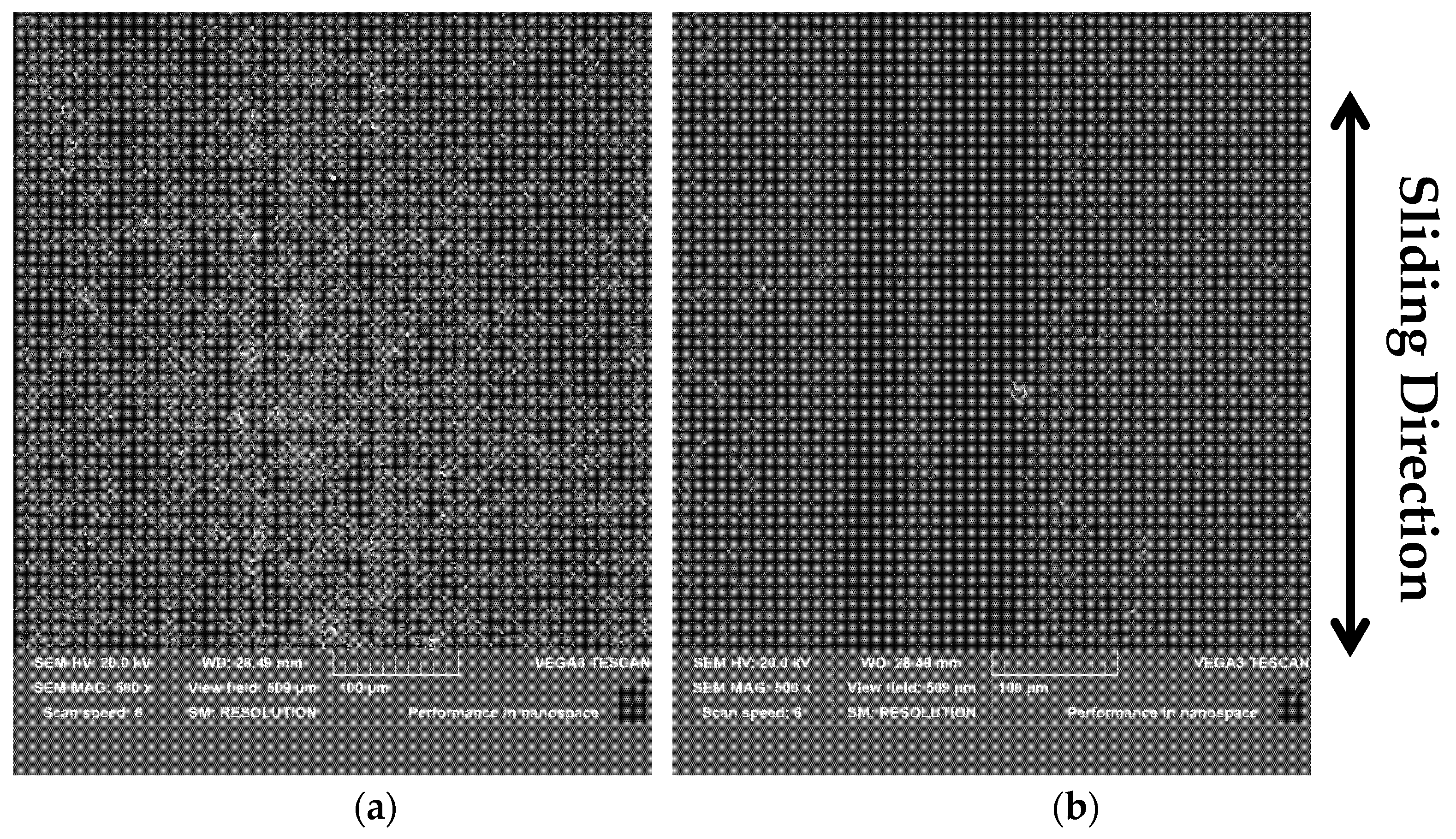
The worn surface morphology of the cylinder liner for the two pairs is shown in Figure 11. The honing marks on the aluminum–silicon alloy cylinder liner paired with the CKS ring disappeared (Figure 11a). Scratches along the vertical sliding direction are observed, along with numerous pits caused by the detachment of silicon particles. The honing marks on the aluminum–silicon alloy cylinder liner paired with the DLC ring also disappeared (Figure 11b). Scratches along the vertical sliding direction are visible, but the worn surface is relatively smooth.
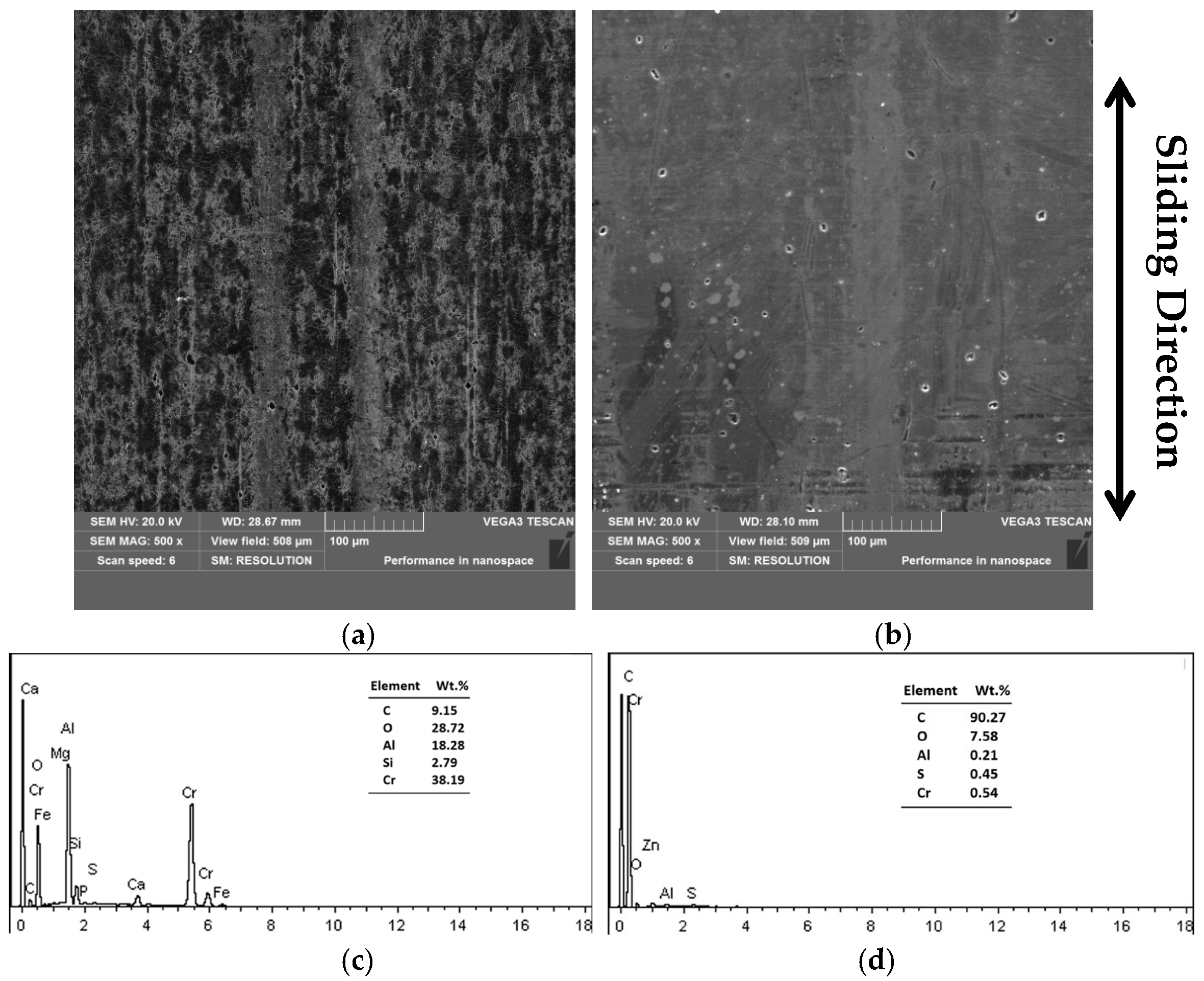
The worn surface morphology of the piston rings for the two pairs is shown in Figure 12. The worn surface of the CKS ring paired with the aluminum–silicon alloy cylinder liner is severely worn. The original transverse machining marks were worn away, and distinct plowing marks along the vertical sliding direction are observed, along with noticeable detachment traces (Figure 12a). In contrast, the wear surface of the DLC ring is relatively smooth, with minimal wear, and some of the original transverse machining marks remain (Figure 12b). The EDX results show that there is a significant transfer of Al elements from the cylinder liner to the worn surface of the CKS ring (Figure 12c), indicating that adhesive wear occurred. However, the wear surface of DLC rings has less elemental Al (Figure 12d) and less adhesion.

3.4. Wear Mechanism

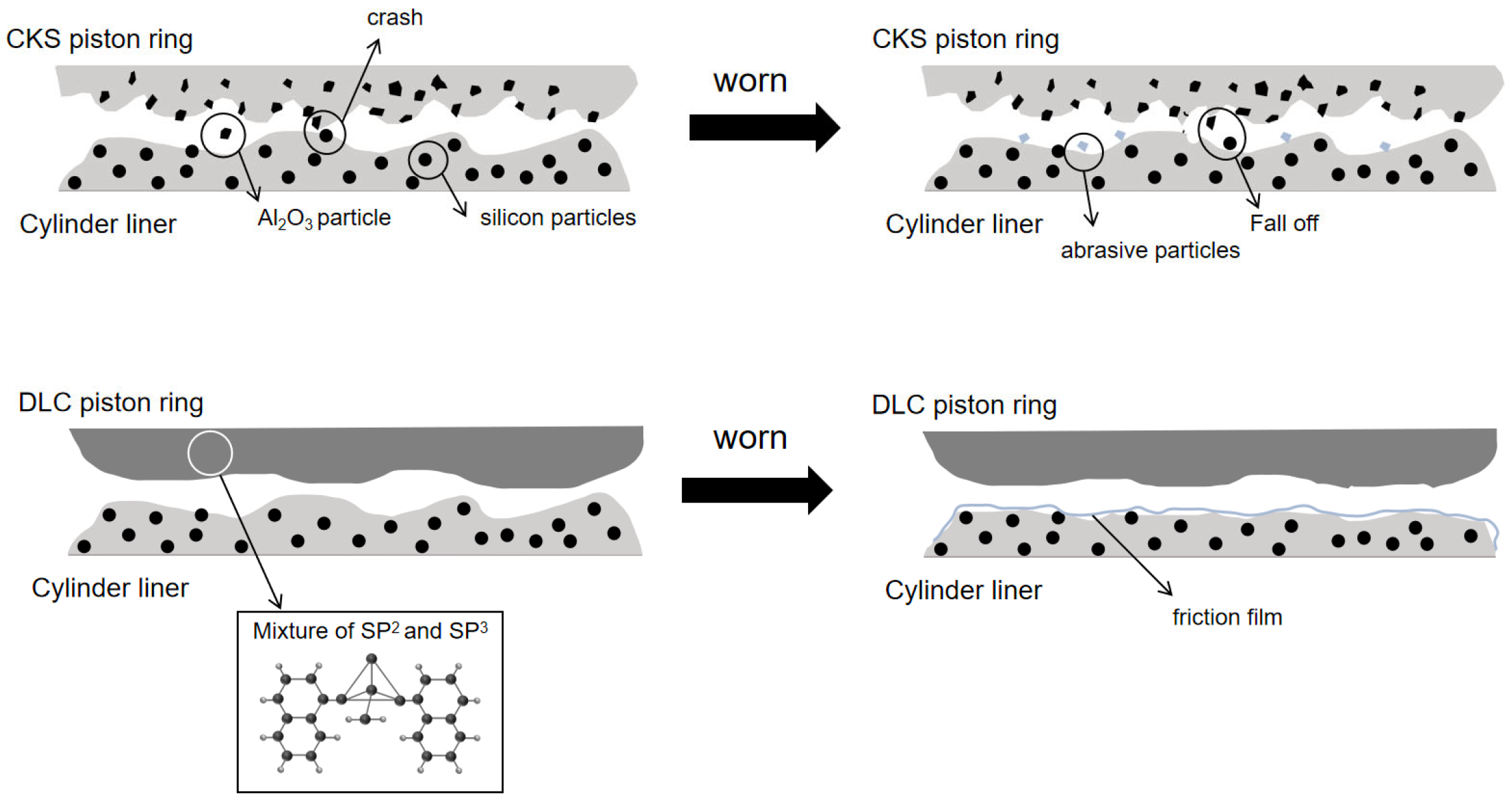
The wear mechanisms of the cylinder liner paired with the CKS and DLC piston rings are shown in Figure 13, as derived from the experiments. The cylinder liner contains uniformly distributed fine silicon particles. When the piston ring coating paired with the aluminum–silicon alloy cylinder liner is chromium-based ceramic composite plating (CKS), fine ceramic particles can be seen on the polished surface of the CKS piston ring before the test. These particles are embedded in the crevices of the chromium-based plating. During the wear process, these particles collide with the silicon particles in the cylinder liner, causing the silicon particles to detach and form abrasive particles. This leads to abrasive wear, exacerbating the wear of both the piston ring and cylinder liner. As a result, the original transverse machining marks on the piston ring surface were removed, and plowing marks along the sliding direction, as well as particle detachment traces, are observed on the cylinder liner surface.
DLC piston rings are coated with diamond-like coatings, which are wear-resistant coatings composed primarily of carbon elements. This coating has a dense structure without blocky particles. Carbon atoms can bond in three ways at room temperature: sp1, sp2, and sp3. Pure graphite crystals are formed by sp2 bonds, while pure diamond is formed by sp3 bonds. The amorphous structure of DLC coatings combines the characteristics of graphite (sp2 hybridization) and diamond (sp3 hybridization), with their properties closely correlated to the sp2/sp3 ratio. Specifically, the proportion of sp3-hybridized carbon is a critical factor determining the coating’s hardness and wear resistance, with a higher ratio enhancing these mechanical properties. Conversely, a higher fraction of sp2-hybridized carbon tends to impart lubricity to the coating. This unique structural feature enables DLC coatings to simultaneously achieve high hardness and a low friction coefficient, making them particularly suitable for components such as piston rings that demand both wear resistance and friction reduction. When the sp3 content is elevated, the coating’s enhanced hardness significantly improves its anti-wear performance. Combined with the graphitization mechanism related to sp2 hybridization concurrently (i.e., the formation of a carbon transfer layer), this can further optimize the tribological performance of the piston ring and cylinder liner friction pair [15]. In DLC coatings, sp2 bonding forms a hexagonal planar network structure with covalent bonds between carbon atoms, while van der Waals forces act between the layers, helping to reduce the friction coefficient. In contrast, sp3 bonding forms a tetrahedral structure with each carbon atom covalently bonded to four neighboring carbon atoms, increasing the surface hardness of the piston ring [17,18,19]. The hardness of the DLC coating is 2.42 times higher than that of the chromium-based ceramic composite coating (CKS piston ring). When paired with the cylinder liner, the high hardness and lubrication properties of the DLC coating result in lower friction forces and coefficients compared to the CKS piston ring, as well as reduced wear volumes. For the CKS piston ring–Al-Si cylinder liner pair, debonded silicon particles from the cylinder liner interact with Cr-based ceramic particles embedded in the CKS coating; collisions between these particles cause mutual breakage, generating mixed abrasive debris (silicon oxides and chromium oxides) that induce severe plowing wear, as evidenced by the deep scratches and particle detachment pits on the worn surfaces (Figure 11a and Figure 12a). After wear, the DLC coating surface retains some of the original machining marks, remains smooth, and exhibits minimal wear. For the DLC piston ring–Al-Si cylinder liner pair, the sp2-hybridized carbon in DLC coatings reacts with oxygen in the environment during reciprocating sliding, forming a thin and continuous tribofilm on the friction interface. This tribofilm, mainly composed of C-O and C-P chemical bonds, acts as a lubricating barrier to reduce direct contact between the DLC coating and Al-Si cylinder liner, which is consistent with the smooth worn surface and minimal wear observed in Figure 11b and Figure 12b. This tribofilm formation mechanism further explains the superior tribological performance of the DLC pairing. Although silicon particles detach from the cylinder liner surface, the wear volume is small. In contrast, when paired with the CKS piston ring, the cylinder liner surface experiences severe wear, with abrasive wear and significant wear volumes.
In conclusion, the aluminum–silicon alloy cylinder liner paired with the DLC piston ring exhibits superior tribological properties, making it suitable for the actual operating conditions of cylinder liner and piston ring pairs in internal combustion engines.

4. Conclusions

The wear performance of aluminum–silicon alloy cylinder liners paired with CKS and DLC piston rings is presented in this paper. A series of experiments were conducted using an aluminum–silicon alloy cylinder liner with a CKS piston ring and a DLC piston ring. An opposed reciprocating tribometer was utilized to simulate the actual operating conditions of the pairs. Through material characterization, friction and wear tests, and mechanism analysis, the performance differences and underlying mechanisms of different friction pairs were systematically elucidated. The key findings are summarized as follows:
(1)
When the aluminum–silicon alloy cylinder liner is paired with the DLC piston ring, compared to pairing with the CKS piston ring, the friction coefficient is reduced by 27.82%, the wear volume of the cylinder liner is reduced by 83.52%, and the ear volume of the piston ring is reduced by 97.5%. This pairing exhibits lower friction coefficients and wear volumes, demonstrating superior tribological properties.
(2)
When the aluminum–silicon alloy cylinder liner is paired with the CKS piston ring, distinct plowing marks are observed on the surface of the CKS piston ring after wear. Additionally, pits caused by the detachment of silicon particles are evident on the cylinder liner surface, indicating abrasive wear during the interaction between the cylinder liner and piston ring. In contrast, the surface of the DLC piston ring after wear remains relatively smooth, with minimal wear and retention of the original machining marks. Although scratches along the sliding direction are observed on the cylinder liner, the wear surface is smooth, and no abrasive wear is present.
(3)
The CKS piston ring coating, with fine ceramic particles in a chromium matrix, and the cylinder liner, containing uniformly distributed fine silicon particles, undergo particle detachment during wear. This generates abrasives that exacerbate frictional wear of the pair (higher friction coefficient, abrasive wear), leading to plowing marks on the CKS ring and particle detachment pits on the liner. In contrast, the DLC coating—with sp3-and sp2-hybridized carbon, combining diamond’s hardness and graphite’s lubricity—when paired with the Al-Si liner, exhibits a smooth surface without abrasive wear, as well as significantly lower friction and wear, thus showing superior performance.

Author Contributions

Writing—original draft, Y.G.; writing—review and editing, C.-D.L.; investigation, X.C.; data curation, S.-X.Z.; resources, L.-J.D.; methodology, P.Y.; software, X.-F.D., L.-B.Z. and L.-Y.W. All authors have read and agreed to the published version of the manuscript.

Funding

This paper was financially supported by the Natural Science Foundation of Jiangxi (20232BAB204105, 20224BAB214041).

Data Availability Statement

The original contributions presented in this study are included in the article. Further inquiries can be directed to the corresponding author.

Conflicts of Interest

The authors declare no conflict of interest.

References

  1. Markut, T.; Summer, F.; Pusterhofer, M.; Grün, F. Emergence of Coated Piston Ring Scuffing Behavior on an Application-Oriented Tribological Model Test System. Lubricants 2024, 12, 218. [Google Scholar] [CrossRef]
  2. Wong, V.W.; Tung, S.C. Overview of automotive engine friction and reduction trends–Effects of surface, material, and lubricant-additive technologies. Friction 2016, 4, 1–28. [Google Scholar] [CrossRef]
  3. Slattery, B.; Edrisy, A.; Perry, T. Investigation of wear induced surface and subsurface deformation in a linerless Al–Si engine. Wear 2010, 269, 298–309. [Google Scholar] [CrossRef]
  4. Li, C.; Chen, X.; Liu, H.; Dong, L.; Jian, H.; Wang, J.; Du, F. Tribological Performance and Scuffing Resistance of Cast-Iron Cylinder Liners and aluminum-silicon alloy cylinder liners. Coatings 2023, 13, 1951. [Google Scholar] [CrossRef]
  5. Li, C.D.; Chen, X.; Du, F.-M.; Shen, Y.; Xu, J.-J. The influence of protruding silicon particle shape on the friction performance of Al–Si alloy. Surf. Topogr. Metrol. Prop. 2020, 8, 025022. [Google Scholar] [CrossRef]
  6. Esser, J.; Linde, R.; Münchow, F. Diamantbewehrte Laufschicht für Kompressionsringe. MTZ-Mot. Z. 2004, 65, 582–585. [Google Scholar] [CrossRef]
  7. Kennedy, M.; Hoppe, S.; Esser, J. Piston ring coating reduces gasoline engine friction. MTZ Worldw. 2012, 73, 40–43. [Google Scholar] [CrossRef]
  8. Ma, S.; Chen, W.; Li, C.; Jin, M.; Huang, R.-X.; Xu, J.-J. Wear properties and scuffing resistance of the Cr–Al2O3 coated piston rings: The effect of convexity position on barrel surface. J. Tribol. 2019, 141, 021301. [Google Scholar] [CrossRef]
  9. Ohtake, N.; Hiratsuka, M.; Kanda, K.; Akasaka, H.; Tsujioka, M.; Hirakuri, K.; Hirata, A.; Ohana, T.; Inaba, H.; Kano, M.; et al. Properties and classification of diamond-like carbon films. Materials 2021, 14, 315. [Google Scholar] [CrossRef] [PubMed]
  10. Tyagi, A.; Walia, R.; Murtaza, Q.; Pandey, S.M.; Tyagi, P.K.; Bajaj, B. A critical review of diamond like carbon coating for wear resistance applications. Int. J. Refract. Met. Hard Mater. 2019, 78, 107–122. [Google Scholar] [CrossRef]
  11. Rajak, D.K.; Kumar, A.; Behera, A.; Menezes, P.L. Diamond-like carbon (DLC) coatings: Classification, properties, and applications. Appl. Sci. 2021, 11, 4445. [Google Scholar] [CrossRef]
  12. Moriguchi, H.; Ohara, H.; Tsujioka, M. History and applications of diamond-like carbon manufacturing processes. Sei Tech. Rev. 2016, 82, 52–58. [Google Scholar]
  13. Wan, S.H.; Li, D.S.; Zhang, G.A.; Tieu, A.K.; Zhang, B. Comparison of the scuffing behaviour and wear resistance of candidate engineered coatings for automotive piston rings. Tribol. Int. 2017, 106, 10–22. [Google Scholar] [CrossRef]
  14. Wang, Y.; Sun, Z.; Huang, R.; Zhao, Z.; Zhang, W. Tribological Properties of Several Surface-Modified Piston Rings Under Extreme Conditions. ASME J. Tribol. 2024, 146, 011701. [Google Scholar] [CrossRef]
  15. Ferreira, R.; Almeida, R.; Carvalho, Ó.; Sobral, L.; Carvalho, S.; Silva, F. Influence of a DLC coating topography in the piston ring/cylinder liner tribological performance. J. Manuf. Process. 2021, 66, 483–493. [Google Scholar] [CrossRef]
  16. Bian, X.; Han, X.; Luo, J.; Li, C.; Hao, M. Effect of composite surface treatments on wear performance of Al-Si alloy cylinder liner. Ind. Lubr. Tribol. 2023, 75, 858–865. [Google Scholar] [CrossRef]
  17. Mabuchi, Y.; Higuchi, T.; Weihnacht, V. Effect of sp2/sp3 bonding ratio and nitrogen content on friction properties of hydrogen-free DLC coatings. Tribol. Int. 2013, 62, 130–140. [Google Scholar] [CrossRef]
  18. Kennedy, M.; Hoppe, S.; Esser, J. Lower friction losses with new piston ring coating. MTZ Worldw. 2014, 3, 30–35. [Google Scholar] [CrossRef]
  19. Dearnaley, G.; Arps, J.H. Biomedical applications of diamond-like carbon (DLC) coatings: A review. Surf. Coat. Technol. 2005, 200, 2518–2524. [Google Scholar] [CrossRef]
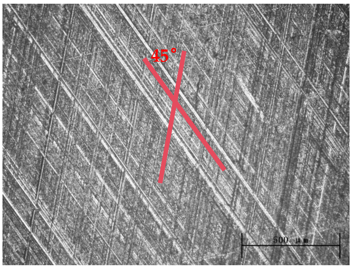
Figure 1. Honing pattern on the surface of cylinder liner.
Lubricants 13 00487 g001
Figure 2. Matrix structure of aluminum–silicon alloy cylinder liner. (a) Polished surface. (b) Magnified view of the polished surface.
Lubricants 13 00487 g002
Figure 3. Surface morphology of piston rings. (a) The surface topography of the CKS ring; (b) the surface topography of the DLC ring; (c) the polished surface morphology of the CKS ring; and (d) the polished surface morphology of the DLC ring.
Lubricants 13 00487 g003aLubricants 13 00487 g003b
Figure 4. Matrix structures of the piston rings. (a) CKS piston ring and (b) DLC piston ring.
Lubricants 13 00487 g004
Figure 5. The bonding states between the coating morphology and the substrates of the piston rings. (a) Cross-sectional morphology of CKS piston ring coating, (b) cross-sectional morphology of DLC piston ring coating, (c) bonding state between coating and substrate of CKS piston, and (d) bonding state between coating and substrate of DLC piston ring.
Lubricants 13 00487 g005aLubricants 13 00487 g005b
Figure 6. Wear testing machine for cylinder liner–piston ring specimens.
Lubricants 13 00487 g006
Figure 7. Curve of friction force changing with time.
Lubricants 13 00487 g007
Figure 8. Graph of the trend of friction force changing with time. (a) Aluminum–silicon alloy cylinder liner–DLC ring and (b) aluminum–silicon alloy cylinder liner–CKS ring.
Lubricants 13 00487 g008
Figure 9. Friction coefficients of two paired pairs.
Lubricants 13 00487 g009
Figure 10. Wear volumes of two sets of paired pairs. (a) Wear volume of cylinder liner, (b) Wear volume of piston ring.
Lubricants 13 00487 g010
Figure 11. The worn surface morphology of the cylinder liner. (a) Aluminum–silicon alloy cylinder liner–CKS ring, (b) aluminum–silicon alloy cylinder liner–DLC ring.
Lubricants 13 00487 g011
Figure 12. The worn surface of the piston ring. (a) SEM morphology of CKS ring, (b) SEM morphology of DLC ring, (c) EDX of CKS ring, and (d) EDX of DLC ring.
Lubricants 13 00487 g012
Figure 13. The wear mechanism.
Lubricants 13 00487 g013
Table 1. Elemental composition of Al-Si alloy cylinder liner.
ElementSiFeNiCuMnMgVAl
Mass Fraction20%5%2%3%2%1%<1%balanced
Table 2. Hardness measurement results of aluminum–silicon alloy cylinder liner.
Experimental Order12345Average
Microhardness (HV0.3)441.2430.0450.6426.2391.2428.0
Disclaimer/Publisher’s Note: The statements, opinions and data contained in all publications are solely those of the individual author(s) and contributor(s) and not of MDPI and/or the editor(s). MDPI and/or the editor(s) disclaim responsibility for any injury to people or property resulting from any ideas, methods, instructions or products referred to in the content.