Abstract
This study investigates the flow field and temperature field characteristics of a certain type of aerospace tail-thrust clutch friction plate under engagement conditions. A thermo–fluid–solid coupled convective heat transfer model was established based on the velocity distribution of lubricating oil within the groove cavities. The model was applied to analyze the surface temperature distribution of a single friction pair (friction plate and steel plate) under different operating parameters. The results reveal that both the inlet temperature and flow rate of the lubricating oil have a mitigating effect on temperature rise. However, due to the geometric constraints of the groove structure, the maximum wetted area and the actual inflow are inherently limited. Consequently, the temperature evolution during engagement is more significantly influenced by rotational speed and applied pressure. In particular, once these parameters exceed certain critical values, the surface temperature exhibits a sharp increase. Furthermore, the optimization of lubricating flow is constrained by friction materials. A higher flow rate does not necessarily yield greater lubrication benefits; instead, the optimal flow rate solution tailored to the friction pair should be pursued. This work provides theoretical insights into parameter control for aerospace tail-thrust clutches in practical operation.
1. Introduction
Currently, tail push helicopters are capable of both vertical take-off and high-speed forward flight [1,2]. This performance is achieved through the smooth power transmission enabled by friction clutches, which have become a critical component in high-power aeronautical actively controlled pusher propulsion systems due to their ability to transmit high power levels at elevated rotational speeds [3]. Power is transmitted between the input and output shafts via multiple friction pairs consisting of steel separator plates and friction discs. During operation, the clutch transmits torque through frictional contact, and the relative sliding between the driving and driven sides of these pairs generates substantial heat, which is absorbed by the friction materials. If this heat is not effectively removed by the cooling system, it can lead to excessive temperatures and thermal stresses in the steel plates and friction discs, potentially causing thermal distortion and warping of the steel separators. Therefore, enhancing the lubrication performance of the friction pairs and accurately simulating their thermal behavior under various operating conditions—as well as the heat transfer capability between the lubricating oil and the friction interfaces through thermo–fluid–structural coupling analysis—are of significant importance [4].
In the field of thermal behavior research on friction clutches, a number of scholars have conducted systematic investigations. Abdullah et al. [5] developed a program for calculating the frictional heat generation and its distribution in the contact areas of clutch system components during the sliding phase. Huang, Z. et al. [6] derived computational methods for convective heat transfer on both the annular surface and the contact interface of friction pairs with rectangular grooves and concentric circular grooves. Jin et al. [7] analyzed the evolution of the temperature field during dynamic heat flux partitioning using a solid–liquid convective heat transfer model based on the flow field distribution of the lubricating oil. Yu et al. [8] investigated the influence of the transition from uniform contact state (UCS) to intermittent contact state (ICS) on the thermodynamic characteristics of friction pairs. Liu et al. [9] established a two-dimensional transient temperature field simulation model for friction plates and proposed a numerical solution for surface temperature distribution at different radii based on the finite difference method. Compared with traditional prediction approaches, this method achieved higher accuracy. Furthermore, the effects of pressure and relative velocity on the surface temperature field were analyzed, revealing that the surface temperature increases with both pressure and rotational speed during sliding contact. Kong et al. [10] examined the effect of lubricant convection on temperature distribution, demonstrating that radially arranged arc-shaped grooves promote favorable flow patterns during the rotation of wet friction discs, thereby enhancing convective lubricant flow.
Regarding the simulation research of friction plates, Tan et al. [11] investigated a high-speed helicopter wet friction clutch and developed a thermo–fluid–solid coupling simulation model based on radial and annular composite grooves. The model revealed the flow characteristics and temperature distribution of the lubricating oil within the groove channels of the friction disk. Using the Taguchi experimental design and a multi-objective optimization algorithm, they achieved a coordinated optimization of drag torque and overall temperature rise. Similarly, Zhang et al. [12] established a multiphysical-field co-simulation model considering the groove structure on the friction plate surface, focusing on the effects of groove inclination, groove number, and groove depth on the thermal load characteristics of the steel plate. Zheng et al. [13] developed a numerical model to obtain the temperature rise characteristics of a wet multi-disc clutch under different separation clearances during continuous shifting, which was experimentally validated on an SAE #2 test bench. Saffa et al. [14] investigated the thermoelastic behavior of a single-disc friction system during the sliding period using the finite element method. Based on axisymmetric finite element simulations, it was found that under a constant frictional heat flux, the sliding speed has a more pronounced influence on temperature rise than the applied pressure. Jin et al. [15] studied the torque generation mechanism during the sliding process of wet clutches by establishing an improved torque calculation model validated through multiple experimental conditions. Their results indicated that, according to the fluid–structure interaction analysis, the effects of applied pressure, relative speed, and oil flow rate on torque decrease successively. A microscopic analysis further revealed the intrinsic mechanism governing torque variation under different operating conditions. Wu et al. [16] constructed a single-pair rough contact model and proposed two characterization parameters for temperature-field-induced failure. The model was coupled in real time with a macroscopic thermo-mechanical simulation model. By applying a control variable method, the effects of pressure and speed on the failure parameters were examined, indicating that the failure parameters are more sensitive to variations in pressure.
Most of the above studies have primarily focused on the microscopic mechanisms of torque generation and local flow-field optimization in wet clutches, providing valuable insights into the underlying physical processes, while also examining the variations in transmitted torque under different conditions [17,18]. In this work, a steady-state Multiple Reference Frame (MRF) approach is employed to develop an efficient thermal simulation model based on the engineering requirements of an aerospace helicopter tail-thrust clutch operating under variable rotational speed conditions. The effects of multiple operating parameters—including engagement pressure, inlet flow rate, rotational speed, and oil inlet temperature—on the overall temperature distribution of the friction pair are systematically analyzed. The results aim to provide direct and practical data support for thermal design and operating condition planning in real engineering applications.
2. Theoretical Method
2.1. Thermo–Fluid–Solid Coupling Method
In general, thermo–fluid–solid coupling (TFSC) is a complex problem, and in the strict sense, it represents a multiphysics coupling phenomenon [19,20,21,22]. For clutch friction pairs, the interaction involves frictional heat generation between the friction plate and its mating steel plate (solid–solid frictional heating), heat transfer among the lubricating oil, friction plate, and steel plate (fluid–solid heat transfer), as well as thermal deformation within the friction plate and steel plate (solid stress field). The corresponding relationships are illustrated in Figure 1.
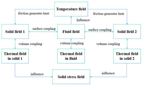
Figure 1.
Multiphysics coupling schematic.
Assuming the lubricating oil to be an incompressible Newtonian fluid, the governing equations can be formulated by combining the conservation laws of mass, momentum, and energy in the fluid domain with thermoelastic deformation in the solid domain [23]. The fluid behavior is governed by the Navier–Stokes equations, which incorporate the continuity equation (mass conservation) and the momentum conservation equation. The energy equation is solved to account for heat transfer within the fluid. On the solid boundary, Fourier’s law describes conductive heat transfer, while thermal expansion of the structure is coupled with temperature-dependent material properties through the generalized Hooke’s law. Interface conditions ensure continuity of temperature, heat flux, and stress, thereby achieving bidirectional coupling: fluid-induced shear stress and convective heat transfer alter the structural temperature field, while the resulting deformation modifies the flow distribution and heat transfer. This nonlinear feedback loop governs the overall stability and thermal performance of the system. Therefore, accurate thermo–fluid–solid coupling (TFSC) analysis requires simultaneous resolution of the fluid, thermal, and solid fields within a unified framework, rather than treating them in isolation.
Specifically, in the fluid domain, the governing equations consist of the incompressible Navier–Stokes equations and the energy equation [24]:
where is the velocity vector, is the pressure, is the temperature, is the fluid density, is the dynamic viscosity, is the specific heat at constant pressure, is the thermal conductivity of the fluid, and denotes the viscous dissipation term.
In the solid region, heat conduction and thermoelastic deformation are considered:
where , and are the density, specific heat, and thermal conductivity of the solid, respectively. is the stress tensor, is the strain tensor, is the coefficient of thermal expansion, and denotes the elastic stiffness tensor.
At the fluid–solid interface, continuity of velocity, stress, temperature, and heat flux must be satisfied:
This set of governing equations and coupling conditions provides the theoretical framework for analyzing the bidirectional interaction among thermal, fluid, and structural fields in the system.
2.2. Heat Flux Calculation
During the engagement of a wet friction clutch, the steel plate and friction plate are compressed by the pressure exerted by the piston. The relative rotational speed difference between the two surfaces generates a frictional torque, which drives the input shaft and output shaft to rotate together. At the same time, this frictional torque produces frictional work, leading to heat generation [10,25]. In the present calculation, it is likewise assumed that the contact pressure between the friction pairs is uniformly distributed [26]. Considering that the tangential velocity of the friction pair varies with radius, the resulting frictional torque also differs across radii, which in turn affects the distribution of heat flux density on both the steel plate and friction plate. For computational convenience, the friction pair contact region can be discretized along the radial direction into infinitesimal elements as illustrated in Figure 2.
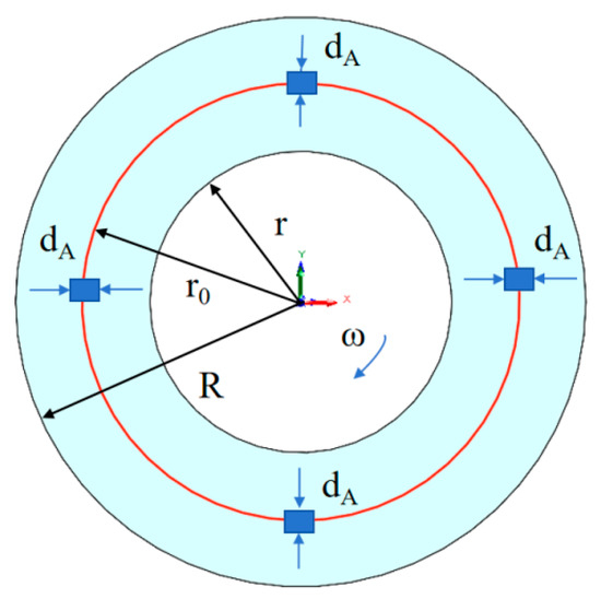
Figure 2.
Friction Micro-Element Schematic.
Based on the aforementioned conditions, the frictional work on the annular element at radius r of the friction pair can be approximately calculated as:
where is the normal engagement pressure between the friction pairs, and are the outer and inner radii of the friction pair, is the infinitesimal area of the friction pair element (), is the coefficient of friction, and is the relative angular velocity.
The behavior of the sliding angular speed with time can be written as [20]:
where is the initial angular sliding speed. is the total time required to complete the combination.
According to Equations (8) and (9), on the circular ring of the friction pair, the heat flux at radius can be expressed as [12,27,28]:
3. Numerical Model
3.1. Geometric Model
In aerospace clutches, due to the requirement of transmitting high power and ensuring reliable engagement, a multi-disc configuration combining multiple friction plates with mating steel plates is commonly employed. This coupling arrangement is complex and exhibits axial symmetry. To focus on the influence of operating parameters on a single friction pair, the present study selects one friction pair for analysis. A commonly used radial composite groove pattern in aerospace applications is adopted, and the investigation is carried out under its maximum operating parameters. The constructed model consists of one friction plate and two mating steel plates, forming a complete friction pair. The geometric configuration is shown in Figure 3, and the dimensional parameters are listed in Table 1.
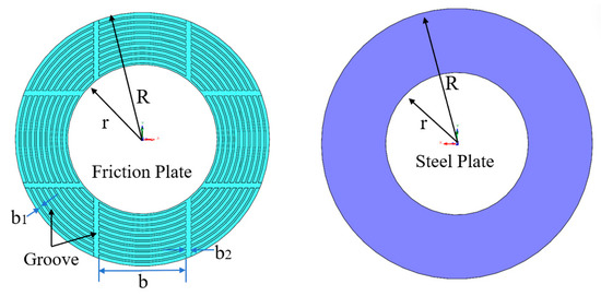
Figure 3.
Geometric model of the friction disc and separator plate.

Table 1.
Geometric parameters of the friction pair.
3.2. Material Properties
The material property parameters are listed in Table 2. The separator plate is made of heat-treated alloy steel. The friction disc consists of two types of sintered composite materials: the outer layer is composed of high-temperature-resistant paper-based material, and the base plate is also made of high-temperature-resistant alloy steel.
Table 2.
Material property parameters.
The material properties of the lubricating oil are provided in Table 3. AeroShell Turbine Engine Oil 555 was used as the lubricant in this study.
Table 3.
Material parameters of the oil.
The simulation model is illustrated in Figure 4. The computational domain was discretized using unstructured grids generated with Fluent Meshing software. To balance computational accuracy and efficiency, global size controls were first applied to the entire model. Local refinement was implemented specifically on the groove surfaces to capture critical flow details. Five layers of inflation meshes were generated at the fluid–solid interfaces. A low-y+ resolution strategy was applied in the near-wall region, achieving a target value of on all wall surfaces with enhanced wall treatment. The boundary layer consisted of five layers with a growth rate of 1.15, ensuring adequate resolution of velocity and temperature gradients within the boundary layer and meeting the requirements of conjugate heat-transfer analysis. Further improving mesh quality, cells with a mesh quality below 0.2 were remeshed, including both surface and volume grids. The final mesh contained 2,657,816 elements, with skewness values below 0.7 and orthogonal quality above 0.2, satisfying the basic quality criteria required for CFD simulations.
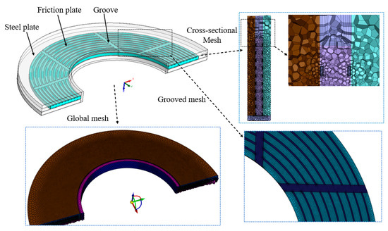
Figure 4.
Finite Element Model of the Friction Pair.
3.3. Boundary Conditions
During clutch engagement, the piston actuates the axial movement of a steel plate toward the friction surface, generating a normal engagement pressure. Torque is subsequently produced by the resulting friction force, which drives the output shaft into motion. As the input shaft rotates at high speed, the output shaft undergoes a rapid change in rotational velocity during the engagement period until it synchronizes with the input speed [28,29]. A schematic diagram of this engagement process is provided in Figure 5.
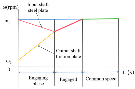
Figure 5.
Engagement Process of the Friction Pair.
As shown in Figure 6, the friction plate and the mating steel plate are assigned different materials. In the calculation process, the effect of gravity can be neglected, since the centrifugal acceleration generated by high-speed rotation is dominant [16]. The inlet boundary condition is specified as a mass flow inlet, while the outlet is defined as a pressure outlet. The oil layer surface is set as an interface coupled with the solid domain. Heat transfer within the friction pair is modeled as forced convection, with thermal exchange among the friction plate, steel plate, and lubricating oil determined by their material properties and convective parameters. At the coupling interface of the friction plate, a heat source is applied via a user-defined function (UDF), based on Equation (10). The heat source is defined as a function of working pressure, speed difference, radius of the friction pair, and time. To evaluate the effect of each operating parameter on the temperature field, the single-variable method was applied, where the friction coefficient and time were kept constant. The friction coefficient was set to 0.12, a typical value for paper-based friction materials, and the time was chosen at the moment of maximum relative speed difference—that is, when the friction pair first comes into contact and the heat generation reaches its peak. This heat source is formulated as a function of working pressure, relative rotational speed, and radius. A single-factor analysis was conducted to examine the effects of engagement pressure and speed difference on the temperature field of the friction pair. The heat source was applied to the contact surface between the friction plate and steel plate, with the heat flux distribution ratio automatically determined according to the material properties of each component.
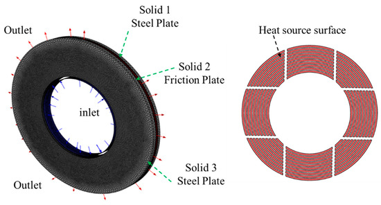
Figure 6.
Friction Pair Boundary Conditions.
To simulate the influence of different relative rotational speeds on the temperature field of the friction pair, the Multiple Reference Frame (MRF) model was employed for the calculation of both the flow field and the temperature field. Since this is a pseudo-transient calculation, it offers relatively high computational efficiency and good numerical stability, making it possible to quickly assess the influence of operating parameters on the friction pair. This model offers significant advantages in handling problems involving multiple rotating regions. In the simulation setup, the rotational speeds of the input shaft and the separator plates were held constant, while the output shaft and the lubricating oil were set to rotate at specified speeds, thereby modeling the oil-throwing lubrication mechanism from the central shaft of the friction pair. The temperature distribution was analyzed under various conditions of relative speed difference, engagement pressure, inlet flow rate, and inlet oil temperature.
3.4. Turbulence Model
The Reynolds number quantitatively describes the ratio of inertial to viscous forces in a fluid and serves as a fundamental criterion for determining the flow regime. When the Reynolds number is low, viscous forces dominate and the flow remains laminar, for which a laminar model should be applied. At high Reynolds numbers, inertial forces prevail, and the flow transitions to turbulence, requiring the adoption of a turbulence model. For rotating machinery, the Reynolds number is typically calculated as:
where is the fluid density, is the angular velocity, is the characteristic radius, and is the dynamic viscosity.
In the present aerospace friction clutch, the rotational speed reaches 4800 rpm, resulting in a Reynolds number of approximately 2.68 × 10⁵. Generally, for external flows, turbulence occurs when Re > 5 × 10⁵, while for internal flows, turbulence is typically established when Re > 2300. Therefore, the present case clearly corresponds to a highly turbulent flow regime.
Commonly used turbulence models for fluid flow analysis include several categories. The Spalart–Allmaras (S–A) one-equation model offers low computational cost and performs well in aerospace external flow simulations; however, its applicability is limited for complex internal flows and strong separation regions. The standard model and its variants, such as RNG and Realizable , are robust and computationally efficient for high-Reynolds-number, fully developed turbulence. Nevertheless, their accuracy decreases in flows with strong streamline curvature, rotation, or adverse pressure gradients, which often lead to flow separation. Among the family, the Shear Stress Transport (SST) model is the most representative. This model effectively combines the advantages of both the and formulations. Near the wall, it uses the model, allowing integration down to the viscous sublayer without wall-function corrections (suitable for fine grids with ), enabling accurate predictions of wall friction and heat transfer. In the free-stream region, it transitions smoothly to a -like behavior, thereby reducing sensitivity to the inlet turbulence properties. Importantly, the SST model incorporates a shear stress transport limiter that enhances prediction accuracy under adverse pressure gradients, especially in capturing the onset and extent of flow separation.
Therefore, considering the high-intensity turbulence (Re ≈ 2.68 × 10⁵) and strong rotational effects in this study, the SST turbulence model with curvature correction was adopted to accurately capture the complex turbulent flow behavior within the friction clutch.
4. Results and Discussion
4.1. Flow Field Distribution at Different Rotational Speeds
Figure 7 illustrates the flow field distribution under different rotational speeds. It can be observed that the flow field is significantly influenced by centrifugal force. The flow velocity along the groove surfaces increases radially outward. The majority of the lubricating oil flows through the vertical grooves, where the velocity is considerably higher than that in the annular regions. This trend becomes more pronounced as the rotational speed increases, indicating effective lubricant throughput in this groove design. However, the limited oil flow in the annular grooves may lead to localized high-temperature phenomena.
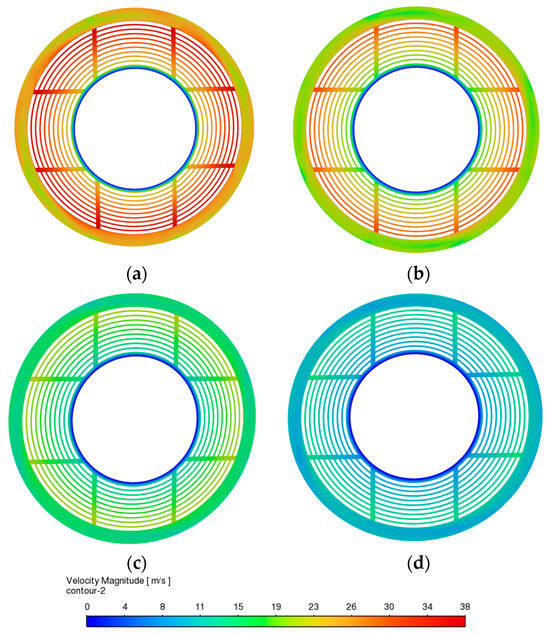
Figure 7.
Flow field distribution over the grooved surface at different rotational speeds: (a) = 4800 rpm; (b) = 4000 rpm; (c) = 3000 rpm; (d) = 2000 rpm.
Figure 8 shows the flow field distribution at the cross-section of the grooves under different rotational speeds. The velocity trend continues to increase radially outward. At the outlet, the flow velocity is significantly influenced by wall adhesion, resulting in higher velocities along the wall surfaces. This phenomenon is particularly noticeable at a low speed of 1000 rpm. As the rotational speed increases, the outlet flow velocity rises, and this wall-adhesion effect diminishes, being replaced by more intense flow field variations. These results indicate that the flow field undergoes more drastic changes under high rotational speeds.
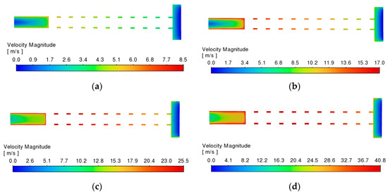
Figure 8.
Flow field distribution at the groove cross-section under different rotational speeds: (a) = 1000 rpm; (b) = 2000 rpm; (c) = 3000 rpm; (d) = 4800 rpm.
Figure 9 summarizes the maximum velocity of the lubricating oil on the groove plane and the average velocity at the outlet. As the rotational speed increases, the average outlet velocity increases gradually, while the maximum velocity shows a more significant rise. This indicates that, although increasing the rotational speed can enhance the flow velocity of the lubricating oil passing through the friction discs, the actual throughput is constrained by the structural parameters of the grooves. As a result, the rate of lubricant passage does not improve markedly with higher rotational speeds.
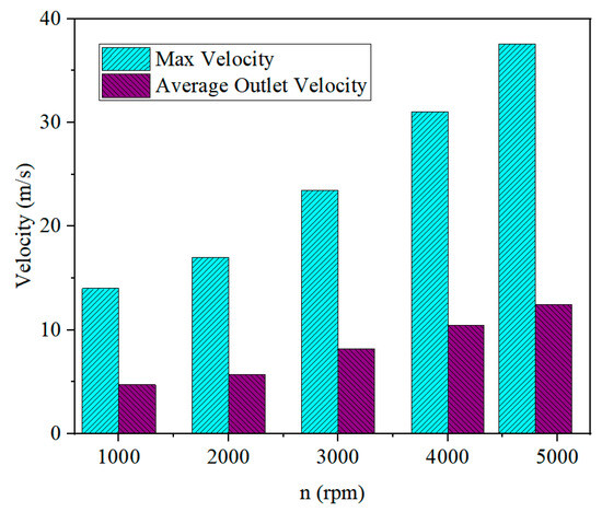
Figure 9.
Maximum and average velocities of lubricating oil.
4.2. Temperature Field Distribution Under Different Engagement Pressures and Inlet Oil Temperatures
Figure 10a presents the average and maximum temperatures of the friction plate and steel plate under different engagement pressures. The results indicate that the surface temperature increases nonlinearly with pressure, where the maximum temperature exhibits a more pronounced rise compared with the average temperature. Specifically, the maximum temperature increases from 125 °C to 270 °C, indicating that engagement pressure is a critical factor affecting the peak temperature. Figure 10b illustrates the variation in outlet temperature under different engagement pressures. With the overall temperature rise, the outlet temperature increases slightly. This suggests that the increase is mainly attributed to the elevated surface temperature at the contact interface, which in turn raises the outlet temperature, while also reflecting the inherent limitation of the heat exchange capacity.
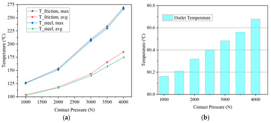
Figure 10.
(a) Average and maximum temperatures of the friction disc and the steel disc under different pressures. (b) Average temperature at the outlet under different pressures.
Figure 11a summarizes the average and maximum temperatures of the friction disc and the steel plate under different inlet oil temperatures. The inlet oil temperature significantly influences the surface temperature of the friction pair. When the inlet oil temperature is below 40 °C, the cooling effect is pronounced, whereas above 40 °C, the effect diminishes. Figure 11b shows the variation in outlet temperature under different inlet oil temperatures. It can be observed that the outlet temperature variation is significant below 40 °C, while it diminishes at higher temperatures. This indicates that increasing the temperature difference enhances heat exchange efficiency. However, as the inlet temperature rises, the heat exchange capacity gradually decreases.
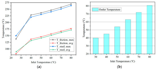
Figure 11.
(a) Average and maximum temperatures of the friction disc and the steel disc under different inlet oil temperatures. (b) Average temperature at the outlet under different inlet oil temperatures.
4.3. Distribution of the Temperature Field Under Different Rotational Speeds
To investigate the effect of centrifugal forces induced by rotational speed on the temperature distribution of friction plates and their mating steel plates, Figure 12 shows the temperature distribution of the friction plate and steel plate at rotational speeds of 0 and 1000 rpm, respectively, Under the 1000 rpm condition, a heat source term was applied to the contact surface between the friction plate and steel plate. Results indicate: without centrifugal force, lubricant primarily flows out through vertical grooves. Low-temperature zones in the friction pair concentrate near vertical grooves, while high-temperature zones cluster in the central region of annular grooves, reaching a maximum temperature of 232 °C. Comparing this with the temperature distribution at a rotational speed difference of 1000 rpm reveals that, under centrifugal force, the flow field undergoes significant changes. Both the circumferential and radial grooves receive lubrication, the high-temperature zone shrinks considerably, and the maximum temperature drops to 150 °C—a significant reduction. This demonstrates that centrifugal force produces a beneficial lubrication effect.
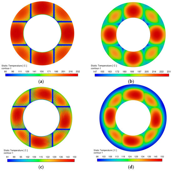
Figure 12.
Effect of Rotational Speed on the Temperature Field: (a) friction plate, n = 0 rpm; (b) steel plate, n = 0 rpm; (c) friction plate, n = 1000 rpm; (d) steel plate, n = 1000 rpm.
Subsequently, the engagement pressure of the friction pair was set to 4000 N, with the lubricant inlet temperature maintained at 80 °C and the inlet flow rate at 1.2 L/min, while the rotational speed was varied as the single independent variable. Figure 13 shows the average and maximum temperatures of the friction disc and the steel plate, as well as the average temperature at the outlet, under different rotational speeds. As rotational speed increases, the temperature of the friction plate and steel plate rises rapidly. When rotational speed reaches 4000 rpm, the temperature exhibits a sharp surge, indicating that rotational speed significantly impacts temperature, with a particularly pronounced effect on maximum temperature. Concurrently, the outlet temperature shows a slight increase, but the overall heat exchange rate remains low. This suggests that, while rotational speed influences heat transfer, it is also constrained by inlet temperature, limiting the heat exchange rate at the outlet.
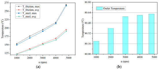
Figure 13.
(a) Average and maximum temperatures of the friction disc and the steel disc at different rotational speeds. (b) Average temperature at the outlet under different rotational speeds.
4.4. Temperature Field Distribution Under Different Inlet Flow Rates
In aerospace friction clutches, the flow rate of lubricant is a critical factor in controlling temperature rise. As other parameters—such as structural design, operating pressure, and rotational speed—are often difficult to adjust in real time during system operation, flow rate regulation provides a relatively flexible and effective means of managing heat accumulation through control of the cooling medium, thereby maintaining stable clutch operation within a suitable temperature range. In this study, the engagement pressure of the friction pair was set to 4000 N, the lubricant inlet temperature to 80 °C, and the rotational speed to 4800 rpm, with the flow rate varied as the single independent variable. Figure 14 shows the average and maximum temperatures of the friction disc under different flow rates. As the inlet flow rate increases, the temperature of the friction disc decreases; however, the distribution of high-temperature zones remains largely unchanged. Overall, the temperature rise is reduced with higher flow rates.
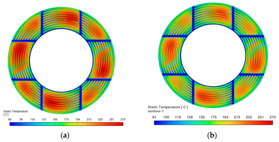
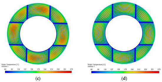
Figure 14.
Temperature field distribution of the friction disc under different inlet flow rates: (a) = 1.2 L/min; (b) = 2.4 L/min; (c) = 3.6 L/min; (d) = 4.8 L/min.
Figure 15 shows the average and maximum temperatures of the steel plate under different inlet flow rates. As the flow rate increases, the temperature of the steel plate decreases, accompanied by a reduction in the extent of high-temperature zones and an overall decline in temperature rise. Owing to the relatively high thermal conductivity of steel, heat exchange occurs more efficiently in the steel plate compared to the friction disc. Therefore, increasing the flow rate has a more pronounced cooling effect on the separator plate.
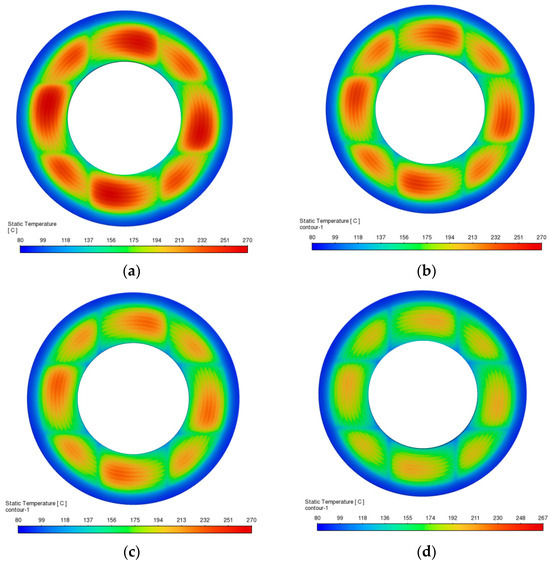
Figure 15.
Temperature field distribution of the steel plate under different inlet flow rates: (a) = 1.2 L/min; (b) = 2.4 L/min; (c) = 3.6 L/min; (d) = 4.8 L/min.
Figure 16 illustrates the temperature field distribution on the cross-section of the friction pair. The higher-temperature zones are primarily concentrated in the friction pair engagement area, with the steel plate exhibiting significantly higher temperatures compared to the paper-based friction material. Most heat dissipates through the steel plate, indicating that paper-based materials retain heat more readily. The steel plate rapidly transfers heat into the overall metal matrix and lubricating oil, resulting in a more uniform temperature distribution. As the flow rate increases, the overall temperature rise in the friction pair decreases, further demonstrating that increased lubricating oil is an effective cooling method.
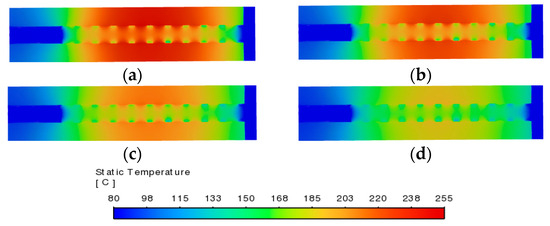
Figure 16.
Temperature field at the cross-section of the friction pair under different flow rates. (a) = 1.2 L/min; (b) = 2.4 L/min; (c) = 3.6 L/min; (d) = 4.8 L/min.
Figure 17 summarizes the temperature variations in the friction disc and the steel plate under different inlet flow rates. As flow rate increases from 1.2 L/min to 4.8 L/min, the temperature of the friction plate and steel plate decreases accordingly, with the maximum temperature showing a more pronounced drop than the average temperature. For this radial groove configuration, the most significant temperature reduction occurs when flow is maintained between 1.6 and 1.8 L/min. The outlet temperature variation remained relatively small. Overall, it was still influenced by the circumferential oil storage capacity of the groove design. Relying solely on vertical grooves to handle flow has a certain upper limit; hence, the temperature increased slightly.
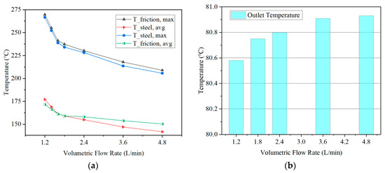
Figure 17.
(a) Average and maximum temperatures of the friction disc and the steel disc at different volumetric flow rates. (b) Average temperature at the outlet under different volumetric flow rates.
5. Conclusions
This study investigates the overheating issue in a wet friction clutch under high-speed and heavy-duty aerospace conditions. The thermal–fluid–solid coupling (TFSC) model was developed to analyze the flow and temperature fields of the friction pair under various operating parameters using a single-variable approach. The effects of engagement pressure, inlet oil temperature, rotational speed, and inlet flow rate were systematically examined. The main conclusions are as follows:
- Engagement pressure is a key factor inducing local thermal failure. An increase in engagement pressure significantly elevates the peak temperature of the friction pair, while its effect on the overall average temperature remains relatively limited. This indicates that high pressure tends to generate localized hot spots in the contact region, which are the primary cause of friction material ablation and thermal spot formation, particularly for paper-based materials.
- A lower inlet oil temperature is an effective means of controlling thermal rise. Reducing the inlet oil temperature can markedly enhance heat dissipation. In particular, when the inlet temperature is below 40 °C, its suppression effect on the overall temperature field becomes more pronounced. This provides a clear direction for developing early-stage cooling strategies in the system.
- Increasing rotational speed nonlinearly intensifies the system’s thermal load. The frictional heat generation power increases sharply with rotational speed, especially in the high-speed range. The resulting rapid temperature rise not only poses a risk of thermal runaway but also serves as a dominant factor leading to local burning or failure of the friction pair.
- Flow optimization exhibits a yield inflection point, with material thermal management capability being the key constraint. Increasing the lubricant flow rate is an effective method for temperature regulation, but its effectiveness is limited by the flow channel structure, exhibiting a distinct critical point of diminishing returns. Blindly increasing the flow rate is not an economically efficient choice; design should instead target identifying this inflection point. Additionally, paper-based friction linings exhibit poor thermal conductivity and high heat storage capacity. This results in higher operating temperatures under identical conditions, making them a key focus in system thermal design.
Author Contributions
Conceptualization, Y.D. and X.Z.; methodology, J.B., H.W. and X.Y.; software, J.B., G.Y. and X.Z.; validation, Y.D. and X.Z.; formal analysis, X.Z.; investigation, J.B., X.Y. and G.Y.; resources, Y.D.; data curation, H.W. and X.Y.; writing—original draft preparation, X.Z.; writing—review and editing, J.B., H.W. and X.Y.; visualization, G.Y.; supervision, X.Z. and Y.D.; project administration, Y.D.; funding acquisition, Y.D. All authors have read and agreed to the published version of the manuscript.
Funding
This work was supported by the Science and Technology Innovation Program of Hunan Province (Grant number 2024RC1001).
Data Availability Statement
The original contributions presented in the study are included in the article; further inquiries can be directed to the corresponding author.
Conflicts of Interest
The authors declare no conflicts of interest.
References
- Moodie, A.M.; Yeo, H. Design of a Cruise-Efficient Compound Helicopter. J. Am. Helicopter Soc. 2012, 57, 1–11. [Google Scholar] [CrossRef]
- Qiu, Y.; Li, Y.; Lang, J.; Wang, Z. Dynamics analysis and control of coaxial high-speed helicopter in transition flight. Aerosp. Sci. Technol. 2023, 137, 108278. [Google Scholar] [CrossRef]
- Xiao, Y.; Li, Q.; Liu, H. The Optimization and Control of the Engagement Pressure for a Helicopter Dry Clutch. Machines 2024, 12, 533. [Google Scholar] [CrossRef]
- Pointner-Gabriel, L.; Voelkel, K.; Stahl, K. Drag Losses of Wet Brakes and Clutches—A Scoping Review. Lubricants 2025, 13, 27. [Google Scholar] [CrossRef]
- Abdullah, O.I.; Schlattmann, J.; Majeed, M.H.; Sabri, L.A. The distribution of frictional heat generated between the contacting surfaces of the friction clutch system. Int. J. Interact. Des. Manuf. (IJIDeM) 2018, 13, 487–498. [Google Scholar] [CrossRef]
- Huang, Z.; Bao, H.; Xiao, Y.; Wei, Y. Transient thermal characteristic analysis and experimental validation of aviation wet friction clutch. J. Mech. Sci. Technol. 2025, 39, 2269–2283. [Google Scholar] [CrossRef]
- Jin, J.; Li, X.; Yang, S.; Sun, H.; Yi, H.; Hao, W. A temperature field model based on energy flow analysis of wet clutch sliding interface. Tribol. Int. 2024, 199, 109976. [Google Scholar] [CrossRef]
- Yu, L.; Zheng, C.; Wang, L.; Wu, J.; Jia, R. Influences of the Contact State between Friction Pairs on the Thermodynamic Characteristics of a Multi-Disc Clutch. Materials 2022, 15, 7758. [Google Scholar] [CrossRef]
- Liu, Y.; Sun, Y.; Gao, Z.; Ye, F.; Tang, P. Transient temperature characteristics of friction clutch disc considering thermal contact conductance under sliding conditions. Friction 2023, 11, 2253–2263. [Google Scholar] [CrossRef]
- Kong, J.; Jang, S. Temperature Analysis of Wet Clutch Surfaces During Clutch Engagement Processes Based on Friction Pad Patterns. Int. J. Automot. Technol. 2020, 21, 813–822. [Google Scholar] [CrossRef]
- Tan, W.; Chen, Z.; Li, Z.; Yan, H. Thermal-Fluid-Solid Coupling Simulation and Oil Groove Structure Optimization of Wet Friction Clutch for High-Speed Helicopter. Machines 2023, 11, 296. [Google Scholar] [CrossRef]
- Zhang, Z.; Mu, Z.; Yu, X. Mechanistic Study of Groove Parameters on the Thermoelastic Instability of Wet Clutch. Lubricants 2025, 13, 150. [Google Scholar] [CrossRef]
- Zheng, L.; Ma, B.; Chen, M.; Yu, L.; Wang, Q.; Xue, J. Study on the Temperature Rise Characteristics of Successive Clutch Shifting Considering the Disengaged Friction Pair Gaps. Machines 2022, 10, 576. [Google Scholar] [CrossRef]
- Saffar, I.Q.A.; Sultan, H.S.; Jweeg, M.J.; Abed, A.M.; Abdullah, O.I.; Schlattmann, J.; Sabri, L.A.; Alfilh, R.H.C. Investigation of the influence of sliding speed on thermoelastic problem in the frictional clutch system when applying a constant heat generation. Heat Transf. Res. 2023, 54, 19–40. [Google Scholar] [CrossRef]
- Jin, J.; Li, X.; Yang, S.; Yi, H.; Sun, H.; Hao, W. Calculation and analysis of wet clutch sliding torque based on fluid-solid coupling dynamic behavior. Tribol. Int. 2025, 202, 110363. [Google Scholar] [CrossRef]
- Wu, J.; Ding, A.; Yang, C.; Zhang, H.; Wang, L.; Li, H. Data-driven thermal safety threshold analysis of friction component based on macro-micro interaction model. Case Stud. Therm. Eng. 2025, 74, 106821. [Google Scholar] [CrossRef]
- Zhao, Q.; Ma, B.; Xiong, C.; Yu, L.; Fu, B.; Yan, S. Modeling of the Dynamics of Conical Separate Plates in a Wet Multi-Disc Clutch. Lubricants 2025, 13, 262. [Google Scholar] [CrossRef]
- Liang, X.; Chen, L.; Wang, Y.; Wan, L. A proposed torque calculation model for multi-plate clutch considering boundary lubrication conditions and heat transfer. Int. J. Heat Mass Transf. 2020, 157, 119732. [Google Scholar] [CrossRef]
- Gravemeier, V.; Civaner, S.M.; Wall, W.A. A partitioned-monolithic finite element method for thermo-fluid–structure interaction. Comput. Methods Appl. Mech. Eng. 2022, 401, 115596. [Google Scholar] [CrossRef]
- Abdullah, O.I.; Schlattmann, J.; Senatore, A.; Sabri, L.A.; Al-Sahb, W.S.A. Effect of Sliding Speed on the Thermal Stresses of Single-Disk Friction Clutches. J. Fail. Anal. Prev. 2020, 20, 1534–1540. [Google Scholar] [CrossRef]
- Wu, P.-h.; Zhou, X.; Yang, C.; Lv, H.; Lin, T.; Wu, X. Parametric analysis of the drag torque model of wet multi-plate friction clutch with groove consideration. Ind. Lubr. Tribol. 2018, 70, 1268–1281. [Google Scholar] [CrossRef]
- Abdullah, O.I.; Schlattmann, J.; Senatore, A.; Al-Shabibi, A.M. Investigation of thermoelastic problem of multiple-disc friction clutches applying different thermal loads. Heat Mass Transf. 2018, 54, 3461–3471. [Google Scholar] [CrossRef]
- Zhang, Z.; Zou, L.; Liu, H.; Chen, Y.; Zhang, B. Effects of operating and material parameters on the thermal characteristics of a wet clutch. Adv. Mech. Eng. 2021, 13, 16878140211034101. [Google Scholar] [CrossRef]
- Karaivanov, D.P.; Rogkas, N.; Almpani, D.; Vasileiou, G.; Tsolakis, E.; Vakouftsis, C.; Zalimidis, P.; Spitas, V. A comparative study on the effect of disks geometrical features on the drag torque of a wet friction clutch. MATEC Web Conf. 2020, 317, 04001. [Google Scholar] [CrossRef]
- Majeed, M.H.; Kadhim, D.E.; Abdullah, O.I.; Schlattmann, J. Numerical analysis of thermal problem in dry friction clutches based on the interactive design approach. Int. J. Interact. Des. Manuf. (IJIDeM) 2020, 14, 1091–1101. [Google Scholar] [CrossRef]
- Abdullah, O.I.; Schlattmann, J. Thermal behavior of friction clutch disc based on uniform pressure and uniform wear assumptions. Friction 2016, 4, 228–237. [Google Scholar] [CrossRef]
- Bao, H.; Kong, W.; Hou, X.; Zhu, R. Analysis on temperature field of friction pair of aviation friction clutch based on different groove shapes of friction disk. J. Mech. Sci. Technol. 2021, 35, 3735–3742. [Google Scholar] [CrossRef]
- Bao, H.; Huang, W.; Lu, F. Investigation of engagement characteristics of a multi-disc wet friction clutch. Tribol. Int. 2021, 159, 106940. [Google Scholar] [CrossRef]
- Wu, J.; Yan, H.; Liu, S.; Ni, D. Study on nonlinear dynamics characteristics of dual speed dual clutch transmission system based on bond graph. Heliyon 2023, 9, e20862. [Google Scholar] [CrossRef] [PubMed]


Disclaimer/Publisher’s Note: The statements, opinions and data contained in all publications are solely those of the individual author(s) and contributor(s) and not of MDPI and/or the editor(s). MDPI and/or the editor(s) disclaim responsibility for any injury to people or property resulting from any ideas, methods, instructions or products referred to in the content. |
© 2025 by the authors. Licensee MDPI, Basel, Switzerland. This article is an open access article distributed under the terms and conditions of the Creative Commons Attribution (CC BY) license (https://creativecommons.org/licenses/by/4.0/).