Article

Research on the Lubrication and Friction Characteristics of New Water-Lubricated Bearings Made of PEEK Material in Salt-Sand Water Environments

1
School of Mechanical Engineering, Shaanxi University of Technology, Hanzhong 723001, China
2
Shaanxi Key Laboratory of Industrial Automation, Hanzhong 723001, China
3
Landing Gear and Aircraft Structural Parts Processing and Inspection Shaanxi Provincial University Engineering Research Center, Hanzhong 723001, China
*
Author to whom correspondence should be addressed.
Lubricants 2025, 13(11), 470; https://doi.org/10.3390/lubricants13110470
Submission received: 27 August 2025 / Revised: 14 September 2025 / Accepted: 17 September 2025 / Published: 24 October 2025

Abstract

During the actual service process, water-lubricated bearings on ships are often in complex operating environments such as low speed, heavy load and salt-sand water areas. To meet the requirements of high load-bearing capacity, long service life and the ability to discharge sand and dissipate heat during the service of bearings, research has been conducted on water-lubricated bearings made of polyetheretherketone (PEEK) with a semi-groove structure. Mathematical and physical models based on the averaged Reynolds equation have been established. By adopting the method of multi-physics field coupling, the lubrication characteristics of the bearings under the coupling influence of multiple factors in the salt-sand water environment (lubrication interface (the surface roughness of the bearing bush), different working conditions (water supply pressure, rotational speed, eccentricity)) are analyzed. Finally, a water-lubricated bearing test bench is set up to conduct bearing lubrication performance tests under multiple factors. The research shows that compared with liquid water, the salt-sand water environment exhibits better lubrication characteristics. The maximum water film pressure, the deformation amount of the bearing bush and the bearing capacity of the bearings increase with the increase of the rotational speed, water supply pressure and eccentricity, while the friction coefficient decreases. With the increase of the roughness of the bearing bush, these parameters decrease slightly and the friction coefficient increases. The presence of salt-sand particles can weaken the influence of roughness on the lubrication characteristics of the bearings. After considering the thermal effect, the mechanical load and thermal load act on the surface of the bearing bush together, resulting in an increase in the deformation amount of the bearing bush, a 0.11% drop in the water film pressure, and the highest temperature of the water film being concentrated at the outlet of the groove. The local semi-groove structure of PEEK can make the friction coefficient as low as 0.019. The comparison errors between the simulation and the experiment are within 10% (for water film pressure) and 2.6% (for friction coefficient), which verifies the reliability of the model.

1. Introduction

As a core component of the ship’s transmission system, the operational behavior of water-lubricated bearings is pivotal to the vessel’s safety margins and overall dependability [1]. However, during the actual service process, water-lubricated bearings are faced with numerous challenges, such as improper lubrication, low load-bearing capacity, poor stability and severe wear [2]. Therefore, water-lubricated bearings not only need to ensure good lubrication performance during operation but also have the ability to discharge sand and dissipate heat to ensure their stable operation under high temperature, low speed, heavy load and in complex water areas.
There are many kinds of bearing materials [3], mainly including Thordon, polyimide (PI), modified nylon (PA), nitrile butadiene rubber (NBR), lignum vitae and so on [4], which exert a pronounced influence on the bearing’s lubrication behavior. In recent years, with the development of science and technology, PEEK material has stood out. It is widely used especially in fields such as aerospace, automobile manufacturing, electronics and electrical appliances, and also shows good performance in high-temperature, high-pressure and highly corrosive environments. In 2007, Zhang et al. [5] studied the friction performance of PEEK material under different speed and load conditions. In 2012, Shukla et al. [6] reviewed the synthesis and applications of PEEK and described its properties. In 2016, Panayotov et al. [7] introduced the applications of PEEK in biomedicine and confirmed that it has good physicochemical and mechanical properties. Owing to its superior tribological characteristics, PEEK has recently gained incremental traction in water-lubricated bearing applications [8]. Ma Hongqian et al. [9] modified the water-lubricated bearings made of PEEK material and analyzed the tribological properties before and after the modification. Xie, Litwin, Liu et al. [10,11,12] explored water-lubricated bearings with multiple liners, investigating how different parameter combinations across various material pairings affect lubrication behavior.
When ships are operating at sea, bearings are often in complex working condition [13,14] environments, such as the effects of sea waves, low speed and heavy load, salt water with sand and gravel, and extreme temperatures. Ouyang et al. [15] proposed a new method based on RDTs parameter modeling and optimization design to improve its hydrodynamic efficiency. Xie, Chen and Liu et al. [16,17,18] examined how bidirectional eccentric loading alters both the static and dynamic responses of water-lubricated bearings. Ouyang et al. [19] proposed a scheme of magnetorheological extruded film dampers for water-lubricated bearings, which was provided for ships
A new method for reducing the lateral vibration of the shafting system. Chen et al. [20] analyzed the proportion of the water film bearing area under different transient loads based on CFD simulation and elucidated the transient response mechanism of the bearing’s load-bearing characteristics. Wu, Yang et al. [21,22] adopted the method of thermal-fluid-solid coupling to study the influence of bearing bush deformation on the lubrication characteristics of bearings. Wu, Zhang et al. [23,24] investigated how geometric features of grooves affect the lubrication behavior of water-lubricated bearings (WLGB), thereby establishing a theoretical reference for selecting suitable groove designs under varying environmental conditions. Yang et al. [25] systematically analyzed the influence laws of the size and type of sediments in water on the friction coefficient, wear amount and surface topography with respect to nitrile butadiene rubber materials. Hu et al. [26] observed that the frictional behavior of ultra-high-molecular-weight polyethylene (UHMWPE) markedly deteriorates when exposed to environments heavily laden with sand particles.
The microscopic unevenness of the bearing journal surface will also affect the lubrication characteristics of water-lubricated bearings. Leng, Charamis et al. [27,28] took into account the roughness and deformation characteristics of the bearing bush and analyzed the impact of the deformation of the bearing bush on the surface roughness. Yang, Wang and Li et al. [29,30,31] developed a mixed-lubrication framework for water-lubricated bearings that fully accounts for surface roughness and lining deformation, corroborating its validity via numerical simulations. Cao et al. [32] investigated how key parameters evolve during the startup phase of water-lubricated bearings featuring distinct surface-roughness peaks.
To sum up, although PEEK has been widely used in fields such as aerospace due to its excellent friction performance, its application in water-lubricated bearings is relatively limited, so its lubrication characteristics are still not clear. Meanwhile, during the actual service process of water-lubricated bearings, the lubrication characteristics of the bearings are not the result of the influence of a single factor but are affected by multiple factors working together. Water-lubricated bearings need to meet the requirements of sand discharge, heat dissipation and high load-bearing capacity during the service process, while also ensuring low friction. Therefore, in this paper, aiming at the PEEK water-lubricated bearings with a semi-circular groove, a systematic model of its local upper semi-groove is established. The multi-physics field coupling method is adopted to analyze the bearing lubrication characteristics under the coupling influence of multiple factors (lubrication interface (the surface roughness of the bearing bush), different working conditions (water supply pressure, rotational speed, eccentricity)) in the salt-sand water area. And on the dynamic characteristics test bench of water-lubricated bearings, tests on the bearing lubrication and friction characteristics under multiple influencing factors are carried out.

2. Model Establishment

2.1. Mathematical Model

2.1.1. Control Equations of the Fluid Domain

In fluid-mechanics and lubrication studies, the actual physical phenomena are commonly approximated through judicious assumptions to streamline the model and ease subsequent analysis. In the present model, the water film is taken as an incompressible Newtonian continuum, and assume that the surface roughness does not change over time, while the speed-dependent variation of its viscosity during shaft rotation is duly incorporated, the Reynolds equation [33,34,35] is modified. Through this modified equation, key parameters such as the water film pressure distribution, flow velocity and film thickness can be solved. Its expression is as follows:
x X ρ h 3 P x + z z ρ h 3 P z = 6 U η ρ x ρ h + σ s s
Among them, P represents the film pressure, U represents the sliding speed, ρ represents the density of water, h represents the film thickness, and η represents the viscosity of water. The correction factors x and z are used to account for the flow characteristics of the film pressure in the circumferential direction (x-direction) and the axial direction (z-direction), respectively. s is used to consider the influence of surface roughness on lubrication performance.
Taking into comprehensive consideration the relationship among the mass conservation of the fluid in the bearing, the change of momentum and the action of external forces, as well as the laws of heat transfer and energy conversion in the flow process, the fluid behavior is solved based on the respective control equations [36].
Mass conservation equation (Continuity equation):
ρ t + · ρ v = 0
In the formula: ρ represents the mass of fluid per unit volume, with the unit of kg/m3; t represents time, with the unit of s; ν represents the fluid velocity, with the unit of m/s.
Momentum conservation equation (Navier-Stokes equation):
t ρ v + ρ v v = P + · α + ρ g + F 1
In the formula: α is the stress tensor, with the unit of Pa; F 1 is the momentum source term, with the unit of N·s; ρ g is the gravitational force, with the unit of N; the stress tensor α is defined as:
α = η v + v T
Among them, η is the fluid viscosity, with the unit of Pa·s, and T is the temperature, with the unit of K.
Energy conservation equation:
ρ Q t + v ρ Q + P = = κ T i h i j i + τ T v + S T
In the formula: Q is defined as the cumulative thermal energy of the fluid element, with the unit of J/kg; h represents heat, with the unit of J/kg; κ represents the thermal conductivity coefficient of the fluid, with the unit of W/(m·K); j i represents the diffusion flux of component i , with the unit of kg/(m2·s); h i represents the calorific value of component i ; S T represents the remaining dissipated energy, with the unit of J.
Considering surface roughness, the water film thickness equation:
h f = d + e c cos θ φ c + δ + δ 1
In the formula: h f is the water film thickness, in mm; d is the radial clearance, in mm; e c signifies the eccentricity measured at cross-section c , expressed in mm; φ c is the attitude angle at section c , in °; δ denotes the bush deformation, given in mm; δ 1 is the deformation caused by the contact of surface roughness peaks on the bearing bush, in mm.

2.1.2. Control Equations of the Solid Domain

The motion of the solid domain satisfies Newton’s second law, which can be described as follows:
ρ s c ¨ s = σ s + f s + f t
In the formula: ρ s is the mass of solid per unit volume, with the unit of kg/m3; c ¨ s is the acceleration vector of the solid region, with the unit of m/s2; σ s is the stress on the solid per unit area, with the unit of Pa; f s   is the external force on the solid per unit volume, with the unit of N/m3; f t   is the thermal stress vector, with the unit of Pa.
Bearing bush elastic deformation equation:
δ = 1 + V 1 2 V 1 V E l p
In the formula: E stands for Young’s modulus of elasticity, with the unit of Gpa; V is the Poisson’s ratio of the bearing; l is the thickness of the lining layer, with the unit of mm.

2.1.3. Thermal-Fluid-Structure Coupling Equation

d f = d s , q f = q s , T f = T s , τ f n f = τ s n s
In the formula: d , in mm, denotes the relative displacement between the fluid and solid domains at their coupling interface; τ , in Pa, represents the stress; n , in r/min, represents the rotational speed; f represents the fluid; s represents the solid; q , in W/m2, represents the heat flux density.

2.1.4. Friction Coefficient

During the rotation of the shaft, it will drive the lubricant to rotate, thus causing shear forces in the x and y directions between the lubricant and the surface of the bearing bush. Equation (10) is used to calculate the energy loss generated by friction during the flow process of the lubricant, and this loss is quantified by the coefficient of friction.
τ = η U h + h f 2 p x f = Ω τ x , y d x d y μ = f W
τ signifies the tangential stress exerted by the fluid on the solid surface. p x is the pressure gradient, which represents the rate of change of pressure with respect to position. τ   x , y is the shear stress at the position x , y . μ   denotes   the   frictional   factor , which is dimensionless and describes the frictional force per unit area. W is the weight of the fluid or the force acting on the fluid.

2.2. Physical Model

2.2.1. Bearing Structure and Parameters

The structure of the PEEK water-lubricated bearing is designed as an axially local upper half with six grooves. This design can not only meet the requirements of sand removal, heat dissipation and high load-bearing capacity of the bearing, but also ensure low friction. The modeling is carried out using Solidworks2023 software. A structural overview of the bearing is illustrated in Figure 1. In this study, the weakening effect of salt sand particles on surface roughness was achieved through the discrete phase model (DPM). In Fluent, the DPM model was adopted, treating salt sand particles as discrete phases, and the incident velocity of the particles was consistent with the flow rate of salt sand water. Meanwhile, the viscosity ratio of the lubricating medium for the research object is determined in the laboratory. Table 1 compiles the geometric and material specifications, while Table 2 details the properties of the lubricant.

2.2.2. Boundary Conditions and Mesh Generation

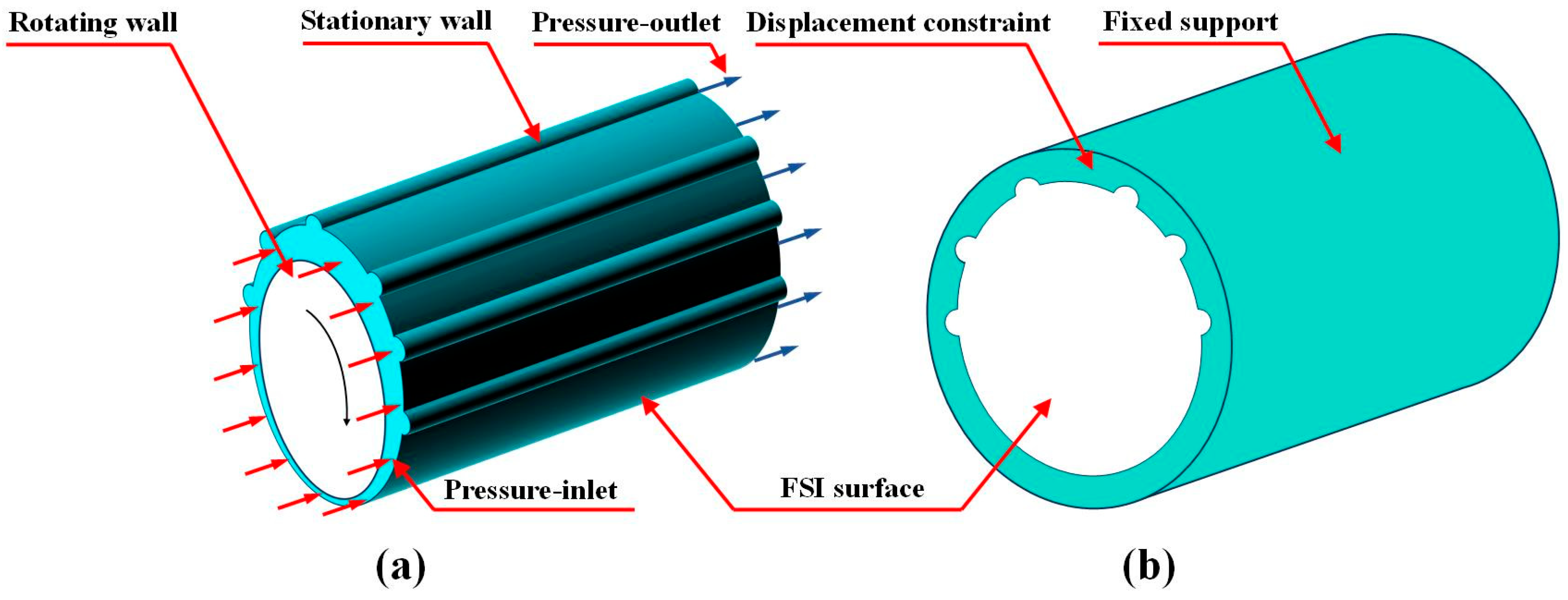
Figure 2 depicts the bearing’s boundary constraints. A multiphase flow coupling model is adopted, the weakening effect of salt sand particles on surface roughness is achieved through the discrete phase model (DPM). In Fluent, the DPM model is adopted, where salt sand particles are regarded as discrete phases, and the incident velocity of the particles is consistent with the flow rate of the salt water. The water supply mode of the bearing is axial water supply. When the shaft rotates, water flows in from one end face of the bearing and flows out from the other end face. The inlet and outlet boundary conditions adopt the pressurized inlet and zero-pressure outlet respectively. The outer surface of the lining layer is a fixed support surface and is subject to displacement constraints. The water film’s inner boundary rotates in unison with the shaft at identical angular velocity. The outer surface of the water film contacts the inner surface of the lining layer without rotating and is regarded as a stationary surface under the boundary conditions. The stationary and moving surfaces of the water film are non-slip, and the outer surface of the water film and the inner surface of the lining layer form an FSI (Fluid-Structure Interaction) surface.
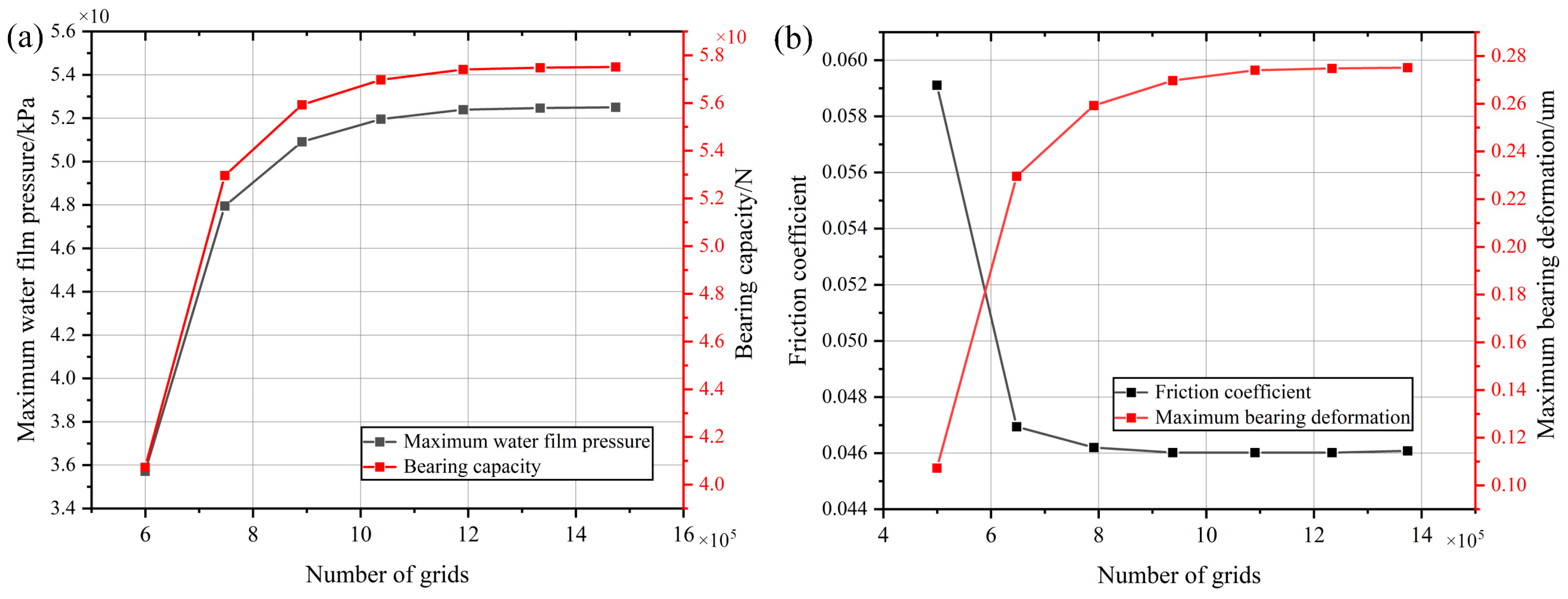
The meshing of the bearing is shown in Figure 3. A sweep-based meshing strategy is employed for the fluid domain, with the mesh element size being 0.3 mm. The hexahedral mesh is used for the solid domain, with the mesh element size being 2 mm. Compared with other meshes, the hexahedral mesh can provide higher computational accuracy in dealing with temperature and calculating heat conduction. Since Transient Structual defaults to Solid 185/186 mesh elements, and these elements cannot conduct heat transfer, Solid 226 elements are used in this paper. Figure 4 shows the verification of grid independence. In the FSI coupling calculation, the fluid is calculated first, and the fluid grid independence study is conducted first. Then, the solid is calculated, and the solid grid independence study is carried out again, The calculation results show that the mesh numbers of the fluid (0.3 mm) and the hexahedron (2 mm) have tended to stabilize. Further reducing the mesh size has a minimal impact on the results, and the mesh convergence requirements.

2.3. Solution Process

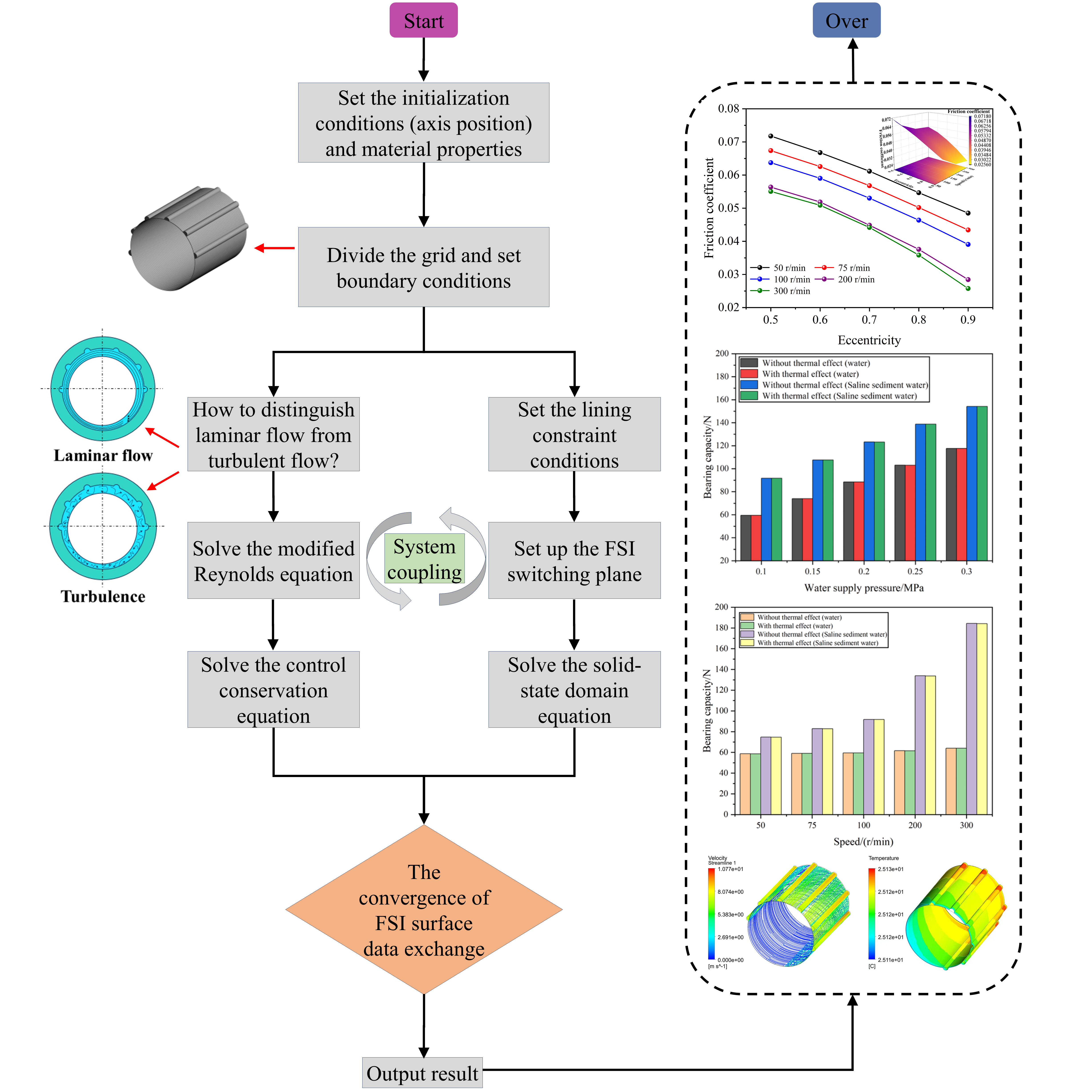
Figure 4 outlines the sequence of steps in the model computation. Firstly, the initial conditions and material properties were set. Then, meshing and boundary condition settings were carried out. The fluid-domain and solid-domain governing equations were handled by separate solvers, the water film pressure and temperature calculated in the fluid domain are transferred to the solid domain. Then, solve the solid-state domain control equations to obtain the deformation and temperature distribution of the bearing bushing. The deformation in the solid domain is then fed back to the fluid domain to complete one coupling iteration, and data exchange was conducted through the coupling interface, thus realizing the continuous update of the calculation results of the fluid domain and the solid domain.

3. Simulation Analysis

3.1. Lubrication Characteristics of Bearings Considering Thermal Effects at Different Rotational Speeds

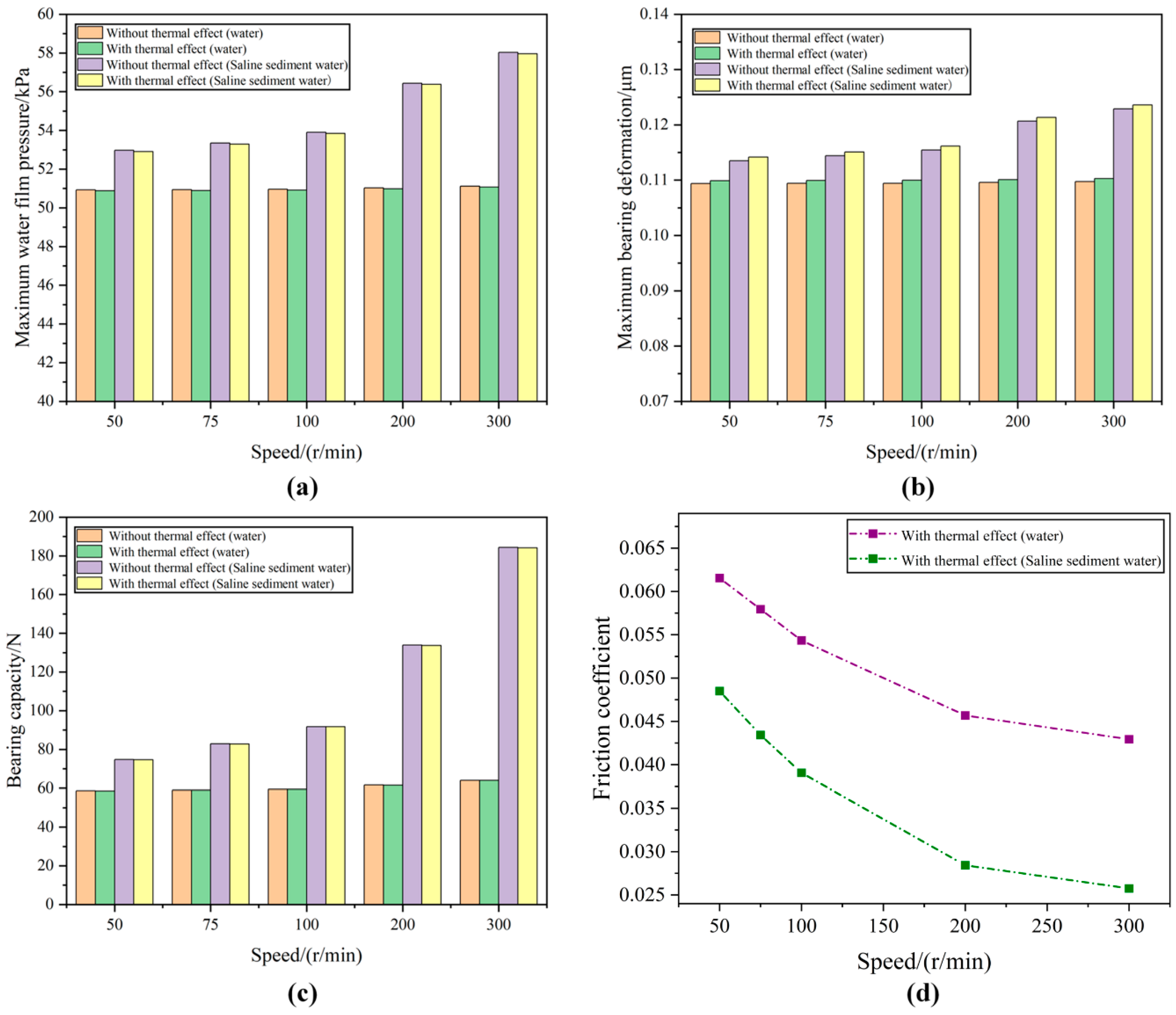
Figure 5 shows the distribution diagrams of the bearing lubrication characteristics without considering the thermal effect and with considering the thermal effect at different rotational speeds. Simulation working conditions: operating conditions span a shaft speed of 50–300 r/min, a feed-water pressure of 0.1 MPa, and a surface roughness of 1.422 μm, the eccentricity is 0.9, and the temperature is 25 °C. Figure 6a–c reveal that, whether in fresh water or salt–sand water, the peak water-film pressure, the largest bush deflection and the bearing capacity all rise steadily as shaft speed increases. The growth is the most significant in the salt-sand water area, with the maximum increase rate being 11.9%. This is because the concentration of salt-sand water is relatively high. Moreover, the salt-sand plays the role of a filler in the water film, and the salt-sand particles will also increase the turbulence degree of the water area and enhance the hydrodynamic pressure effect of the fluid, thus increasing the water film pressure, but also resulting in an increase in the bearing bush deformation amount. After considering the thermal effect, at the same rotational speed, the water-film pressure and load capacity decline marginally—by 0.11%—while the bush deformation exhibits a slight increase, with the increases of liquid water and salt-sand water being 0.47% and 0.6% respectively. This is because after considering the thermal effect, the mechanical load and the thermal load act on the surface of the bearing bush together, making the bearing bush bear a greater load and increasing the deformation amount of the bearing bush and the bearing clearance. In addition, thermal effects lower the water’s viscosity, leading to reductions in both film pressure and load capacity. As shown in Figure 6d, as the rotational speed increases, the bearing gradually transits from mixed lubrication to hydrodynamic lubrication. The friction coefficients of the bearings in both water areas decrease with the increase of the rotational speed. The decrease in the friction coefficient of the bearing in the salt-sand water area is the most significant. After the rotational speed reaches 100 r/min, Figure 6d shows that the slope of the straight line is relatively reduced, the hydrodynamic lubrication is gradually formed, and the decrease rate of the friction coefficient of the bearing in the salt-sand water area slows down, with the minimum value dropping to 0.026. The friction coefficient of liquid water drops from 0.062 to 0.043. Due to the high concentration of salt-sand water and the sand removal effect of the grooves, the bearing in the salt-sand water environment has good lubrication performance. Meanwhile, it further evidences PEEK’s inherently low friction and favorable self-lubrication characteristics.

3.2. Bearing Lubrication Characteristics After Considering Thermal Effects Under Different Water Supply Pressures

Figure 7 shows the distribution diagrams of the bearing lubrication characteristics with and without considering the thermal effect under different water supply pressures. Simulation working conditions: inlet water pressure is varied between 0.1 MPa and 0.3 MPa, the rotational speed is 100 r/min, the surface roughness is 1.422, the eccentricity is 0.9, and the temperature is 25 °C. As shown in Figure 7a–c, when the water supply pressure increases from 0.1 MPa to 0.3 MPa, peak hydrodynamic pressure, the deformation amount of the bearing bush, and the load-carrying capacity show a linear increasing trend, increasing to 104.21 kPa, 0.224 μm, and 154.15 N respectively. Compared with the rotational speed shown in Figure 5, the water supply pressure has the most significant impact on the bearing lubrication characteristics. This results from the progressive rise in water supply pressure, the lubricant can more thoroughly occupy the clearance between shaft and bearing, which is beneficial to the formation of the water film, thereby increasing the water film pressure and the load-carrying capacity, but also causing greater deformation of the bearing bush. Under the same working conditions, due to the axial flow water supply, a large amount of salt-sand fillers are discharged along the grooves. Therefore, compared with liquid water, the increase in salt-sand water is not as obvious as the rotational speed effect, and the increases in the water film pressure and the load-carrying capacity are reduced. Compared with the situation after considering the thermal effect, the changing trends of the water film pressure, the deformation of the bearing bush, and the load-carrying capacity are consistent with those of the bearing lubrication characteristics under different rotational speeds. Film pressure and load capacity dip marginally, whereas bush deformation exhibits a modest rise. This is because thermal expansion changes the bearing clearance, increases the deformation of the bearing bush, thereby lowering both the water-film pressure and the load capacity of the bearing. The deformations of the bearing bush in liquid water and salt-sand water areas increase by 0.47% and 0.45% respectively. As shown in Figure 7b,d, after considering the thermal effect, compared with liquid water, the deformation amount of the bearing bush in the salt-sand water area is smaller, and the friction coefficient decreases linearly, with the minimum value dropping to 0.02. This is because under the action of salt-sand particles, more heat is taken away along the grooves, reducing the impact of temperature on the bearing lubrication characteristics. Moreover, the concentration of salt-sand water is relatively high, and the presence of particles makes the surface filling effect of the bearing bush better. Meanwhile, it also indicates that the PEEK material water-lubricated bearing is not sensitive to temperature and has good friction and mechanical properties.

3.3. Distribution of Water Film Temperature Under Different Rotational Speeds and Different Water Supply Pressures

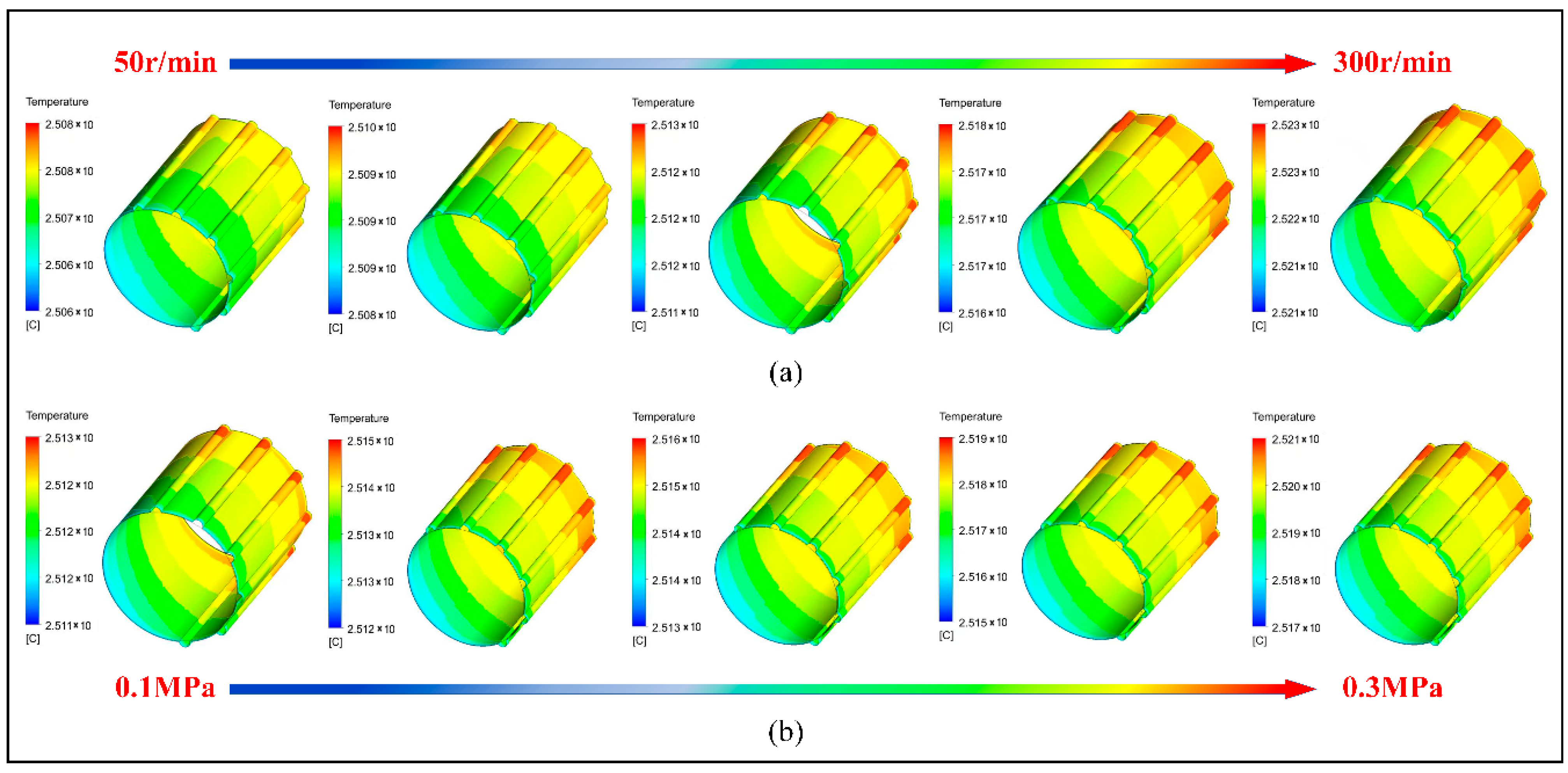
Figure 8 presents the temperature contour maps of the water film at varying rotational speeds and supply pressures. Simulation working conditions: operating parameters span 50–200 r/min shaft speed and 0.1–0.3 MPa water-supply pressure, the surface roughness is 1.422, and the temperature is 25 °C. Judging from the contour plots, the water film temperature increases slightly with the increase in the rotational speed and the water supply pressure. And due to the axial flow water supply and the temperature boundary being set as convection, the water film temperature increases in a gradient along the axial direction, and the highest temperature accumulates in the grooves at the outlet of the water film. There are two reasons for the above distribution. Firstly, the heat generated by the shear between the water film and the shaft as well as between the water film and the bearing bush will accumulate in the grooves. Secondly, when the journal rotates, eddy current shear will occur in the grooves to generate heat, and the axial water supply flow will carry the heat of the water film from the water supply end to the water outlet end, causing the temperature in the grooves at the water outlet end to rise. The maximum growth rate of the water film temperature affected by the rotational speed is 0.19%, and the maximum growth rate of the water film temperature affected by the water supply pressure is 0.08%. It can be seen from this that the impact of the rotational speed on the water film temperature is more significant. This is because, relative to rotational speed, higher feed pressure removes more heat via the grooves.

3.4. Bearing Lubrication Characteristics Under the Coupling of Eccentricity and Rotational Speed

The bearing load will affect the eccentricity between the bearing and the rotating shaft, and then influence the lubrication characteristics of the water-lubricated bearing. Simulation working conditions: the eccentricity ranges from 0.5 to 0.9, shaft speed spans 50–200 r/min, inlet pressure is fixed at 0.1 MPa, and surface roughness remains 1.422 µm, and the temperature is 25 °C. Figure 9 shows the lubrication characteristics of the bearing under the coupling of eccentricity and rotational speed. It can be seen from Figure 9a that the water film pressure increases with the increase in the eccentricity and the rotational speed. Compared with the eccentricity, the rotational speed exerts a stronger influence on water-film pressure. The deformation amount of the bearing bush increases with the increase in the eccentricity and the rotational speed. Judging from Figure 8b, under the high rotational speed in the salt-sand water area, the influence of the eccentricity on the deformation of the bearing bush is more significant. This is because the high rotational speed drives more salt-sand particles, increasing the impact frequency and intensity of the particles on the bearing bush. At this point, bush deformation arises from both hydrodynamic pressure and the additional impact of salt-sand particles. Figure 9c reveals that increasing eccentricity accentuates the wedge-shaped clearance between journal and bearing, and the bearing gradually transits to hydrodynamic lubrication, with the friction coefficient continuously decreasing and reaching a minimum value of 0.025. Judging from the contour plots, the rotational speed has a more significant impact on the friction coefficient.

3.5. Bearing Lubrication Characteristics Under the Coupling of Roughness and Rotational Speed

Figure 10 shows the distribution diagrams of the bearing lubrication characteristics under the coupling of the bearing bush surface roughness and the rotational speed. Simulation working conditions: the surface roughness ranges from 0.622 to 3.822, shaft speed is varied from 50 to 200 r/min, with water supply pressure fixed at 0.1 MPa and eccentricity set at 0.9, and the temperature is 25 °C. It can be seen from Figure 10a that the water film pressure increases slightly with the increase in the surface roughness and decreases with the increase in the rotational speed. When the salt-sand water flows in the bearing gap to form a water film, the surface asperities of the bearing will interfere with the smoothness of the water flow. When the water flow passes through the asperities, the ordered flow of the salt-sand water is hindered, increasing the kinetic energy loss of the water flow, thus leading to a decrease in the water film pressure. At the same time, under this state, part of the water film pressure is borne by the asperities, resulting in a slight decrease in the water film pressure. As shown in Figure 10b, bush deformation closely tracks water-film pressure trends, as the latter remains its dominant contributor, but the decrease amplitude is not large. This is because the presence of the surface asperities allows the salt-sand to fill the gaps between the asperities, and part of the load will be borne by the salt-sand particles, weakening the influence of the water film pressure on the bearing bush deformation. At the same time, when the rotational speed is greater than 100 r/min, the water film pressure increases significantly, and the hydrodynamic lubrication is the strongest at this time. As shown in Figure 10c, with increasing surface roughness of the bearing, the friction coefficient shows an upward trend. The larger bush roughness raises the hydrodynamic drag within the water film, giving rise to this trend. At low rotational speeds, the friction coefficient is relatively high, and at high rotational speeds, the water film is more likely to form, and the friction coefficient decreases. Generally speaking, under this coupling working condition, the rotational speed has a more significant impact on the lubrication characteristics of the bearing.

3.6. Distribution of the Flow Velocity of the Water Film Flow Field Under Different Rotational Speeds and Different Eccentricities

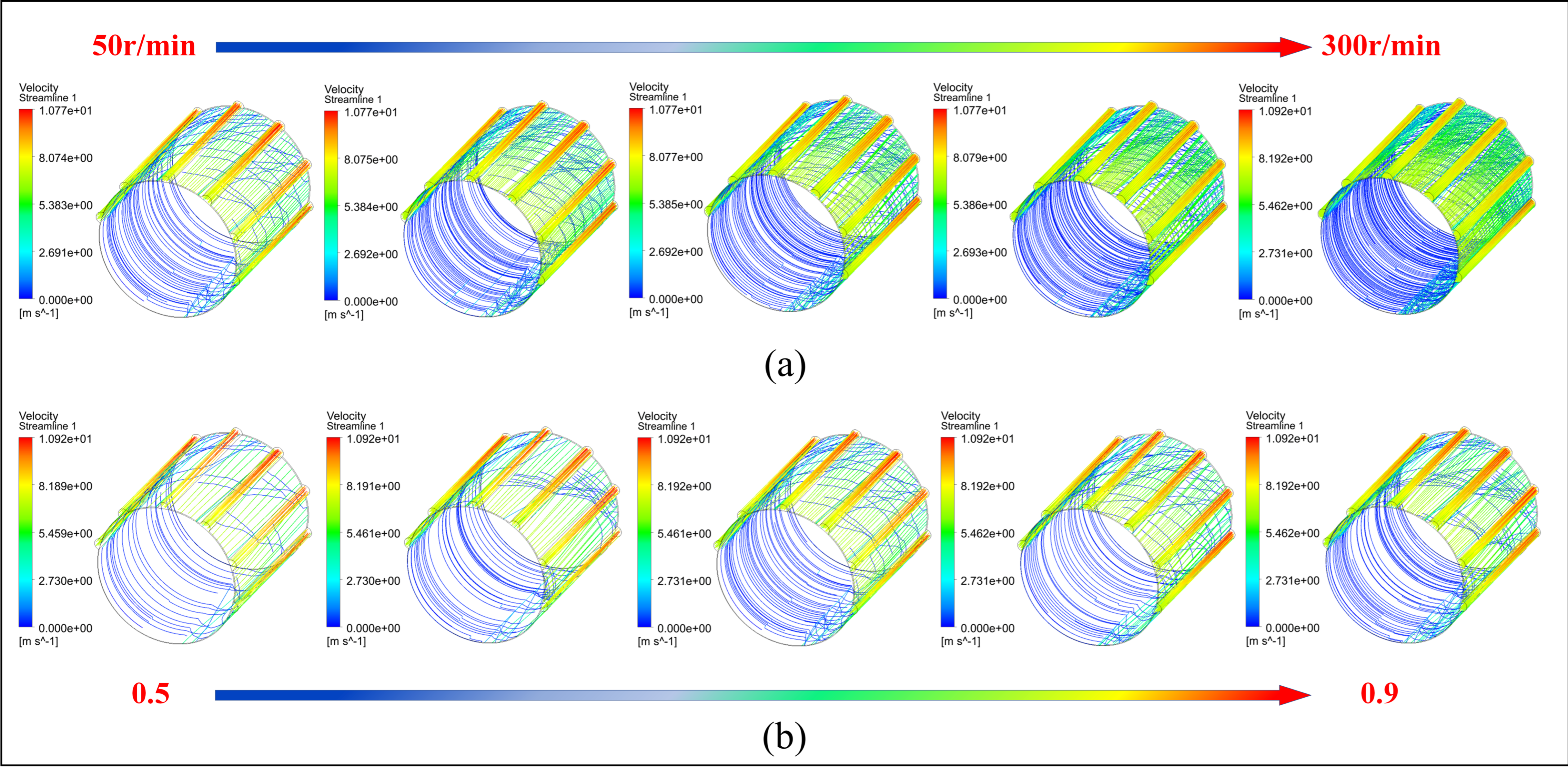
Figure 11 shows the distribution diagrams of the flow velocity of the water film flow field in the water-lubricated bearing under different rotational speeds and different eccentricities. Simulation working conditions: shaft speed is varied from 50 rev/min to 200 r/min, the eccentricity ranges from 0.5 to 0.9, the water supply pressure is 0.1 MPa, and the surface roughness is 1.422. It can be seen from the figure that the changing trends of the water film flow velocity with the rotational speed and the eccentricity are consistent. With the increase in the shaft rotational speed, the flow velocity of the water film flow field increases, and the water flow trace lines become denser. As shown in Figure 11a, at low rotational speeds, the water flows slowly along the inner wall of the bearing, the velocity vector is small, and the water film is not completely formed. With rising rotational speed, the flow velocity of the fluid increases significantly, the flow of the water inside the bearing becomes more complex, forming eddy currents and backflow phenomena. The circumferential shear force of the water film in the load-bearing area is enhanced, and the axial shear force of the water flow in the non-load-bearing area is enhanced, which exactly achieves the design effect of the local upper half grooves. The maximum difference in the water film flow velocity is 0.015 m/s. After 75 r/min, the full-film lubrication is formed. Figure 11b shows the distribution diagrams of the flow velocity of the water film flow field under different eccentricities. Under low eccentricities, the full-film lubrication is not completely formed. As the eccentricity increases, the bearing’s lubrication regime shifts from boundary to fully hydrodynamic. The maximum difference in the water film flow velocity between the eccentricity of 0.9 and that of 0.5 is 0.003 m/s. After the eccentricity reaches 0.7, the water film trace lines in the load-bearing area increase, the full-film lubrication becomes more obvious, and the flow velocity in the grooves is the highest. Therefore, the design of the local upper half grooves can not only improve the load-carrying capacity but also discharge the salt-sand particles through the grooves as soon as possible.

4. Experimental Test

4.1. Test Environment and Test Bench

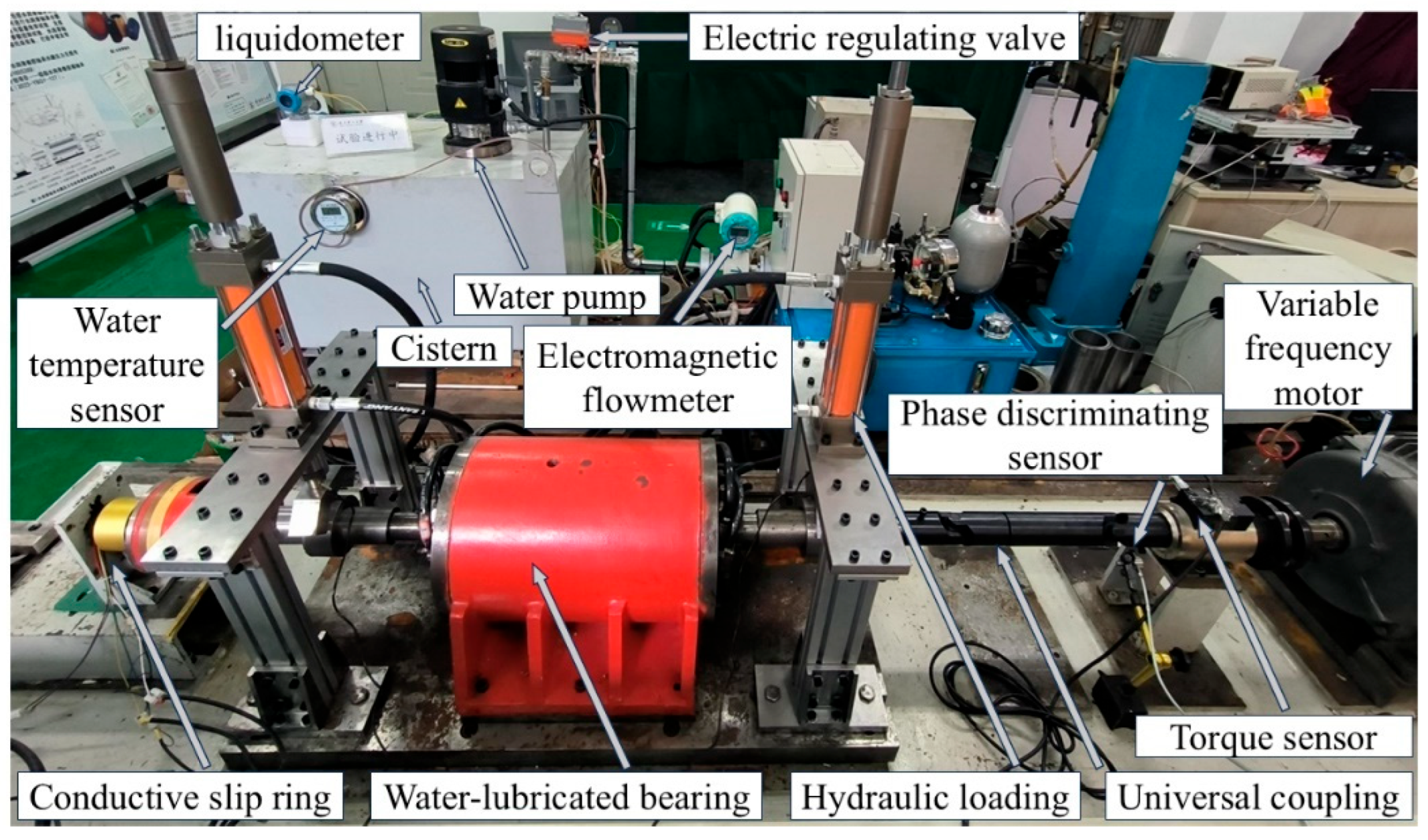
To verify the above theories and physical models, multi-condition and multi-factor experimental studies were conducted on PEEK water-lubricated bearings. The experimental setup for the water-lubricated bearing is depicted in Figure 12. The test bench includes a variable frequency motor (for speed regulation), a water supply electrical regulating valve (for water supply pressure), a hydraulic loading device (for loading force), a digital water temperature display meter (for water temperature), a torque sensor (for friction coefficient), and the roughness tester mentioned in the test conditions. Meanwhile, in order to accurately obtain the pressure distribution of the water film for one week, a phase detection sensor is set up.
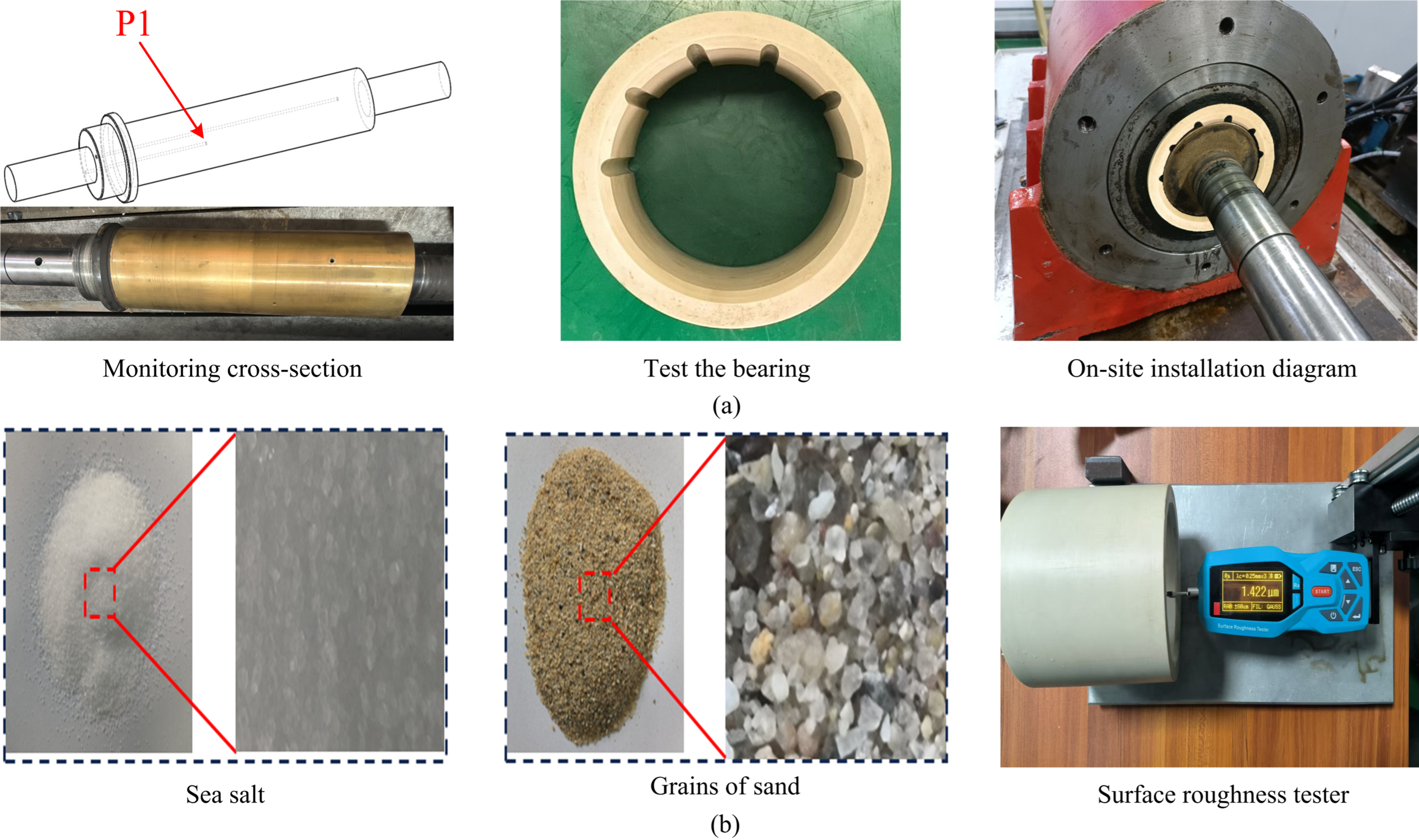
The bearing test conditions are shown in Figure 13, including structural parameters (local upper half six-groove bearing), lubricating medium (saline sand water), and one of the test conditions (surface roughness tester). The section of the water film pressure monitoring points is set at a distance of 50 mm from the water supply inlet. The surface test of the bearing was conducted using the surface roughness tester shown in Figure 13b, with a test accuracy of 0.001 μm.

4.2. Water Film Pressure Tests of Bearings Under Different Working Conditions

Figure 14 is a comparison diagram between the simulation and experiment of the water film pressure under different working conditions. It can be seen from Figure 14a that when the rotational speed ranges from 50 r/min to 300 r/min, the inlet water pressure is set at 0.1 MPa, the surface roughness is 1.422, the eccentricity ratio is 0.9, and the temperature is 25 °C, the water film pressure increases with the increase of the rotational speed. Under the same working condition, the water film pressure of the saline sand water is greater than that of the liquid water, and the maximum increase is 1.42 kPa. Figure 14b shows the distribution of the change in the water film pressure when the water supply pressure ranges from 0.1 MPa to 0.3 MPa, the rotational speed is 100 r/min, the load is 27 N, and the temperature is 25 °C. Film pressure rises as supply pressure is elevated. Compared with the rotational speed, the increase in the water film pressure under a high water supply pressure is more obvious, with the maximum increase being 23.66 kPa. The hydrodynamic lubrication is more obvious under this working condition. Figure 14c shows the change in the water film pressure when the load ranges from 28 N to 83 N, the water supply pressure is 0.1 MPa, the rotational speed is 100 r/min, and the temperature is 25 °C. As the load increases, the wedge effect of the bearing becomes more obvious, and the water film pressure rises, with the maximum increase being 0.72 kPa. Generally speaking, compared with the water supply pressure, the curves of the water film pressure with respect to the rotational speed and the load show a slow growth and fluctuations, and the hydrodynamic lubrication is not so obvious at this time. Compared with the liquid water, the water film pressure of the saline sand water increases as a whole, indicating that the bearing has better lubrication characteristics in the saline sand water environment. The simulation results are consistent with the experiment in terms of the trend and are in line with the simulation conclusions. However, the experimental values are slightly smaller than the simulation values, and the maximum errors in the three working conditions are all around 10%.

4.3. Tests on the Friction Coefficient of Bearings Under Different Working Conditions

Figure 15 contrasts simulated and measured friction coefficients across the tested operating conditions. The friction coefficient of the bearing in the saline sand water is generally lower than that in the liquid water. At a water supply pressure of 0.3 MPa, the friction coefficient can drop to 0.019, which reflects that although there are salt and sand particles in the saline sand water, the local upper half groove bearing can still exhibit good lubrication characteristics. However, under the same water environment, the experimental values are slightly smaller than the simulation values, and the errors become smaller as the rotational speed, water supply pressure and load increase. The minimum error of the friction coefficient can reach 2.6%, indicating that the system becomes more stable as the rotational speed, water supply pressure and load increase. After analysis, there are three reasons for the errors in the water film pressure and friction coefficient. First, there will be pressure losses in the water supply pipeline. Second, the control systems for the rotational speed, water supply pressure and load are not accurate enough. Third, in the simulation, the material properties are usually uniform and the boundary conditions are ideal.

5. Conclusions

In order to study the lubrication characteristics of a new type of water-lubricated bearing made of PEEK material and provide a theoretical reference for the application of this material in water-lubricated bearings, a half-circle groove model of a PEEK water-lubricated bearing was established. Using a multi-field coupling method, the lubrication and friction characteristics of the bearing under the influence of multiple factors in a saline sand water environment were studied and analyzed. Finally, tests and verifications were carried out on a test rig for the dynamic characteristics of water-lubricated bearings, and multi-factor bearing lubrication characteristic tests were conducted. Key findings are summarized below:
(1)
In a saline sand water environment, the maximum water film pressure, bush deformation, and bearing capacity of the bearing all increase with increasing rotational speed and water supply pressure. As the eccentricity increases, the bearing wedge gap increases, the friction coefficient decreases, and the hydrodynamic effect becomes significant. An increase in the surface roughness of the bush leads to a slight decrease in the water film pressure and bush deformation and an increase in the friction coefficient. However, the presence of salt and sand particles can fill the gaps between asperities, weakening the negative impact of roughness on lubrication performance. Meanwhile, the high viscosity of saline sand water and the filling effect of the particles enhance the hydrodynamic effect of the fluid, making the lubrication performance of the bearing superior to that in liquid water.
(2)
After considering the thermal effect, the mechanical and thermal loads act together on the bush. The maximum bush deformation increases by 0.47% and 0.6% in liquid water and saline sand water, respectively, while the water film pressure and bearing capacity both slightly decrease by 0.11%. This indicates that the thermal effect reduces the lubrication effect of the fluid. The water film temperature increases slightly with increasing rotational speed and water supply pressure, and due to axial flow water supply and temperature boundaries, the highest temperatures accumulate in the grooves at the water film outlet.
(3)
The local upper half-groove structure can still exhibit good lubrication characteristics even in the presence of salt and sand particles. It not only improves the bearing capacity but also facilitates the discharge of water film temperature and salt and sand particles through the grooves. The PEEK water-lubricated bearing also demonstrates insensitivity to temperature, low friction, and good mechanical properties, with a minimum friction coefficient of up to 0.019.

Author Contributions

First Draft Writing and Data Analysis, H.J.; Guide research and obtain research funds, N.W.; Data Analysis, J.Q. and Z.Z.; Draw charts, M.Z.; Provide guidance on the framework of the thesis, J.W. and A.L.; Investigation Research and Paper Review, Y.C. and P.W. All authors have read and agreed to the published version of the manuscript.

Funding

Key Research and Development Program Project of Shaanxi Province (2023-YBGY-127, 2024GX-YBXM-198), Hanzhong, Shaanxi 723001; Special Research Program Project for Serving Local Areas of Shaanxi Province (22JC025) Hanzhong, Shaanxi 723001; Shaanxi University of Technology Graduate Innovation Fund Project (SLGYCX2515).

Data Availability Statement

Research data are not shared.

Conflicts of Interest

The authors declare no conflict of interest.

References

  1. Yan, X.; Liang, X.; Liu, Z. Research progress of marine water lubricated stern bearing. Ship Build. China 2017, 58, 221–232. [Google Scholar]
  2. Zhou, X.; Kuang, F.; Huang, J. Water-lubricated stern bearing rubber layer construction and material parameters: Effects on frictional vibration based on computer vision. Tribol. Trans. 2021, 64, 65–81. [Google Scholar] [CrossRef]
  3. Zhang, Z.; Ouyang, W.; Liang, X. Review of the evolution and prevention of friction, wear, and noise for water-lubricated bearings used in ships. Friction 2024, 12, 1–38. [Google Scholar] [CrossRef]
  4. Jiang, S.; Wong, J.; Puhan, D. Tribological evaluation of thermoplastic polyurethane-based bearing materials under water lubrication: Effect of load, sliding speed, and temperature. Friction 2024, 12, 1801–1815. [Google Scholar] [CrossRef]
  5. Zhang, G.; Zhang, C.; Nardin, P. Effects of sliding velocity and applied load on the tribological mechanism of amorphous poly-ether–ether–ketone (PEEK). Tribol. Int. 2008, 41, 79–86. [Google Scholar] [CrossRef]
  6. Shukla, D.; Negi, Y.S.; Uppadhyaya, J.S. Synthesis and modification of poly (ether ether ketone) and their properties: A review. Polym. Rev. 2012, 52, 189–228. [Google Scholar] [CrossRef]
  7. Panayotov, I.V.; Orti, V.; Cuisinier, F. Polyetheretherketone (PEEK) for medical applications. J. Mater. Sci. Mater. Med. 2016, 27, 118. [Google Scholar] [CrossRef]
  8. Han, Y.; Yin, L.; Xiang, G. An experimental study on the tribological performance of water-lubricated journal bearings with three different materials. Ind. Lubr. Tribol. 2020, 72, 1159–1165. [Google Scholar] [CrossRef]
  9. Ma, H.Q.; Wang, Y.Q.; Liu, X.F. Research Progress on Friction and Wear of Water Lubricated Bearing Modified PEEK Materials. Bearing 2023, 11, 1–12. [Google Scholar]
  10. Xie, Z.L.; Jiao, J.; Yang, M. Investigation on the Fluid-structure-acoustic Multi-field Interaction Characteristics of the Water-lubricated Sandwich Liner Bearing. J. Mech. Eng. 2024, 60, 340–349. [Google Scholar]
  11. Litwin, W.; Wasilczuk, M.; Wodtke, M. The influence of polymer bearing material and lubricating grooves layout on wear of journal bearings lubricated with contaminated water. Tribol. Int. 2023, 179, 108159. [Google Scholar] [CrossRef]
  12. Liu, Q.; Ouyang, W.; Li, R. Experimental exploration on the nonlinear dynamic behavior of marine propeller shaft-bearing system. Ocean Eng. 2024, 310, 118595. [Google Scholar] [CrossRef]
  13. Lv, F.; Jiao, C.; Jia, Q. Influence of structural and operating parameters on lubrication performance of water-lubricated polymer bearing with journal misalignment. Lubricants 2022, 10, 336. [Google Scholar] [CrossRef]
  14. Wodtke, M.; Litwin, W. Water-lubricated stern tube bearing−experimental and theoretical investigations of thermal effects. Tribol. Int. 2021, 153, 106608. [Google Scholar] [CrossRef]
  15. Ouyang, W.; Zhang, Z.; Nie, Y.; Liu, B.; Vanierschot, M. Parametric modeling and collaborative optimization of a rim-driven thruster considering propeller-duct interactions. Ocean Eng. 2025, 337, 121746. [Google Scholar] [CrossRef]
  16. Xie, Z.L.; Zhang, H.; Yang, M. Research on the Influence of Bidirectional Misalignment on the Lubrication Characteristics of Water-Lubricated Grooved Bearings. Tribology 2024, 11, 1–17. [Google Scholar]
  17. Chen, Y.H.; Wang, N.; Wang, M.W. Study on Effect Mechanism of Bi-directional Journal Tilt on Characteristics of Water-Lubricated Stern Bearings. Mech. Sci. Technol. Aerosp. Eng. 2025, 44, 994–1002. [Google Scholar]
  18. Liu, Q.; Ouyang, W.; Cheng, Q. Influences of bidirectional shaft inclination on lubrication and dynamic characteristics of the water-lubricated stern bearing. Mech. Syst. Signal Process. 2022, 169, 108623. [Google Scholar] [CrossRef]
  19. Ouyang, W.; Liu, Q.; Jin, Y.; Dong, X. Semi-active control for transverse vibration of ship propulsion shafting with magnetorheological squeeze film damper. Mech. Syst. Signal Process. 2025, 233, 112763. [Google Scholar] [CrossRef]
  20. Chen, P.; Wang, T.; Ma, W. Characteristic analysis of water lubricated plain journal bearing under transient load. J. Phys. Conf. Ser. 2022, 2160, 012073. [Google Scholar] [CrossRef]
  21. Wu, J.; He, T.; Zhang, F. Influence of Bearing Bush Elastic Deformation on Bearing Performance of Water-Lubricated Bearings. China Offshore Platf. 2022, 37, 33–37. [Google Scholar]
  22. Yang, H.; Yan, K.H.; Huang, D. Analysis on journal bearing’s lubrication characteristics with thermo-fluid-solid coupling taken into account. J. Mach. Des. 2022, 39, 10–16. [Google Scholar]
  23. Wu, Z.; Yuan, C.; Guo, Z. Effect of the groove parameters on the lubricating performance of the water-lubricated bearing under low speed. Wear 2023, 522, 204708. [Google Scholar] [CrossRef]
  24. Zhang, X.; Liang, X.X.; Xiang, Y.K. Experimental Study on the Friction and Vibration Performance of Water-Lubricated Bearings with Different Groove Structures. Lubr. Eng. 2025, 50, 118–125. [Google Scholar]
  25. Yang, C.; Zhou, X.; Huang, J. Effects of sediment size and type on the tribological properties of NBR in water. Wear 2021, 477, 203800. [Google Scholar] [CrossRef]
  26. Hu, D.; Guo, Z.W.; Yuan, C.Q. Influence of Sand Particles on Water Lubrication of UHMWPE Material. Ship Eng. 2019, 41, 98–104. [Google Scholar]
  27. Leng, Z.; Lv, F.; Zhang, J. Study of dynamic coefficients of water film in marine sterntube bearing considering roughness and deformation. Proc. Inst. Mech. Eng. Part J J. Eng. Tribol. 2021, 235, 2257–2271. [Google Scholar] [CrossRef]
  28. Charamis, D.; Nikolakopoulos, P.G. Investigation of cavitated flow in water-lubricated bearings considering surface roughness, thermal, and elastic effects. Lubricants 2024, 12, 107. [Google Scholar] [CrossRef]
  29. Yang, H.; Ouyang, W.; Jin, Y. Study on the Elastohydrodynamic Lubrication of Marine Water Lubricated Polymer Bearings Considering Roughness. Lubr. Eng. 2023, 48, 45–50. [Google Scholar]
  30. Wang, L.L.; Duan, J.D.; Li, L.C. Performance of Water-lubricated Composite Micro-texture Thrust Bearing Considering Roughness. Surf. Technol. 2023, 52, 256–265, 409. [Google Scholar]
  31. Li, Q.; Liu, X.L.; Zhang, Z. Mixed Lubrication Performances of Water-Lubricated Bearing Materials Under Low Speed Conditions. Bearing 2024, 32, 84–91. [Google Scholar]
  32. Cao, Y.Z.; Liang, P.; Guo, F. Effects of Surface Roughness on Transient Performance of Water Lubricated Bearings During Start-Up under Different Working Conditions. J. Propuls. Technol. 2022, 43, 457–469. [Google Scholar]
  33. Xie, Z.L.; Jiao, J.; Yang, K. Theoretical and experimental study on the fluid-structure-acoustic coupling dynamics of a new water lubricated bearing. Tribol. Int. 2023, 177, 107982. [Google Scholar] [CrossRef]
  34. Patir, N.; Cheng, H.S. An Average Flow Model for Determining Effects of Three-Dimensional Roughness on Partial Hydrodynamic Lubrication. Trans. ASME J. Lubr. Technol. 1978, 100, 12–17. [Google Scholar] [CrossRef]
  35. Patir, N.; Cheng, H.S. Application of Average Flow Model to Lubrication Between RoughSliding Surfaces. Trans. ASME J. Lubr. Technol. 1979, 101, 220–230. [Google Scholar] [CrossRef]
  36. Jing, H.B.; Wang, N.; Li, D.H. Analysis on Lubrication Characteristics of a Novel Strain Sensor-Embedded Water-Lubricated Bearing. Lubr. Eng. 2024, 12, 1–10. [Google Scholar]
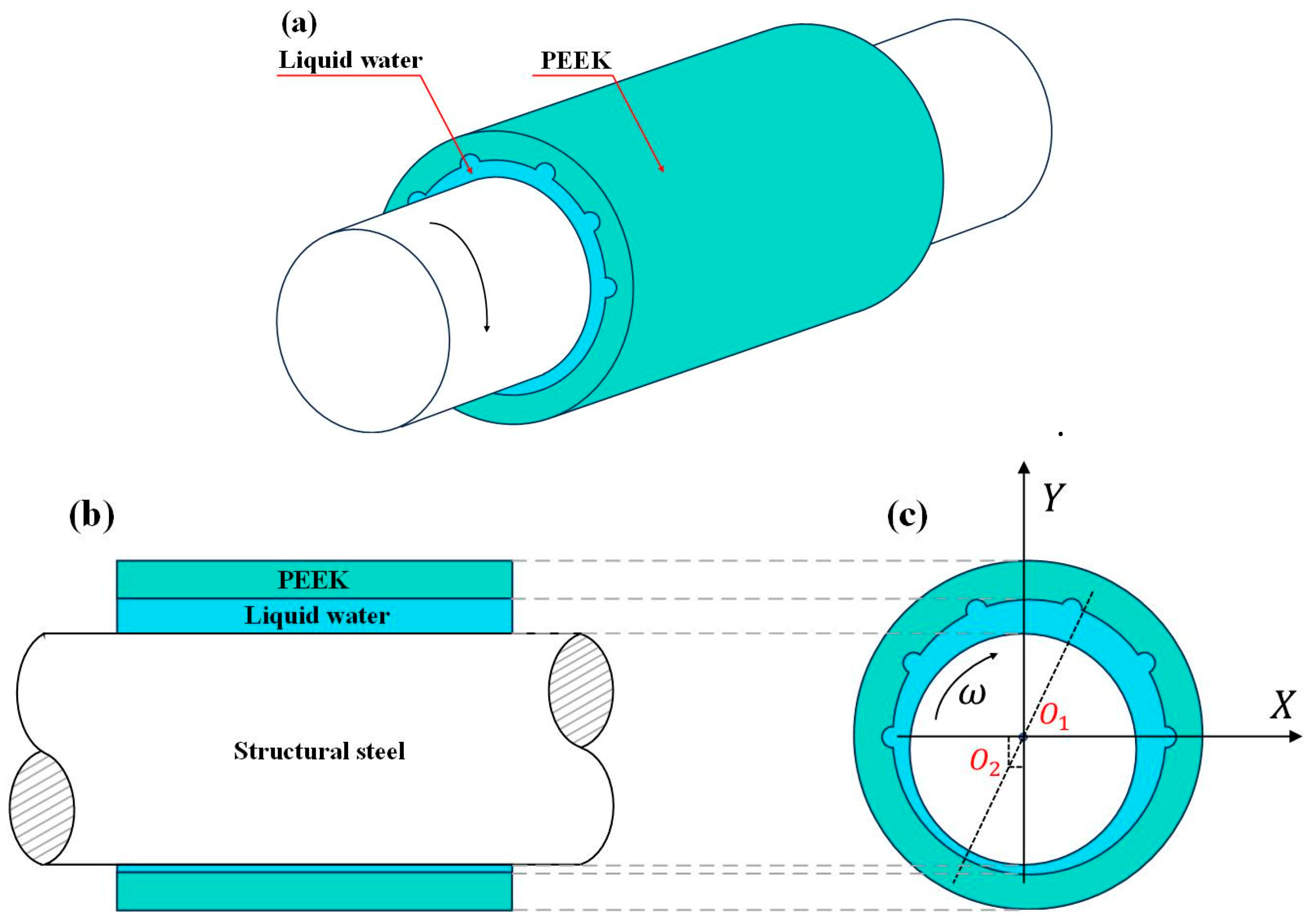
Figure 1. Water-lubricated bearing: (a) Three-dimensional model. (b) Side view. (c) Front view.
Lubricants 13 00470 g001
Figure 2. Boundary conditions: (a) Fluid domain. (b) Solid domain.
Lubricants 13 00470 g002
Figure 3. Meshing: (a) Fluid domain. (b) Solid domain.
Lubricants 13 00470 g003
Figure 4. Grid independence verification: (a) Fluid. (b) Solid.
Lubricants 13 00470 g004
Figure 5. Calculation flow chart.
Lubricants 13 00470 g005
Figure 6. Bearing lubrication characteristics at different rotational speeds: (a) Water film pressure. (b) Deformation amount of bearing bush. (c) Load-carrying capacity. (d) Friction coefficient.
Lubricants 13 00470 g006
Figure 7. Bearing lubrication characteristics under different water supply pressures: (a) Water film pressure. (b) Deformation amount of bearing bush. (c) Load-carrying capacity. (d) Friction coefficient.
Lubricants 13 00470 g007
Figure 8. Water film temperature: (a) Under different rotational speeds. (b) Under different water supply pressures.
Lubricants 13 00470 g008
Figure 9. Bearing lubrication characteristics under the coupling of eccentricity and rotational speed: (a) Water film pressure. (b) Deformation amount of bearing bush. (c) Friction coefficient.
Lubricants 13 00470 g009
Figure 10. Bearing lubrication characteristics under the coupling of roughness and rotational speed: (a) Water film pressure. (b) Deformation amount of bearing bush. (c) Friction coefficient.
Lubricants 13 00470 g010
Figure 11. Flow velocity distribution in the water film flow field: (a) At different rotational speeds. (b) Under different eccentricities.
Lubricants 13 00470 g011
Figure 12. Test bench for dynamic characteristics of water-lubricated bearings.
Lubricants 13 00470 g012
Figure 13. Test Conditions: (a) Bearing installation. (b) Lubricating medium and one of the test conditions.
Lubricants 13 00470 g013
Figure 14. Comparison between the simulation and experiment of water film pressure under different working conditions: (a) Different rotational speeds. (b) Different water supply pressures. (c) Different loads.
Lubricants 13 00470 g014
Figure 15. Comparison between Simulation and Experiment of Friction Coefficient under Different Working Conditions: (a) Different rotational speeds. (b) Different water supply pressures. (c) Different loads.
Lubricants 13 00470 g015
Table 1. Structural and material parameters of the PEEK water-lubricated bearing.
Structural ParametersParameter ValueMaterial ParametersParameter Value
Bearing length, L/mm120Density, ρ/(kg · m−3)1300
Bearing outer diameter, D1/mm130Poisson’s ratio, β/k−10.4
Bearing inner diameter, D2/mm100Elastic modulus, /GPa3.5
Journal radius, R/mm99.2Thermal conductivity, k/(W · m−1 · K−1)0.29
Radius of the groove, h/mm4Coefficient of thermal expansion, β/K−15.5 × 10−5
Number of grooves, N6Specific heat, C/(J · kg−1 · K−1)2200
Table 2. Parameters of the lubricating medium for the PEEK water-lubricated bearing.
Lubricating MediumDensity, kg/m−3Viscosity, kg/m−sParticle Size, μm
Liquid water998.20.001003-
Sea salt1026.80.0010850.1
Saline sand water16500.50.5
Disclaimer/Publisher’s Note: The statements, opinions and data contained in all publications are solely those of the individual author(s) and contributor(s) and not of MDPI and/or the editor(s). MDPI and/or the editor(s) disclaim responsibility for any injury to people or property resulting from any ideas, methods, instructions or products referred to in the content.