Article

Unraveling the Friction and Wear Mechanisms of a Medium-Carbon Steel with a Gradient-Structured Surface Layer

1
CGN Wind Power Co., Ltd., Beijing 100070, China
2
College of Mechanical Engineering, Zhejiang University of Technology, Hangzhou 310023, China
*
Author to whom correspondence should be addressed.
Lubricants 2025, 13(10), 448; https://doi.org/10.3390/lubricants13100448 (registering DOI)
Submission received: 12 September 2025 / Revised: 10 October 2025 / Accepted: 11 October 2025 / Published: 14 October 2025
(This article belongs to the Special Issue Tribological Performance of Steels)

Abstract

This study investigates the enhancement of tribological performance in coarse-grained (CG) 42CrMo steel through the development of gradient-structured (GS) samples using double-sided symmetrical surface mechanical rolling treatment (D-SMRT). Dry reciprocating sliding wear tests are performed against a GCr15 steel counter ball to evaluate the influence of normal load on the wear resistance of CG and D-SMRT samples. Results demonstrate that D-SMRT significantly improves wear resistance under a 5 N load, attributed to the synergistic effects of surface strengthening and microstructure refinement. Characterization of worn surfaces via scanning electron microscopy (SEM) and energy-dispersive spectroscopy (EDS) confirms oxidative wear and abrasive wear as the dominant mechanisms at 5 N. With increasing load, wear transitions to abrasive and fatigue wear for the CG sample, while adhesive wear and plastic deformation dominate in the GS sample. This work concludes that D-SMRT technology effectively enhances the tribological properties of 42CrMo steel under normal loads below 10 N.

1. Introduction

42CrMo steel, a representative medium-carbon low-alloy steel, exhibits high strength, excellent toughness, and superior wear resistance, leading to its extensive industrial application in components such as bolts, automotive crankshafts, and transmission gears [1,2,3,4]. These metallic parts are susceptible to wear-induced failure during service. Engine connecting rods, for instance, endure complex loading conditions, including cyclic stresses from piston reciprocation, rotational loading, and piston pin friction [5], making the synergistic interaction between wear and fatigue a critical failure mechanism. Similarly, bolts frequently undergo seizure failure under ambient conditions due to unlubricated reciprocating sliding, primarily caused by wear debris accumulation and clogging [6,7]. While component replacement remains feasible, the process entails significant time, labor, and financial expenditures. Consequently, enhancing machinery service life through improved tribological performance of metal surfaces represents an essential approach for industrial advancement.
Since its inception, the concept of nanostructured materials has garnered significant research interest [8,9]. Compared to their coarse-grained (CG) counterparts, nanostructured materials possess refined grain sizes, increased interfacial volume fractions, and elevated defect densities, imparting superior strength and hardness. However, their limited work-hardening capacity often compromises ductility [10]. Numerous studies indicate that the high hardness of nanostructured materials can mitigate wear loss under sliding contact, enhancing wear resistance [11,12,13,14]. Conversely, Zhou et al. [15] reported that nanostructured AISI 52100 steel, despite its high hardness, exhibited no improvement in wear resistance over its CG equivalent due to insufficient ductility. An optimal combination of high hardness and moderate plasticity is therefore essential to effectively suppress crack initiation and propagation during sliding wear.
Inspired by heterogeneous structures in nature, gradient nanostructures have been proposed to overcome the strength–ductility trade-off in conventional homogeneous nanomaterials [16]. Gradient nanostructures feature depth-dependent variations in dimension, volume fraction and type of microstructural unit. This architecture facilitates synergistic deformation mechanisms across multiple length scales, optimizing mechanical properties to achieve an exceptional strength–ductility balance and enhanced wear resistance [17,18,19,20]. Nevertheless, mechanically induced gradient nanostructured surface layer in magnesium alloys exhibited compromised ductility and toughness, resulting in detrimental wear performance [21]. Notably, Sun et al. [22] reported that surface mechanical attrition treatment of 304 stainless steel yielded wear mechanisms comparable to untreated material, showing no significant improvement under dry sliding conditions.
Surface strengthening techniques can induce surface nanocrystallization and compressive residual stress in metallic materials, modifying surface microstructure and mechanical properties to enhance fatigue and tribological performance [23,24,25,26]. Surface mechanical rolling treatment (SMRT), a prominent technique, achieves surface self-nanocrystallization while preserving chemical composition [27]. SMRT-processed materials develop plastically deformed layers of significant depth alongside superior surface finish. Research confirms that SMRT effectively produces nanocrystalline surface layers on diverse metallic substrates. For AISI 316L stainless steel, Wang et al. [28] demonstrated that the SMRT-induced gradient nanostructured surface layer combined high strain accommodation capability with elevated hardness, significantly improving wear resistance under both dry sliding and oil-lubricated conditions. Wang et al. [29] utilized SMRT to fabricate an exceptionally thick gradient nanostructured layer on Inconel 625 alloy. The improvement of elevated-temperature wear resistance was attributed to the exceptional thermal stability and retained hardness of the gradient nanostructure during sliding contact. Furthermore, Wang et al. [30] applied SMRT to 1060 aluminum rods, concluding that increased near-surface microhardness exerted a more pronounced influence on dry sliding wear behavior than surface roughness reduction. Despite these findings, the influence of SMRT on the wear resistance of 42CrMo steel and its underlying strengthening mechanisms remain unclear. Consequently, systematic investigation of the tribological behavior and wear-resistant mechanisms of gradient-structured (GS) 42CrMo steel is essential to realize the potential application of SMRT to medium-carbon steels.
Current research on surface nanocrystallization and its tribological properties has primarily focused on low-carbon steels, while studies on surface modification of medium-carbon steels remain relatively limited. To address this gap, this study employed double-sided symmetrical mechanical rolling treatment (D-SMRT) to fabricate a gradient-structured surface layer with a thickness of 300 μm on 42CrMo steel plates. The tribological behavior of CG and GS samples was comparatively evaluated under room-temperature dry sliding conditions. Systematic comparisons of friction coefficients, mass loss, wear morphology, and dominant wear mechanisms established correlations between microstructural evolution and mechanical properties. This analysis revealed the mechanisms governing wear resistance enhancement by the GS surface layer during ambient-temperature dry sliding.

2. Materials and Methods

2.1. Materials

The material used in this study is a commercial 42CrMo steel, whose chemical compositions determined by EDS are given in Table 1. The original steel plate has geometric dimensions of 300 mm in length, 135 mm in width, and 14 mm in thickness. Both upper and lower surfaces of the plate were ground to remove the oxidized and hardened layers from each side, resulting in a CG plate with a thickness of 13 mm. No additional heat treatment was made before the SMRT process.
The gradient structure was constructed in the surface layer of the CG plate using pneumatically driven adaptive D-SMRT equipment developed by our group [23]. As shown in Figure 1, the D-SMRT equipment is equipped with two identical rolling heads, each containing a 8 mm diameter WC/Co cemented carbide ball and driven by high pressure air. The compressive force (F) of WC/Co ball acting on the sample to fabricate gradient structure is linearly proportional to the air pressure (P), i.e., F = 454.44P + 35.18, where the unit of F is N and that of P is MPa. The D-SMRT process has six consecutive passes with sequentially increasing air pressures applied to the piston rod: 0.5 MPa, 1.0 MPa, 1.5 MPa, 2.0 MPa, 2.5 MPa, and 3.0 MPa. The rolling tool operated at a longitudinal travel speed of 108 mm/s and a transverse feed of 0.03 mm. The longitudinal and transverse dimensions of the GS surface layer are 17 mm and 12 mm, respectively. A clean oil lubricant, MOROKE L-AN68N30, was employed to lubricate and cool both the WC/Co cermet balls and specimens during processing.

2.2. Characterization Techniques

The surface morphology of CG and GS specimens was observed using a JSM-7900F field emission scanning electron microscope (JEOL Ltd., Akishima-Shi, Japan), and the microstructures were characterized in electron channeling contrast imaging (ECCI) mode. The SEM was operated at an accelerating voltage of 10 kV and a working distance of 4.5 mm. Prior to characterization, the specimens were nickel-plated, sequentially ground with 220- to 5000-grit silicon carbide abrasive papers, and finally polished to a mirror-like finish using W2.5 and W0.5 diamond pastes. The specimens were then subjected to electropolishing with a 10% perchloric acid-ethanol solution for 40–60 s. After polishing, the samples were ultrasonically cleaned in anhydrous ethanol for 3 min and dried using a blower.

2.3. Hardness Measurement

To quantify the strengthening degree of gradient-structured surface layer, microhardness measurements on the cross-section of GS specimen were performed. The cross-sections were sequentially ground using 180-, 400-, 800-, 1200-, 2000-, and 3000-sandpaper. The specimens were then polished with a polymer damping cloth and diamond polishing compounds (W2.5 and W1.0) until a mirror-like surface was achieved. An HVS-1000M microhardness tester (Leader Precision Instrument Co., Ltd., Dongguan, China) with a standard Vickers indenter was used to measure the depth-dependent distribution of hardness on the cross-section. A load of 100 gf was applied for a dwell time of 10 s, and five measurements were taken at each depth to ensure repeatability.

2.4. Tribological Tests

To evaluate the tribological performance of CG and GS specimens, reciprocating ball-on-flat tests under dry friction conditions were conducted. All experiments were performed using a CERT UMT-3 multifunctional tribometer at room temperature (25 °C) and ambient humidity (40–43%). A GCr15 steel ball with a diameter of 5 mm was used as the counter body. The reciprocating frequency of the counter ball was 4 Hz, the unidirectional sliding stroke of the counter ball was 5 mm, and the total test duration of 1800 s was applied to each specimen. To investigate the effect of load on frictional behavior, normal loads (FN) of 5 N, 10 N, and 20 N were selected, which correspond to maximum Hertzian contact pressures (Pmax) of 500 MPa, 1000 MPa, and 2000 MPa, respectively. Similar sliding load conditions for steel materials have been reported in studies by Tang [31]. The relative sliding direction between the counter ball and specimen was parallel to the D-SMRT longitudinal movement direction. Three-dimensional imaging of wear tracks was performed using a laser confocal microscope (Olympus OLS4500, Evident, Tokyo, Japan), from which two-dimensional wear track profiles were extracted. The wear amount was measured using a precision electronic balance (accuracy: 0.001 g). In addition, the wear track morphology and chemical composition were analyzed using SEM and EDS.

3. Results

3.1. Surface Morphology

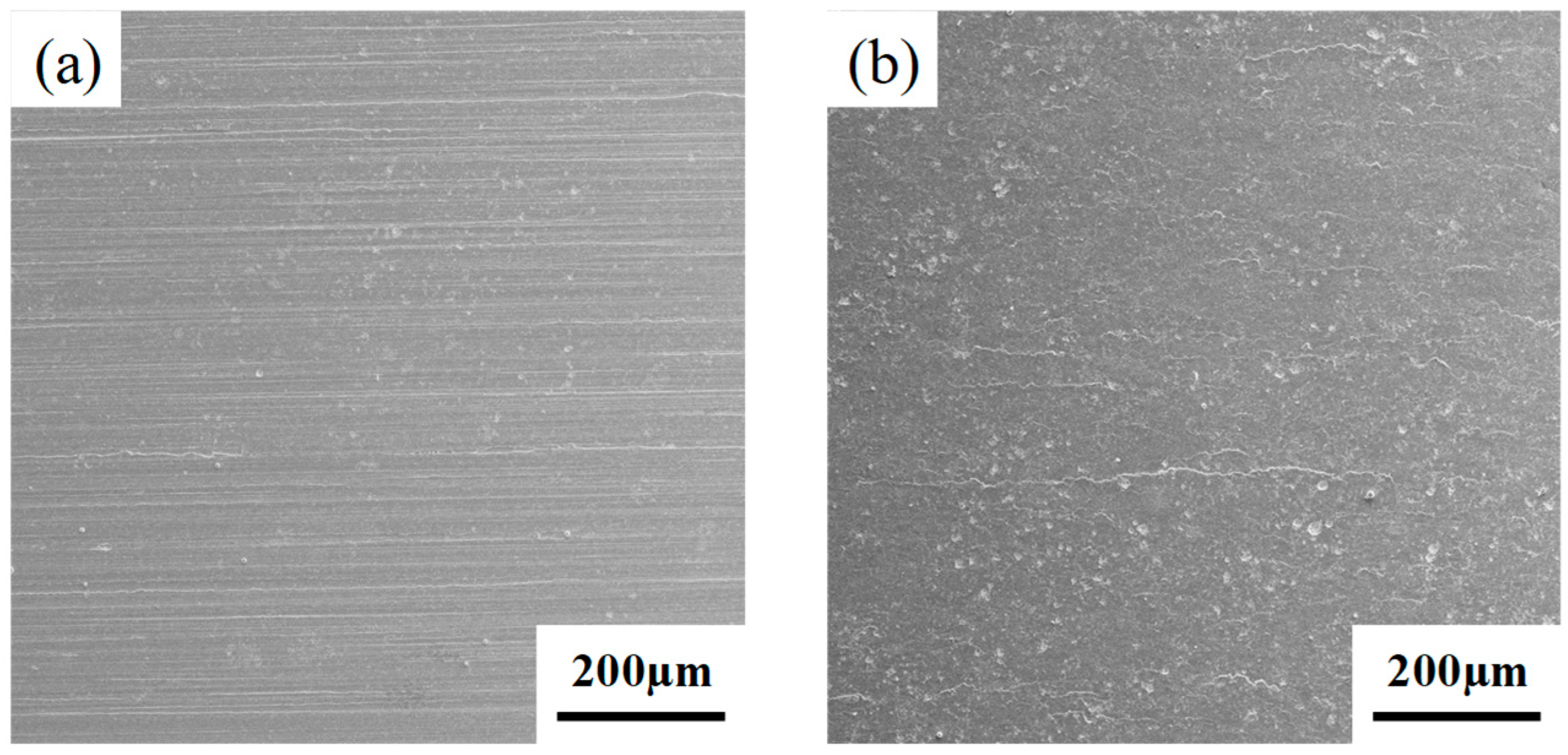
The evolution of surface morphology in specimens before and after D-SMRT is illustrated in Figure 2. The measured surface roughness (Ra) values are 8.181 µm and 4.358 µm for the CG and GS specimens, respectively. The CG specimen exhibits unidirectional parallel scratches on its surface (Figure 2a), characteristic of the grinding process. In contrast, the GS specimen shows a significantly altered surface morphology (Figure 2b), where the original grinding-induced parallel scratches were eliminated, replaced by a flat surface with scattered microcracks and small pits. This observation aligns with the findings reported by Wang et al. [32]. Under the cyclic action of the rolling tool, the surface material undergoes plastic flow, causing the peaks to fill the valleys and flattening sharp asperities. However, due to the limited cold plastic deformation capability of 42CrMo steel, surface material damage (such as microcracks or spalling pits) was observed after the accumulated plastic deformation exceeded a critical threshold.

3.2. Microstructural Analysis

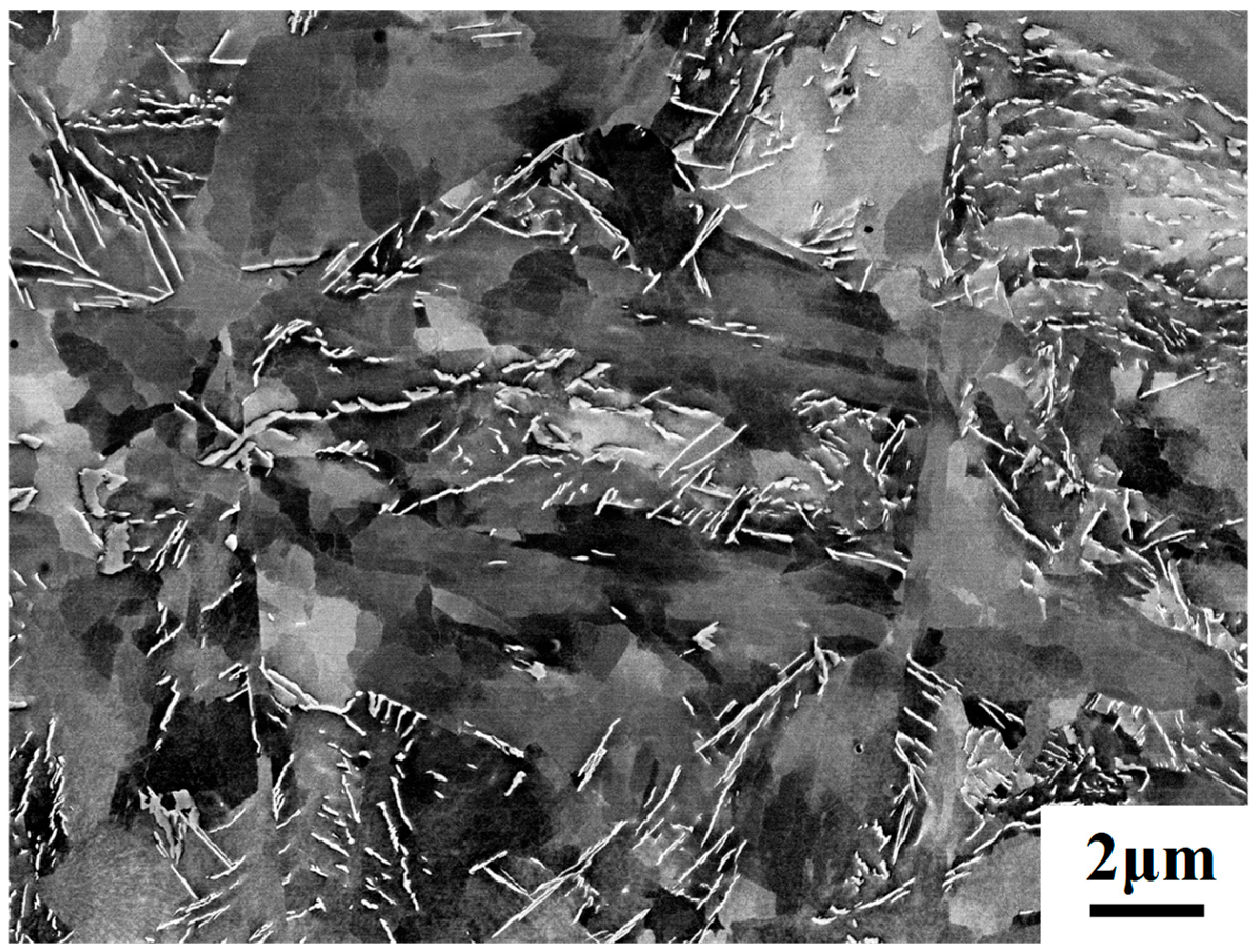
The microstructure of the CG specimen of 42CrMo steel is shown in Figure 3. The original microstructure consists of degenerated pearlite and ferrite. For grains initially in the pearlitic state, the cementite lamellae are no longer arranged in parallel after degeneration, manifesting as irregularly distributed white fine lines of varying lengths. Due to the fragmentation of cementite, the previously separated ferrite is manifested as a continuous piece. The ferrite grains exhibit uniform contrast indicating a lower dislocation density after annealing.
The gradient-structured surface layer of 42CrMo steel fabricated by D-SMRT exhibits distinct microstructural evolution characteristics as revealed in Figure 4. Cross-sectional analysis demonstrates a 350 µm-thick gradient layer with progressive refinement of microstructural dimensions from the substrate to the treated surface. While the low-magnification micrograph (Figure 4a) provides limited structural resolution, higher magnification observation (×5000) enables detailed characterization of deformation-induced microstructural alterations. In the subsurface region (~350 µm below the surface), the morphology and distribution of cementite retain characteristics comparable to the original coarse-grained matrix, as shown in Figure 4b. The heterogeneous contrast within ferrite grains can be observed, which suggests non-uniform multiplication of dislocations during plastic deformation. With decreasing depth to ~150 µm (Figure 4c), strain gradient intensification induces rearrangement of fragmented carbides into banded configurations, accompanied by enhanced contrast variation in ferrite grains indicative of localized strain accumulation. Notably, cementite alignment develops specific orientation dependence near the extreme surface, exhibiting preferential parallel arrangement relative to the treated surface, and this surface-proximal ordered distribution reverts to a disordered distribution in the 5–30 µm range, as shown in Figure 4d. The density of cementite is significantly higher in the near-surface region than in the inner region. Such depth-dependent structural evolution correlates strongly with the gradient distributions of plastic strain and plastic strain rate inherent to D-SMRT.

3.3. Hardness

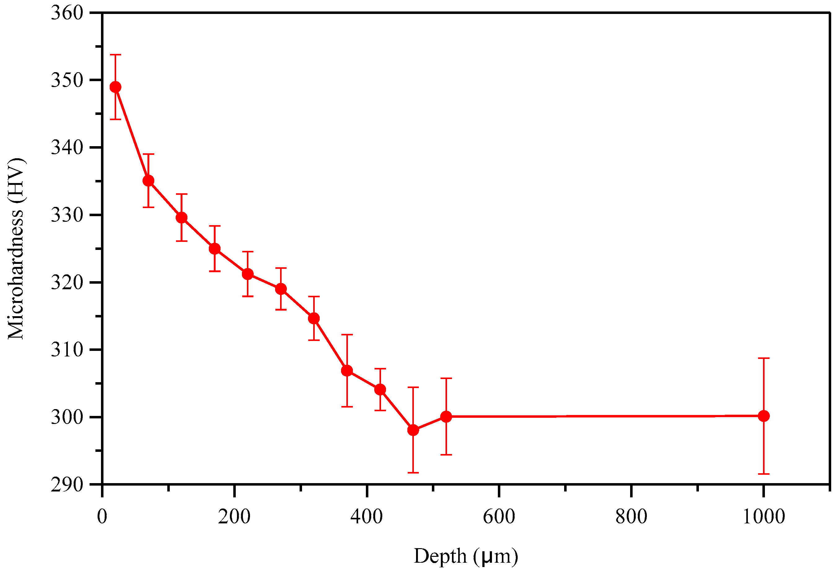
The hardness of a material serves as a crucial indicator correlating with its wear resistance. Figure 5 presents the relationship between the cross-sectional microhardness and depth from the surface of the GS specimen. At the near-surface region (depth of ~20 μm), the hardness is 348 HV. A gradual decline in microhardness can be observed with increasing depth. At a depth of ~370 μm, the hardness reaches 306 HV, equivalent to that of the CG specimen. Compared to the CG specimen, the GS specimen exhibits a 13.73% enhancement in near-surface microhardness. This gradient distribution of microhardness can be attributed to the corresponding gradient microstructure of GS specimen [33].

3.4. Tribological Performance Analysis

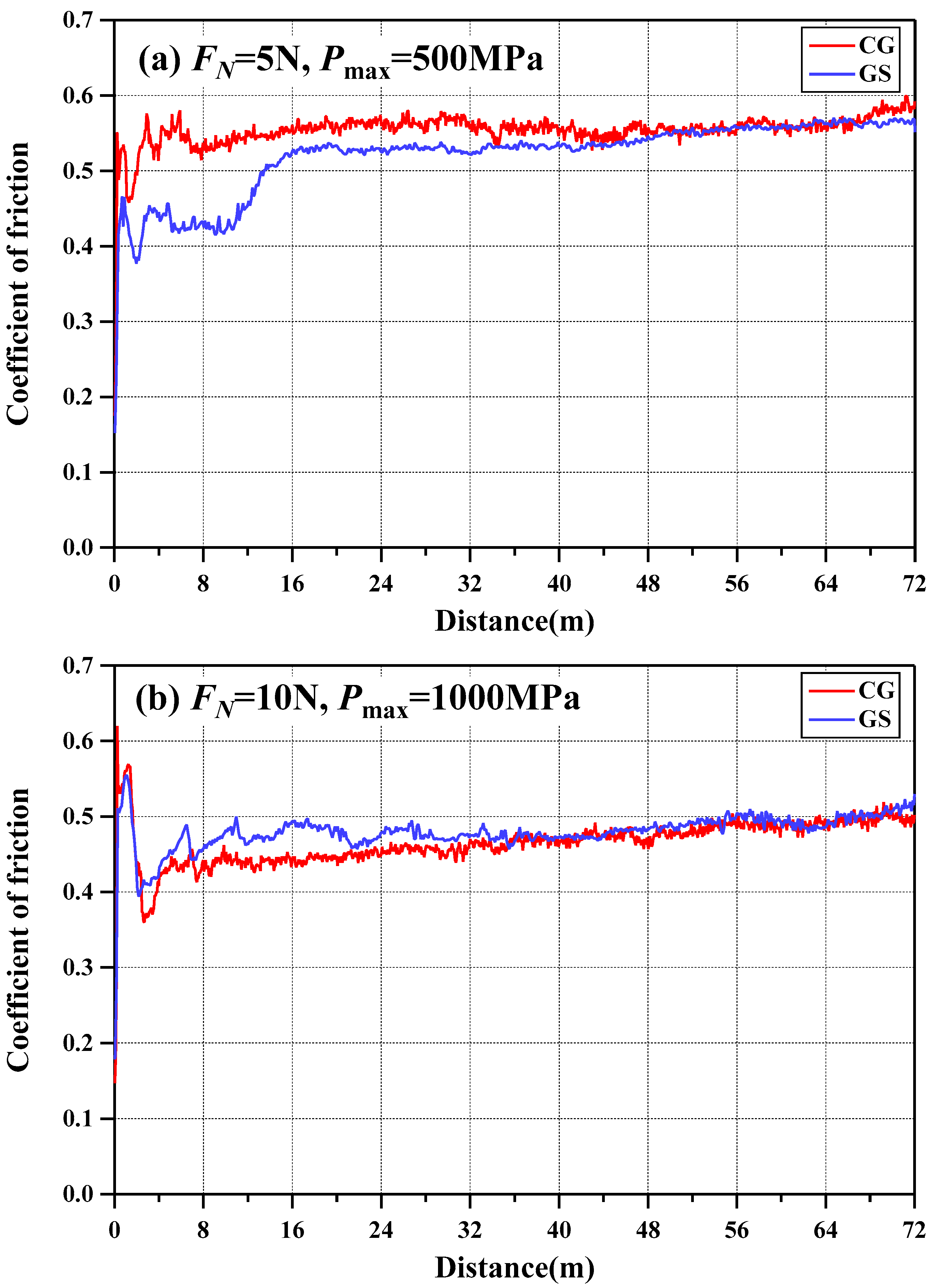
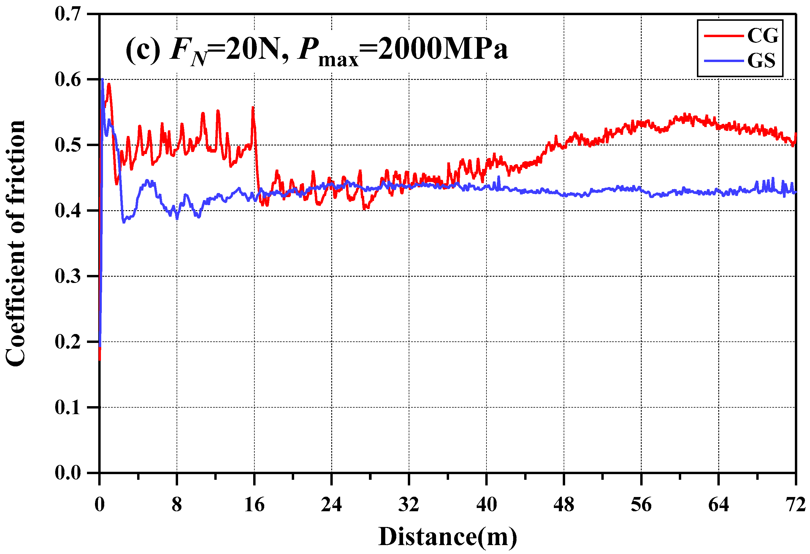
Figure 6 shows the relationship between the coefficient of friction (COF) and sliding distance for CG and GS specimens under different normal loads. Under a 5 N normal load (Figure 6a), the COF of the CG specimen rapidly increased to 0.58 in the initial stage and stabilized at approximately 0.56 after 8 m of sliding. In contrast, the COF of the GS specimen first rose sharply to around 0.42, followed by a secondary increase before reaching a steady-state value of 0.54 after a total sliding distance of 16 m. When the normal load was increased to 10 N (Figure 6b), both specimens exhibited similar trends in COF evolution, characterized by an initial rise, followed by a decline, and then a subsequent increase, ultimately stabilizing near 0.47. At a higher normal load of 20 N (Figure 6c), the CG specimen displayed significant initial fluctuations around 0.5, followed by a decrease to approximately 0.43, a gradual rise to 0.53, and a final decline to 0.5. Meanwhile, the GS specimen stabilized at around 0.43 after initial severe fluctuations.
As shown in Figure 6, all six curves display an initial run-in stage that transitions into a steady state. A notable exception is the CG-20N sample, whose COF increased after 44 m of sliding. Consequently, the steady-state COF was evaluated over different sliding intervals: 17–44 m for CG-20N and 16–72 m for all other conditions. The results, presented in Figure 7, reveal a clear trend of decreasing steady-state COF with increasing maximum Hertzian pressure for both CG and GS specimens.
The observed running-in behavior, featuring characteristic COF peaks, can be attributed to initial surface roughness effects. During early sliding, limited asperity contacts resulted in elevated contact pressures, while mechanical interlocking between surface irregularities requires substantial shear forces to initiate motion—collectively producing the initial friction maximum. The difference in running-in duration between specimens correlates with their initial surface topography: the smoother CG surfaces facilitated earlier transition to steady-state wear, particularly evident at 5 N and 10 N loading conditions.
Figure 8 presents the wear scar morphologies of both CG and GS specimens. The average width of wear scars increased with normal load, and the scars of CG specimens are slightly wider than those of GS specimens under identical loading conditions. Notably, the CG specimen under 10 N loading displayed an asymmetric wear scar profile (wider at one end), while the other five test conditions produced nearly parallel scar edges. This non-uniform wear pattern in CG specimens may be attributed to surface irregularities or slight angular misalignment, which induced uneven load distribution and consequently led to heterogeneous plastic deformation across the contact surface. The variation in scar width suggests localized differences in contact area or frictional repetition susceptibility. This observation aligns with previous findings by Zong [34], who associated such wear scar inhomogeneity with dynamic instabilities during the sliding process. Our results imply that enhancing surface hardness and improving geometric uniformity could effectively mitigate wear scar asymmetry.
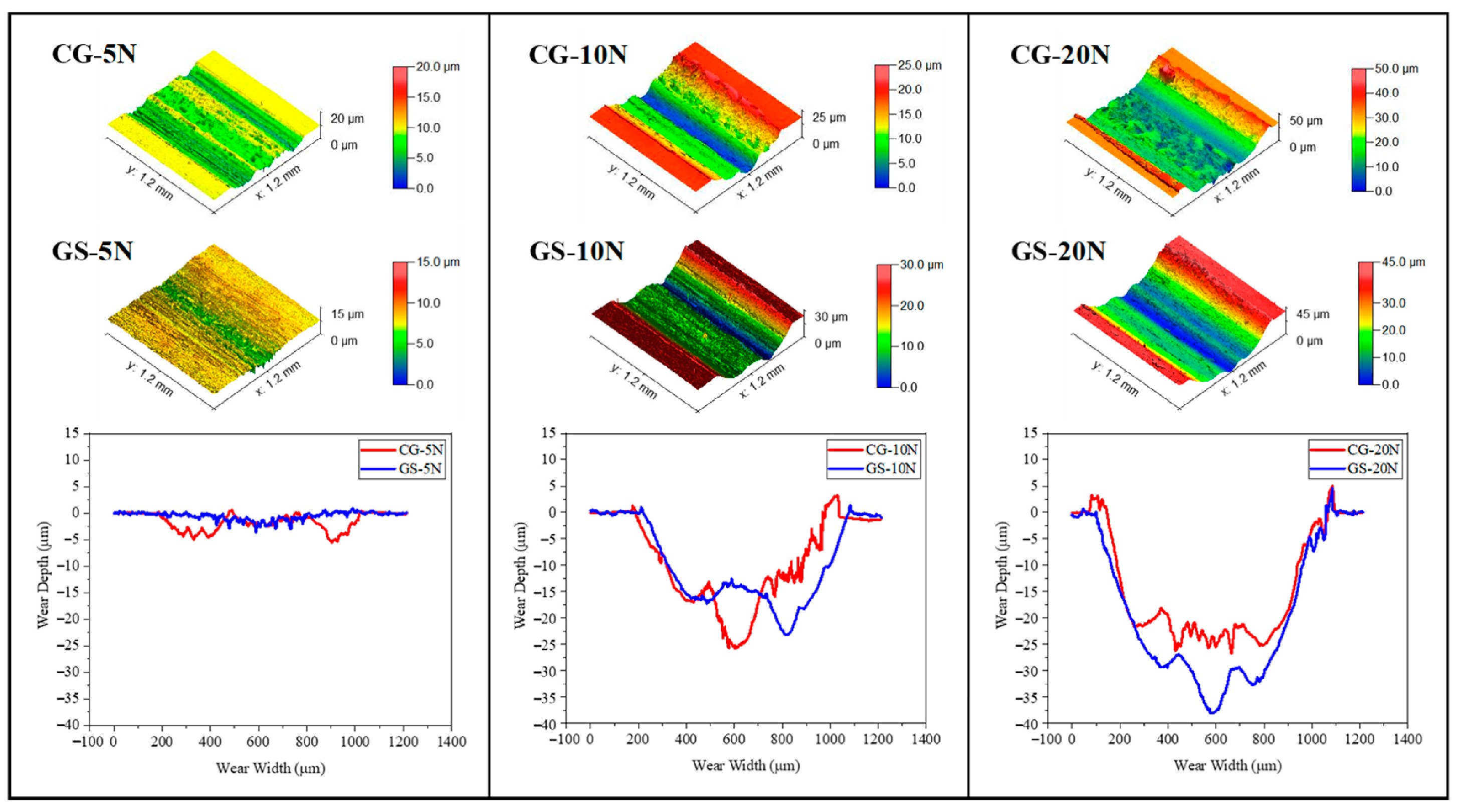
Figure 9 presents the 3D morphology of wear tracks and their corresponding 2D cross-sectional profiles for both specimens. The wear track depth exhibited a load-dependent increase, with the 2D profile curves following an identical trend. Distinct material pile-ups were observed along the track edges of both specimens, indicative of abrasive cutting mechanisms. The GS specimens demonstrated lower pile-up heights compared to their CG counterparts. The depth of wear track of GS specimen was greater than that of CG specimen at a normal load of 20 N, while the opposite trend was observed for the other two normal loads.
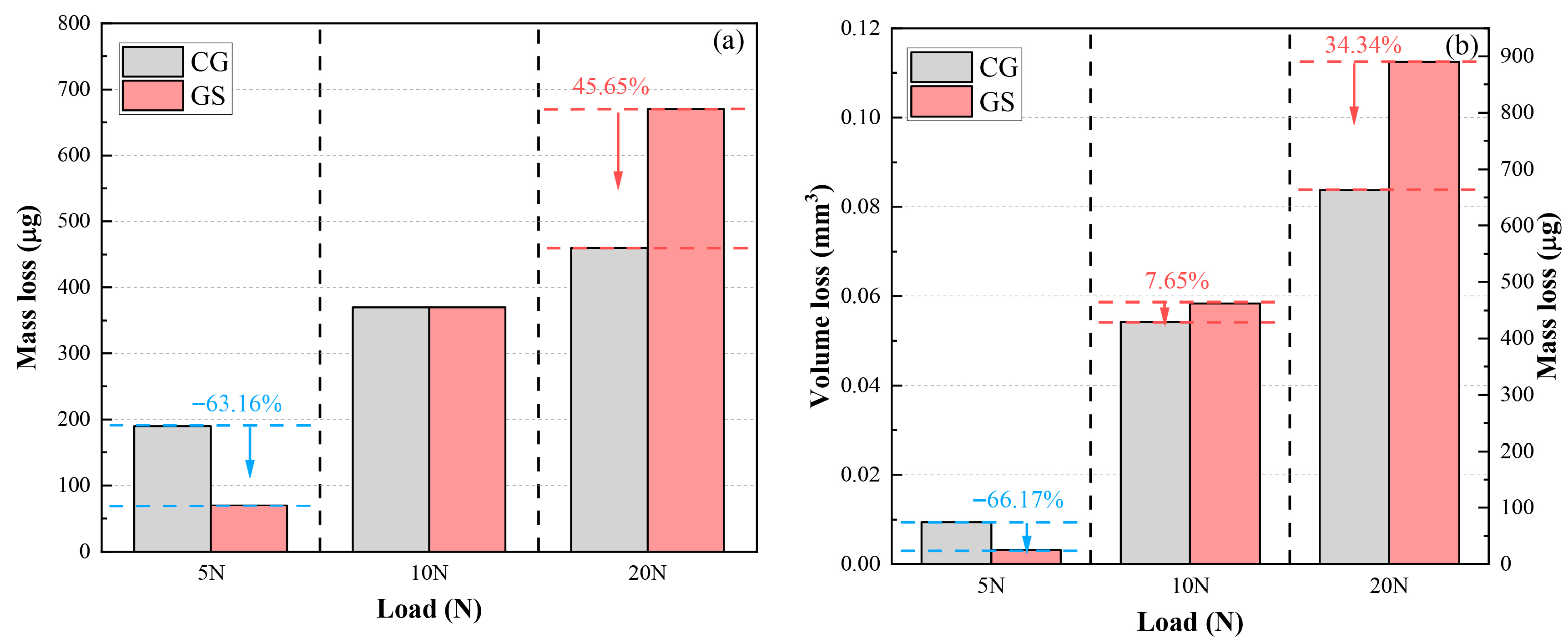
Figure 10a shows the wear mass loss determined by weighting method. Under a normal load of 5 N, the GS specimen exhibited a 63.16% reduction in mass loss compared to the CG specimen. At 10 N, both specimens demonstrated equivalent mass loss, which indicates that their wear resistances are very similar but not necessarily statistically identical. However, the GS specimen showed a 45.65% increase in mass loss relative to the CG specimen under a normal load of 20 N. The mass loss for CG and GS specimens increased with applied normal load. The reduced wear-induced mass loss under lower load conditions (≤10 N) of GS specimens were due to the enhanced hardness induced by D-SMRT. The wear loss of volume and mass determined by wear track morphology are also presented in Figure 10b. It is obvious that the wear mass values determined by both methods correlate well in trend despite differences in their absolute magnitudes.
Based on the wear volume, the wear coefficients were determined by Archard’s wear law:
K = H V F N L
where K is the dimensionless Archard wear coefficient, V is the total wear volume, FN is the applied normal load, L is the total sliding distance, and H is the Vickers hardness of the tested specimen. The total sliding distance of each specimen is 72 m. The surface Vickers hardness of CG specimen is 306 HV, and that of GS specimen is 348 HV. The calculated results of dimensionless Archard wear coefficient are given in Table 2. At the lower normal load (5 N), the CG specimen exhibited a higher wear coefficient than the GS specimen. However, at the higher loads (10 N and 20 N), the converse was true.

4. Discussion

4.1. Surface Analysis of Steel Balls

Figure 11 presents the wear scar morphology of GCr15 steel balls (with a hardness of 63 HRC, equivalent to 772 HV) sliding against CG and GS specimens. The hardness disparity between the steel balls and specimens resulted in less pronounced wear on the balls. Under a 5 N load, extensive scratching was observed on the ball surfaces, indicative of a predominant abrasive wear mechanism. At 10 N, adhered transfer layers appeared on balls paired with both specimens. When the normal load increased to 20 N, the CG specimen’s counter ball exhibited enlarged white spalling zones, whereas the GS specimen’s ball showed increased adhesive deposits.
Table 3 summarizes the EDS point analysis of selected regions on the balls. According to GB/T 18254-2016 standard [35], the GCr15 requires ≤0.0015 wt.% O, 0.95–1.05 wt.% C, and typically <0.1 wt.% Mo. Notably, Regions 4, 8, and 10 exhibited oxygen contents significantly exceeding the standard limit, confirming oxidative wear. Elevated carbon levels in Regions 3, 6, and 9 likely originated from carbide formation via reactions between C and alloying elements (Cr/Mn) during wear [36]. Moreover, anomalous Mo concentrations in Regions 6 and 10 surpassed the GCr15 specification, providing direct evidence of material transfer from specimens, which is a hallmark of adhesive wear mechanisms.

4.2. Analysis of Wear Mechanisms

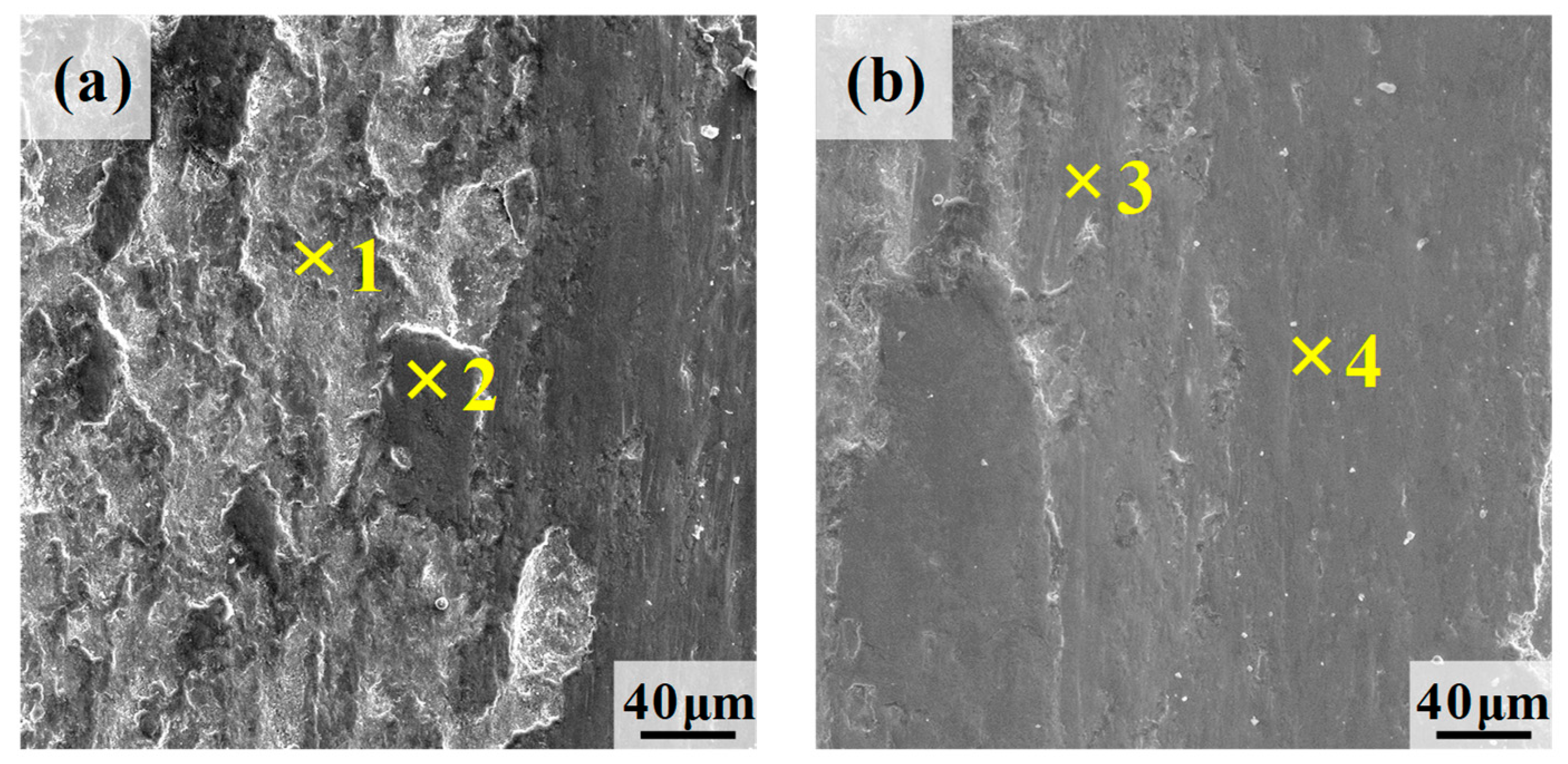
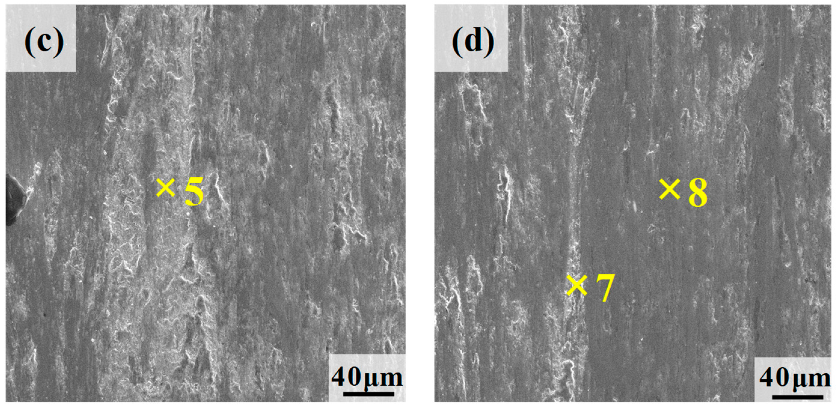
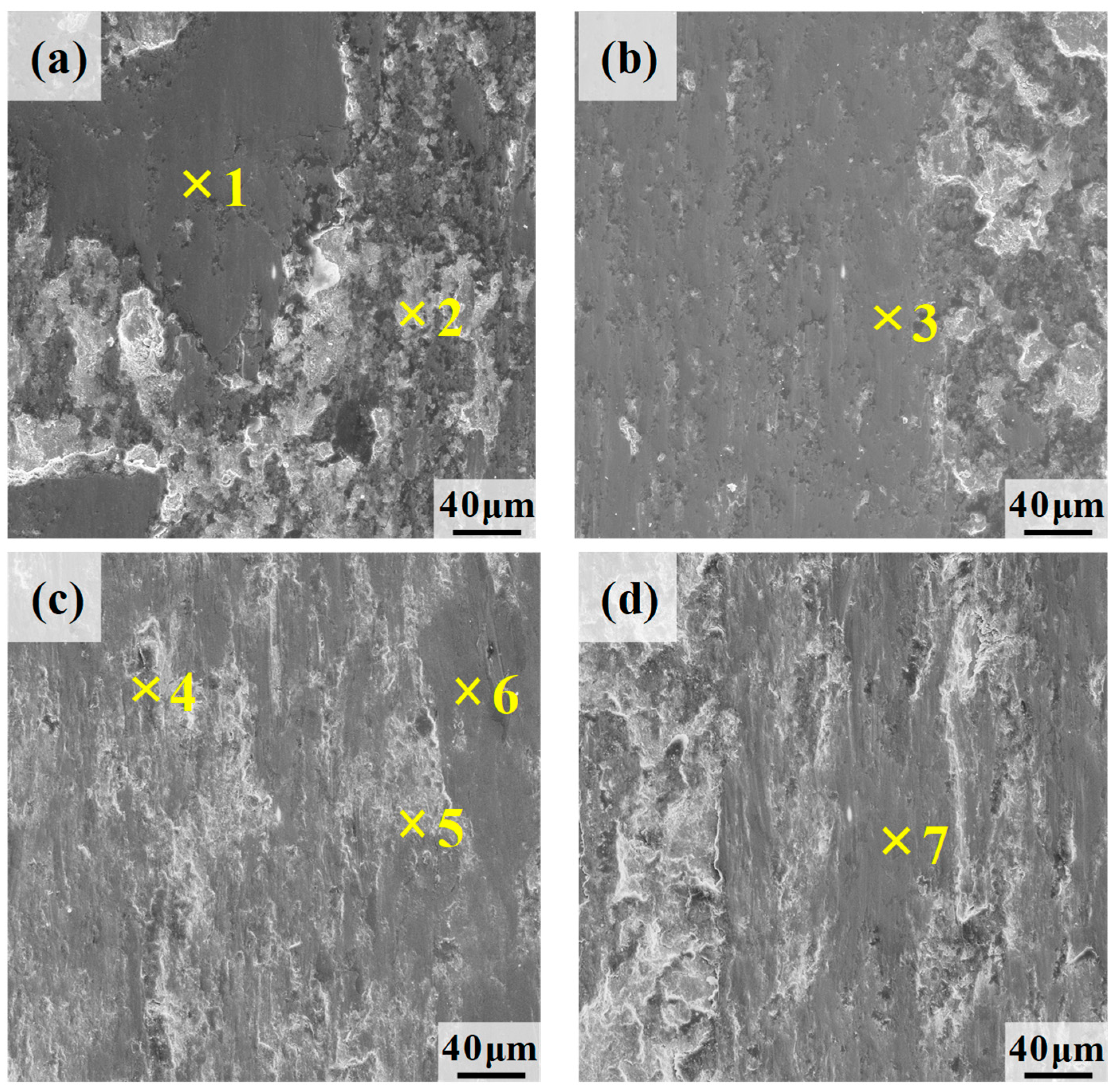
Figure 12 presents the SEM morphology of wear tracks on the specimens under a 5 N normal load. As shown in Figure 12a,c, both CG and GS specimens exhibited minor spalling pits and delamination structures on their wear track surfaces. In contrast, distinct plowing grooves and furrows were observed along the track edges (Figure 12b,d). During reciprocating sliding, the high-hardness GCr15 steel ball imposed significant cyclic contact stresses on the specimen surfaces, inducing fatigue-induced material removal and generating wear debris that participated in the friction process as third-body particles [28,37]. Under combined normal and tangential loading, some debris or hard asperities from the steel ball became embedded into the specimen surface, forming plowing grooves along the track edges. Table 4 summarizes the EDS point analysis of different regions within the wear tracks under a 5 N normal load. The dark gray agglomerates on the track surfaces showed higher oxygen content compared to the white spalling zones and plowing regions, confirming tribo-oxidation during friction [17,25]. The sliding motion promoted reactions between the specimen surface and atmospheric oxygen, generating oxide films. However, the oxidation rate was lower than the material removal rate, causing continuous oxide film delamination and resulting in pit and delamination formation. These observations demonstrate that both specimens experienced combined abrasive and oxidative wear mechanisms.
Under increased normal load (10 N), significant morphological differences emerged between the wear tracks of CG and GS specimens. As illustrated in Figure 13a,b, the CG specimen exhibited pronounced asymmetric wear characteristics. One side of the track showed extensive delamination and spalling, while the opposing side displayed relatively smoother surfaces dominated by plowing grooves and pits. EDS analysis revealed elevated oxygen content in Regions 2 and 4, suggesting active oxidation processes. These observations indicate that oxidative wear and abrasive wear predominated in the CG specimen, with secondary fatigue wear contribution. In contrast, the GS specimen demonstrated fundamentally different wear behavior (Figure 13c,d). Its surface exhibited continuous white zones characterized by flake-like delamination, accompanied by substantial adhesive debris accumulation and plowing structures. Table 5 summarizes the EDS point analysis of different regions within the wear tracks under a 10 N normal load. EDS confirmed the presence of oxides within these wear tracks. The elevated contact pressure promoted shear fracture at asperity junctions, generating abundant wear debris [38]. Under normal load, these free debris particles became embedded in both surfaces of specimen and steel ball, initiating adhesive wear mechanisms. This evidence establishes adhesive wear as the dominant mechanism for the GS specimen at 10 N, with concurrent oxidative and abrasive wear components.
Under a normal load of 20 N, the CG specimen exhibited crack propagation accompanied by intensified material spalling, with increased pit density and delamination structures (Figure 14a,b). The elevated cyclic stresses promoted crack initiation at steel defects, where subsequent propagation to critical dimensions caused surface material removal through shear-induced delamination [39,40]. Table 6 summarizes the EDS point analysis of different regions within the wear tracks under a 20 N normal load. EDS analysis revealed minimal oxygen content across examined regions, confirming the predominance of abrasive and fatigue wear mechanisms. The GS specimen demonstrated expanded spalling regions and reduced surface oxygen content at 20 N compared to 10 N loading (Figure 14c,d). The enhanced normal load promoted greater conversion of mechanical energy into frictional heat at the contact interface. This thermal input caused simultaneous softening of both the substrate material and surface oxide films, leading to pronounced plastic deformation of the mating surfaces. During this process, detached wear debris became re-embedded into the surfaces under combined thermal and mechanical loading. The refined near-surface microstructure of the GS specimen [41,42,43] provided improved oxidation resistance at elevated temperatures, resulting in the formation of thinner oxide films. Consequently, the GS specimen’s wear mechanism transitioned to primarily adhesive wear accompanied by substantial plastic deformation.
The divergent tribological behavior of CG and GS specimens stems from intrinsic differences in surface geometry, microstructure, and physicochemical properties. Geometrically, CG specimens possessed a smoother surface than GS specimens. During initial sliding, this led to fewer but more highly stressed asperity contacts in GS specimens, inducing severe asperity collapse, compression, and localized plastic deformation [44]. With prolonged sliding, work hardening occurred in both materials, causing their inherent microstructural characteristics and hardness to dominate wear behavior [10,45]. The superior wear resistance of the GS specimen may stem from its gradient-structured surface layer, which, as reported in [15], enhances wear performance by a mechanism that suppresses strain localization and inhibits crack initiation and propagation. However, once the work-hardened layers were worn away, both materials displayed similar wear performance. Consistent with the Archard relationship [46], the enhanced bulk hardness of GS specimens directly contributed to their reduced material loss, as wear resistance is inversely proportional to hardness.
Under a 20 N normal load, the nascent oxide films fail to counteract severe plastic deformation caused by high contact stresses, leading to accelerated material degradation. Notably, despite their lower surface hardness, CG specimens demonstrated superior toughness and enhanced work hardening capacity under reciprocating sliding conditions, ultimately leading to reduced mass loss compared to GS specimens. As shown in Figure 2b, the surface of GS specimen contains many micro-defects, including deep pits and microcracks. These surface imperfections acted as stress concentrators under high contact pressures, promoting crack initiation and propagation that synergistically exacerbate material damage. The higher wear volume of GS specimens under high-load conditions arises from two key factors: (1) limited work-hardening capacity and (2) inherent susceptibility to surface defects. This observation highlights that in severe sliding wear regimes, surface integrity and strain-hardening capability become decisive factors. Under such extreme contact conditions, conventional protective mechanisms (e.g., oxide films) are progressively overridden by mechanically dominated damage processes.

5. Conclusions

This study systematically examined the influence of a normal load and gradient-structured surface layer on the tribological performance of 42CrMo steel. The key findings are summarized as follows:
1.
The frictional behavior of the specimens exhibited distinct load-dependent characteristics. The coefficient of friction (COF) of the CG specimens initially decreased and then increased with rising normal load, whereas that of the GS specimens decreased continuously. This trend can be attributed to the progressive formation of protective oxide films at the sliding interface due to enhanced oxidative reactions.
2.
A clear transition in wear mechanisms was observed with increasing load. The CG specimens transitioned from oxidative/abrasive wear at lower loads (5 and 10 N) to abrasive/fatigue wear at 20 N. In contrast, the GS specimens underwent a more progressive shift: from oxidative/abrasive wear at 5 N to adhesive/abrasive wear at 10 N and finally to adhesive wear accompanied by significant plastic deformation at 20 N.
3.
The wear resistance of the GS specimen degraded with increasing load. It showed 63.16% less mass loss than the CG specimen at 5 N, but 45.65% more at 20 N. This performance reversal, confirmed by the Archard wear coefficients, demonstrates the limitation of the gradient structure under high load.

Author Contributions

Conceptualization, H.Z. and X.W.; methodology, H.Z.; software, L.D.; validation, B.Q. and Z.L.; formal analysis, B.Q.; investigation, H.Z.; data curation, Y.C.; writing—original draft preparation, H.Z. and B.Q.; writing—review and editing, X.W.; funding acquisition, X.W. All authors have read and agreed to the published version of the manuscript.

Funding

The research was funded by the National Natural Science Foundation of China (52175195).

Data Availability Statement

All original data from the study have been fully included in the article and further inquiries can be directed to the corresponding author.

Conflicts of Interest

Authors Huaming Zhang, Li Dong and Zhenling Li were employed by the company CGN Wind Power Co., Ltd. The remaining authors declare that the research was conducted in the absence of any commercial or financial relationships that could be construed as a potential conflict of interest.

References

  1. Wang, Y.P.; Luo, Y.C.; Mo, Q.Y.; Huang, B.; Wang, S.Y.; Mao, X.F.; Zhou, L. Failure analysis and improvement of a 42CrMo crankshaft for a heavy-duty truck. Eng. Fail. Anal. 2023, 153, 107567. [Google Scholar] [CrossRef]
  2. Pan, D.; Zhao, Y.G.; Wang, Y.T.; Xu, X.F.; Yin, P.L.; Chong, X.Y. Formation of ultrafine pearlites in tempered 42CrMo steel induced by electro-pulsing. Mater. Lett. 2019, 251, 73–77. [Google Scholar] [CrossRef]
  3. Zhang, J.T.; Liu, Z.H.; Sun, J.X.; Zhao, H.L.; Shi, Q.Y.; Ma, D.W. Microstructure and mechanical property of electropulsing tempered ultrafine grained 42CrMo steel. Mater. Sci. Eng. A 2020, 782, 139213. [Google Scholar] [CrossRef]
  4. Lv, Y.F.; Xu, P.; Liang, R.; Wang, L.; Pang, C. Corrosion resistance of VC-reinforced Fe-based SMA coatings by laser cladding. Surf. Coat. Technol. 2024, 478, 130457. [Google Scholar] [CrossRef]
  5. Khare, S.; Singh, O.P.; Dora, K.B.; Sasun, C. Spalling investigation of connecting rod. Eng. Fail. Anal. 2012, 19, 77–86. [Google Scholar] [CrossRef]
  6. Wang, K.; Yin, L.Y.; Long, Z.L.; Liang, N.; Zhu, D.D.; Zhang, S.H. Effect of copper-rich precipitations on the adaptive behavior of low carbon martensitic steels during dry sliding wear. Wear 2025, 576–577, 206136. [Google Scholar] [CrossRef]
  7. Zhang, W.; Li, L.; Gao, J.; Liu, J.; Gong, H.; Wang, Q. Theoretical calculation and experimental verification of wear prediction during the tightening process of bolted joint. Tribol. Lett. 2024, 73, 17. [Google Scholar] [CrossRef]
  8. Liu, B.G.; Lu, X.W.; Li, W.; Jin, X.J. Enhanced wear resistance of nanotwinned austenite in higher Si nanostructured bainitic steel. Wear 2018, 398–399, 22–28. [Google Scholar] [CrossRef]
  9. Sun, L.G.; Wu, G.; Wang, Q.; Lu, J. Nanostructural metallic materials: Structures and mechanical properties. Mater. Today 2020, 38, 114–135. [Google Scholar] [CrossRef]
  10. Kumar, K.S.; Van Swygenhoven, H.; Suresh, S. Mechanical behavior of nanocrystalline metals and alloys. Acta Mater. 2003, 51, 5743–5774. [Google Scholar] [CrossRef]
  11. Jeong, D.H.; Erb, U.; Aust, K.T.; Palumbo, G. The relationship between hardness and abrasive wear resistance of electrodeposited nanocrystalline Ni–P coatings. Scripta Mater. 2003, 48, 1067–1072. [Google Scholar] [CrossRef]
  12. Sun, D.Y.; Feng, X.Y.; Zhang, P.; Sun, X.W.; Yang, Z.N.; Long, X.Y.; Zhang, F.C. Effects of two-step austempering processes on the wear resistance and fatigue lifetime of high-carbon nanostructured bainitic steel. J. Mater. Res. Technol. 2024, 30, 4739–4749. [Google Scholar] [CrossRef]
  13. Shah, M.; Bakshi, S.D. Three-body abrasive wear of carbide-free bainite, martensite and bainite-martensite structure of similar hardness. Wear 2018, 402–403, 207–215. [Google Scholar] [CrossRef]
  14. Lu, J.; Wang, K.; Sui, X.M.; Zhang, J.; Wang, H.H.; Qin, Q.M.; Song, Z.F.; Ren, X.L.; Yang, J.X.; Long, F.Q. Rapid synthesis of ultra-wear-resistant nanocrystallite stainless steel via electron beam direct irradiation. Surf. Coat. Technol. 2024, 483, 130714. [Google Scholar] [CrossRef]
  15. Zhou, L.; Liu, G.; Han, Z.; Lu, K. Grain size effect on wear resistance of a nanostructured AISI52100 steel. Scr. Mater 2008, 58, 445–448. [Google Scholar] [CrossRef]
  16. Zhu, Y.T.; Wu, X.L. Heterostructured materials. Prog. Mater. Sci. 2023, 131, 101019. [Google Scholar] [CrossRef]
  17. Cao, Z.Y.; Cui, L.Q.; Luo, S.H.; Su, H.; Pang, Z.C.; Zhao, W.; Zhang, L.Y.; He, W.F.; Liang, X.Q. Superior fretting wear resistance of titanium alloys from stable gradient nanostructures induced by laser shock peening. Int. J. Plast. 2025, 188, 104293. [Google Scholar] [CrossRef]
  18. Duan, C.F.; Qu, S.G.; Sun, P.F.; Li, X.Q. Effect of heating-assisted ultrasonic surface rolling on the microstructure evolution and wear behavior of martensitic steel. Surf. Coat. Technol. 2024, 483, 130759. [Google Scholar] [CrossRef]
  19. Luo, J.S.; Sun, W.T.; Duan, R.X.; Yang, W.Q.; Chan, K.C.; Ren, F.Z.; Yang, X.S. Laser surface treatment-introduced gradient nanostructured TiZrHfTaNb refractory high-entropy alloy with significantly enhanced wear resistance. J. Mater. Sci. Technol. 2022, 110, 43–56. [Google Scholar] [CrossRef]
  20. Lavakumar, B.; Prasad, M.J.N.V.; Phani, P.S.; Wasekar, N.P. Influence of compositional and microstructural gradient on the wear performance of nanocrystalline Ni-W coatings. Wear 2023, 530–531, 205039. [Google Scholar] [CrossRef]
  21. Liu, Y.; Jin, B.; Li, D.; Zeng, X.; Lu, J. Wear behavior of nanocrystalline structured magnesium alloy induced by surface mechanical attrition treatment. Surf. Coat. Technol. 2015, 261, 219–226. [Google Scholar] [CrossRef]
  22. Sun, Y. Sliding wear behaviour of surface mechanical attrition treated AISI 304 stainless steel. Tribol. Int. 2013, 57, 67–75. [Google Scholar] [CrossRef]
  23. Ralls, A.M.; Leong, K.; Liu, S.C.; Wang, X.G.; Jiang, Y.Y.; Menezes, P.L. Unraveling the friction and wear mechanisms of surface nanostructured stainless-steel. Wear 2024, 538–539, 205185. [Google Scholar] [CrossRef]
  24. Li, M.Y.; Dang, X.F.; Ning, L.Z.; Liu, D.R.; Geng, Y.F.; Cheng, F.Y.; Dong, J.Y.; Liang, R.Y.; Tian, Z.; Zhou, G.N.; et al. Post-processing of laser-directed energy deposited IN718 superalloys through combined heat treatment and shot peening: Microstructural evolution and wear resistance enhancement. Surf. Coat. Technol. 2025, 509, 132209. [Google Scholar] [CrossRef]
  25. Hu, H.B.; Tang, G.B.; Cheng, Z.T.; Pan, Y.T.; Huang, Z.B.; Ding, W.F.; Liang, Z.W. Co-Cr3C2 coating incorporating grain refinement and dislocation density gradient to enhance wear resistance of 24CrNiMo steel. Wear 2025, 546, 205752. [Google Scholar] [CrossRef]
  26. Pape, F.; Maiss, O.; Denkena, B.; Poll, G. Enhancement of roller bearing fatigue life by innovative production processes, Ind. Lubr. Tribol. 2019, 71, 1003–1006. [Google Scholar] [CrossRef]
  27. Zou, Y.; Li, J.K.; Liu, X.; He, T.T.; Lu, J.S.; Li, D.L.; Li, Y. Effect of multiple ultrasonic nanocrystal surface modification on surface integrity and wear property of DZ2 axle steel. Surf. Coat. Technol. 2021, 412, 127012. [Google Scholar] [CrossRef]
  28. Wang, P.F.; Han, Z. Friction and wear behaviors of a gradient nano-grained AISI 316L stainless steel under dry and oil-lubricated conditions. J. Mater. Sci. Technol. 2018, 34, 1835–1842. [Google Scholar] [CrossRef]
  29. Wang, Y.J.; Jia, Z.; Ji, J.J.; Cheng, Q.Q.; Chan, L.; Lu, X.Z.; Lai, C.P.; Liu, D.X. Surface mechanical rolling treatment-introduced gradient nanostructured Inconel 625 alloy with enhanced high-temperature wear resistance. Tribol. Int. 2025, 201, 110187. [Google Scholar] [CrossRef]
  30. Wang, C.; Liu, X.; Hu, X.Y.; Fei, S.H.; Li, B.K.; Deng, H.S.; Shen, G.; Wang, X.G. Gradient-structured 1060 aluminum by air pressure-driven surface mechanical rolling treatment and its effects on the friction performance. J. Manuf. Process. 2023, 108, 804–819. [Google Scholar] [CrossRef]
  31. Tang, Y.H.; Ji, P.F.; Li, B.; Zhang, G.F.; Ma, W.; Wang, F.; Zhang, X.Y.; Ma, M.Z.; Liu, R.P. Effect of loading on microstructure and friction and wear behavior of an austenite lightweight steel. Tribol. Int. 2023, 177, 108006. [Google Scholar] [CrossRef]
  32. Wang, H.B.; Song, G.L.; Tang, G.Y. Enhanced surface properties of austenitic stainless steel by electropulsing-assisted ultrasonic surface rolling process. Surf. Coat. Technol. 2015, 282, 149–154. [Google Scholar] [CrossRef]
  33. Yang, H.W.; Zhang, Z.C.; Shu, J.; Han, Y. Gradient nanostructure, enhanced surface integrity and fatigue resistance of Ti-6Al-7Nb alloy processed by surface mechanical attrition treatment. J. Mater. Sci. Technol. 2024, 188, 252–269. [Google Scholar] [CrossRef]
  34. Zong, H.J.; Kang, N.; Mansori, M.E. Impact of applied loads on wear mechanisms in H13 steel at various preheating temperatures during laser powder bed fusion additive manufacturing. Wear 2024, 556–557, 205538. [Google Scholar] [CrossRef]
  35. GB/T 18254-2016; High-Carbon Chromium Bearing Steel. Standardization Administration of the People’s Republic of China: Beijing, China, 2016.
  36. Li, J.; Yan, H.Z.; Li, S.B.; Lei, M.T. Microstructure and wear behavior of arc-shaped 40CrNiMo steel after laser hardening. J. Mater. Res. Technol. 2023, 24, 5743–5754. [Google Scholar] [CrossRef]
  37. Derelizade, K.; Rincon, A.; Venturi, F.; Wellman, R.G.; Kholobystov, A.; Hussain, T. High temperature (900 °C) sliding wear of CrNiAlCY coatings deposited by high velocity oxy fuel thermal spray. Surf. Coat. Technol. 2022, 432, 128063. [Google Scholar] [CrossRef]
  38. Wei, M.X.; Wang, S.Q.; Wang, L.; Cui, X.H.; Chen, K.M. Effect of tempering conditions on wear resistance in various wear mechanisms of H13 steel. Tribol. Int. 2011, 44, 898–905. [Google Scholar] [CrossRef]
  39. Syniuta, W.D.; Corrow, C.J. A scanning electron microscopy fractographic study of rolling-contact fatigue. Wear 1970, 15, 187–199. [Google Scholar] [CrossRef]
  40. Suh, N.P. The delamination theory of wear. Wear 1973, 25, 111–124. [Google Scholar] [CrossRef]
  41. Wei, L.L.; Wang, Y.G.; Misra, R.D.K.; Chen, J. Understanding the high-temperature oxidation resistance of heat-resistant austenitic stainless steel with gradient nanostructure. Corros. Sci. 2024, 231, 111966. [Google Scholar] [CrossRef]
  42. Singh, D.; Cemin, F.; Jimenez, M.J.M.; Antunes, V.; Alvarez, F.; Orlov, D.; Figueroa, C.A.; Hosmani, S.S. High-temperature oxidation behaviour of nanostructure surface layered austenitic stainless steel. Appl. Surf. Sci. 2022, 581, 152437. [Google Scholar] [CrossRef]
  43. Rai, A.K.; Biswal, R.; Gupta, R.K.; Rai, S.K.; Singh, R.; Goutam, U.K.; Ranganathan, K.; Ganesh, P.; Kaul, R.; Bindra, K.S. Enhancement of oxidation resistance of modified P91 grade ferritic-martensitic steel by surface modification using laser shock peening. Appl. Surf. Sci. 2019, 495, 143611. [Google Scholar] [CrossRef]
  44. Menezes, P.L.; Kishore; Kailas, S.V. Influence of roughness parameters and surface texture on friction during sliding of pure lead over 080 M40 steel. Int. J. Adv. Manuf. Technol. 2009, 43, 731–743. [Google Scholar] [CrossRef]
  45. Jiang, J.; Stack, M.M. Modelling sliding wear: From dry to wet environments. Wear 2006, 261, 954–965. [Google Scholar] [CrossRef]
  46. Archard, J.F. Contact and rubbing of flat surfaces. J. Appl. Phys. 1953, 24, 981–988. [Google Scholar] [CrossRef]
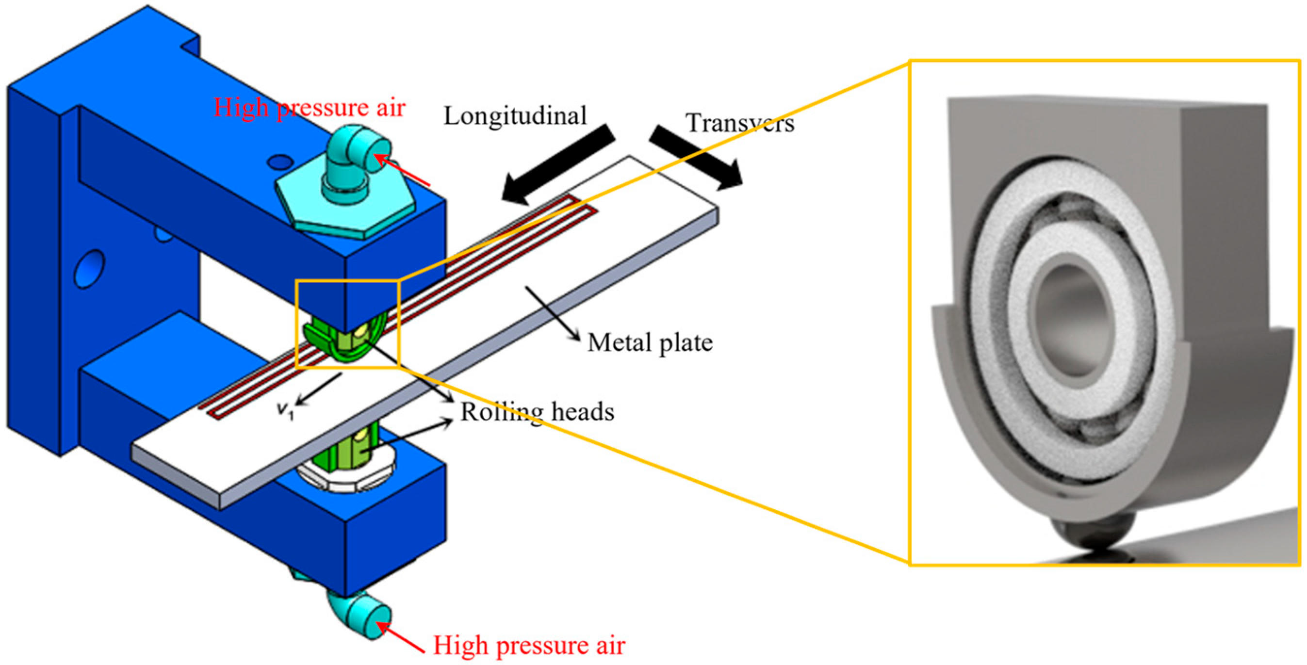
Figure 1. An illustration of the pneumatically driven adaptive D-SMRT equipment.
Lubricants 13 00448 g001
Figure 2. Surface morphology of (a) CG and (b) GS specimens.
Lubricants 13 00448 g002
Figure 3. Cross-sectional SEM observations of the microstructures of CG specimen.
Lubricants 13 00448 g003
Figure 4. Cross-sectional SEM observations of the deformation microstructures at depths: (a) 0–400 μm, (b) ~350 μm, (c) ~150 μm, and (d) 0–30 μm.
Lubricants 13 00448 g004
Figure 5. The cross-sectional microhardness profile of GS specimen versus depth.
Lubricants 13 00448 g005
Figure 6. Evolution of COF versus sliding distance for CG and GS specimens under normal loads of (a) 5 N, (b) 10 N, and (c) 20 N.
Lubricants 13 00448 g006aLubricants 13 00448 g006b
Figure 7. Steady-state COFs of CG and GS specimens under different maximum Hertzian pressures.
Lubricants 13 00448 g007
Figure 8. Overview of reciprocating wear tracks on the surfaces of CG and GS specimens.
Lubricants 13 00448 g008
Figure 9. 3D wear track morphology and cross-sectional profiles of CG and GS specimens under three normal loads.
Lubricants 13 00448 g009
Figure 10. Wear loss of CG and GS specimens under varying normal loads: (a) mass loss determined by weighting method; (b) volume and mass loss determined by wear track morphology.
Lubricants 13 00448 g010
Figure 11. SEM images and EDS point analysis locations on the surfaces of counter balls.
Lubricants 13 00448 g011
Figure 12. SEM characterization of wear tracks under a 5 N normal load: (a,b) CG specimen and (c,d) GS specimen.
Lubricants 13 00448 g012
Figure 13. SEM characterization of wear tracks under a 10 N normal load: (a,b) CG specimen and (c,d) GS specimen.
Lubricants 13 00448 g013aLubricants 13 00448 g013b
Figure 14. SEM characterization of wear tracks under a 20 N normal load: (a,b) CG specimen and (c,d) GS specimen.
Lubricants 13 00448 g014
Table 1. Chemical compositions of 42CrMo steel (wt.%).
CrSiMnNiMoPCFe
1.1500.2740.5700.0310.7190.0170.420Balance
Table 2. Dimensionless Archard wear coefficient.
Case5 N10 N20 N
CG7.87 ∗ 10−52.26 ∗ 10−41.74 ∗ 10−4
GS3.03 ∗ 10−52.77 ∗ 10−42.66 ∗ 10−4
Table 3. EDS results of different surface regions on counter balls (wt.%).
CasePointFeOCCrMnMo
CG-5N194.790.524.080.61--
GS-5N293.190.284.841.280.41-
CG-10N392.360.346.260.830.21-
489.802.375.671.330.580.26
GS-10N594.880.393.391.040.170.13
693.630.783.700.970.360.57
CG-20N793.550.355.290.81--
885.231.5811.921.010.25-
GS-20N993.491.803.201.130.180.19
1081.0014.192.781.120.430.48
Table 4. EDS results of different wear scar regions of both specimens under a 5 N normal load (wt.%).
CasePointFeOCCrMnMo
CG-5N184.560.6313.100.920.430.36
265.3727.545.621.130.250.09
361.9331.395.530.900.25-
489.360.568.690.980.45-
GS-5N593.420.534.020.920.910.23
665.9729.683.260.830.140.12
767.5625.595.410.850.310.29
887.310.5010.771.010.41-
Table 5. EDS results of different wear scar regions of both specimens under a 10 N normal load (wt.%).
CasePointFeOCCrMnMo
CG-10N177.090.7520.620.750.270.51
259.7929.369.900.740.20-
466.4026.965.500.620.180.34
587.950.5010.771.010.41-
GS-10N573.8815.469.560.770.33-
680.643.3613.970.990.600.44
777.393.9716.860.850.370.57
883.340.4214.640.880.350.37
Table 6. EDS analysis of different wear scar regions for both specimens under a 20 N normal load (wt.%).
CasePointFeOCCrMnMo
CG-20N188.463.326.551.220.45-
288.692.257.281.080.69-
386.072.679.510.940.510.31
GS-20N479.772.4616.190.640.450.48
580.470.4517.480.750.520.33
681.960.6715.820.820.72-
789.890.488.120.840.430.24
Disclaimer/Publisher’s Note: The statements, opinions and data contained in all publications are solely those of the individual author(s) and contributor(s) and not of MDPI and/or the editor(s). MDPI and/or the editor(s) disclaim responsibility for any injury to people or property resulting from any ideas, methods, instructions or products referred to in the content.