Article

Research on the Correlation between Mechanical Seal Face Vibration and Stationary Ring Dynamic Behavior Characteristics

1
State Key Laboratory of High-End Compressor and System Technology, Beijing University of Chemical Technology, Beijing 100029, China
2
National Oil and Gas Pipeline Network Group Co., Ltd., Beijing 100028, China
*
Author to whom correspondence should be addressed.
Lubricants 2024, 12(9), 316; https://doi.org/10.3390/lubricants12090316
Submission received: 28 July 2024 / Revised: 9 September 2024 / Accepted: 10 September 2024 / Published: 12 September 2024
(This article belongs to the Special Issue Wear Mechanism Identification and State Prediction of Tribo-Parts)

Abstract

:
To address the lack of reliable measurement methods for identifying wear mechanisms and predicting the state of mechanical seal tribo-parts, this study proposes a method for characterizing tribological behavior based on measuring face vibration acceleration. It aims to uncover the source mechanism of mechanical seal face vibration acceleration influenced by tribology and dynamic behavior. This research delves into the dynamic behavior characteristics and vibration acceleration of the mechanical seal stationary ring. We explored the variation pattern of face vibration acceleration root mean square (RMS) with rotation speed, sealing medium pressure, and face surface roughness. The results indicate that under constant medium pressure, an increase in rotation speed leads to a decrease in acceleration RMS and an increase in face temperature. Similarly, under constant rotation speed, an increase in medium pressure results in nonlinear changes in acceleration RMS, forming an “M” shape, along with an increase in face temperature. Furthermore, under conditions of constant medium pressure and rotation speed, an increase in the surface roughness of the rotating ring face corresponds to an increase in acceleration RMS and face temperature. Upon starting the mechanical seal, both acceleration RMS and temperature initially increase before decreasing, a trend consistent with the Stribeck curve.

1. Introduction

The mechanical seal, a pivotal dynamic sealing device, is extensively utilized in power devices like pumps to segregate rotating from static components [1]. It comprises three essential components: the primary element, the auxiliary seal, and supportive parts for assembly, positioning, and maintaining contact between sealing surfaces. As shown in Figure 1, the primary component consists of a sealing interface formed by a rotating ring (4) and a stationary ring (5) in direct contact. The rotating ring cage (1) is connected to the shaft to drive the rotating ring and the shaft to rotate. These rings, often crafted from either dissimilar materials such as ceramic and stainless steel or identical materials like silicon carbide pairs, feature precision-ground surfaces. The rotating ring is affixed to and rotates with the shaft, while the stationary ring is secured to the seal gland. The auxiliary seals include the rotating ring seat seal (2), rotating ring seal (11), and stationary ring seal (10), typically made from various fluoropolymer rubbers. They are crucial for the mechanical seal’s integrity, allowing for the compensating ring to have some axial and angular mobility. Supportive parts such as the drive pin (3), seal gland (6), locking sleeve (7), spring (8), and push ring (9) are designed to transmit torque and provide mechanical preloading. The mechanical seal structure described is the primary focus of the research presented in this paper.
As shown in Figure 1, the sealing interface consists of two relatively moving faces that interact under lubricating conditions, so the surface seal can be regarded as a friction system. If the lubricant fails to adequately separate mating surfaces, this results in microscopic-level rough contact. The intensity of this contact is influenced by various operating conditions including the load, sliding speed, temperature, type of lubricant, and the surface roughness of the materials involved [2]. Over time, friction between surface components causes wear, altering their roughness and microscopic shapes, which can ultimately lead to system failure.
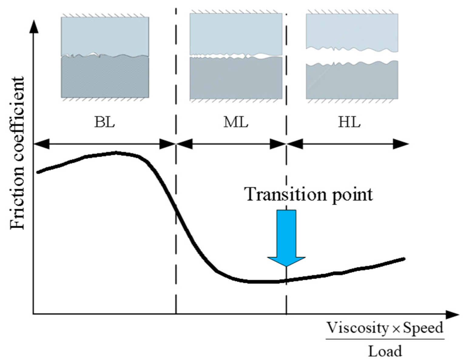
According to the working principle of the end face seal, the medium enters the seal end face and distributes itself, forming a thin lubricating film to reduce friction and wear. Therefore, mechanical seals may experience different tribological states, namely boundary lubrication (BL), mixed lubrication (ML), and hydrodynamic lubrication (HL) states, characterized by the Stribeck curve [3], as shown in Figure 2, and its specific change process. In Figure 2, the transition point corresponds to the place where the friction coefficient reaches the lowest point. By further increasing the speed or decreasing the load, the contact between the friction surfaces is almost completely isolated by the lubricating film, and the friction coefficient reaches the minimum and tends to be stable. This marks the transition from ML to HL. In the ML stage, the friction coefficient decreases with an increase in the abscissa, which is mainly related to the formation of lubricating film and a decrease in surface contact. In the ML stage, as the speed increases or other conditions improve, the thickness of the lubricating film gradually increases. At the same time, the contact area decreases with an increase in film thickness. Therefore, the friction coefficient decreases.
Tribology is a science and technology that studies the production, change, development, and application of friction, wear, and related phenomena on relative moving and interacting surfaces [4]. The various behaviors that occur in relative motion, interacting surfaces, and between surfaces are collectively referred to as tribological behaviors [5,6]. Research on the mechanism of face sealing of mechanical seals based on tribological behavior has always been a research hotspot in the field of mechanical seals. Typical research directions include (1) influence laws of face liquid film characteristics [7,8]; (2) influence of thermal, force–fluid–solid coupling deformation on the face [9,10,11]; (3) influence laws of face morphology [12,13]; (4) leakage mechanism of face seal [14,15], etc. In addition, research on the three tribological mechanisms is also a current hot area. That is, viscous friction due to the shearing of the lubricating layer [5,16,17], deformation of the rough body due to the interaction between the surface rough body and fluid [18], and direct contact with the rough body [17,18,19,20]. Simulating liquid film flow and lubrication regimes at mechanical seal interfaces is fundamental to their numerical analysis. Consequently, much of the domestic and international research focuses on these simulations.
Lubricants are widely used in mechanical seals, which can reduce friction and wear, prolong the life of mechanical equipment, and improve energy efficiency. Under high temperatures and high pressures, the influence of the performance of oil-based lubricants on tribological behavior is related to the specific performance of mechanical seals. Seyed Borhan Mousavi [21] compares the tribological and thermophysical features of the lubricating oil using MoS2 and ZnO nano-additives. He found that pure oil containing 0.7 wt% of each nanoparticle increased the flash point because of its small size and surface-modifying behavior compared to pure oil. Moreover, the addition of ZnO nanoparticles with pure oil lubricant is more suitable than MoS2 nanoparticles for improving the thermophysical properties of pure oil. Seyed Borhan Mousavi [22,23] proposed a synthetic lubricant with exceptional physicochemical properties, emphasizing durability and high efficiency. This is achieved by incorporating a synthesized Cu/TiO2/MnO2-doped GO nanocomposite as an additive at 0.3 wt% concentration and various ratios. Saeed Zeinali Heris [24] prepared two different diesel oil-based nanofluids and examined the influence of temperature and nanoparticle content on the viscosity, tribological, and physicochemical features of diesel oil. Atiyeh Aghaei Sarvari [25] evaluated the effects of multi-walled carbon nanotubes (MWCNTs) and TiO2 nanoparticles (NPs) on lubricant and fluid flow in turbines. It was found that with an increase in nanoparticle concentration, the viscosity and pressure drop of the prepared nanofluids increased with an increase in nanoparticle concentration. With an increase in the volume flow rate, the pressure drop of the nanofluid also increases. The latest research on oil-based lubricants is of great significance for improving the performance of mechanical seals and realizing the tribological behavior characterization of mechanical seals.
Various performance monitoring methods have been explored to evaluate the lubrication regime and contact severity between faces in mechanical seals. Zhang [26] used an eddy current sensor embedded in the mechanical seal stationary ring to directly measure the thickness of the liquid lubrication film and then estimated the face liquid film thickness using an artificial neural network. However, the eddy current sensor used in this method is too large for industrial applications. Huang [27] defined five sealing performance parameters to describe the contact between the sealing surfaces and the corresponding pressure distribution shape, thereby characterizing the dynamic behavior of the mechanical seal. While this method provided a way to study the dynamic characteristics of seals, it did not propose a measurement method to monitor these parameters. Luo [28] proposed a method to analyze the vibration characteristics of the wear degree of mechanical seal faces, using time domain characteristic parameters to identify seal failure. This method set a precedent for the vibration monitoring of mechanical seals, but it relied on the vibration monitoring of the centrifugal pump shell and did not directly collect face signals, resulting in signal distortion issues. Furthermore, existing research on mechanical seal condition monitoring is limited and lacks comprehensive failure detection for specific operating conditions. At present, it is urgent to propose an efficient method for monitoring the condition of mechanical seals, and the proposed method needs to be scientific and practical.
This paper proposes a method to characterize the tribological behavior of mechanical seals using face vibration acceleration measurements, aiming to enhance performance monitoring of these seals. Based on the research in the article [29], this paper further enriched and improved the test scheme and source mechanism model, laying a foundation for further tribological behavior characterization based on face vibration acceleration.
This paper first establishes a mathematical model of the source mechanism of mechanical seal face vibration acceleration and correlates the level of vibration acceleration signal with the tribological behavior of the mechanical seal. Subsequently, a mechanical seal tribological behavior test bench is built to comprehensively simulate and observe the stationary ring dynamic behavior characteristics of the mechanical seal under different tribological regimes. Then, the correlation between the dynamic behavior characteristics of the stationary ring and the vibration acceleration of the mechanical seal is explored. Finally, the main research content of this article is summarized.

2. Mathematical Model

The contact mechanical seal is always in the state of mixed lubrication during normal operation. The main tribological mechanisms include viscous friction and direct contact with rough surfaces due to the shear of the lubricating layer. In this paper, a mathematical model of the acceleration source mechanism based on the above two mechanisms is established to illustrate the source mechanism of the face vibration acceleration of the mechanical seal.

2.1. Viscous Shear Model

To analyze the source of vibration acceleration on the mechanical seal face, the study first calculates the fluid film pressure between seal faces exhibiting irregular shapes and multi-degree-of-freedom motion. This is achieved using the generalized Reynolds equation for liquid film lubrication, which is formulated as follows [30]:
x h 3 12 μ p x + y h 3 12 μ p y = U 2 h x
where x represents the relative motion of the sealing ring in the tangential direction, y represents the relative sliding of the sealing ring in the radial direction, h represents the thickness of the liquid film between the faces, p represents the sealing fluid pressure, μ represents the dynamic viscosity of the sealing fluid, and U represents the tangential relative movement displacement of the sealing ring.
For mechanical seals, Equation (1) is converted into the Reynolds equation in polar coordinates as follows [4]:
1 r θ h 3 12 μ p θ + r r h 3 12 μ p r = r ω 2 h θ
where r represents the calculated radius of the sealing face, θ represents the relative rotation angle of the sealing face, ω represents the angular velocity of the sealing face, p represents the sealing fluid pressure, μ represents the dynamic viscosity of the sealing fluid, and h represents the thickness of the liquid film between the faces.
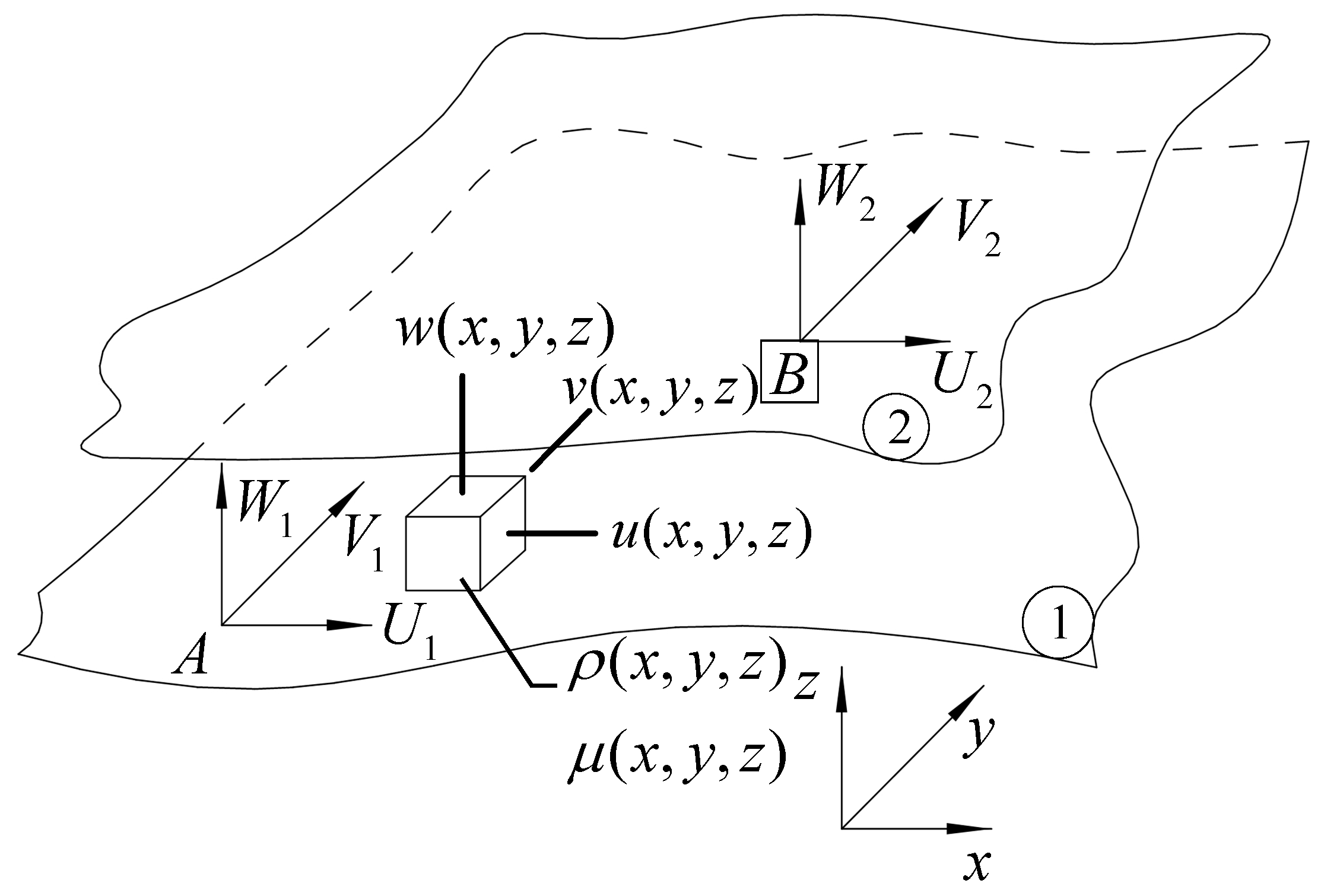
As shown in Figure 3, the fluid control volume element of the sealing surface in Cartesian coordinates and polar coordinates is established. U 1 , V 1 , and W 1 are the velocity vectors in the three directions of the first surface x , y , and z , respectively, U 2 , V 2 , and W 2 are the velocity vectors in the three directions of the second surface x, y, and z, respectively, u ( x , y , z ) , v ( x , y , z ) , and w ( x , y , z ) are the velocity vectors of the fluid film in the x, y, and z directions, and ρ ( x , y , z ) and μ ( x , y , z ) are the density and dynamic viscosity of the fluid, respectively. ① and ② represent the first and second faces respectively, and A and B represent the coordinate systems of the first and second faces respectively.
According to the Reynolds equation, it can be seen that the main influencing factor of the face pressure distribution is the face fluid film thickness. When the film thickness and the roughness peak are of the same magnitude, the influence of the face surface roughness should also be considered. Therefore, when establishing the viscous shear model between seal faces, the three components of fluid pressure, contact pressure, and friction force are calculated, respectively.
1.
Calculation of bearing capacity components
Under mixed lubrication conditions, fluid pressure and contact pressure together constitute the total bearing capacity component of the face. When the fluid pressure magnitude is greater than the contact pressure, the face tribological state is hydrodynamic lubrication. When the contact pressure magnitude is greater than the fluid pressure, the face tribological state is boundary lubrication. The contact of asperities between the faces cannot prevent the flow of fluid between the faces, so the average film thickness between the faces determines the distribution of fluid pressure. In some areas where the asperities are in contact, the contact pressure is stronger than the fluid pressure.
In order to simplify the model, the following two basic assumptions are made: when there is no asperity contact on the face or no asperity contact is about to occur, the fluid pressure dominates the bearing capacity; and when there is or is about to be asperity contact on the face, the contact pressure dominates the bearing capacity.
The total load-bearing capacity resulting from fluid pressure and contact pressure is as follows [31]:
W = A ( p f + p m ) d A = 0 2 π r i r o ( p f + p m ) r d r d θ
where W is the total bearing capacity, p f is the fluid pressure, p m is the contact pressure, A is the face area, r is the face calculation radius, r i is the face inner diameter, and r o is the face outer diameter; p m is calculated as follows:
p m = b m S c
where S c is the flow stress, which is generally equal to three times the tensile yield strength or indentation strength of the material, and b m is the fraction of the total area of the contact area:
b m = P ( H < 0 ) = h f ( z ) d z = f ( h )
where P ( H < 0 ) represents the probability of H < 0 , H represents the film thickness obtained by the uncorrected or original rough surface, h represents the nominal film thickness, z is the height function of the face roughness peak, f ( z ) is the Gaussian function of the face roughness peak distribution, and f ( h ) is the Gaussian distribution function of the liquid film thickness.
2.
Calculation of friction force components
Friction mainly comes from two aspects, viscous shear and contact friction. Therefore, the viscous shear force and contact friction force equations of the mechanical seal face are first established.
In the full film lubrication area, regardless of the effect of cavitation, the total circumferential friction force of the mechanical seal at the average radius is as follows [32]:
F f = 1 r m 0 2 π r i r 0 μ r ω h h 2 p r θ r 2 d r d θ
where r m is the average radius, r i is the inner diameter of the face, r o is the outer diameter of the face, μ represents the dynamic viscosity of the sealing fluid, r represents the calculated radius of the sealing face, θ represents the relative rotation angle of the sealing face, ω the angular velocity of the sealing face, p represents the sealing fluid pressure, μ represents the dynamic viscosity of the sealing fluid, and h represents the calculated thickness of the liquid film between the faces.
In the micro-roughness peak contact area, the contact friction force is equal to the product of the micro-roughness peak shear strength and the contact area. The tangential contact friction force is as follows [4]:
F m = 1 r m 0 2 π r i r 0 τ m r 2 d r d θ
where r m is the average radius, r i is the inner diameter of the face, r o is the outer diameter of the face, r represents the calculated radius of the sealing face, θ represents the calculated rotation angle of the sealing face, and τ m represents the contact friction stress:
τ m = p m f c
where p m represents the local average contact pressure, and f c represents the boundary friction factor.
Therefore, the total friction caused by viscous shear and contact friction is
F = 1 r m 0 2 π r i r 0 μ r ω h h 2 p r θ + τ m r 2 d r d θ
3.
Mathematical model of viscous shear
Using Newton’s second law, the mathematical relationship between face pressure and vibration acceleration is established.
First, we calculate the face flow rate and establish a control body volume model, in which the radial flow rate and the circumferential flow rate of the fluid are
q θ = h 3 12 μ p r θ + r ω h 2
q r = h 3 12 μ p r
where q θ represents the flow rate of the fluid along the radial direction, q r represents the flow rate of the fluid along the circumferential direction, h is the nominal film thickness, μ represents the dynamic viscosity of the sealing fluid, r represents the calculated radius of the sealing face, θ represents the relative rotation angle of the sealing face, ω represents the sealing face angular velocity, and p represents the sealing fluid pressure.
The radial and circumferential volumes of the fluid are, respectively, as follows:
V θ = 0 2 π r i r o ( h 3 12 μ p r θ + r ω h 2 ) r 2 d r d θ Δ t
V r = 0 2 π r i r o ( h 3 12 μ p r ) r d r d θ Δ t
where V θ represents the volume of the fluid along the radial direction, and V r represents the volume of the fluid along the circumferential direction.
Finally, the face acceleration is calculated according to Newton’s second law.
The face acceleration in the film thickness direction, that is, the axial direction, is
a z = W / m = 0 2 π r i r o ( p f + p m ) r d r d θ ρ ( V θ + V r ) t
The radial face acceleration in the sliding direction is
a y = F / m θ = 1 r m 0 2 π r i r 0 μ r ω h h 2 p r θ + τ m r 2 d r d θ ρ V θ t
The circumferential face acceleration in the sliding direction is
a x = F / m r = 1 r m 0 2 π r i r 0 μ r ω h h 2 p r θ + τ m r 2 d r d θ ρ V r t
In the formula, a z represents the axial face acceleration, a y represents the radial face acceleration, a x represents the circumferential face acceleration, W represents the liquid film bearing capacity, F represents the friction force, V θ represents the volume of the fluid along the radial direction, and V r represents the fluid along the circumferential direction. For the volume in the direction, h is the nominal film thickness, μ represents the dynamic viscosity of the sealing fluid, r represents the calculated radius of the sealing face, θ represents the relative rotation angle of the sealing face, ω represents the angular velocity of the sealing face, p represents the sealing fluid pressure, m represents the total mass of the liquid film, m θ represents the radial liquid film mass, m r represents the circumferential liquid film mass, and Δ t represents the time change rate.

2.2. Micro-Convex Body Contact Model

2.2.1. Rough Surface Contact Deformation

Greenwood and Williamson [32] suggested that the interaction between two engineering planes with roughness R q 1 and R q 2 can be analyzed by simplifying it to the contact of two equivalent surfaces.
p ( z > d ) = d f ( z ) d z
The Hertz formula [32,33] gives the maximum deflection, δ , and other deformation parameters and their relationships in the contact region. For the assumption number per unit area of the micro-convex body for D, any expected contact number given by the type of unit area can be described as follows:
n = D d f ( z ) d z
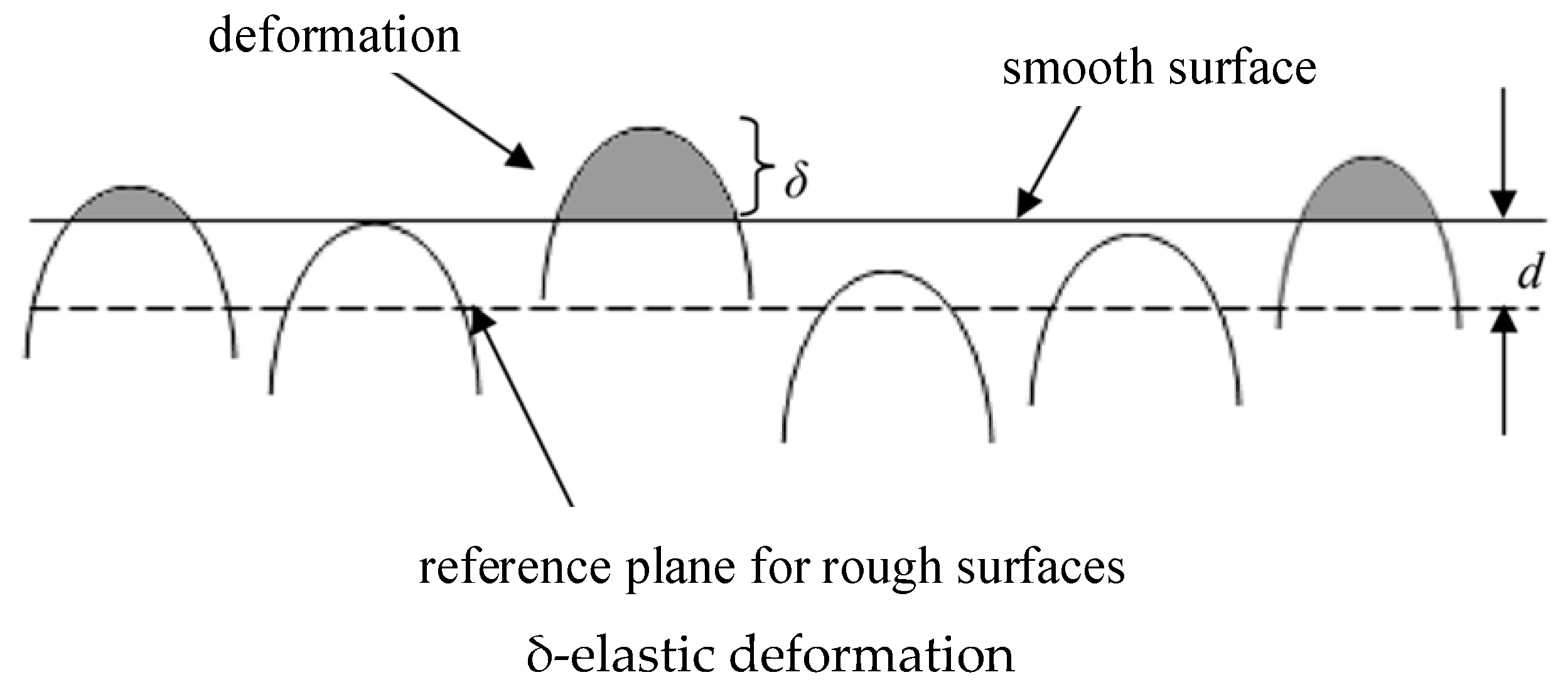
When flow-induced deformation alters the rough surface contact mechanics, traditional models such as Greenwood and Williamson do not suffice. This paper, therefore, introduces a revised definition of their contact model theory. As shown in Figure 4, if the seal gap is filled with a pressurized seal fluid moving at velocity, and the mating surface’s reference plane is separated by distance d, micro-convex bodies taller than d will deform, and elastic deformation is δ. Thus, the new definitions of Equations (17) and (18) can be applied. That is, p ( z > d ) represents the likelihood of micro-convex bodies deforming due to fluid flow at any specific height, while n denotes the average number of such deformations per unit area that are expected to be elastic.

2.2.2. Simulation of Contact Deformation of Asperities

1.
Calculation of friction force of a single asperity
Traditionally, the tangential friction force between asperities in the sliding direction is characterized as follows [34]:
F = A 0 τ d A
where τ is the shear stress of a single asperity acting on area A, A = π r 2 , r is the average radius of the equivalent rough surface given by Hertzian theory, and A 0 is the asperity deformation area of a single asperity. The shear stress in the asperity–asperity (a-a) interaction can be expressed by Equation (20):
τ a a = f σ
where f and σ , respectively, represent the friction coefficient and normal stress at a single asperity contact.
Bringing Equation (20) into Equation (19) and reordering the integrals, the friction force on each equivalent asperity is characterized as follows:
F a a = f W
where W denotes the normal contact load between asperities. Higher peaks in surface roughness experience more bending stress from fluid flow. This means that the nonlinear interaction between fluid dynamics and asperities is taller than d, as shown in Figure 3.
2.
Calculation of contact vibration energy of a single asperity
Assuming asperities act as end-loaded cantilever beams, the vibration energy from dynamic bending during contact with a single equivalent asperity is described by the following [35]:
U i = σ b 2 2 E d V a
where E represents the equivalent elastic modulus as per Hertzian theory, V a is the volume of the equivalent asperity, and σ b denotes the bending stress when the asperity deforms, which can be expressed as
σ b = M y I
where M denotes the bending moment, y denotes the distance from any point on the curved cross-section to the neutral plane, and I denotes the area moment of inertia. The following equation is set up:
d V a = d A d x
The vibration energy generated during the dynamic bending of any equivalent asperity of height x can be described as
U i = 1 2 E M y I 2 d A d x = 1 2 E I M 2 d x
Since elastic deformation (due to direct contact or fluid flow) is assumed to be more significant for asperities with heights greater than d, assuming d x = d δ , the bending moment M can be calculated by
M = F δ
If the friction force keeps invariant during the asperity contact (which means that the deformation radius is smaller than the critical value [36]), substituting Equation (26) into Equation (25) and rearranging the integral gives
U i = 1 2 E I ( F δ ) 2 d δ = F 2 δ 3 6 E I
Substituting F in Equation (21) into Equation (25), the vibration energy leading to asperity–asperity (a-a) interaction is as follows:
U i ( a a ) = f 2 W 2 δ 3 6 E I
Since δ = z d , the average vibration energy produced by the deformation of a single equivalent asperity is given by
U ¯ i ( a a ) = f 2 W 2 6 E I d ( z d ) 3 f ( z ) d z d f ( z ) d z
3.
Calculation of total vibration energy
The total vibration energy U V in the deformation of the elastic rough body can be expressed as
U V = A a n U ¯ i
where A a is the visible deformation region, and n represents the density of deformation per unit region. Substituting Equation (29) into Equation (30), the total vibration energy is as follows:
U V ( a a ) = A a D f 2 W 2 6 E I d ( z d ) 3 f ( z ) d z
By dividing the distance by the sliding speed time, the face vibration contact unit time can be calculated. The deformation length L is inferred from the formula available for the cantilever beam free end displacement (or maximum deflection) [37] setting the length of the beam to δ :
L = F δ 3 3 E I
Substituting (21) into Equation (32), the deformation length is given by
L a a = F W δ 3 3 E I = f r δ 9 2 3 I
The time it takes to deform a single equivalent bump can be determined using the following formula:
t = 2 L V
Therefore, by substituting Equation (33) into Equation (34), we obtain
t a a = 2 f r δ 9 2 3 I V
If we replace δ with z d , then the average unit time is
t ¯ a a = 2 f r d ( z d ) 9 2 f ( z ) d z 3 I V d f ( z ) d z
4.
Calculation of vibration energy generation rate
The total amount of roughness deformation between two surfaces is expressed as
N t o t = A a D d f ( z ) d z
In addition, an auxiliary function can also be defined as follows [38]:
F n ( d * ) = d * ( z * d * ) n ϕ ( z * ) d z *
where z * = z R q and d * = d R q , ϕ ( z * ) are the standard height distribution of rough bodies, and Equation (20) shows that F n ( d * ) is affected by surface spacing d and surface topography characteristics. Studies indicate that the spacing d is influenced by the surface topography and does not depend on the applied load.
During the frictional contact process of the mechanical seal face, part of the vibration energy and part of the heat energy are generated. Therefore, assuming that part K e of the vibration energy is transformed into vibration surges, the gain of the vibration measurement system is K g ; by dividing Equation (36) by Equation (31), and using Equation (37) to simplify the result, the vibration energy generation rate is given by the following equation:
U ˙ V ( a a ) = K e K g N t o t f W 2 V F 3 ( d * ) 4 E r F 9 2 ( d * )
Equation (39) shows that the generation rate of vibration energy during dynamic bending of surface roughness correlates with the extent of asperity deformation, caused by either direct roughness contact or flow-induced forces. Furthermore, the geometry of the equivalent roughness, particularly r, influences the vibration signal intensity. Additionally, Equation (39) underscores that in direct rough body contact, the vibration energy generation is more sensitive to contact load than to sliding speed.
5.
Calculation of vibration RMS
The RMS of vibration is calculated as the square root of the average of the squared values of the vibration signal over a specific period, and it serves to represent the amplitude of the vibration. It is a statistic of the vibration signal amplitude, which can reflect the intensity or energy of the vibration signal. Therefore, this paper utilizes the RMS of the vibration acceleration signal to assess the tribological state of the mechanical seal. Considering the assumptions of Ibrahim [39] and others, the relationship between the RMS of vibration and vibration energy is
V r m s ( a a ) = U ˙ V ( a a ) = W 2 r 1 4 K e K g N t o t f V F 3 ( d * ) E F 9 2 ( d * )
According to Equation (40), the RMS of the vibration acceleration of the face is determined by the total number of asperity contacts and the rotational speed under stable working conditions, so the formula can be simplified to
V r m s ( a a ) = C 1 N t o t V
Under mixed lubrication conditions, we believe that due to the improvement of lubrication conditions, with an increase in sliding speed, the number of rough contacts decreases. Before the fluid film is formed in the sealing gap, the sealing surface contacts together. When the device starts to rotate, the sliding speed and film pressure are very low, the sealing surface is not separated, and direct contact occurs between surfaces without lubricating films. At a lower sliding speed, the load is completely carried by the asperities interacting with the contact surface. With an increase in rotational speed, due to the accumulation of hydrodynamic pressure caused by the rotational motion of the mating surface [5], the surface begins to not contact with each other and is separated by the fluid film. Therefore, with an increase in sliding speed, the lubrication conditions are improved, and the number of rough contacts is reduced. Therefore, under mixed lubrication conditions, the relationship between the number of asperities and the sliding speed is as follows:
N t o t = C 2 V
Substituting Equation (42) into Equation (43), the relationship between RMS and sliding speed is
V r m s ( a a ) = C 3 V 1 2
In Equations (41)–(43), C 1 , C 2 , and C 3 are constants.
It can be seen from the theoretical formula that RMS decreases with an increase in rotational speed, which is consistent with the experimental results.
According to Equation (40), the relationship between RMS and surface asperities is positively correlated. That is, when the rotational speed and medium pressure are constant, the RMS increases with an increase in the number of surface asperities. Then, Equation (40) can be rewritten as
V r m s ( a a ) = C 4 N t o t 1 2
In this experiment, an increase in surface roughness means an increase in the number of surface asperities. Therefore, the relationship between the number of surface asperities and surface roughness is
N t o t = C 5 R a
The relationship between RMS and surface roughness is
V r m s ( a a ) = C 6 R a
In Equations (44)–(46), C 4 , C 5 , and C 6 are constants.
The RMS increases with an increase in surface roughness, which is consistent with the experimental results.

3. Experimental Validation

3.1. Construction of Mechanical Seal Test Rig

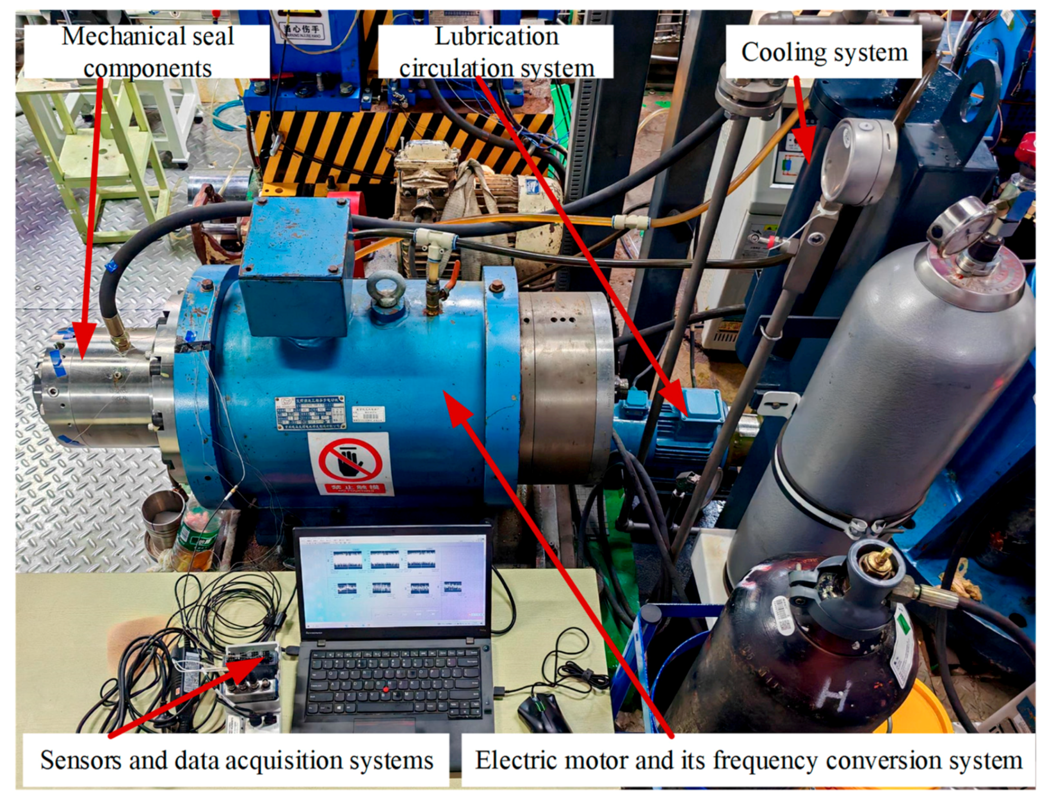
A mechanical seal tribological behavior test bench was designed and built, as shown in Figure 5, including mechanical seal components, motors, lubrication circulation systems, cooling systems, sensors, and data acquisition systems. The new device design of the test bench brings several advantages to the system:
  • The test device replicates common seal arrangements found in industrial applications, such as mechanical seal arrangements for pumps;
  • Ensure sealing ring centering control during the design and installation process;
  • The replacement of seals becomes simple and can be completed in only twenty minutes.
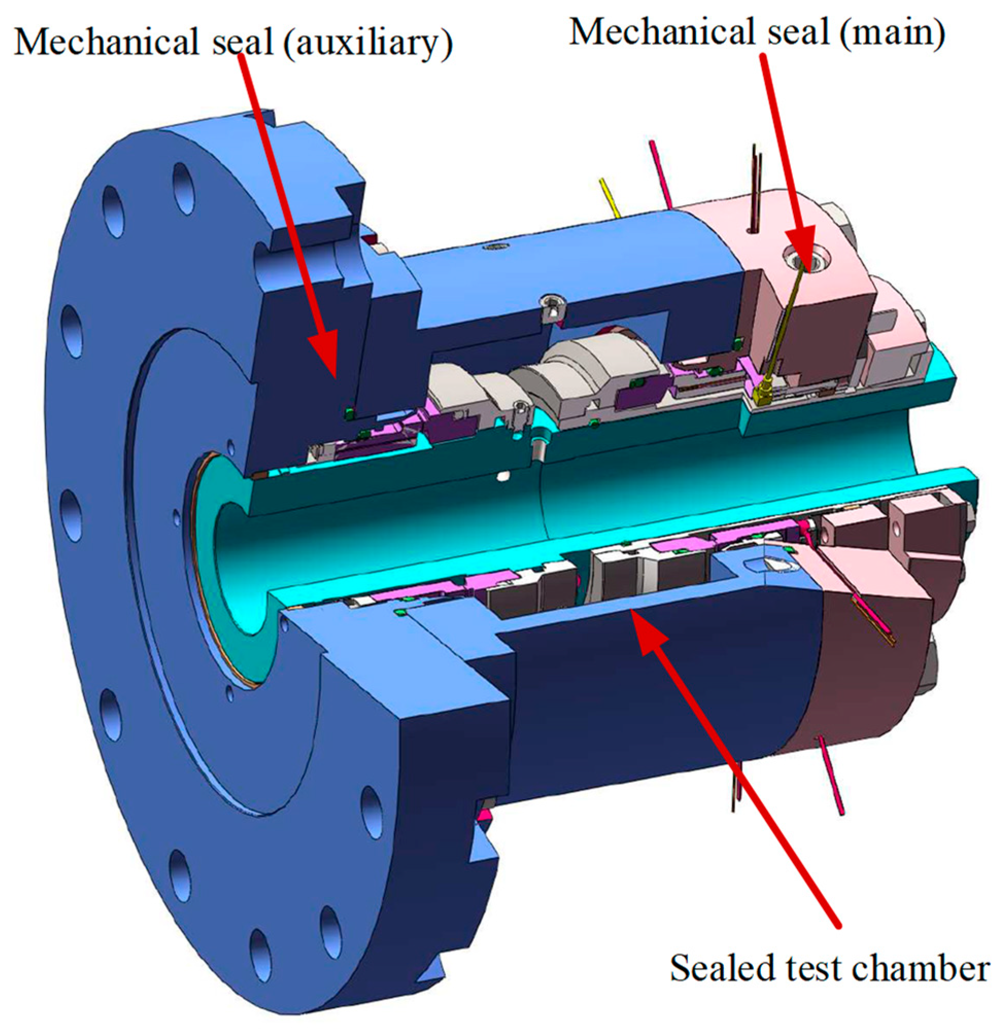
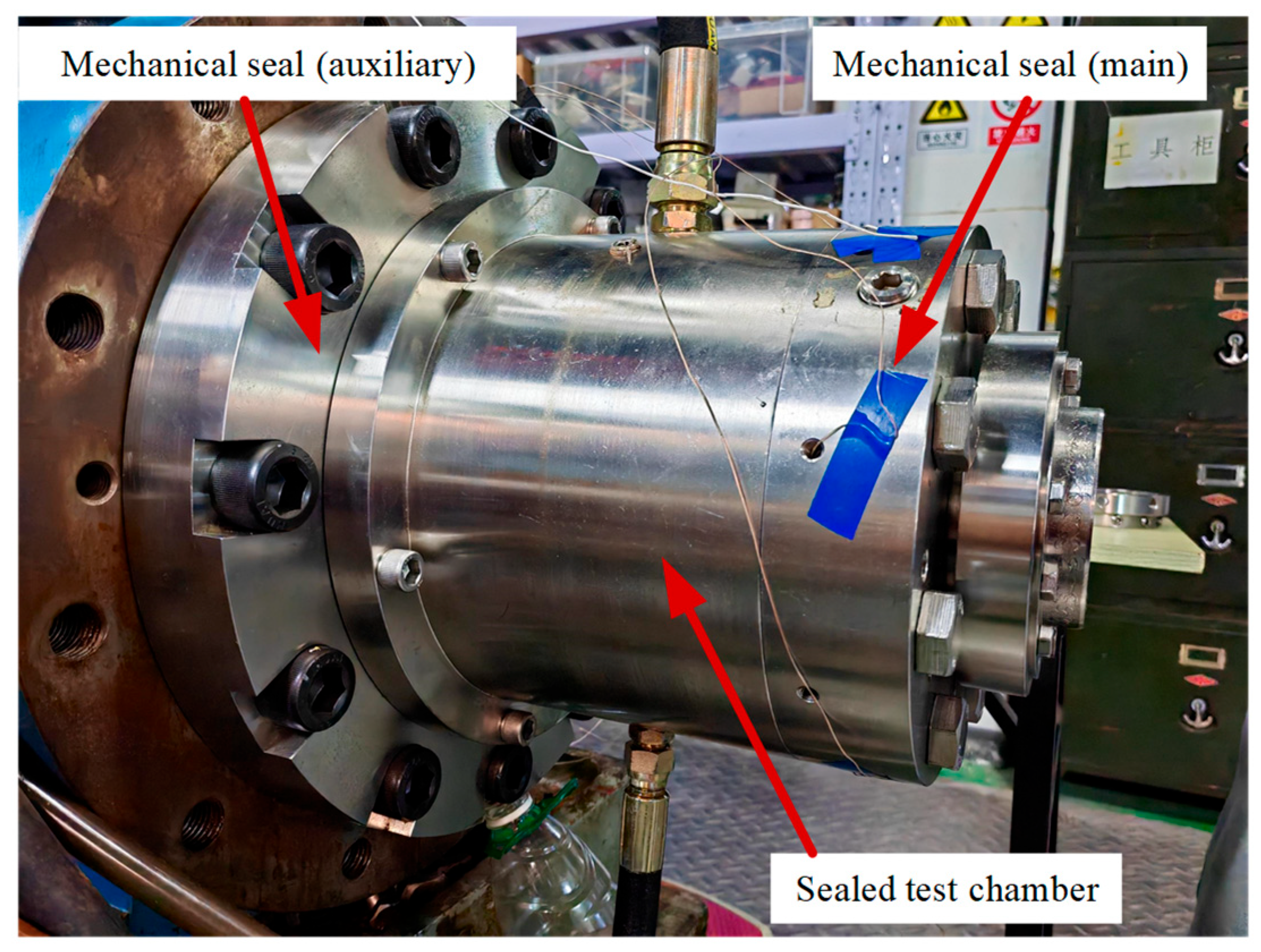
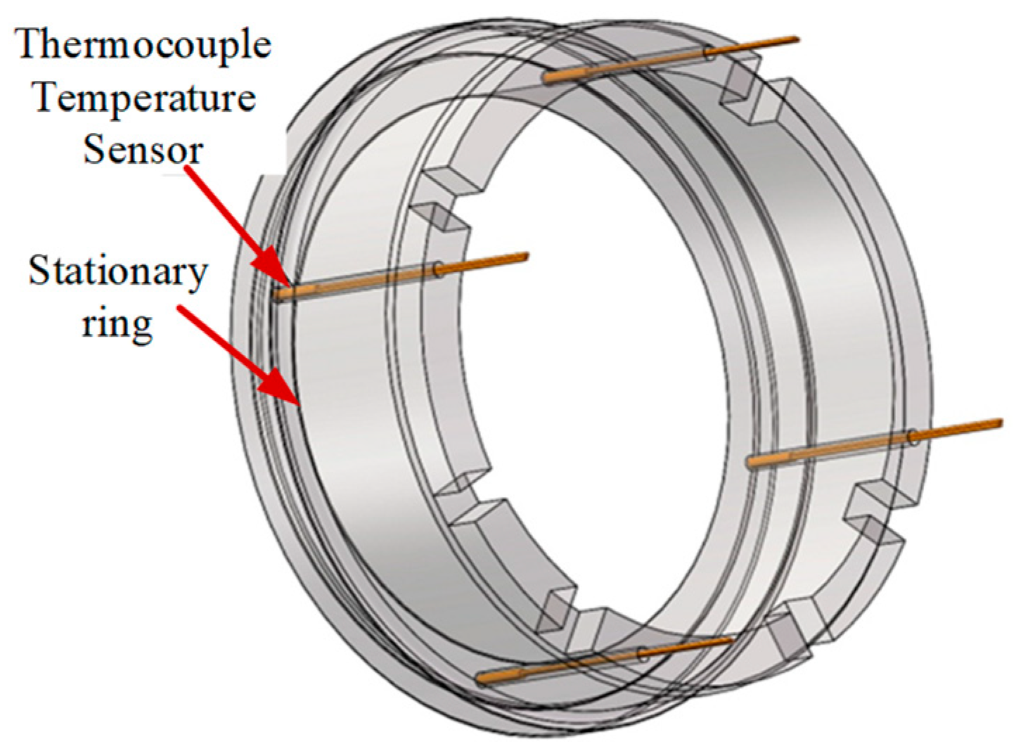
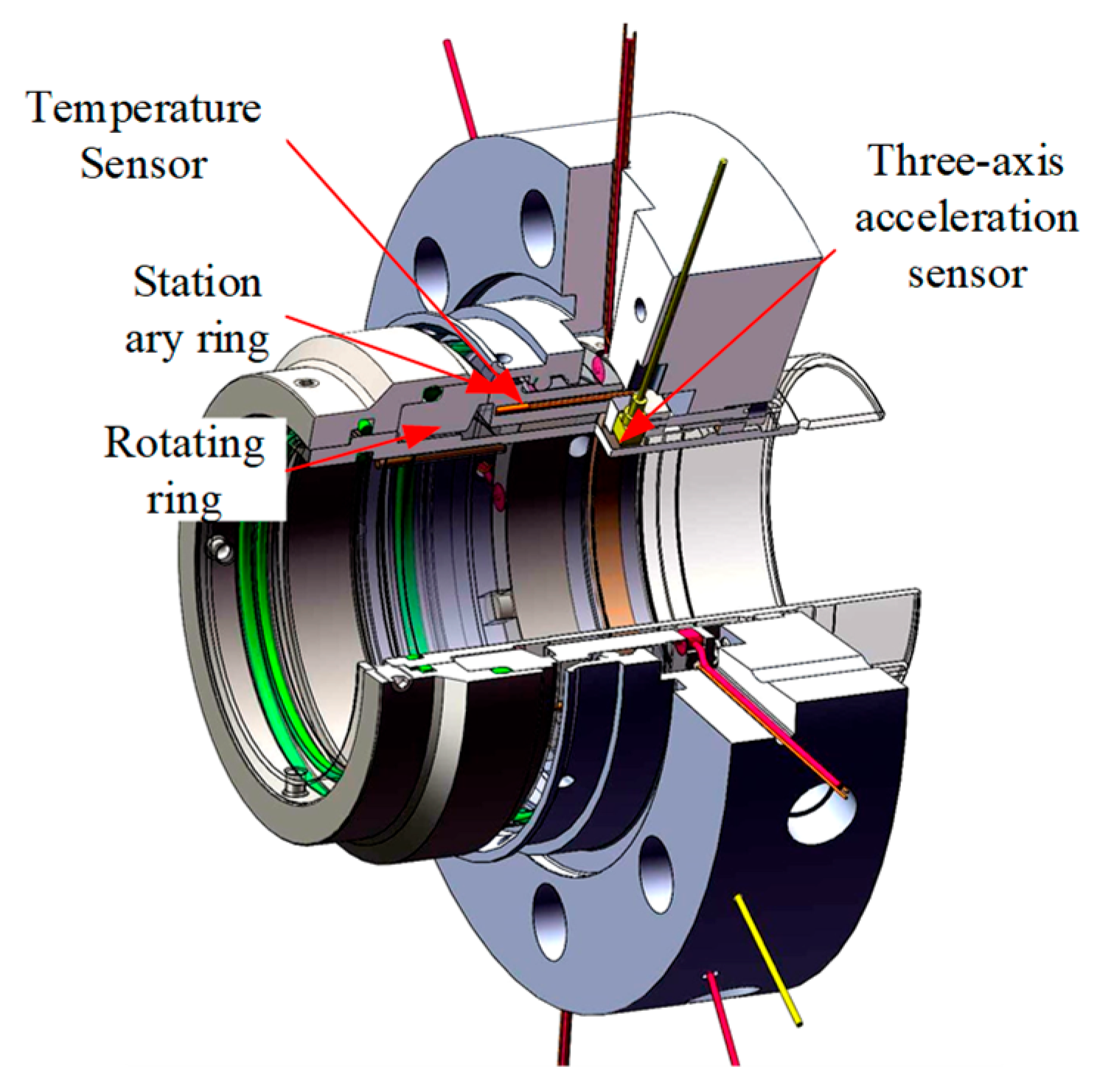
As the core test component of the entire test bench, the mechanical seal assembly mainly consists of the mechanical seal (main), the mechanical seal (auxiliary), and the sealing test chamber. In order to ensure the engineering applicability of the test bench, the industrial mechanical seal of the ZLM IP 530/06 oil transfer pump made by Ruhrpumpen (Monterrey, Mexico) is used, not just a pair of disk seal friction pairs, which is suitable for a shaft with a diameter of 96 mm; the sealing pair material is SIC-SIC, and the detailed information of the friction pair is shown in Table 1. The sealing medium used is turbine engine aviation lubricating oil. As shown in Figure 6, the mechanical seal (main) is a single-end contact mechanical seal, which consists of a rotating ring, a stationary ring, a push ring, and a cavity. The actual picture is shown in Figure 7. The mechanical seal (auxiliary) has the same structure as the mechanical seal (main). Its main function is to prevent the sealing medium from leaking to the motor side; the main and auxiliary seals are arranged back to back, which can balance the axial force. As shown in Figure 8, four thermocouple sensors are embedded in a blind hole with a diameter of 2 mm on the back of the mechanical seal (main) stationary ring. Figure 9 shows the mechanical seal equipped with a sensor, where two three-axis acceleration sensors are embedded in the mechanical seal (main) in the groove on the back of the stationary ring, this can ensure that the waveform distortion is reduced to the smallest possible level. The parameters of the vibration acceleration sensor are shown in Table 2, and the parameters of the temperature sensor are shown in Table 3.
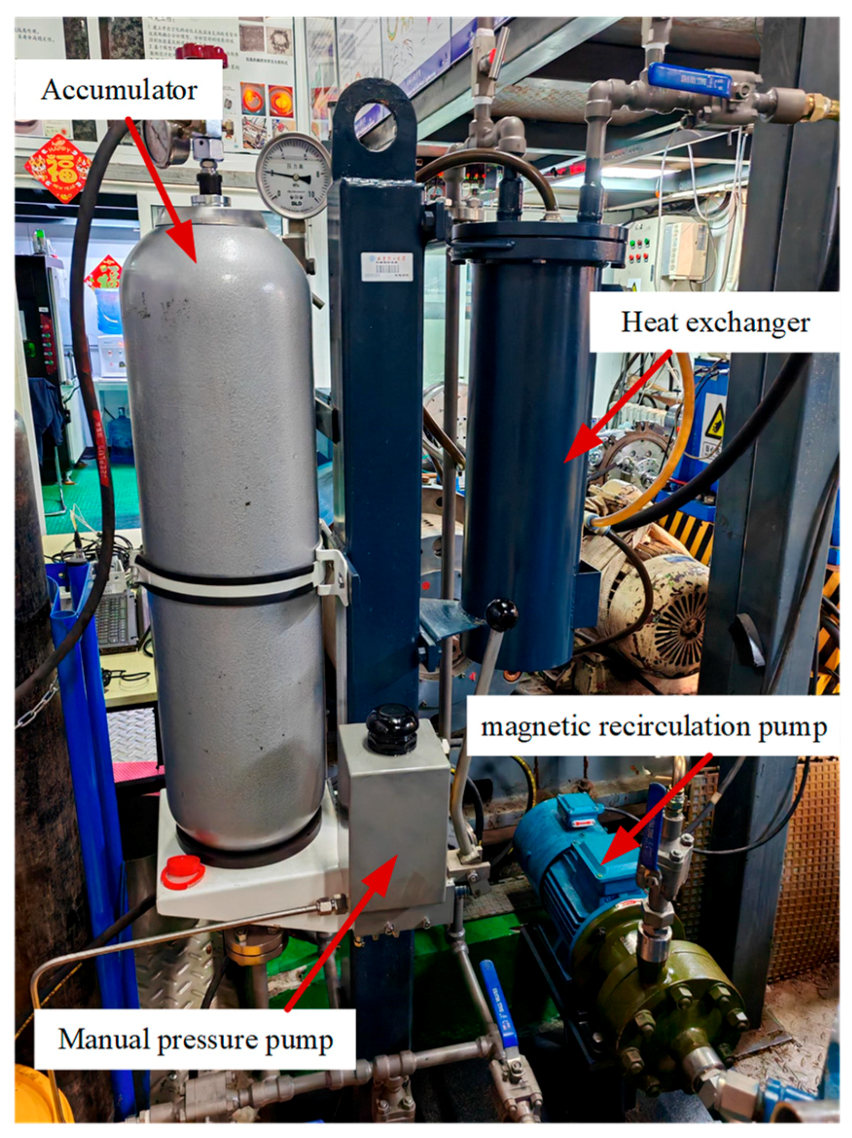
The lubrication circulation system includes a magnetic circulation pump, a manual pressure pump, an accumulator, a regulating valve, a pressure gauge, and ancillary pipelines, as shown in Figure 10. The magnetic circulating oil pump transports aviation lubricating oil from the heat exchanger to the sealed cavity. A manual pressurizing pump is used to adjust the pressure of the sealed cavity. An accumulator is used to maintain the set pressure stable. The lubricating oil transfers the heat generated by the friction pair to the heat exchanger. Among them, the model of the magnetic circulation pump is CQBQ25-12, with a flow rate of 8–24 m3/h, a lift of 12 m, a power of 1.5 kw, a rotation speed of 2900 r/min, and inlet and outlet pressures that can meet the pressure resistance condition of 6.5 MPa. The accumulator model is 20/10-L-Y, with a volume of 20 L, and a design pressure of 20 MPa. It is a bladder-type accumulator, which plays the role of storing energy, recovering energy, and eliminating pulsation. The gas medium in the accumulator is high-purity nitrogen. The lubricating oil parameters used are shown in Table 4.
The cooling system includes heat exchangers, air-cooled chillers, tank cooling coils, valves, pipelines, etc., as shown in Figure 10. Circulating cooling water is used to cool the lubricating oil and the variable frequency motor housing. Its main function is to transfer the friction heat absorbed by the lubricating oil to the cooling water, ensuring that the lubricating oil can carry away more friction heat generated by the face. Among them, the heat exchange area of the heat exchanger is 0.6 m2, and the operating pressure is 6.3 MPa.
The data acquisition system consists of an NI 9174 chassis, an NI 9234 data acquisition card, an NI 9219 data acquisition card, a thermocouple temperature sensor, a piezoelectric three-axis acceleration sensor, and a LabVIEW virtual instrument. Data acquisition will involve measuring the required variables, such as temperature, voltage, and current, and converting them into electronic signals, which will be saved, processed, and viewed using LabVIEW virtual instruments.
The motor and its frequency conversion system mainly include a variable frequency speed-regulated three-phase asynchronous motor, a frequency converter, and a console. The variable frequency speed-adjustable three-phase asynchronous motor is selected with the characteristics of good heat transfer performance, high quality, and high power. The rated frequency is 100 Hz, the power is 40 kW, and the voltage is 380 V. The variable frequency speed regulation motor is installed on the cement base, which effectively reduces the influence of the motor and external vibration on the vibration of the mechanical seal face. The circulating cooling system is used to cool the motor rotor to achieve better thermal control. In order to realize the relationship between mechanical seal face vibration and rotation speed and increase the speed incrementally under constant pressure, a speed controller is needed so that the motor can run at different speeds. An INVT CHV100 high-performance vector produced in Guang Zhou Matu (Guangzhou, China) frequency converter is selected to set the number of motor steps, operating time, and AC motor speed to achieve continuous changes in the three-phase asynchronous motor speed from 0 to 6000 r/min.

3.2. Tribological Behavior Change Test of Mechanical Seal

This paper uses the RMS of vibration acceleration to characterize the changing rules of the tribological behavior of mechanical seals. The RMS is an important physical quantity that represents the intensity of vibration. It helps to understand the interaction of friction surfaces and predict the wear of friction pairs, thereby evaluating the tribological state between faces. At the same time, temperature is an important indicator for the current monitoring of the tribological behavior of mechanical seals, which can intuitively characterize the performance of mechanical seals. This paper uses the temperature index as an auxiliary index of the face vibration acceleration index to facilitate the analysis of the intrinsic factors that change with tribological behavior.
This paper uses the control variable method to conduct experiments. That is, under the condition of changing speed, the controlled medium pressure and face surface roughness remain unchanged. Under the condition of changing medium pressure, the controlled speed and face surface roughness remain unchanged. When the surface roughness of the face changes, the controlled speed and medium pressure remain unchanged. Three sets of experiments were conducted to explore the variation pattern of face vibration acceleration RMS with rotation speed, medium pressure, and face surface roughness. In addition, the changing rules of face vibration acceleration RMS during the start and stop stages of the mechanical seal were explored.

3.2.1. Mechanical Seal Start–Stop Experiment

Mechanical seal failure is a common problem in current engineering applications. Research shows that approximately 60% of mechanical seal failures occur during seal start-up and trial operation. Under these two working conditions, the mechanical seal is in the transition stage between boundary lubrication and mixed lubrication. There are many micro-protrusions in contact, and the friction coefficient is high, which seriously affects the service life of the mechanical seal. Since the start-up and stop processes of equipment are common, it is of great significance to study the start-up and stop processes of mechanical seals to obtain their characteristics and change patterns.
In order to solve the problem of the unknown change pattern of the effective value of end face vibration during the start and stop stages of the mechanical seal, a start-up and stop test of the mechanical seal was carried out. The test explores the changing trend in the Stribeck curve during the start and stop stages of the mechanical seal, that is, the coordinate system in which the abscissa is the speed and the ordinate is the effective value of the face vibration acceleration. The changing trend in the curve in this coordinate system is consistent with the changing trend in the Stribeck curve where the abscissa is the rotational speed × hydrodynamic viscosity/sealing surface specific load and the ordinate is the friction coefficient, which is called a Stribeck-like trend. The vibration acceleration signal of the mechanical seal face is collected, and the RMS of acceleration is used to characterize the Stribeck-like curve change trend in the tribological behavior of the mechanical seal during the start and stop stages.
The evolution of the mechanical seal state during the start and stop process is studied through the mechanical seal tribological behavior test bench. The test process is as follows: the total time of one start and stop is 180 s, of which the start time, full-speed time, and stop time are 60 s. In addition, the sealing medium pressure is 1.6 MPa, and the working speed is 3000 r/min. The main signals collected are the face vibration acceleration signal and the face temperature signal, which are collected through the data acquisition system. In order to capture the details of vibration signals at higher frequencies and improve the resolution and accuracy of spectral analysis, considering the Nyquist theorem, the high-frequency noise in the vibration signal or shock wave is included as much as possible, and a more standard 25,600 Hz is selected as the sampling frequency. The sampling frequency is 25,600 Hz, the number of sampling points is 25,600, and the sampling time is 1 s.

3.2.2. Mechanical Seal Rotation Speed Change Test

Aiming at the unknown variation law of vibration acceleration of mechanical seal with rotational speed, the variation law of RMS of vibration acceleration of face with rotational speed was tested.
The test plan is as follows:
  • Use the manual pressure pump replenishment method shown in Figure 10 to fill the mechanical seal tribology behavior test bench system with lubricating oil, and at the same time, let it reach the test set pressure of 1.6 MPa (which is the actual working pressure of the mechanical seal), and ensure that the lubricating oil viscosity is 32 pa∙s.
  • Set the motor frequency converter frequency to 17 Hz. After ensuring safety, turn on the motor. At this time, ensure that the motor speed is 1000 r/min.
  • Start data collection, and use the LabVIEW virtual instrument to set the face vibration acceleration and face temperature sampling frequency to 25,600 Hz, the sampling time to 1 s, and the number of sampling points to 25,600. At the same time, use the LabVIEW virtual instrument to save the face vibration acceleration data.
  • Collect the face vibration acceleration signal and face temperature signal under the condition of 1000 r/min rotation speed, and ensure that the sampling duration is 1 min.
  • Repeat steps 3 and 4 when the motor speed is 1500 r/min, 2000 r/min, 2500 r/min, and 3000 r/min.
The specific process parameters of the mechanical seal rotation speed change test are shown in Table 5.
Speeds of 1000 r/min, 1500 r/min, 2000 r/min, 2500 r/min, 3000 r/min were selected as the speed point. This is based on the common standard speed, covering a wide operating range, the ease of linear spacing for analysis, the capabilities and limitations of the experimental equipment, and the simulation of actual operating conditions based on previous research and experience. These speed points can provide comprehensive and reliable experimental data for in-depth exploration of the vibration acceleration change law of mechanical seals.

3.2.3. Mechanical Seal Medium Pressure Change Test

Aiming at the unknown problem of the changing pattern of mechanical seal vibration acceleration with sealing medium pressure, a test on the changing pattern of RMS with medium pressure was carried out.
The test plan is as follows:
  • Use the manual pressure pump replenishment method shown in Figure 10 to fill the mechanical seal tribology behavior test bench system with lubricating oil, and at the same time, let it reach the test set pressure of 1.2 MPa.
  • Set the motor frequency converter frequency to 50 Hz and turn on the motor. At this time, ensure that the motor speed is 3000 r/min.
  • Start data collection, and use the LabVIEW (version 2020) virtual instrument to set the face vibration acceleration and face temperature sampling frequency to 25,600 Hz, the sampling time to 1 s, and the number of sampling points to 25,600.
  • Collect the face vibration acceleration signal and face temperature signal under the conditions of 3000 r/min rotation speed and medium pressure 1.2 MPa. Ensure that the sampling duration is 1 min.
  • Use a hand pump to replenish fluid, and repeat steps 3 and 4 under the conditions of medium pressures of 1.3 MPa, 1.4 MPa, 1.5 MPa, 1.6 MPa, 1.7 MPa, 1.8 MPa, 1.9 MPa, and 2.0 MPa.
  • Combine the face vibration acceleration data collected at each pressure gradient into time domain waveform data in three directions: axial, radial, and tangential.
The specific process parameters of the mechanical seal medium pressure change test are shown in Table 6.
The medium pressure range of 1.2 MPa to 2.0 MPa is based on the common industrial pressure range, the influence of pressure on sealing performance, equipment capability, experimental feasibility, avoiding extreme pressure effects, capturing nonlinear effects, based on previous research and experience, and simulation of actual working conditions.

3.2.4. Mechanical Seal Surface Wear Change Test

Aiming at the unknown problem of the vibration acceleration of the mechanical seal changing with the surface roughness of the seal face, a test on a change in the vibration RMS of the mechanical seal face with the surface roughness was carried out.
This test uses a brand-new rotating ring and three rotating rings that have been used in oil pumping stations for a long time and have different levels of wear as variables for changes in the surface roughness of the mechanical seal face. Ra is the most common method of characterizing roughness. It represents the average value of the profile change over the reference length, which is called the centerline average or arithmetic mean. The centerline average is defined as the integral of the absolute value of the roughness profile height over the evaluation length as shown in Equation (47) [41]:
R a = 1 L 0 L z ( x ) d x
where L is the sampling length, and z ( x ) is the height of the surface contour from the center line.
Table 7 shows the surface roughness of four rotating rings measured by using a portable surface roughness meter TR100 with a measuring range of Ra 0.05–15.0 μm. The measurement method is to select eight different points on the mating surface, select a reference point on the rotating ring, and then divide the face of the rotating ring into eight different samples. Match the first data point roughly to the reference point. After that, rotate the sample clockwise to reach the next sample. Finally, calculate the average value of the eight samples as the surface roughness of the ring. Measure the surface roughness of the four rotating rings using this method.
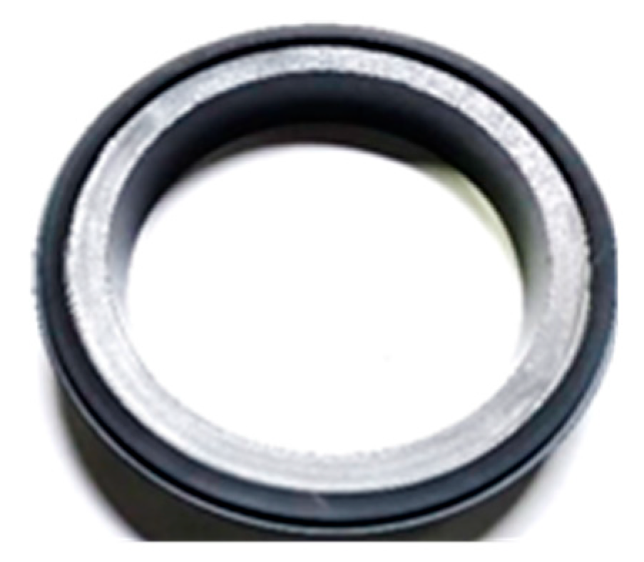
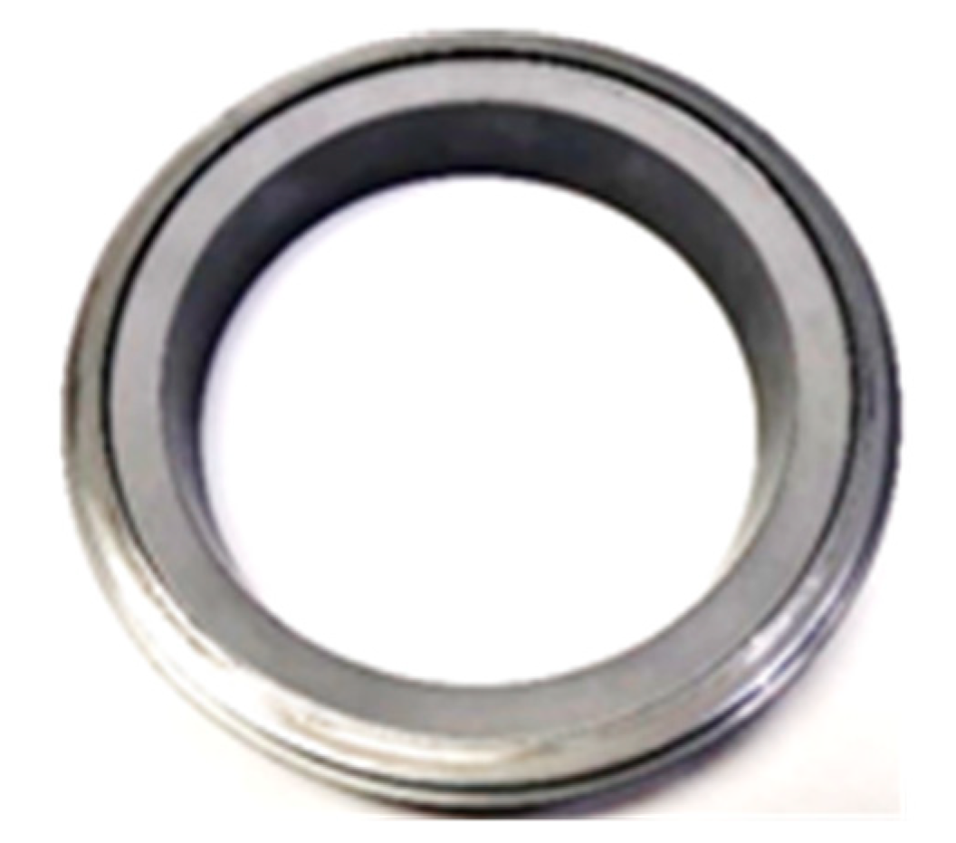
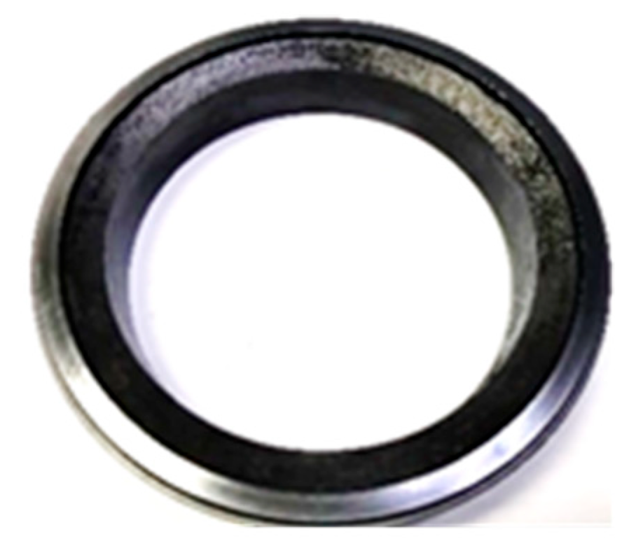
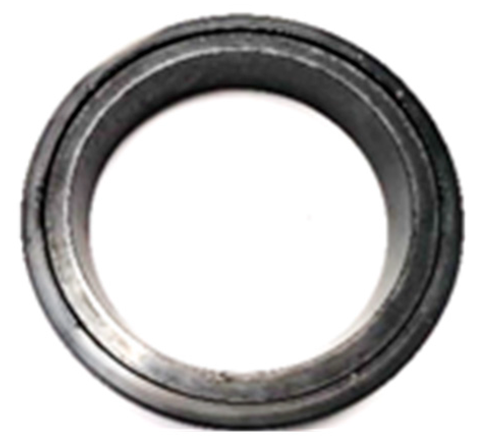
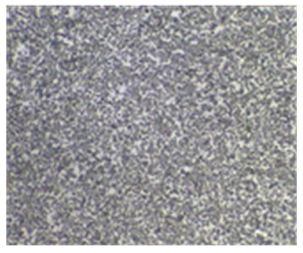
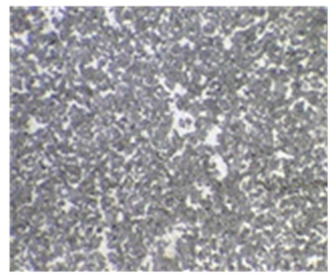
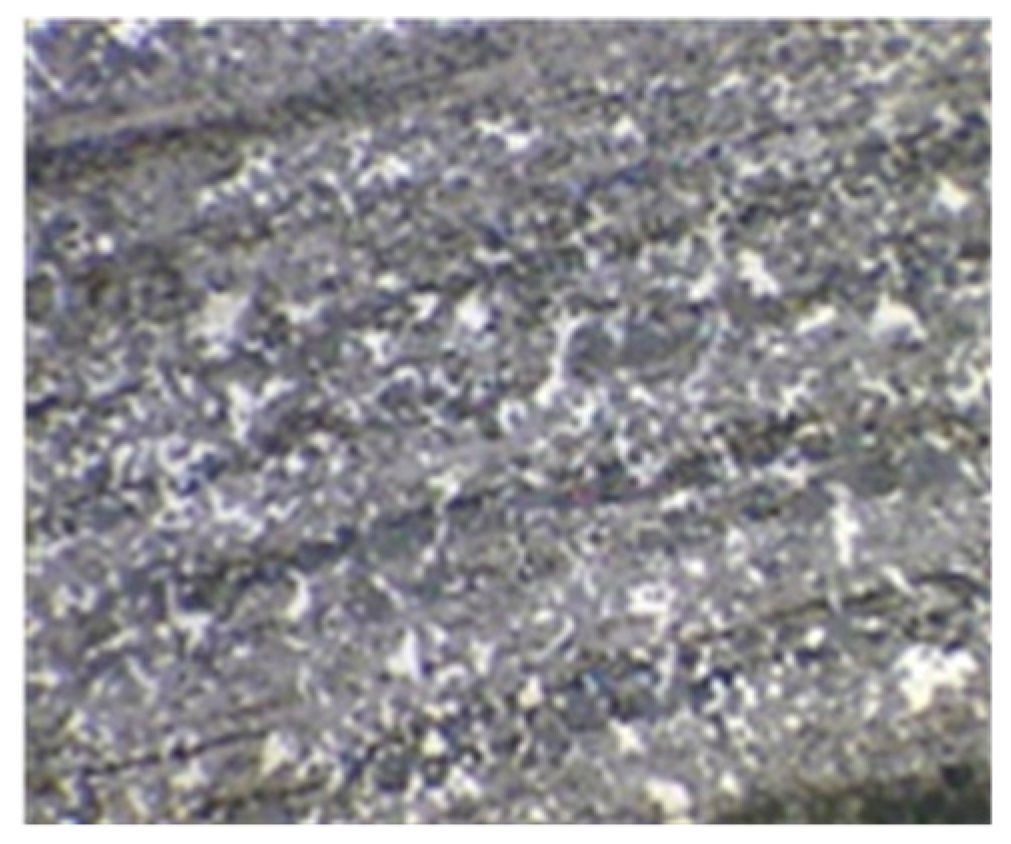
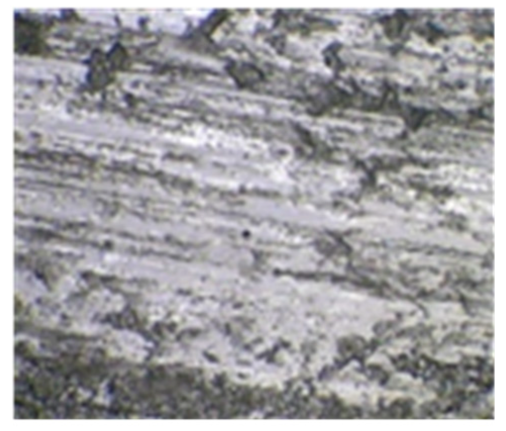
The appearance of the four rotating rings is shown in Figure 11, Figure 12, Figure 13 and Figure 14. The surface images of the four rotating rings measured with the image-measuring instrument are shown in Figure 15, Figure 16, Figure 17 and Figure 18. Rotating rings 1#, 2#, 3#, and 4# are named in ascending order of face wear degree; the face roughness of the 4# rotating ring is 0.32 μm. According to the industry standard of JB/T 4127.1-2013 [42] “Mechanical Seal Part 1: Technical Conditions”, the surface roughness of the hard material seal face is Ra which should not be greater than 0.2 μm, and the 4# rotating ring should be judged as a failed sealing ring.
The test plan for collecting vibration acceleration data of mechanical seal face wear is as follows:
  • Install the 1# rotating ring, use the manual pressure pump to replenish fluid as shown in Figure 10, fill the mechanical seal tribology behavior test bench system with lubricating oil, and simultaneously let it reach the test set pressure of 1.6 MPa.
  • Set the motor frequency converter frequency to 50 Hz and turn on the motor. At this time, ensure that the motor speed is 3000 r/min.
  • Use the LabVIEW data acquisition virtual instrument, set the face vibration acceleration and face temperature sampling frequency to 25,600 Hz, the sampling time to 1 s, the number of sampling points to 25,600, and start data collection.
  • Collect the face vibration acceleration signal and face temperature signal under the conditions of 3000 r/min rotation speed and medium pressure 1.6 MPa. Ensure that the sampling duration is 1 min.
  • After the collection is completed, replace the 2#, 3#, and 4# rotating rings in sequence, and repeat steps 2 to 4 in sequence.
Figure 11 and Figure 15 are the appearance and surface morphology of the rotating ring corresponding to working condition 1. Through observation, the surface quality of the ring is the best, and the surface roughness is 0.07 μm. Figure 12 and Figure 16 show the appearance and surface morphology of the moving ring corresponding to condition 2. Through observation, the surface quality of the ring is worse than that of 1#, and the surface roughness is 0.09 μm. Figure 13 and Figure 17 show the appearance and surface morphology of the moving ring corresponding to working condition 3. Through observation, the surface quality of the ring is worse than that of 2#, and the surface roughness is 0.20 μm. Figure 14 and Figure 18 show the appearance and surface morphology of the moving ring corresponding to condition 4. Through observation, the surface quality of the ring is the worst, and the surface roughness is 0.32 μm. The specific process parameters of the mechanical seal surface wear change test are shown in Table 8.

4. Results

4.1. RMS of Face Vibration Acceleration Change Law during Starting and Stopping Process

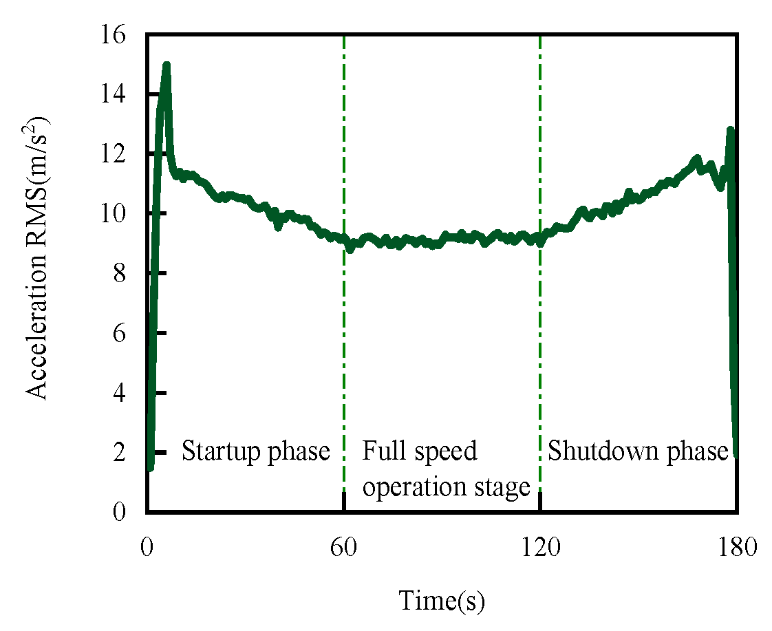
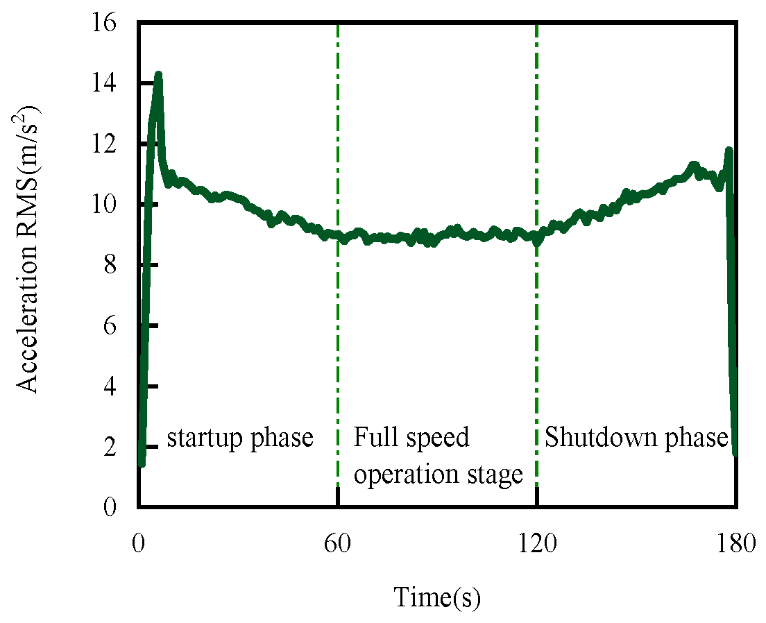
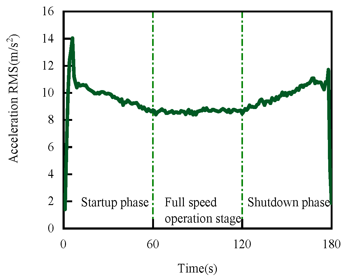
Calculate the RMS data collected in the test of Section 3.2.1, as shown in Figure 19, Figure 20 and Figure 21.
When the mechanical seal starts, as the rotational speed increases, the tribological state transitions from boundary lubrication to mixed lubrication, while the opposite happens when the mechanical seal is shut down. The RMS curve obtained during the entire start–stop operation is shown in Figure 19, Figure 20 and Figure 21, which includes the start-up stage, the full-speed operation stage, and the shutdown stage. Since the characteristics of the start-up phase and the shutdown phase are similar, this article focuses on the start-up phase.
It can be seen from Figure 19, Figure 20 and Figure 21 that during the start-up stage of the mechanical seal, the RMS in the radial, tangential, and axial directions first increases and then decreases. The change trend is consistent with the Stribeck curve, showing a similar Stribeck curve morphology. In the start-up stage, the RMS curve rises sharply, the smoothness is low, and a steep peak appears in a very short time, reflecting the uneven change in the friction law between the faces at this stage. However, after entering the mixing stage, the smoothness of the RMS curve is high and gradually decreases, indicating that the change in the friction law is more uniform at this stage. In the constant velocity phase, the RMS curve has a high smoothness, which reflects that the tribological regime of the liquid film between the faces reaches a stable state.
This trend is caused by two interacting factors. On the one hand, as the rotational speed increases, the contact and friction between the two ends increase, especially at low-speed start-up, because the lubricating film has not yet fully formed, and the direct contact of the surface asperities leads to a significant increase in the friction coefficient and vibration acceleration. According to the theory of contact mechanics, an increase in contact stress will also lead to more wear and thermal effects on the surface of the material, thereby further enhancing the friction force. This phenomenon is particularly evident in high-pressure environments because high pressure compresses the lubricating film, making the asperities easier to contact.
On the other hand, with a further increase in rotational speed, the hydrodynamic pressure on the end surface gradually increases, which promotes an increase in liquid film thickness. This phenomenon can be explained by the theory of hydrodynamic lubrication: as the rotational speed increases, the shear force and pressure of the fluid increase, and the liquid film can more effectively separate the two contact surfaces, reducing the direct contact area of the asperity, and resulting in a decrease in the vibration acceleration signal. At this stage, the formation of the lubricating film becomes more stable, showing typical hydrodynamic lubrication characteristics.
It is worth noting that when the speed is lower than a certain critical value, the first factor plays a leading role, that is, the contact and friction effects dominate, resulting in an increase in the RMS value of the acceleration. However, as the speed continues to increase, the second factor gradually increases, that is, the formation of the liquid film begins to dominate the system behavior, which is manifested by a decrease in the RMS value of the acceleration. The existence of this turning point can be quantitatively explained by the Stribeck curve, which shows the trend in the friction coefficient changing with the lubrication conditions.
When the rotational speed no longer increases, that is, at the end of the start-up phase, the entire mechanical seal system reaches a stable state, and the contact area and liquid film pressure of the asperity no longer change significantly, so the RMS value of the acceleration also tends to be stable. In practical applications, this means that the lubrication conditions should be optimized as much as possible during the start-up phase to reduce excessive wear and vibration. The principle of the shutdown phase is the same as that of the start-up phase. However, due to the influence of the system inertia, the disappearance of the liquid film and the recovery of the friction force may be slower, thus affecting the vibration behavior during the shutdown process.
Axial, radial, and tangential analyses indicate that the changes in vibration acceleration of the mechanical seal face with surface roughness and rotational speed are due to the balance between friction and lubrication. In the axial direction, increased rotational speed leads to higher axial load and contact friction, resulting in increased vibration acceleration. However, as fluid pressure increases, the liquid film thickens, reducing contact friction and vibration. In the radial direction, increased speed exacerbates misalignment, increasing friction and vibration; but fluid pressure distributes the load evenly, and a thicker liquid film reduces radial vibration and contact friction. In the tangential direction, increased speed raises tangential shear forces, increasing friction and vibration; however, higher fluid pressure enhances liquid film formation, supporting sliding and reducing friction and vibration. Overall, initial friction increases vibration, but improved lubrication at higher speeds reduces vibration, leading to a stable state in all directions.
It can be seen from Figure 22 that the face temperature first decreases and then increases during the start-up stage of the mechanical seal, continues to increase during the full-speed operation stage, and continues to decrease during the shutdown stage. The reason for this changing trend in the face temperature in the start-up stage is that in the initial stage of boundary lubrication, the friction parts may experience an instantaneous temperature drop when they start to contact. This may be due to the cooling effect of the lubricant in the initial contact stage, which makes the friction parts’ surface temperature decrease. As friction continues, friction heat may gradually be generated on the surface of the friction parts, causing friction heat to accumulate. At this time, the lubrication conditions are not enough to take away the friction heat, and the temperature of the friction parts will continue to rise. Therefore, the reason why the face temperature first decreases and then increases is related to the formation of lubricating oil film and the influence of friction heat.
In summary, the change trend in the RMS of face vibration acceleration during the transition of tribological behavior in the mechanical seal conforms to the Stribeck curve shown in Figure 2. This finding further proves that the method is effective for the tribological characterization of the mechanical seal. This conclusion lays a foundation for further exploration of the correlation between the dynamic behavior characteristics of the stationary ring and the tribological behavior.

4.2. The RMS of the Face Vibration Acceleration Change Law with the Rotation Speed Law

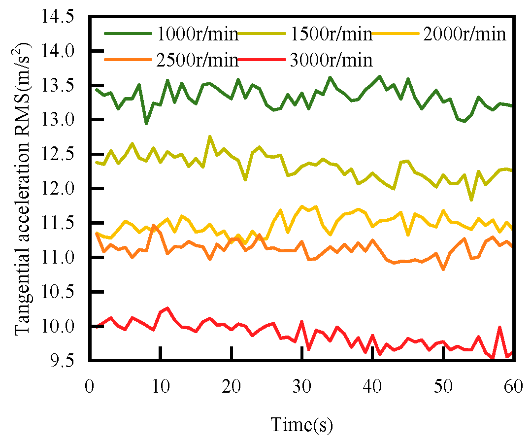
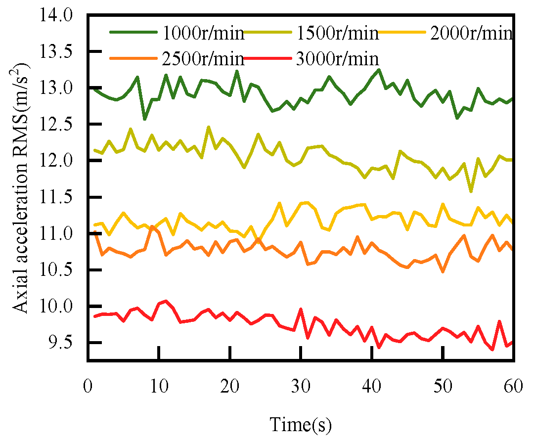
The RMS data collected in the test of Section 3.2.2 were calculated. Figure 23, Figure 24 and Figure 25 show the variation patterns of the RMS of the radial, tangential, and axial acceleration of the mechanical seal face between 1000 r/min and 3000 r/min, respectively.
It can be clearly observed that in the three directions of axial, radial, and tangential, the RMS gradually decreases as the spindle speed increases. Specifically, in the radial direction, as the rotational speed increases from 1000 r/min to 3000 r/min, the RMS gradually decreases from approximately 13.5 m/s2 to approximately 10.5 m/s2. Similarly, in the tangential direction, the RMS also drops from approximately 13.5 m/s2 to approximately 10.0 m/s2. In the axial direction, the RMS is reduced from approximately 13.0 m/s2 to approximately 9.8 m/s2. These data clearly show that there is a clear inverse relationship between the RMS and the rotational speed in all directions examined. In other words, as the rotational speed increases, the vibration of the mechanical seal tends to be stable, and the RMS decreases accordingly.
As the rotational speed increases, the distribution of the lubricant film on the sealing surface becomes more uniform. A uniform oil film reduces direct contact between the friction surfaces, thereby lowering the friction coefficient and friction force. Since the action of the lubricant film is comprehensive, the friction and vibration in the axial, radial, and tangential directions are correspondingly reduced, leading to a decrease in the root mean square value of acceleration.
When the rotational speed increases, the friction heat causes the temperature of the lubricant to rise, reducing its viscosity and improving lubrication effectiveness. The decrease in lubricant viscosity helps form a more stable oil film, reducing the friction force between the friction surfaces. This change in viscosity similarly affects vibrations in all directions; thus, the root mean square value of acceleration decreases in the axial, radial, and tangential directions.
As the rotational speed increases, the contact conditions of the sealing surfaces in different directions tend to become consistent. At high rotational speeds, the dynamic response of the sealing surfaces becomes more uniform, making the friction and vibration characteristics in all directions similar. This consistency leads to a similar trend in the root mean square value of acceleration in the axial, radial, and tangential directions.
Many mechanical seal structures and materials are designed and manufactured with isotropy in mind, meaning they have similar physical and mechanical properties in different directions. At high rotational speeds, this isotropic characteristic becomes more pronounced, making the vibration response in the axial, radial, and tangential directions more uniform, and resulting in a similar trend in the root mean square value of acceleration.
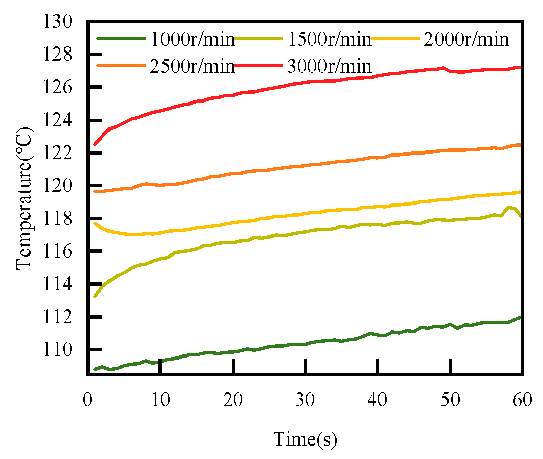
Figure 26 shows the relationship between temperature and rotational speed. As the rotational speed increases, the face temperature increases. Under the working condition of 1000 r/min, the face temperature rises from 108 °C to 111 °C within 1 min; under the working condition of 1500 r/min, the face temperature rises from 113 °C to 117 °C; under the working condition of 2000 r/min, the face temperature rises from 117 °C to 119 °C; under the working condition of 2500 r/min, the face temperature rises from 119 °C to 122 °C; and under the working condition of 3000 r/min, the face temperature rises from 122 °C to 127 °C. The face temperature increases almost linearly with an increase in rotation speed. The reason is that under mixed lubrication conditions, when the rotational speed is higher, the vibration excitation caused by viscous friction is greater. The contact between the liquid film and the asperities between the faces results in higher energy release efficiency under higher-speed viscous shear. This leads to an increase in shear heat and stirring heat between faces, which in turn leads to an upward trend in face temperature. The problem that the face temperature rises by about 3 °C under the same rotation speed is due to the low heat transfer efficiency of the mechanical seal cooling system in the laboratory. When the lubricating oil circulates in the system for a single time, the cooling water cannot reduce the face friction. Therefore, all the heat is taken away, causing the face temperature to show a linear upward trend when the rotation speed is stable.
To sum up, under the condition that the medium pressure is 1.6 MPa, as the rotational speed increases from 1000 r/min to 3000 r/min, the RMS decreases, and the face temperature increases.

4.3. The RMS of the Face Vibration Acceleration Change Law with the Sealing Medium Pressure

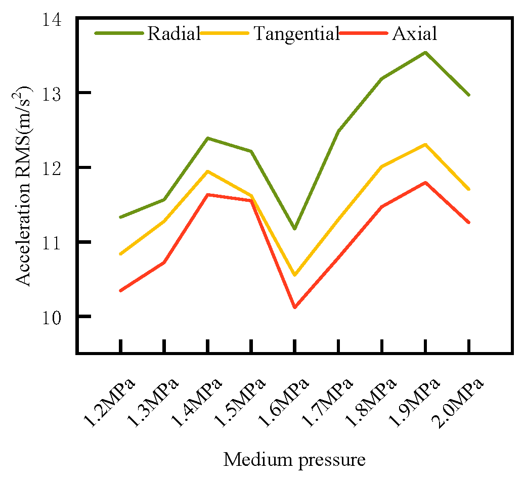
Calculate the RMS data collected in the test of Section 3.2.3. In order to facilitate comparative analysis, calculate the average RMS within 1 min under each pressure gradient and explore the change pattern of the face vibration acceleration RMS with the medium pressure, as shown in Figure 27.
As shown in Figure 27, the RMS first increases and then decreases as the medium pressure increases from 1.2 MPa to 2.0 MPa, and then increases again, showing an “M” shape. This article calculates the average value of the RMS within 60 s of seal operation under the corresponding pressure, in order to observe its changing pattern more intuitively. When the medium pressure rises from 1.2 MPa to 1.4 MPa, the RMS of the radial, tangential, and axial directions show a linear upward trend with an increase in medium pressure; when the medium pressure rises from 1.4 MPa to 1.6 MPa, the RMS of the radial, tangential and axial directions decrease with an increase in medium pressure; when the medium pressure increases from 1.6 MPa to 1.9 MPa, the RMS of the radial, tangential, and axial directions increases; and when the medium pressure increase from 1.9 MPa increases to 2.0 MPa, the RMS of the radial, tangential, and axial directions decrease. Among them, the RMS in the radial direction is the largest, the RMS in the tangential direction is slightly greater than that in the axial direction, and in each direction, the RMS is the smallest under the medium pressure condition of 1.6 MPa.
In general, the literature [5] has demonstrated that contact load is linearly proportional to seal pressure. The reason for the test results is analyzed as follows: at low pressure, that is, below 1.5 MPa, the RMS increases with an increase in fluid medium pressure. This stage corresponds to the initial stage of the mixed lubrication stage of the Stribeck curve. In this stage, due to the low medium pressure, the face opening force is small, the sealing surface specific load is small, the friction coefficient is large, and the RMS increases with an increase in the medium pressure; under the conditions of a medium pressure of 1.5 MPa and 1.6 MPa, as the fluid medium pressure increases, the RMS decreases. This stage corresponds to the stage before the turning point of the Stribeck curve transition from the mixed lubrication regime to the hydrodynamic lubrication regime. The friction coefficient in this regime is small, and the friction coefficient decreases with an increase in medium pressure. So, the RMS also decreases with an increase in medium pressure; when the medium pressure is higher than 1.6 MPa, the RMS increases with an increase in fluid medium pressure. This stage corresponds to the critical point area of the Stribeck curve boundary lubrication and mixed lubrication regimes. As the medium pressure increases, the friction coefficient increases and the RMS increases; when the medium pressure is greater than 1.9 MPa, due to the excessive medium pressure, the specific load of the sealing surface increases, and the friction coefficient decreases with an increase in medium pressure. At this time, the RMS also decreases with an increase in medium pressure.
The reason why RMS shows an “M” trend with the change in medium pressure can be attributed to the change in sealing surface specific load caused by medium pressure. At a lower medium pressure (about 1.2 MPa), the friction coefficient is higher, and the RMS value is also increased due to the direct contact of the surface asperities due to the insufficient formation of the lubricating film. However, as the pressure increases, the lubricating film gradually becomes stable and uniform, the friction coefficient begins to decrease, and the RMS value also decreases. This stage can be considered as the transition from boundary lubrication to mixed lubrication.
However, when the pressure further increases to a certain critical value (about 1.6 MPa to 1.8 MPa), the lubricating film may be squeezed or broken due to excessive pressure, resulting in the friction coefficient increasing again and the RMS value increasing. This phenomenon can correspond to the mixed lubrication region in the Stribeck curve, reflecting the complex changes in the friction coefficient under different lubrication conditions.
In addition, the specific load on the sealing surface may also lead to nonlinear friction behavior by affecting the micro-contact area and the thickness of the lubricating film. For example, under high pressure, due to the compression of surface asperities, the actual contact area increases, which may further aggravate friction and vibration. A change in temperature may also play an important role in it, because an increase in temperature will reduce the viscosity of lubricating oil, which makes the lubricating film easier to break, and then affects the change in the friction coefficient and RMS value.
In summary, the “M” type change trend in RMS is not only related to the change in specific load but also closely related to the transition of lubrication state. This phenomenon is well reflected in the Stribeck curve, which shows that the friction coefficient and vibration characteristics are affected by multiple factors in the mechanical seal system. In practical applications, understanding these complex interactions is of great significance for optimizing seal design and operating parameters.
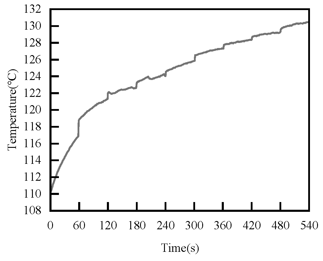
As shown in Figure 28, for the relationship between temperature and medium pressure, as the medium pressure increases, the face temperature increases. Under the working condition of 1.2 MPa, the face temperature rises from 110 °C to 116 °C within 1 min; under the working condition of 1.3 MPa, the face temperature rises from 119 °C to 121 °C; under the working condition of 1.4 MPa, the face temperature rises from 122 °C to 122 °C; under the 1.5 MPa working condition, the face temperature is around 124 °C; under the 1.6 MPa working condition, the face temperature is around 125 °C; under the 1.7 MPa working condition, the face temperature is around 127 °C; under the 1.8 MPa working condition, the face temperature is around 128 °C; under the 1.9 MPa working condition, the face temperature is around 129 °C; and under the 2.0 MPa working condition, the face temperature is around 130 °C. As the medium pressure increases, the face temperature first rises rapidly, and then rises slowly, almost linearly. The reason is that under mixed lubrication conditions, when the medium pressure is high, the friction heat caused by viscous friction still exists, and the resulting pressure heating effect causes the face temperature to increase. In addition, the friction heat generated by fluid friction also increases, resulting in an upward trend in face temperature.
To sum up, when the rotation speed is stable at 3000 r/min, as the medium pressure increases from 1.2 MPa to 2.0 MPa, the RMS of the vibration acceleration of the mechanical seal face changes nonlinearly in an “M” shape, that is, it rises in the range of 1.2–1.4 MPa. The value rises, falls in the range of 1.4–1.6 MPa, reaches the lowest point when it reaches 1.6 MPa, then rises again in the range of 1.6–1.9 MPa, and finally falls again in the range of 1.9–2.0 MPa. In addition, the face temperature increases with an increase in medium pressure.

4.4. RMS of Face Vibration Acceleration Change Law with Surface Roughness

Calculate the RMS data collected in the test of Section 3.2.3, as shown in Figure 29, Figure 30 and Figure 31.
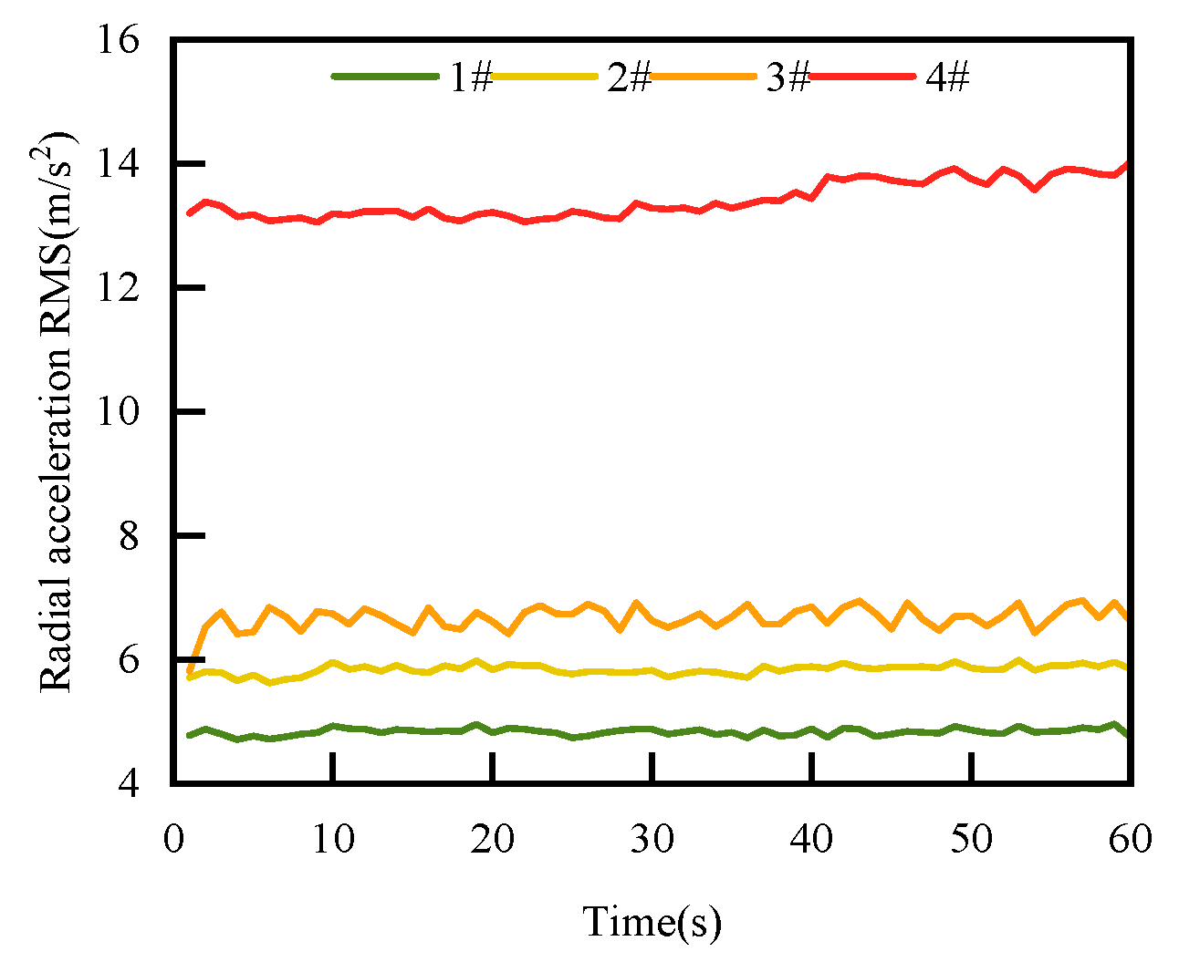
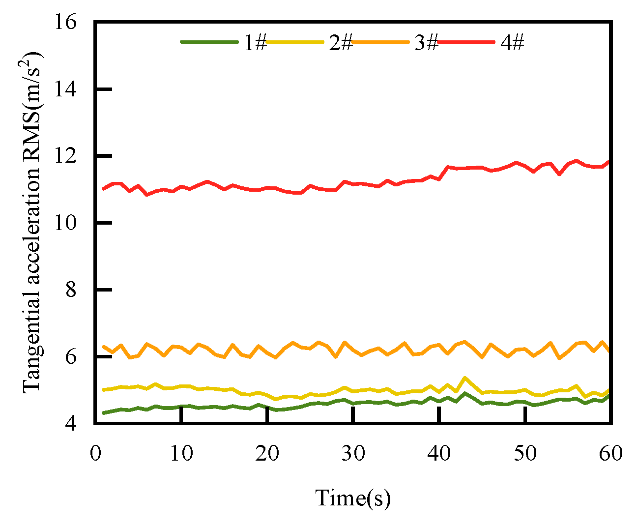
The RMS increases with an increase in surface roughness. When the mechanical seal replaces the 4# rotating ring, that is, when the face surface roughness exceeds the standard 0.2 μm, the RMS increases significantly. As shown in Figure 25, Figure 26 and Figure 27, the RMS of the corresponding faces of the 1#, 2#, 2#, and 4# rotating rings in the radial, tangential, and axial directions is compared, respectively.
In the radial direction, the RMS of the 1# rotating ring is 4.5 m/s2, and when the large 4# rotating ring is replaced, the RMS rises to 13.3 m/s2. In the tangential direction, the RMS of the 1# rotating ring is 4.2 m/s2, and when it is replaced with the 4# rotating ring, the RMS rises to 11.0 m/s2. In the axial direction, the RMS of the 1# rotating ring test is 4.5 m/s2, while the RMS of the 4# rotating ring test rises to 12.0 m/s2. The test data show that in the three directions of axial, radial, and tangential, the RMS is proportional to the surface roughness. When the face quality does not meet the working condition requirements, that is, when failure occurs, the RMS changes sharply, with increments exceeding 5 m/s2. This phenomenon shows that surface roughness has a significant impact on the vibration performance of mechanical seals.
When the surface roughness of the mechanical seal friction pair increases from 0.07 μm to 0.32 μm, the number of micro-protrusions on the face of the mechanical seal increases, the number of direct contact rough bodies increases, and the RMS increases with an increase in surface roughness.
The RMS value of the vibration acceleration of the mechanical seal end face increases with an increase in the surface roughness, which is reflected in the RMS values of the axial, radial, and tangential accelerations. From a tribological point of view, an increase in surface roughness leads to an increase in the number of asperities on the contact surface, thereby expanding the actual contact area, increasing the friction force, and thus enhancing the vibration in all directions. This phenomenon can be further explained by the Hertz contact theory in contact mechanics, indicating how the plastic deformation of the asperity and the change in the microstructure of the material surface aggravate the increase in friction with the increase in contact stress.
On the lubricating surface, the rough surface makes the lubricating oil film easier to break. This process will lead to the instantaneous failure of the oil film through the local high-pressure zone, thus increasing the direct contact between the surfaces of the friction pairs. The rupture and reconstruction process of the lubricating oil film may be periodic, which further leads to the nonlinear enhancement of vibration. Especially under high-temperature conditions, the viscosity of the lubricating oil decreases, and the stability of the oil film weakens, making the amplitude of the vibration signal more significant.
In addition, an increase in surface roughness also changes the stiffness and damping characteristics of the mechanical system. Especially under high-frequency vibration, surface roughness may cause resonance phenomena, resulting in severe vibration fluctuations. This change not only affects the amplitude of the vibration but may also affect the fatigue life of the system. By introducing numerical simulation and analysis of experimental data, it can be seen that the influence of different roughness on vibration characteristics is nonlinear, which is consistent with the isotropic vibration enhancement phenomenon.
On the whole, the influence of an increase in surface roughness on the mechanical seal is not only limited to the vibration enhancement but may also cause a series of problems such as material wear and seal failure. Therefore, understanding and controlling surface roughness is of great significance for optimizing the performance of mechanical seals and prolonging the service life of equipment. This also provides a direction for future research, that is, by improving surface treatment technology or developing new lubricating materials to reduce the adverse effects of high roughness on the system.
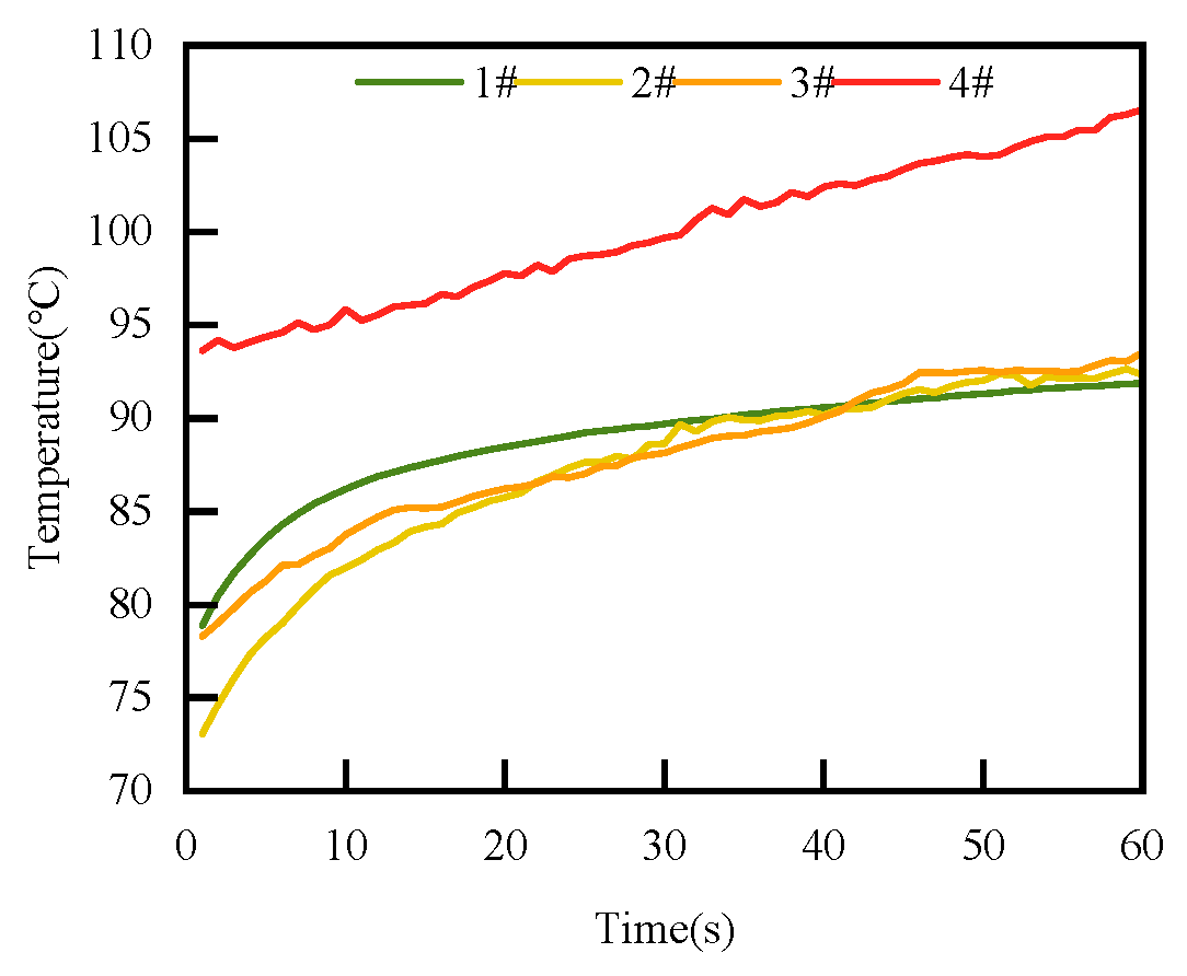
Figure 32 shows the relationship between the face temperature and the surface roughness. It can be seen from the figure that at the beginning of the test for the 1#, 2#, and 3# rotating ring tests, the face temperature range was 70~80 °C. At the end, the temperatures were all 90 °C. When the surface roughness value was lower than the allowable value stipulated in the standard, there was no significant difference in the face temperature; when the face surface roughness exceeded the allowable value and the face quality dropped too much, that is, during the 4# the rotating ring test, the face temperature increased significantly, with the highest temperature reaching 105 °C. The reasons include the following three points: As the number of rough bodies on the face increases, the roughness collision increases, resulting in an increase in the pressure per unit area, which causes an increase in local friction and heat, thereby increasing the face temperature. Increased surface roughness leads to poorer lubrication conditions, increasing frictional resistance, and generating more frictional heat. The increase in surface roughness leads to uneven stress distribution and local pressure concentration in the contact area, thereby increasing friction and wear, further causing an increase in face surface temperature.
To sum up, under the conditions of a medium pressure of 1.6 MPa and a rotation speed of 3000 r/min, as the surface roughness of the rotating ring face increases from 0.07 μm to 0.32 μm, the irregularity of the contact area on the surface of the mechanical seal and the increase in the number of asperities lead to increased friction and wear. Consequently, the RMS of the vibration acceleration of the mechanical seal face also increases. Additionally, the face temperature increases.

5. Conclusions

Aiming at the lack of effective condition monitoring methods for mechanical seals, a new method is proposed to characterize the tribological regime of mechanical seals by using the face vibration acceleration parameters. In order to verify the validity of the proposed method, the proposed method of face vibration acceleration measurement is analyzed through theoretical analysis and experimental research.
The main work of this paper is as follows:
  • A method for measuring the tribological behavior of mechanical seals by the face vibration acceleration is proposed and applied to the test rig.
  • A tribological behavior model of mechanical seals based on micro-convex contact and viscous shear is established, and the relationship between face acceleration RMS and tribological behavior parameters is clarified, providing theoretical sources for the method.
  • This experimental study shows that the face tribological regime changes during the start and stop stages of the mechanical seal, and the change in the RMS curve is consistent with the changing trend in the Stribeck curve, which further proves the effectiveness of the proposed method.
  • According to the experimental study, an increase in speed will lead to a decrease in the RMS value, an increase in sealing medium pressure will lead to a nonlinear change in RMS, and an increase in surface roughness will lead to an increase in RMS.
This research provides a theoretical basis for the realization of condition monitoring of mechanical seals, enriching the field of mechanical seal monitoring methods and offering technical guidance for predictive maintenance in mechanical seal engineering.

Author Contributions

Conceptualization, Y.S. and Q.W.; methodology, Y.S.; validation, W.X.; writing—original draft preparation, Y.S.; writing—review and editing, Q.W.; visualization, H.L.; supervision, S.L. All authors have read and agreed to the published version of the manuscript.

Funding

This research was funded by the PipeChina Institute of Science and Technology Project, grant number CLZB202202, and National Pipe Network Group United Pipeline Co., Ltd., Western Branch Project, grant number WZXGL202107.

Data Availability Statement

Since much of the content in this paper is part of the team’s ongoing research about seals, the relevant data cannot be shared at the time of publication.

Conflicts of Interest

Authors Hua Li and Wang Xiao were employed by the National Oil and Gas Pipeline Network Group Co., Ltd. The remaining authors declare that the research was conducted in the absence of any commercial or financial relationships that could be construed as a potential conflict of interest.

Abbreviations

RMSRoot mean square
BLBoundary lubrication
MLMixed lubrication
HLHydrodynamic lubrication
F Friction force
τ a a The shear stress in the asperity–asperity (a-a) interaction
F a a The friction force acting on the free face of each equivalent asperity
U i The vibration energy
σ b The bending stress
M The bending moment
U i ( a a ) The vibration energy leading to asperity–asperity (a-a) interaction
U ¯ i ( a a ) The average energy leading to asperity–asperity (a-a) interaction
U V The total vibration energy
U V ( a a ) The total vibration energy
U ˙ V ( a a ) The vibration energy generation rate
V r m s ( a a ) The relationship between the RMS of vibration and vibration energy
U1The first face’s x-direction velocity vector
V1The first face’s y-direction velocity vector
W1The first face’s z-direction velocity vector
U2The second face’s x-direction velocity vector
V2The second face’s y-direction velocity vector
W2The second face’s z-direction velocity vector
u ( x , y , z ) The velocity vector of fluid film in the x-direction
v ( x , y , z ) The velocity vector of fluid film in the y-direction
w ( x , y , z ) The velocity vector of fluid film in the z-direction
ρ ( x , y , z ) The density of the fluid
μ ( x , y , z ) The dynamic viscosity of the fluid
W The total load-bearing capacity resulting from fluid pressure and contact pressure
p m The contact pressure
b m The fraction of the total area of the contact area
F f The total circumferential friction force
F m The tangential contact friction force
τ m The contact friction stress
F The total friction caused by viscous shear and contact friction
q θ The radial flow rate of the fluid
q r The circumferential flow rate of the fluid
V θ The volume of fluid along the radial direction
V r The volume of fluid along the circumferential direction
a z The axial face acceleration
a y The radial face acceleration
a x The circumferential face acceleration

References

  1. Meng, X.; Tu, Z.; Ma, Y.; Jiang, J.; Peng, X. Topology optimization of liquid lubricating zero-leakage mechanical face seals. Tribol. Int. 2022, 169, 107490. [Google Scholar] [CrossRef]
  2. Jamari, J. Running-In of Rolling Contacts. Ph.D. Thesis, University of Twente, Enschede, The Netherlands, 2006. [Google Scholar]
  3. Towsyfyan, H.; Gu, F.; Ball, A.D.; Liang, B. Modelling acoustic emissions generated by tribological behaviour of mechanical seals for condition monitoring and fault detection. Tribol. Int. 2018, 125, 46–58. [Google Scholar] [CrossRef]
  4. Lebeck, A.O. Principles and Design of Mechanical Face Seals; Wiley: Hoboken, NJ, USA, 1991. [Google Scholar]
  5. Towsyfyan, H. Investigation of the Nonlinear Tribological Behaviour of Mechanical Seals for Online Condition Monitoring. Doctoral Dissertation, University of Huddersfield, Huddersfield, UK, 2018. [Google Scholar]
  6. Gani, M.; Santos, I.F.; Arghir, M.; Grann, H. Model validation of mechanical face seals in two-phase flow conditions. Tribol. Int. 2022, 167, 107417. [Google Scholar] [CrossRef]
  7. Li, Q.-P.; Zhang, J.-Y.; Zhang, J.-X.; Zhang, Y.-X. Influence of pressure disturbance wave on dynamic response characteristics of liquid film seal for multiphase pump. Pet. Sci. 2024, 21, 2048–2065. [Google Scholar] [CrossRef]
  8. Yu, B.; Hao, M.; Xinhui, S.; Wang, Z.; Fuyu, L.; Yongfan, L. Analysis of dynamic characteristics of spiral groove liquid film seal under thermal–fluid–solid coupling. Ind. Lubr. Tribol. 2021, 73, 882–890. [Google Scholar] [CrossRef]
  9. Huang, W.; Liao, C.; Liu, X.; Suo, S.; Liu, Y.; Wang, Y. Thermal fluid-solid interaction model and experimental validation for hydrostatic mechanical face seals. Chin. J. Mech. Eng. 2014, 27, 949–957. [Google Scholar] [CrossRef]
  10. Liu, X.; Peng, X.D.; Meng, X.K. Thermo-elasto-hydrostatic effect analysis of the double tapered hydrostatic mechanical seals for reactor coolant pumps under the influence of flow regime. In Proceedings of the 2012 Asia-Pacific Power and Energy Engineering Conference, Shanghai, China, 27–29 March 2012; pp. 1–6. [Google Scholar]
  11. Zhou, X.; Chen, Z.; Gu, C.; Wang, J. Thermo-mechanical coupling analysis of the end faces for a mechanical seal under dry friction. Tribol. Int. 2021, 160, 107050. [Google Scholar] [CrossRef]
  12. Ni, X.; Sun, J.; Ma, C.; Zhang, Y. Wear Model of a Mechanical Seal Based on Piecewise Fractal Theory. Fractal Fract. 2023, 7, 251. [Google Scholar] [CrossRef]
  13. Li, X.; Yang, Z.; Xu, J.; Chen, R.; Yang, H. The fractal leakage model of contact mechanical seals considering wear and thermal deformation. J. Braz. Soc. Mech. Sci. Eng. 2019, 41, 521. [Google Scholar] [CrossRef]
  14. Ni, X.; Ma, C.; Sun, J.; Zhang, Y.; Yu, Q. A leakage model of contact mechanical seals based on the fractal theory of porous medium. Coatings 2021, 11, 20. [Google Scholar] [CrossRef]
  15. Zheng, W.; Sun, J.; Ma, C.; Yu, Q. Interface leakage theory of mechanical seals considering microscopic forces. Coatings 2023, 13, 1435. [Google Scholar] [CrossRef]
  16. Sinou, J.J.; Cayer-Barrioz, J.; Berro, H. Friction-induced vibration of a lubricated mechanical system. Tribol. Int. 2013, 61, 156–168. [Google Scholar] [CrossRef]
  17. Akay, A. Acoustics of friction. J. Acoust. Soc. Am. 2002, 111, 1525–1548. [Google Scholar] [CrossRef]
  18. Sharma, R.B.; Parey, A. Modelling of acoustic emission generated in rolling element bearing. Appl. Acoust. 2019, 144, 96–112. [Google Scholar] [CrossRef]
  19. Kaya, S.; Yilan, F.; Urtekin, L. Influences of Cr on the microstructural, wear and mechanical performance of high-chromium white cast iron grinding balls. SAE Int. J. Mater. Manuf. 2023, 1, 23–30. [Google Scholar] [CrossRef]
  20. Köse, R.; Urtekin, L.; Ceylan, A.; Salman, S.; Findik, F. Three types of ceramic coating applicability in automotive industry for wear resistance purpose. Ind. Lubr. Tribol. 2005, 57, 140–144. [Google Scholar] [CrossRef]
  21. Mousavi, S.B.; Heris, S.Z.; Estellé, P. Experimental comparison between ZnO and MoS2 nanoparticles as additives on performance of diesel oil-based nano lubricant. Sci. Rep. 2020, 10, 5813. [Google Scholar] [CrossRef]
  22. Mousavi, S.B.; Pourpasha, H.; Heris, S.Z. High-temperature lubricity and physicochemical behaviors of synthesized Cu/TiO2/MnO2-doped GO nanocomposite in high-viscosity index synthetic biodegradable PAO oil. Int. Commun. Heat Mass Transf. 2024, 156, 107642. [Google Scholar] [CrossRef]
  23. Mousavi, S.B.; Zeinali Heris, S.; Hosseini, M.G. Experimental investigation of MoS2/diesel oil nanofluid thermophysical and rheological properties. Int. Commun. Heat Mass Transf. 2019, 108, 104298. [Google Scholar] [CrossRef]
  24. Mousavi, S.B.; Zeinali Heris, S.; Estellé, P. Viscosity, tribological and physicochemical features of ZnO and MoS2 diesel oil-based nanofluids: An experimental study. Fuel 2021, 293, 120481. [Google Scholar] [CrossRef]
  25. Aghaei Sarvari, A.; Zeinali Heris, S.; Mohammadpourfard, M.; Mousavi, S.B.; Estellé, P. Numerical investigation of TiO2 and MWCNTs turbine meter oil nanofluids: Flow and hydrodynamic properties. Fuel 2022, 320, 123943. [Google Scholar] [CrossRef]
  26. Zhang, E.Q.; Fu, P.; Li, K.; Li, X.; Zhou, Z. Film thickness measurement of mechanical seal based on cascaded artificial neural network recognition model. Int. J. Smart Sens. Intell. Syst. 2014, 7, 1870–1889. [Google Scholar] [CrossRef]
  27. Huang, D.; Yan, X.; Larsson, R.; Almqvist, A. Numerical simulation of static seal contact mechanics including hydrostatic load at the contacting interface. Lubricants 2021, 9, 1. [Google Scholar] [CrossRef]
  28. Luo, Y.; Zhang, W.; Fan, Y.; Han, Y.; Li, W.; Acheaw, E. Analysis of vibration characteristics of centrifugal pump mechanical seal under wear and damage degree. Shock Vib. 2021, 2021, 6670741. [Google Scholar] [CrossRef]
  29. Wang, Q.; Song, Y.; Li, H.; Shu, Y.; Xiao, Y. Tribological behavior characterization and fault detection of mechanical seals based on face vibration acceleration measurements. Lubricants 2023, 11, 430. [Google Scholar] [CrossRef]
  30. Dowson, D. A generalized Reynolds equation for fluid-film lubrication. Int. J. Mech. Sci. 1962, 4, 159–170. [Google Scholar] [CrossRef]
  31. Wang, S.T.; Wu, O.Y.; Li, Z.; Wang, B. Load carrying capacity of a novel magnetic-liquid double suspension fixed pad thrust bearing. Ind. Lubr. Tribol. 2021, 73, 381–387. [Google Scholar] [CrossRef]
  32. Greenwood, J.; Williamson, J. Contact of nominally flat surfaces. Proc. R. Soc. Lond. (A) 1966, 295, 300–319. [Google Scholar] [CrossRef]
  33. Persson, B.N.J. Contact mechanics for randomly rough surfaces. Surf. Sci. Rep. 2006, 61, 201–227. [Google Scholar] [CrossRef]
  34. Lin, Z.; Sayer, P. Influence of water depth variation on the hydrodynamics of deep-water mooring characteristics. Ocean Eng. 2015, 109, 553–566. [Google Scholar] [CrossRef]
  35. Gross, D.; Ehlers, W.; Wriggers, P.; Schröder, J.; Müller, R. Mechanics of Materials–Formulas and Problems; Springer: Berlin/Heidelberg, Germany, 2017. [Google Scholar]
  36. Hurtado, J.A.; Kim, K.S. Scale effects in friction of single–asperity contacts. II. Multiple–dislocation–cooperated slip. Proc. R. Soc. A Math. Phys. Eng. Sci. 1999, 455, 3363–3384. [Google Scholar] [CrossRef]
  37. Hibbeler, R. Mechanics of Materials; SI Edition; Pearson Schweiz: Amsterdam, The Netherlands, 2013. [Google Scholar]
  38. Archard, J.F. Contact and rubbing of flat surfaces. J. Appl. Phys. 1953, 24, 981–988. [Google Scholar] [CrossRef]
  39. Ibrahim, R.A. Friction-induced vibration, chatter, squeal, and chaos—Part I: Mechanics of contact and friction. Appl. Mech. Rev. 1994, 47, 227. [Google Scholar] [CrossRef]
  40. MIL-PRF-23699F; Performance Specification: Lubricating Oil, Aircraft Turbine Engine, Synthetic Base, Nato Code Number O-156. United States Military Standard: Washington, DC, USA, 1997.
  41. Liu, X.; Xia, J.; Zhou, M.; Deng, S.; Li, Z. A new formula for predicting movable bed roughness coefficient in the Middle Yangtze River. Progr. Phys. Geogr. Earth Environ. 2022, 46, 441–457. [Google Scholar] [CrossRef]
  42. JB/T 4127.1-2013; Mechanical Seals Part 1: Technical Conditions. Ministry of Industry and Information Technology: Beijing, China, 2013.
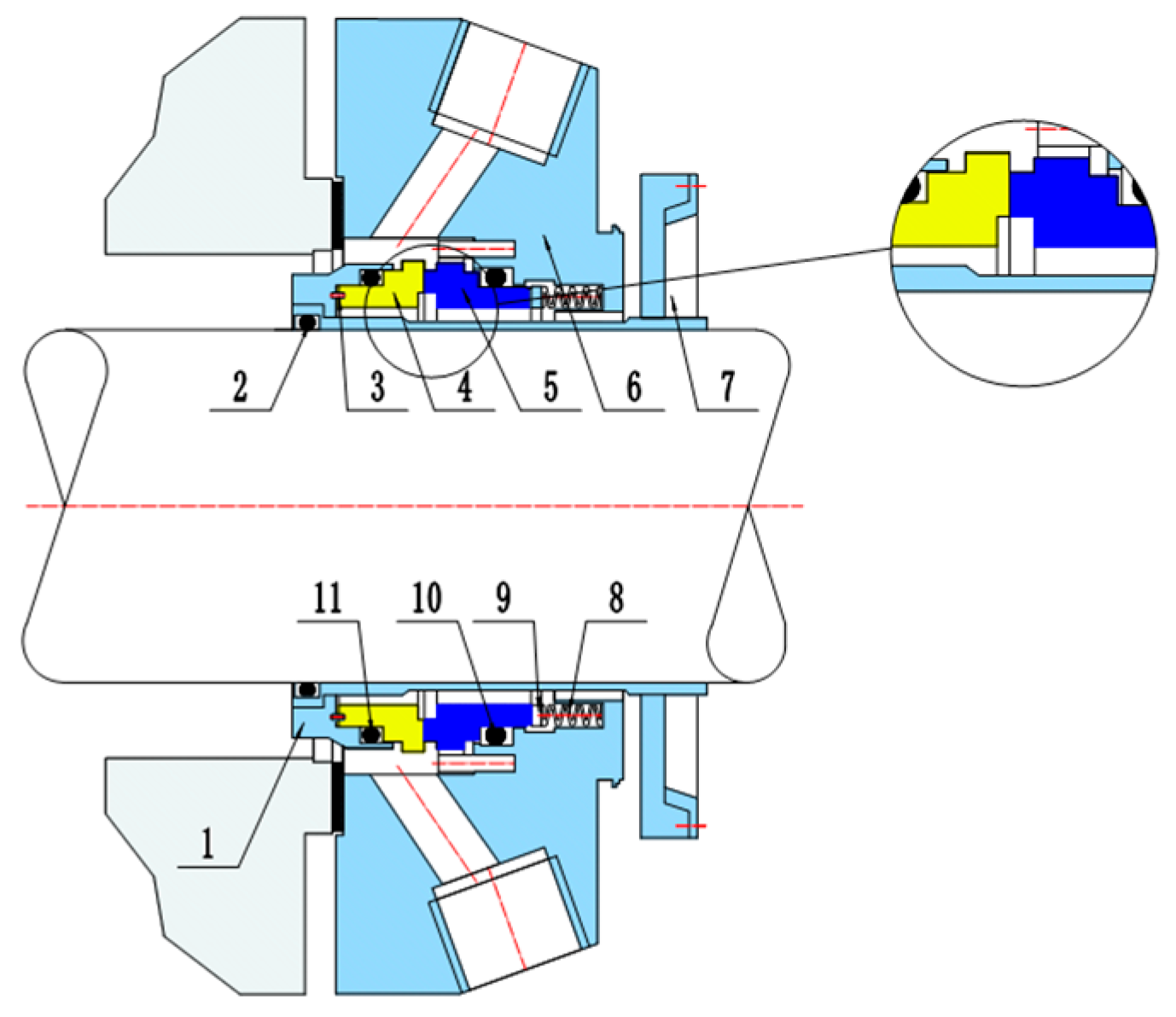
Figure 1. Mechanical seal structure.
Lubricants 12 00316 g001
Figure 2. Stribeck curve.
Lubricants 12 00316 g002
Figure 3. The face control body in Cartesian coordinates.
Lubricants 12 00316 g003
Figure 4. The Greenwood and Williamson model for contact.
Lubricants 12 00316 g004
Figure 5. Tribological behavior test rig of mechanical seal.
Lubricants 12 00316 g005
Figure 6. Tribological behavior test rig of mechanical seal assembly schematic diagram.
Lubricants 12 00316 g006
Figure 7. Tribological behavior test rig of mechanical seal assembly physical diagram.
Lubricants 12 00316 g007
Figure 8. Installation diagram of thermocouple temperature sensor.
Lubricants 12 00316 g008
Figure 9. Mechanical seal with sensor.
Lubricants 12 00316 g009
Figure 10. Lubrication and cooling system.
Lubricants 12 00316 g010
Figure 11. Rotating ring 1# exterior diagram.
Lubricants 12 00316 g011
Figure 12. Rotating ring 2# exterior diagram.
Lubricants 12 00316 g012
Figure 13. Rotating ring 3# exterior diagram.
Lubricants 12 00316 g013
Figure 14. Rotating ring 4# exterior diagram.
Lubricants 12 00316 g014
Figure 15. Rotating ring 1# surface diagram.
Lubricants 12 00316 g015
Figure 16. Rotating ring 2# surface diagram.
Lubricants 12 00316 g016
Figure 17. Rotating ring 3# surface diagram.
Lubricants 12 00316 g017
Figure 18. Rotating ring 4# surface diagram.
Lubricants 12 00316 g018
Figure 19. Radial acceleration RMS start–stop phase change curve.
Lubricants 12 00316 g019
Figure 20. Tangential acceleration RMS start–stop phase change curve.
Lubricants 12 00316 g020
Figure 21. Axial acceleration RMS start–stop phase change curve.
Lubricants 12 00316 g021
Figure 22. Change curve of face temperature in start–stop stage.
Lubricants 12 00316 g022
Figure 23. Relationship between radial RMS and rotational speed.
Lubricants 12 00316 g023
Figure 24. Relationship between tangential RMS and rotational speed.
Lubricants 12 00316 g024
Figure 25. Relationship between axial RMS and rotational speed.
Lubricants 12 00316 g025
Figure 26. Relationship between temperature and rotational speed.
Lubricants 12 00316 g026
Figure 27. Curve of acceleration RMS changing with medium pressure.
Lubricants 12 00316 g027
Figure 28. Curve of face temperature changing with time.
Lubricants 12 00316 g028
Figure 29. The relationship between the RMS of radial acceleration and surface roughness.
Lubricants 12 00316 g029
Figure 30. The relationship between the RMS of tangential acceleration and surface roughness.
Lubricants 12 00316 g030
Figure 31. The relationship between the RMS of axial acceleration and surface roughness.
Lubricants 12 00316 g031
Figure 32. The relationship between face temperature and surface roughness.
Lubricants 12 00316 g032
Table 1. Details of friction pair.
ProjectMaterialYoung’s ModulusPoisson RatioInside
Diameter
Outside
Diameter
Height
Stationary ringSIC475 GPa0.142126 mm137 mm42 mm
Rotating ring27 mm
Table 2. Acceleration sensor parameter table.
ModelPCB 356a03
Sensitivity10 mv/g
Range±500 g
Resolution0.003 g rms
Frequency response range2~5000 Hz
Installation methodBonding
Size6.35 × 6.35 × 6.35 mm
Table 3. Thermocouple sensor parameter table.
ModelPt100
Range−50 °C–400 °C
Precision0.3 °C
Table 4. Physical properties of lubricating oil.
TypeAero Oil
Implementation standardsMIL-PRF-23699 [40]
ComponentSynthetic ester oil (pentaerythritol ester)
Kinematic viscosity at 100 °C5.0 mm2/s
Kinematic viscosity at 40 °C27.6 mm2/s
Kinematic viscosity at −40 °C11,000 mm2/s
Pour point−59 °C
Flash point270 °C
Table 5. Sealing speed change test parameters.
ProjectCondition 1Condition 2Condition 3Condition 4Condition 5
Spindle speed1000 r/min1500 r/min2000 r/min2500 r/min3000 r/min
Inverter frequency17 Hz25 Hz33 Hz42 Hz50 Hz
Pressure1.6 MPa1.6 MPa1.6 MPa1.6 MPa1.6 MPa
Sampling time1 s1 s1 s1 s1 s
Sampling frequency25.6 kHz25.6 kHz25.6 kHz25.6 kHz25.6 kHz
Sampling points25,60025,60025,60025,60025,600
Sampling duration1 min1 min1 min1 min1 min
Face vibration accelerationAxial, radial, tangentialAxial, radial, tangentialAxial, radial, tangentialAxial, radial, tangentialAxial, radial, tangential
Table 6. Sealing medium pressure change test parameters.
ProjectCondition 1Condition 2Condition 3Condition 4Condition 5Condition 6Condition 7Condition 8Condition 9
Pressure1.2 MPa1.3 MPa1.4 MPa1.5 MPa1.6 MPa1.7 MPa1.8 MPa1.9 MPa2.0 MPa
Spindle speed3000 r/min3000 r/min3000 r/min3000 r/min3000 r/min3000 r/min3000 r/min3000 r/min3000 r/min
Sampling time1 s1 s1 s1 s1 s1 s1 s1 s1 s
Sampling frequency25.6 kHz25.6 kHz25.6 kHz25.6 kHz25.6 kHz25.6 kHz25.6 kHz25.6 kHz25.6 kHz
Sampling points25,60025,60025,60025,60025,60025,60025,60025,60025,600
Sampling duration1 min1 min1 min1 min1 min1 min1 min1 min1 min
Face vibration accelerationAxial, radial, tangentialAxial, radial, tangentialAxial, radial, tangentialAxial, radial, tangentialAxial, radial, tangentialAxial, radial, tangentialAxial, radial, tangentialAxial, radial, tangentialAxial, radial, tangential
Table 7. Measurement value of surface roughness of rotating ring.
Rotating Ring NumberSurface Roughness Ra/μm
1#0.07
2#0.09
3#0.20
4#0.32
Table 8. Measurement value of surface roughness of rotating ring.
ProjectCondition 1Condition 2Condition 3Condition 4
Face roughness0.07 μm0.09 μm0.20 μm0.32 μm
Pressure1.6 MPa1.6 MPa1.6 MPa1.6 MPa
Spindle speed3000 r/min3000 r/min3000 r/min3000 r/min
Sampling time1 s1 s1 s1 s
Sampling frequency25.6 kHz25.6 kHz25.6 kHz25.6 kHz
Sampling points25,60025,60025,60025,600
Sampling duration1 min1 min1 min1 min
Face vibration accelerationAxial, radial, tangentialAxial, radial, tangentialAxial, radial, tangentialAxial, radial, tangential
Disclaimer/Publisher’s Note: The statements, opinions and data contained in all publications are solely those of the individual author(s) and contributor(s) and not of MDPI and/or the editor(s). MDPI and/or the editor(s) disclaim responsibility for any injury to people or property resulting from any ideas, methods, instructions or products referred to in the content.