1. Introduction
Parasitic currents and electric discharges have been subject to research for more than a century. Since the early days of electric motor development, the phenomena of shaft voltages and associated bearing damage has been known [
1,
2,
3,
4]. Due to the increased interest in electric drives, this has once again become a focus of research in recent years [
5]. Modern frequency converters with high switching frequencies induce different types of parasitic currents to bearings situated in the motors and gearboxes of electric drivetrains. These currents occur in the form of electric discharge machining (EDM) currents and circular bearing currents [
6,
7].
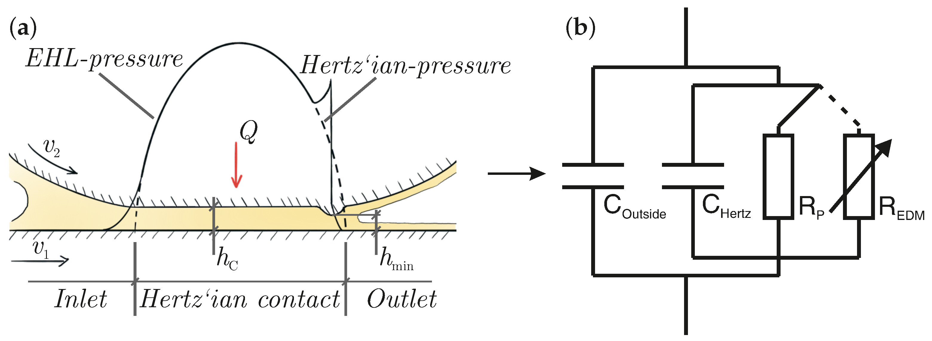
In rolling bearings, the concentrated contact between the rolling element and raceway is usually highly stressed. Together with the the usage of lubricants, a so-called elastohydrodynamically lubricated (EHL) contact is formed, whereby the solid bodies are seperated by a lubricating intermediate medium. A schematic representation of the EHL contact with a typical pressure distribution is shown in
Figure 1a. The electrical characteristics of this contact can be modeled using an equivalent circuit comprising the contact’s capacitance and resistance, as shown in
Figure 1b. The total capacitance includes the Hertz’ian capacitance
from the Hertz’ian contact area and the outside capacitance
from the inlet and outlet zones. Various theoretical models on the capacitance and impedance of rolling bearings have been developed [
8,
9,
10,
11,
12].
In the presence of a separating lubricating film, the parallel resistance
is very high. Once the applied voltage exceeds a specific threshold, a breakdown occurs, leading to a discharge through the substantially lower resistance
, which varies over time.
Tischmacher [
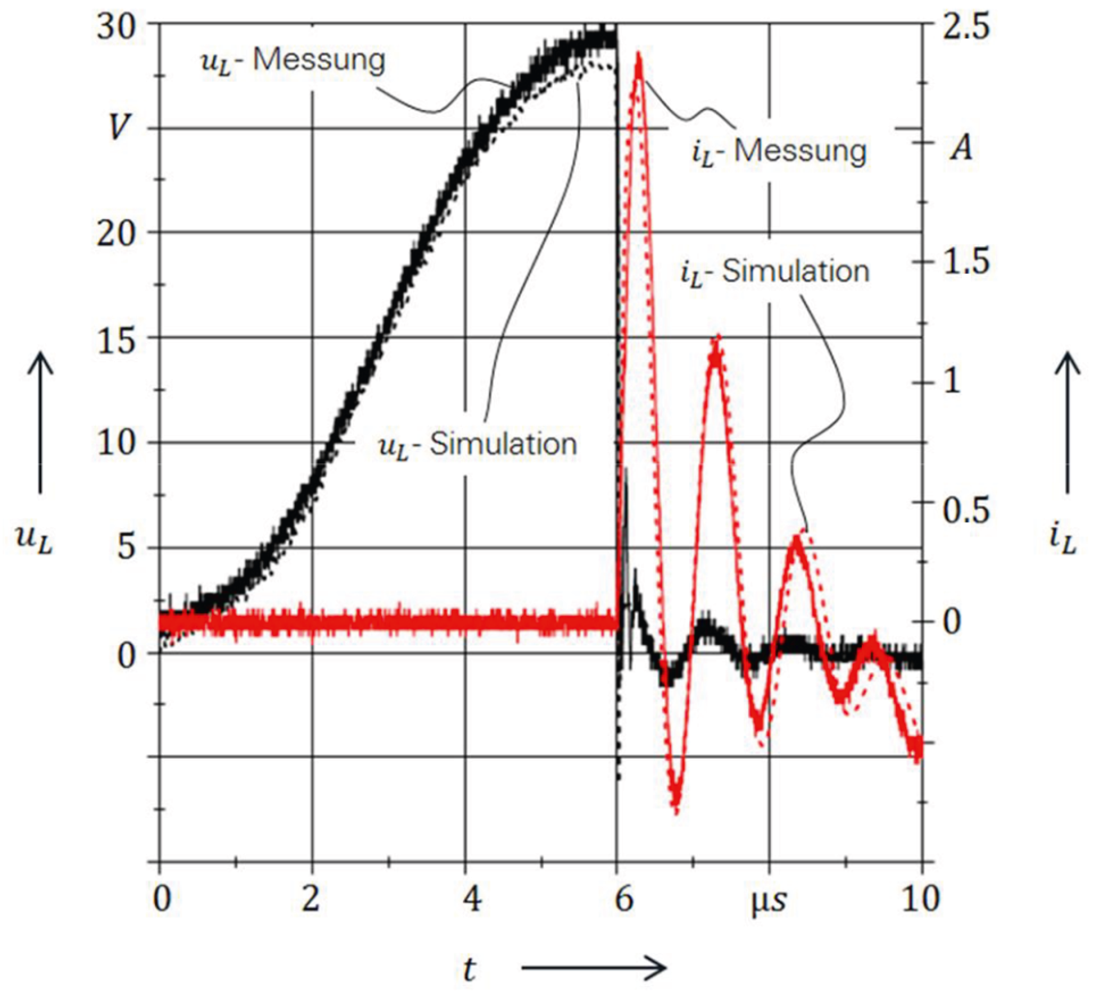
13] simulated and measured these discharges. A typical discharge scenario is displayed in
Figure 2, whereby the voltage continues to rise until it reaches a critical value; in this case, at just under 30 volts. Until this point, the current is relatively constant around zero. Subsequently, as the discharge occurs, an abrupt decline in voltage ensues, together with a rise of the current to a peak of almost 2.5 A. Subsequently, both signals oscillate until they stabilize again.
Depending on the circumstances, these discharges can lead to diverse forms of damage to rolling bearings [
14]. In the case of full-film lubrication, EDM can occur and the temperatures in an arc can peak at up to 3000 K, which not only melts but also vaporizes parts of the material near the surface and has the potential to significantly alter the surface roughness [
15,
16]. As described by Furtmann [
8,
14,
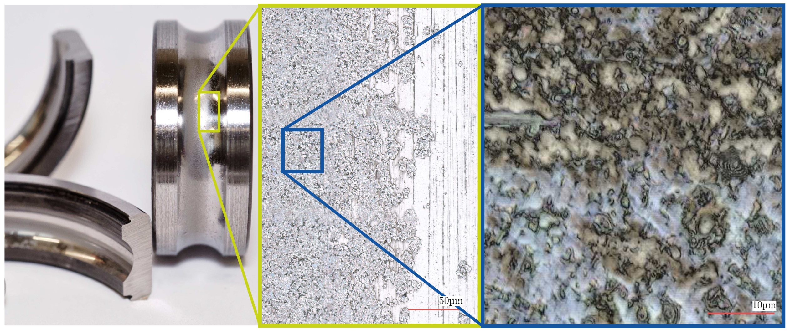
17], the short-term melting with consecutive oil-quenching alternates with repeated over-rollings, creating a “grey frosted” surface. The term refers to the visual appearance of the surface, which, on a macroscopic scale, has similarity to mechanically induced micro pitting. However, there are microscopic differences as the grey frosting shows smoothly flowing edges of the melted areas instead of rough fractures as seen in
Figure 3.
More severe damage, such as fluting, can occur as a result of repeated discharges, leading to increased vibration, accelerated wear, and potential bearing failure. Fluting manifests as alternating lighter and darker areas corresponding to valleys and peaks on the bearing surface [
13]. In addition to surface damage, the lubricant itself can be adversely affected, resulting in degraded performance, such as a reduction in dielectric strength [
18].
While the damage patterns described are well established and have been subject of research for a while, the influence of electrical pre-stress on the service life of rolling bearings has not yet been part of investigations. Therefore, the questions that need to be investigated are, firstly, to what extent does harmful current passage affect the service life of rolling bearings? And secondly, how can this influence be quantified and made predictable? This prompted the initiation of novel experimental investigations, the results of which are presented in this study. The findings led to the development of a new extension to an existing model for calculating the service life of rolling bearings, which now incorporates the impact of electrical currents on service life.
2. Materials and Methods
The primary objective of the experimental investigations was to apply controlled electrical pre-stress to cylindrical rolling bearings and subsequently test their service life without further electrical stress. At first, the influence on the effect of a single steel rolling element in an otherwise hybrid bearing was investigated. After these preliminary studies, the electrical pre-stressing of the bearings took place. Finally, this was followed by the service-life tests themselves. Two test rigs were used for the experimental investigations: the modified universal test rig and four-bearing radial fatigue life test rig, both of which are described below. All bearings underwent a run-in procedure to make sure that the machining marks were flattened [
19] and consistent experimental conditions were maintained during all experimental investigations.
2.1. Test Equipment
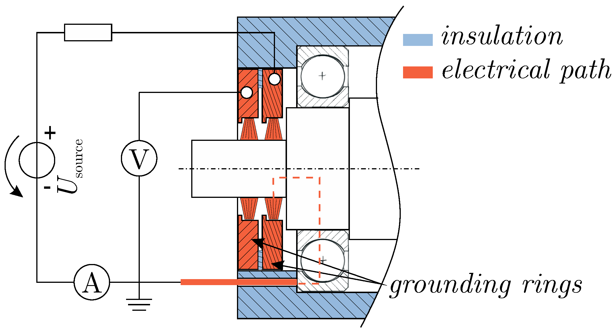
The influence investigations and the induction of controlled electrical pre-stress were conducted using a modified universal bearing test rig. This rig accommodates various bearing types, including cylindrical roller bearings and deep groove ball bearings, under different loading conditions and controlled-temperature environments. Different lubrication methods, such as oil immersion and grease lubrication, can also be used. As shown in
Figure 4, the test head was modified with insulating bearing seats as well as hybrid support bearings with ceramic rolling elements made of zirconium oxide. These measures create a controlled current path through the test bearing, which was equipped with both ceramic elements and a varying number of steel rolling elements. The universal bearing test rig enabled the measurement of frictional torques, shaft speed, temperatures, and mechanical loads of the bearing. It was also possible to measure the capacitance and film thickness as described in [
12,
20].
The voltage application is facilitated by an Aegis shaft grounding ring connected to one of the outputs of the voltage source, thereby applying a potential to the shaft. Contact with the outer ring is established through a spring-loaded aluminum electrode, completing the circuit by connecting back to the voltage source. This configuration ensures a short current path with minimal unwanted losses. To further minimize losses, all cables were kept as short as possible (refer to
Figure 5).
To measure and record the bearing voltage, a passive probe (Tektronix TPP0250, Beaverton, OR, USA, 250 MHz) from a four-channel oscilloscope (Tektronix MDO 3024, Beaverton, OR, USA, 200 MHz, 2.5 GS/s) was used, which came into contact with the shaft via an additional Aegis shaft grounding ring. This setup ensures that any losses in the cables from the voltage source to the shaft are excluded from the measurement. A second channel monitors the bearing current using a current sensor (Pearson 6595, Pearson Electronics Inc., Palo Alto, CA, USA) placed in the return path.
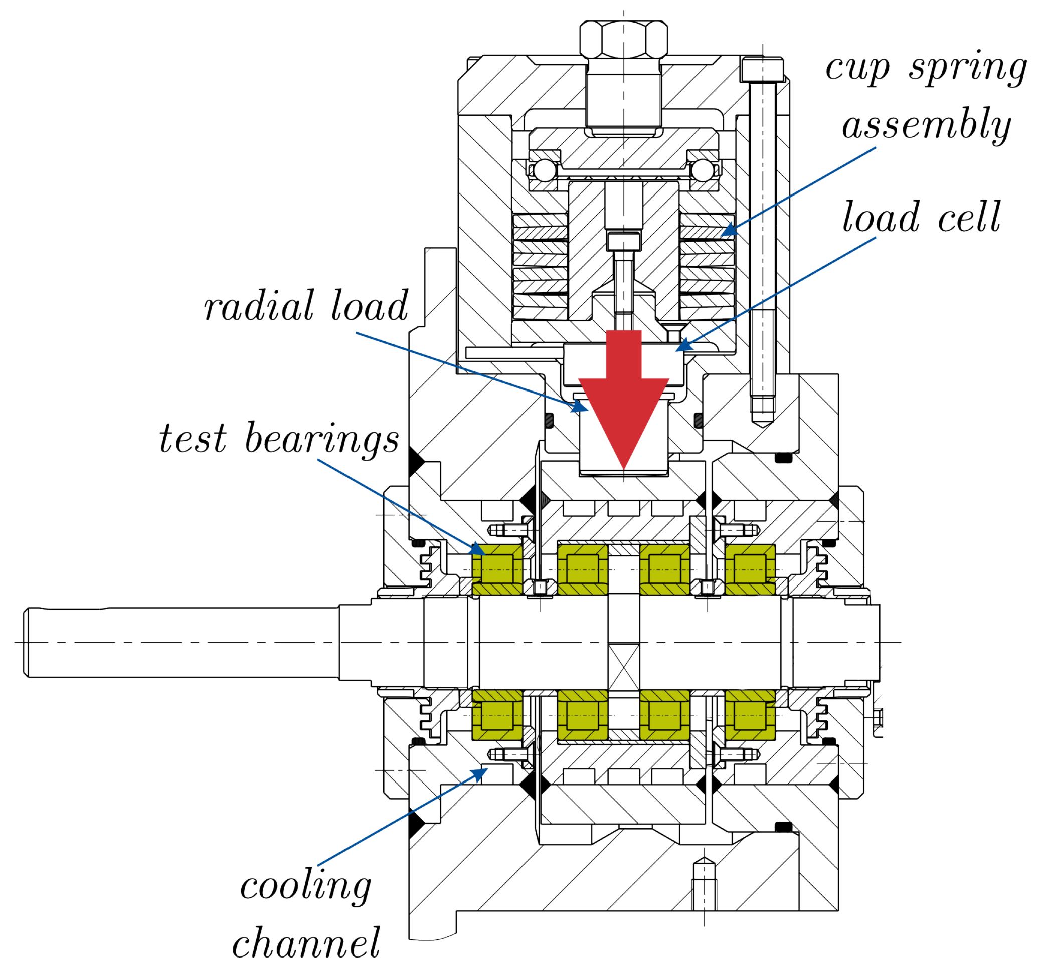
For the service life tests, a four-bearing radial fatigue life test rig, as seen in
Figure 6, was employed to determine the service life of radial bearings under electrical pre-stress conditions. Bearing failures were detected through vibration-based condition monitoring [
21]. This rig could apply radial loads up to
per bearing, corresponding to a C/P-value of 2.5 for NU206 cylindrical roller bearings, and accommodated various lubrication types and controlled temperature conditions.
Before and after each step of the investigations the bearings were thoroughly cleaned in an ultrasonic bath using both polar (isopropanol) and non-polar (benzine) solvents, followed by drying in an oven. After the service life tests the bearings were examined under a Keyence laser scanning microscope (Keyence VK-X200, Keyence, Osaka, Japan) and a reflective light microsocope (Keyence VHX 600, Keyence, Osaka, Japan). In particular, it was used to investigate the area surface roughness of the tested bearings.
2.2. Influence of Loaded Zone on Bearing Current
To prepare for the service life tests, the influence of radial load on the electrical pre-stress of the bearings was investigated. The mechanical load affects the size of the loaded zone and the number of rolling elements forming a high capacitive Hertz’ian contact. To understand how load distribution influences electric discharge phenomena, both theoretical and experimental studies were conducted.
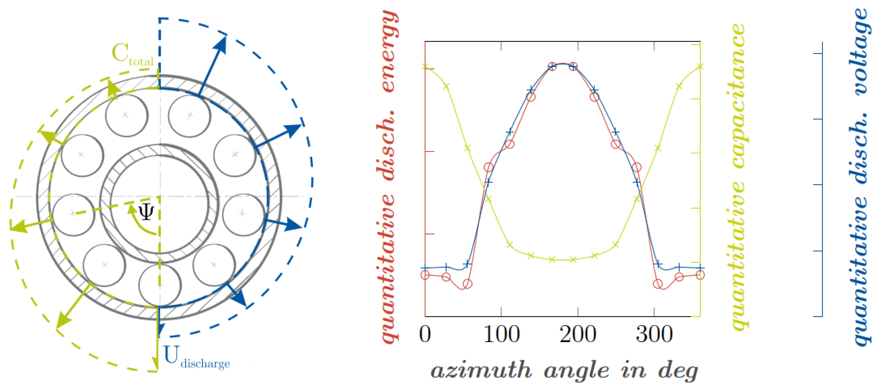
The correlation between the azimuth angle of the radially loaded bearing and its theoretical local capacitances, discharge voltages, and discharge energies is graphically illustrated in
Figure 7. Within the loaded zone, the capacitance
C is increased due to the reduced thickness of the contact’s lubricating film
. Essentially, the capacitance is a function of the electrical permittivity of the lubricant
and the ratio of the Hertz’ian contact area
and film thickness
. Extended methods to calculate this capacitance can be found in a number of works, e.g., [
12,
20,
22]. As is apparent from Equation (
1), the lower minimum film thickness
inside the loaded zone compared to the non-loaded zone also results in a lower discharge voltage
, since the insulating property of the lubricant, the dielectric strength, is exceeded more easily by the applied field strength
than in regions with higher film thicknesses. The energy
W stored in a capacitor then occurs as a result of its capacitance and the applied voltage. Since the energy at the time of discharge
is of interest, the critical discharge voltage must be inserted for the voltage term, and therefore Equation (
2) is obtained. It should be noted that if the film thickness decreases, the capacitance will rise and the critical breakdown voltage will decrease. However, it should also be kept in mind that the breakdown voltage in Equation (
2) is squared and therefore has a more significant influence on the total energy than the capacitance. This results in the red curve shown in
Figure 7.
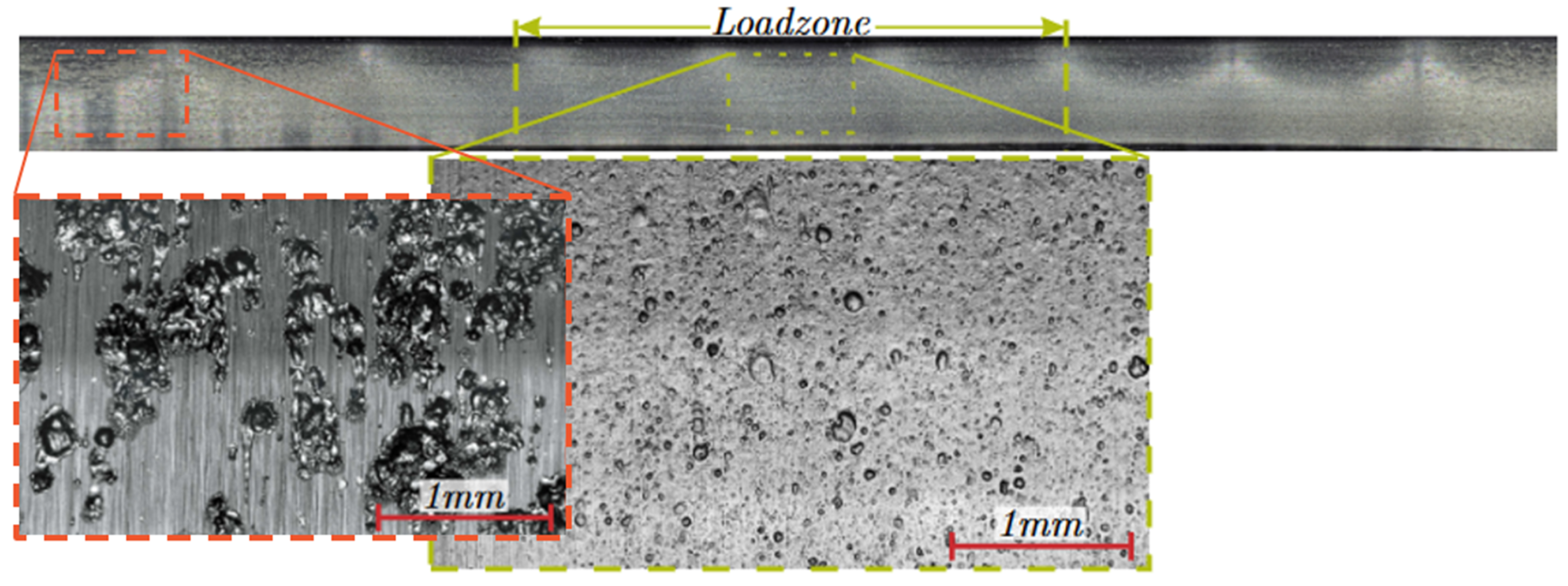
In summary, the likelihood of electric discharges is higher in the loaded zone, but each discharge releases a relatively low amount of energy compared to those outside the loaded zone, leading to different surface mutation characteristics. To test this hypothesis, an experiment was conducted with a hybrid NU206 cylindrical roller bearing equipped with a single steel rolling element under a radial load. After running in and applying electrical stress, the non-rotating outer ring was examined under a microscope. As expected, the loaded zone showed a “grey frosted” surface with numerous small craters, while the non-loaded zone exhibited fewer but larger craters, indicating a higher amount of discharge energy.
In summary, the likelihood of electric discharges is higher in the loaded zone, but each discharge releases a relatively low amount of energy compared to those outside the loaded zone, leading to different surface mutation characteristics. To test this hypothesis, an experiment was conducted with a hybrid NU206 cylindrical roller bearing equipped with a single steel rolling element under radial load. After running in and applying electrical stress, the non-rotating outer ring was examined under a microscope. The result is shown in
Figure 8. As the theoretical preliminary considerations suggested, inside the loaded zone, a grey frosted surface with numerous craters and regions affected by over-rolling can be observed. Opposite the loaded zone are fewer but larger craters, while relative large areas of the surface remain unaltered, which indicates a higher discharge energy than that inside the loaded zone. The rotating inner ring and the steel rolling element are subject to the full bandwidth of the electrical load, which is distributed over the entire outer ring, and exhibit a damage pattern regardless of the azimuth angle.
2.3. Experimental Service Life Investigations
To explore a range of electrical pre-stresses, the number of steel rolling elements in the modified hybrid bearings, as well as the value and duration of the discharge current from the current/voltage source, were adjusted to achieve the discharge energies listed in
Table 1. These adjustments were monitored using the described measurement equipment. In the first test series, efforts were made to exceed the limits defined by
Tischmacher and
Mütze [
13,
17]. The initial two experimental series used a laboratory voltage source, while subsequent series 3 and 4 employed an EDM source, leading to the ranges of electrical load shown in
Table 1.
During pre-stressing, the test bearings were equipped with at least two steel rolling elements, while the rest of the bearing was filled with ceramic rolling elements to accelerate the electrical pre-stress process. This setup prevented electrical discharges in the load-free zone, as excessive electrical surface mutation would result in damage that no longer corresponded to grey frosting. After the pre-stressing, the modified hybrid bearing was disassembled, cleaned, and equipped with non-stressed steel rolling elements except for one pre-stressed steel rolling element, ensuring we also took the influence of current-damaged rolling elements into consideration with regard to the service life investigations. The pre-stressed bearings of the different experiment series were then tested until failure in the four-bearing radial fatigue test rig. Failure detection was carried out via vibration sensors, and any failed bearings were replaced with new, non-pre-stressed bearings to continue the test cycle for the remaining pre-stressed bearings. The consistency of the test parameters was maintained across all experiment series and the parameters themselves are listed in
Table 2. The only difference between the test series is the electrical pre-stress induced on the universal test rig.
The listed
-value of 3 used in the tests was calculated for normal bearings that are not electrically stressed. It was observed that the pre-stressed bearings showed higher vibration and noise levels compared to non-stressed reference bearings. Despite anticipated full lubrication conditions for the used value of
, consistent lubrication was not always achieved, especially in the test series involving high discharge energies. This was verified through capacitive lubricating film measurements during operation [
10,
20].
3. Results of Experimental Service Life Investigations
While analyzing the failed bearing surfaces, it was apparent that the failure patterns showed a similar appearance throughout the majority of the tests. An example of such damage is shown in
Figure 9. It was recorded using a reflective light microscope and a laser-scanning microscope. The damage consistently featured a shallow spalling region with a depth of approx. 40
and a wave-like structure, which seemed to propagate opposite to the rolling direction. As shown in the rolling direction, some of these wave-like structures also had a deep spalling behind them.
One potential explanation for this wave-like structure lies in the melting and resolidification processes induced by electrical discharges. Tensile residual stress could have been introduced into the material to a depth of 0–40
[
23]. In addition, the material hardness below the hard and brittle surface was potentially reduced through the heat input of the discharges [
24]. This could facilitate subsurface crack formation, which is more likely to occur due to the softened steel beneath the surface, resulting in a core crushing mechanism [
25].
The service life test results are illustrated in Weibull diagrams, with each test series described briefly below.
3.1. Service Life of Test Series 1
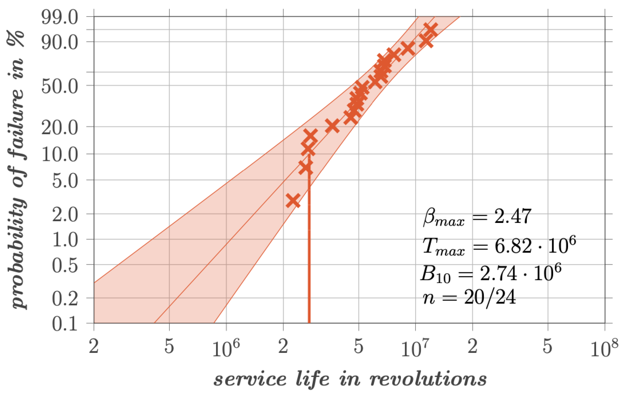
Test series 1 had the highest applied electrical stress among all test series. It is worth noting that no full-film lubrication could be detected capacitively during operation in this series. This can be attributed to the heavily roughened surface, which led to continuous contact between rough surfaces, preventing the development of a measurable capacitive charging curve. All observed surface spallings were found on the inner ring, similar to the one shown in
Figure 9. The Weibull distribution of all counted experiments from test series 1 is shown in
Figure 10. A total of 24 pre-stressed bearings were tested, with 20 categorized as failed items and the remaining four considered to be survivors. The experimental life of
revolutions and Weibull slope of
were obtained.
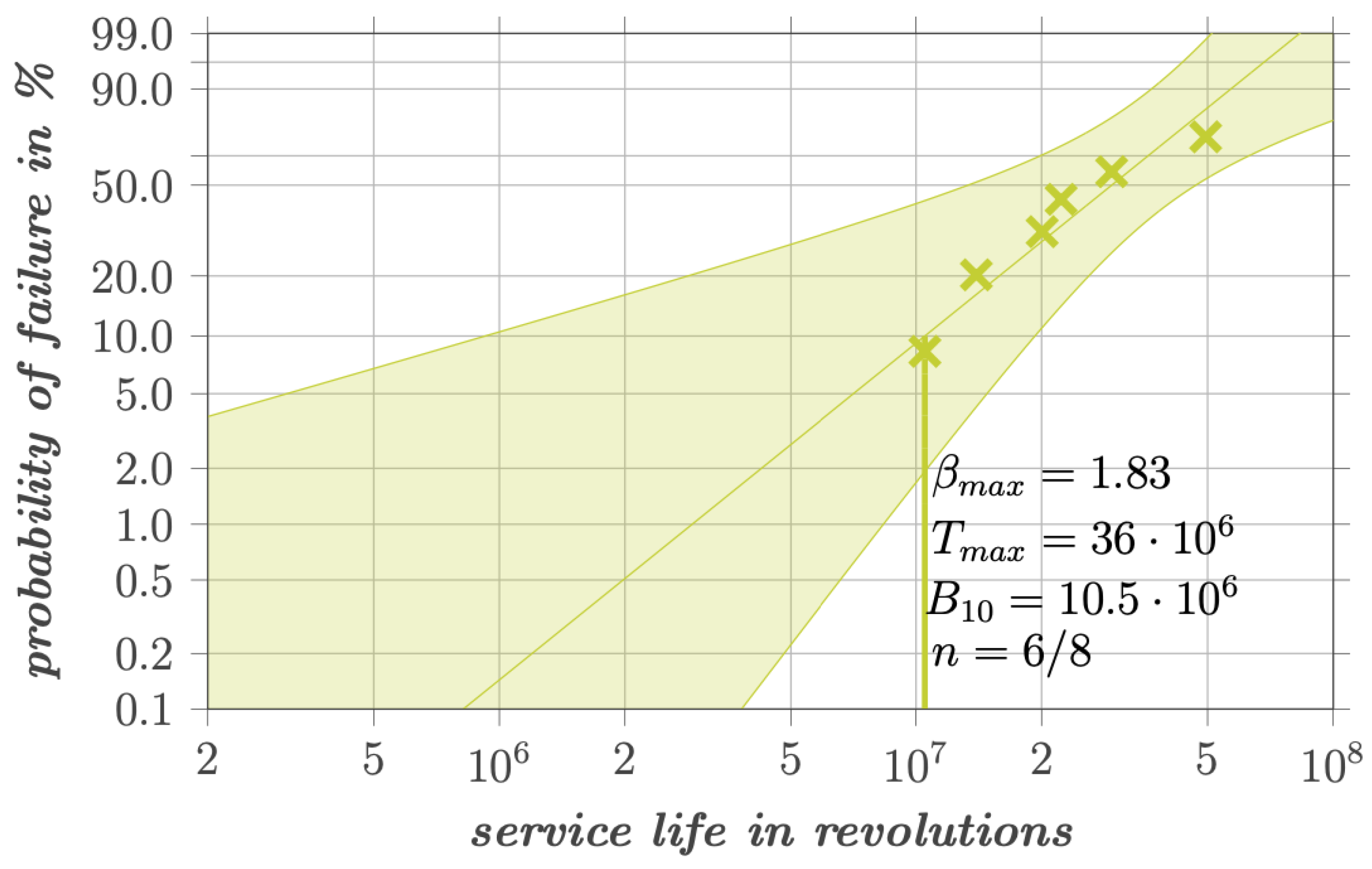
3.2. Service Life of Test Series 2
In test series 2, the electrical stress was significantly reduced. A total of eight bearings were tested, of which six failed, and two were rated as survivors. The experimental life of
revolutions and Weibull slope of
were obtained and shown in
Figure 11.
3.3. Service Life of Test Series 3
The electrical stress in test series 3 was even further reduced compared to series 1 and 2. An experimental life of
revolutions and Weibull slope of
for eight tested bearings were obtained and shown in
Figure 12.
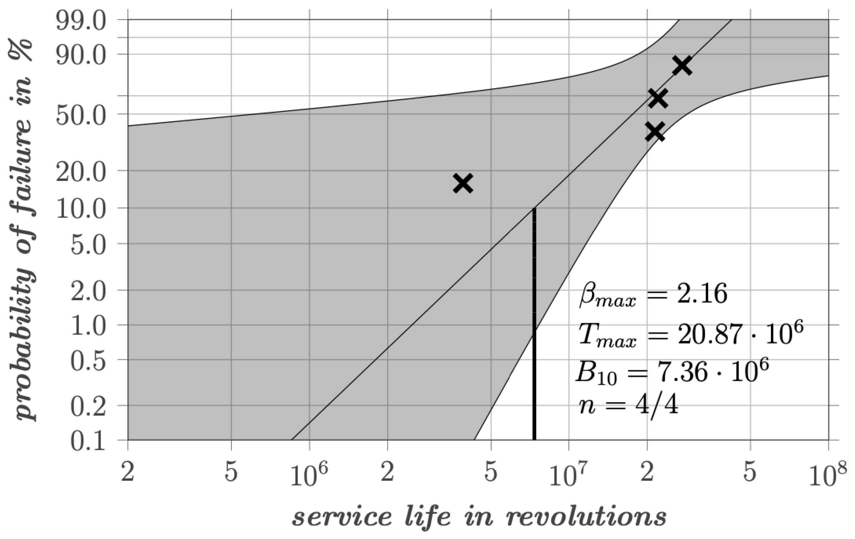
3.4. Service Life of Test Series 4
In the last test series the electrical stress was higher than in series 2 and 3 but lower than in series 1 (
Table 1). A total of four bearings were tested in this series, resulting in a large standard deviation. The obtained experimental service life is
revolutions with a Weibull slope of
and shown in
Figure 13.
3.5. Discussion of All Test Series
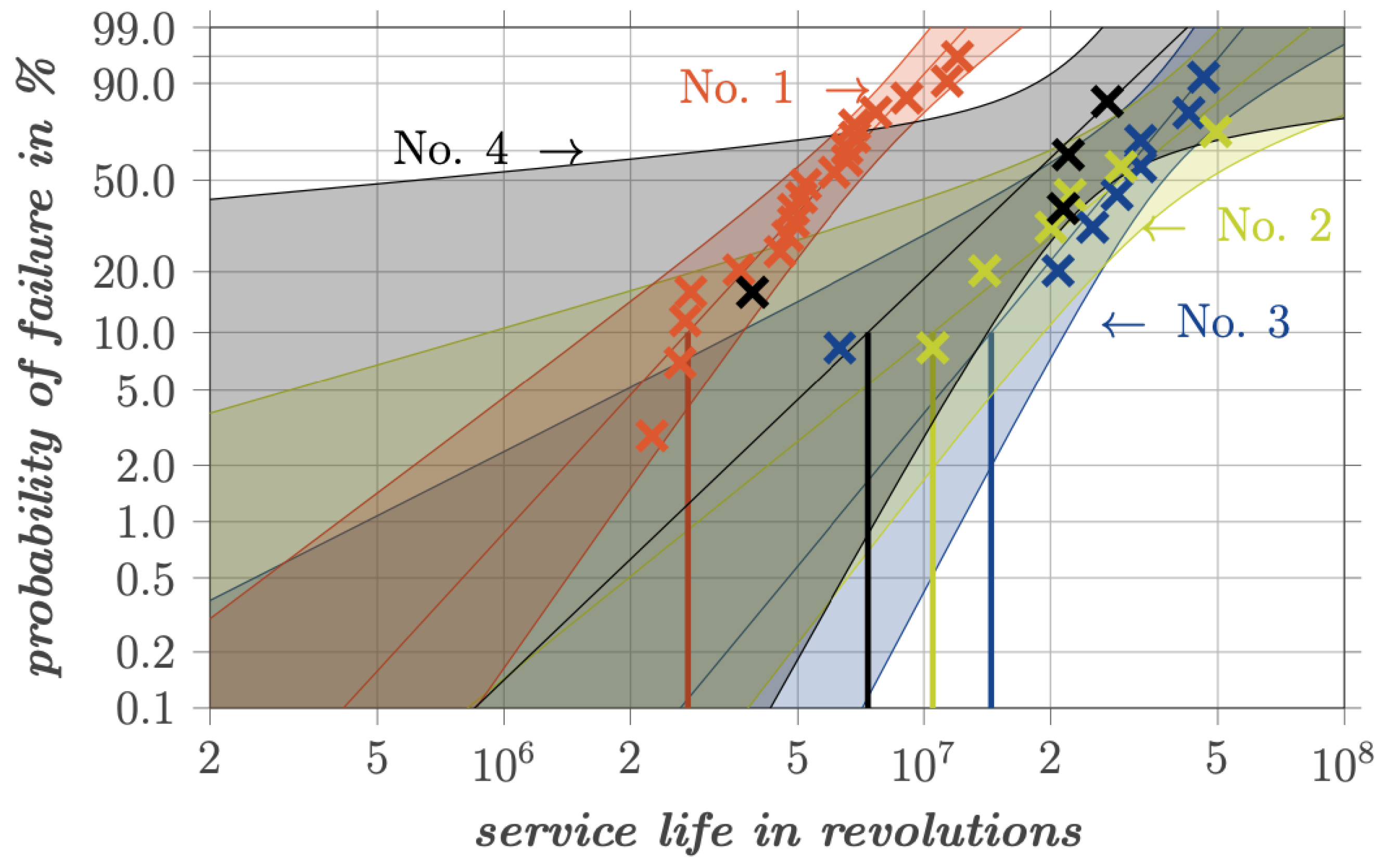
The experiments comprise the service life investigation of a total of 44 electrically pre-stressed cylindrical roller bearings. The overall results are summarized in a Weibull Graph in
Figure 14. The test series with higher electrical loads and therefore more severe pre-stress in form of grey frosting showed a shorter service life. This indicates that the failure of electrically stressed rolling bearings can be attributed to mechanisms other than fatigue and that current passage can indeed exert an influence on the service life that scale with the severity of the discharge energy. In comparison, reference tests from
Kehl [
26] obtained a service life of
revolutions and Weibull slope of
. He used the same test rig with the same mechanical loads, but with a viscosity ratio of
instead of 3. However, it should be pointed out again that this
value refers to reference (non-electrically stressed) bearings. The importance of this is discussed in the following section.
4. Extended Service Life Model
As shown in the previous section, it is apparent that electrical stress has an impact on the service life of rolling bearings. Consequently, the question arises: How can this influence be quantified and subsequently integrated into the calculation of rolling bearing service life? The conducted test series lead to the assumption that in the context of electrically stressed bearings, the surface roughness is an essential factor in the reduction of service life.
An internationally accepted method to calculate the service life is described in DIN ISO 281 [
27]. The equation for calculating the fatigue life of cylindrical roller bearings is based on the slice method, where the load distribution along one rolling element for
slices is used to calculate the modified rating life
.
The service life calculation is based on various parameters, such as the viscosity ratio
, the contamination coefficient
, the fatigue load limit
, dynamic equivalent load
, and the dynamic load rating
, as well as the dynamic load rating
of each
k-th slice. Unfortunately, the influencing factors in the equation do not include the influence of the surface roughness. To include surface roughness, the viscosity ratio
(Equation (
4)) must be modified. This ratio characterizes the relationship between operational
and nominal kinematic viscosity
, thereby reflecting the lubrication condition in the fatigue life equation. Under normal circumstances, it is assumed that the surface roughness corresponds to that of non-electrically stressed bearings.
To link the viscosity ratio
with surface roughness, the parameter
is introduced [
28,
29]. It includes the elastic deformation of micro-roughness peaks, minimum
and central film thickness
and the area-related roughness value of the reduced peak height
. Bearings that were electrically stressed and run-in not-stressed reference bearings were measured with a laser scanning microscope to initially calculate the
value. The measured values from each test series and the reference to be able to apply the method from
Hansen to calculate
are listed in
Table 3.
With the result of the reference bearing, it is possible to establish a relationship between
and
, since the
value would always refer to a normal surface finish. As shown in
Figure 15a, an approximation line can be effectively fitted. Based on the results, it is assumed that the correlation between both values is linear and can be described by the following equation:
Using the measured roughness values from the electrically mutated surfaces, it is possible to determine the
-value and to use Equation (
5) to determine the corresponding
value, as shown in
Figure 15b. This can then be used as an input for Equation (
3).
To summarize the outlined procedure, the four steps that must be performed sequentially are briefly listed as follows:
- 1.
Measurement of surface roughness.
- 2.
Calculation of .
- 3.
Calculation of .
- 4.
Determine theoretical service life with method from DIN ISO 281.
Using the new viscosity ratios, it is now possible to correlate the experimentally determined service life of the electrically stressed and reference bearings from [
26] with the calculated service life from Equation (
3). The values with the associated experimental service life are listed in
Table 4.
The service life plotted against the viscosity ratio is shown in
Figure 16. It can be seen that the
-values of the electrically pre-stressed bearings differed substantially between the test series, even though a viscosity ratio for non-stressed bearings of
was set. In particular, for experiment series 1 and 4, which were characterized by higher electrical loads, the
-value was significantly lower than those for series 2 and 3, indicating mixed lubrication. This was also confirmed via capacitive measurements during the experiments. It is also apparent that the level of electrical stress directly translated to the degree of surface roughness. The higher the electrical stress, the higher the surface roughness. The newly categorized service lives of the pre-stressed bearings matched the calculated service life quite well. However, a considerable reduction in service life was observed in the area of full lubrication compared to the reference tests. Even test series 3, which had the lowest electrical load, achieved a comparably shorter service life with
rev. than the reference test with similar lubrication conditions of
rev. In the regime of mixed lubrication, the lubrication regime exerts a predominant influence on the bearing’s performance. Under these conditions, the differences in service life between electrically pre-stressed bearings from test series 4 and reference bearings are minimal.
5. Conclusions and Outlook
The experimental investigations presented in this study provide insights into the impact of electrical pre-stressing on the service life of rolling bearings. The results indicate that electrical discharges, which manifest in the form of EDM currents and circular bearing currents, can lead to notable surface mutations and reduce the service life of the bearings. The induced surface damage, characterized by grey frosting, craters, and in severe cases, fluting, results in increased vibration and noise levels, ultimately affecting the operational integrity and longevity of the bearings.
The experimental data derived from controlled electrical pre-stressing and subsequent service life tests reveal a clear correlation between the severity of electrical pre-stress and the reduction in bearing life. The Weibull analyses of the different test series demonstrate that higher discharge energies correlate with shorter bearing service lives. For instance, test series 1, which had the highest electrical load, exhibited a significantly reduced service life ( revolutions) compared to the less electrically stressed bearings in the test series 3 ( revolutions).
The surface damages observed in the bearings after the service life test was stopped included shallow spalling with wave-like structures, which is indicative of the melting and resolidification processes induced by electric discharges. These structural changes may introduce tensile residual stress and reduce material hardness, contributing to the reduced fatigue life. The study also highlights the importance of considering the influence of surface roughness and lubrication conditions when evaluating the service life of electrically stressed bearings, as it seems to be the main reason for a shortened service life.
An extended service life model was proposed in this study, which incorporates the effect of electrical surface mutations by modifying the viscosity ratio . This modification accounts for the altered lubrication conditions due to increased surface roughness, providing a more accurate prediction of the bearing’s service life under electrical stress. Using this test methodology, it can be concluded that the service life under mixed friction conditions exhibits minimal deviation from the reference tests. However, significant differences are observed under full lubrication, suggesting that the failure mechanisms in electrically pre-stressed bearings diverge from traditional fatigue mechanisms.
In conclusion, the findings underscore the necessity for further research into the mechanisms of electric discharge-induced damage in rolling bearings and the development of advanced models for service life prediction.
