1. Introduction
Total hip arthroplasty (THA) surgery is a globally performed procedure that involves the removal of a damaged or diseased hip joint, replaced by a prosthetic implant fixed in the bone to restore anatomy and mobility [
1]. Despite its success, the statistical survival of prosthetic hip implants decreases over time, resulting in complicated revision surgeries that can give rise to economic and health challenges [
2]. Studies reveal that the typical lifespan of implants ranges from 15 to 25 years, a duration considered unacceptable especially for young patients [
3]. Common causes of prosthetic hip implant failures, such as osteolysis, loosening, and mechanical complications [
4], are often linked to wear debris from the implant’s bearing surfaces [
5]. Consequently, addressing the challenge of reducing wear on these bearing surfaces remains a crucial focus of ongoing research.
Minimizing the friction and wear in prosthetic hip implants encompasses both material enhancement and surface engineering approaches. Improving the materials and mechanical properties involves optimizing the selection, manufacturing, and characteristics of materials to enhance durability. Specifically, vitamin E-infused and highly cross-linked ultra-high molecular weight polyethylene (UHMWPE) exhibits lower wear rates than traditional UHMWPE material, due to the increased strength and toughness caused by the cross-linking [
6], and the enhanced fatigue resistance caused by the antioxidant vitamin E [
7]. Improved ceramics manufacturing has reduced the incidence of fracture in the ceramic bearing surfaces of prosthetic hip implants from as high as 13% in some reports to less than 0.004% [
8].
Surface engineering methods include tribology-inspired solutions such as coating the bearing surfaces with hard and smooth material such as diamond-like carbon intended to improve wear resistance [
9]. Nevertheless, the issue of delamination poses a constraint on its utilization [
10]. A patterned surface texture has proven effective in reducing friction and wear by incorporating various mechanisms [
3,
11]. Large and deep texture features serve as wear particle traps, thereby minimizing abrasive interactions and promoting a stable friction coefficient [
12,
13], and function as lubricant reservoirs, facilitating a consistent and readily available lubrication supply during sliding [
14,
15]. The textured surface contributes to a reduction in the nominal contact area, diminishing direct surface contact and friction [
16]. Furthermore, shallow texture features aid in increasing hydrodynamic pressure, promoting a load-carrying lubricating film between the contacting surfaces [
17].
Numerous studies show that textured surfaces reduce friction and wear between prosthetic hip implant bearing surfaces. Ito et al. experimentally showed that large texture features (500 μm diameter, 100 μm depth) on a cobalt–chromium femoral head produced 36% less wear in a UHMWPE counter face than a smooth femoral head because of the lubricant reservoirs and trapped wear debris [
18]. Tarabolsi et al. demonstrated large accumulation of wear debris in texture features on cobalt–chromium- and ceramic-bearing surfaces and measured a significant decrease in the total wear volume compared to smooth bearing surfaces [
12]. Dong et al. experimentally measured that shallow texture features (<10 μm deep) increased the lubricant film thickness compared to smooth bearing surfaces [
19]. Borjali et al. showed that shallow texture features on cobalt–chromium discs reduced the friction coefficient and wear rate of UHMWPE pins by inducing the hydrodynamic lubrication regime under conditions that caused boundary/mixed regime in smooth bearing surfaces [
20]. Allen and Raeymaekers used elastohydrodynamic lubrication simulations to model how the lubricant film thickness changes with texture design parameters and bearing operating conditions, indicating that optimal texture designs can be determined for individual operating conditions [
21,
22].
Multiscale texture features commonly occur on natural surfaces and can provide enhanced tribological performance by combining various functions on the same surface. For instance, the microstructures on a lotus leaf make the surface hydrophobic and allow for self-cleaning [
23]. On shark skin, textured scales reduce drag [
24] and hierarchical structures on gecko feet facilitate extraordinary adhesive force [
25]. Articular cartilage surfaces naturally possess “dimple” surface texture features with diameters ranging from 20 to 50 μm and depths of 0.5 to 2 μm. These dimple texture features play a crucial role in enhancing lubrication for the joint bearing surface [
26]. Thus, multiscale textures exist to optimize surface physical properties, allowing adaptation to a variety of natural environments. Furthermore, these textures have the potential to reduce friction and enhance wear resistance [
27,
28], thereby increasing the efficiency and longevity of tribo-pairs.
The influence of multiscale textures in diverse tribological applications has been studied by several research groups. Segu et al. examined the effect of multiscale/shape texture features on lubricant regimes using laser-textured round and ellipse dimples on a steel surface and showed a consistently low friction coefficient attributed to hydrodynamic lubrication effects [
29]. Resendiz et al. demonstrated that multiscale texturing on Al6061-T6 surfaces by inclined milling and micro shot blasting process reduced friction and wear compared to untextured and single-scale textured surfaces, attributed to increased lubricant fluid pressure [
30]. Zhang et al. studied hierarchical structures created by an ion beam etching of a laser-textured Co–Cr–Mo alloy surface and observed friction and wear performance improvement, attributed to a decreased contact area, stored lubricant, and increased lubricant film thickness [
31]. Hsu et al. investigated how sliding orientation and specific texture parameters are crucial for achieving effective friction reduction in each lubrication regime [
32]. In a subsequent experimental investigation, the same research group compared single-scale, mixture (alternating between two shapes), and overlapped (placing one texture feature on top of another) multiscale texture designs under a wide range of loads and speeds. The results indicated that multiscale surface textures reduce friction more effectively across various lubrication regimes compared to single-scale dimples [
33].
Therefore, multiscale textures on bearing surfaces offer a distinct advantage over single-scale textures, particularly in dynamic loading and varying speed conditions like those experienced by prosthetic hip implants. Multiscale textures can enhance performance by accommodating varying speeds and forces, improving lubrication, reducing wear, and extending the lifespan of prosthetic hip implants through shortening the time working under the boundary and/or mixed lubrication regime during the gait cycle.
Previous studies have primarily focused on single-scale textures to enhance tribological properties. However, this paper aims to determine the influence of multiscale textures on lubricant film thickness in the context of prosthetic hip implant applications. Various multiscale texture design parameters were investigated within reasonable bearing operating conditions to identify the optimum surface parameters. The objective is to develop a bio-inspired solution to decrease the friction coefficient and wear of prosthetic hip implants by increasing the lubricant film thickness between articulating surfaces.
2. Materials and Methods
2.1. Optimization of Multiscale Texture Design Parameters
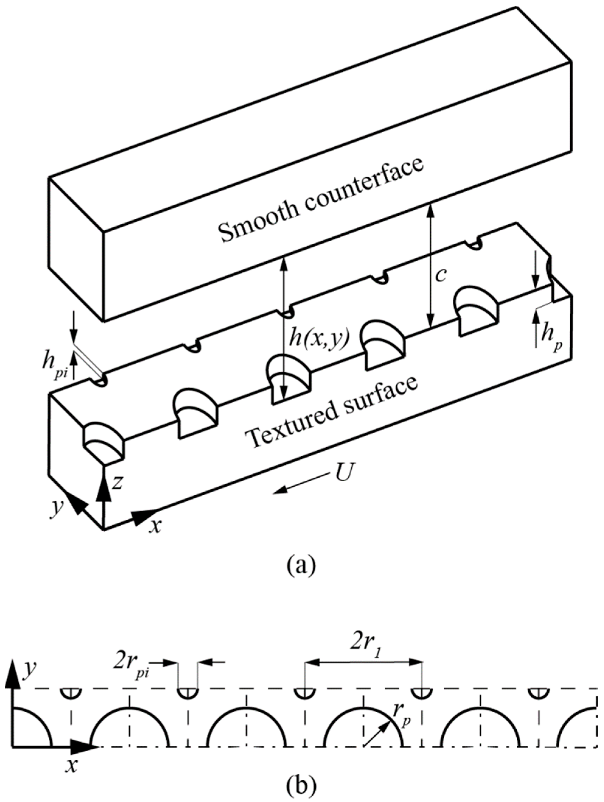
We developed a hydrodynamic lubrication (HL) model of a bearing surface with a repeating pattern of multiscale texture features in lubricated sliding parallel with a flat counter face as shown in
Figure 1. The multiscale texture pattern occurs as a combination of the microscale texture features, with smaller “interstitial” texture features in between, and the pattern repeats in the
x- and
y-directions. The cylindrical shaped texture features (flat texture floor shape) are fully described by the non-dimensional parameters of texture density,
Sp = πrp2/4
r12, and texture aspect ratio,
ε =
hp/2
rp, where
rp is the texture feature radius,
hp is the depth of the texture feature, and
r1 is the half-length of a unit square that surrounds each texture feature. The smaller, interstitial texture features are similarly defined with texture density and aspect ratio, i.e.,
Spi = πrpi2/4
r12 and
εi =
hpi/2
rpi, where
rpi is the radius and
hpi is the depth of the interstitial texture features.
We solve the Reynolds equation for the lubricant film pressure using finite differencing. The two-dimensional, steady-state, isothermal, and iso-viscous Reynolds equation is given in Equation (1),
where
x and
y are Cartesian coordinates,
h and
p are the thickness and pressure of the lubricant film, respectively,
μ is the lubricant dynamic viscosity, and
U is the relative surface velocity in the
x-direction. We introduce non-dimensional parameters so the simulation results can be applied to any bearing system, independent of texture dimensions and lubricant properties. Specifically,
X =
x/
rp,
Y =
y/
rp,
H =
h/
c, and
P =
p/
p0, where
p0 is atmospheric pressure (101,325 Pa) and
c is the separation between bearing surfaces. Furthermore, the parameter
λ = 3
μU/2
rpp0 is known as the flow factor, as it incorporates the lubricant viscosity and the relative bearing surface velocity. The parameter
δ =
c/2
rp is the non-dimensional bearing spacing. The Reynolds equation expressed with non-dimensional parameters is given in Equation (2).
The simulation domain consists of half of an array of 5 texture features with symmetry boundary conditions on the centerline and the edge of the array to reduce the computation time. The inlet and outlet of the texture feature array are kept at atmospheric pressure.
We employ an Elrod algorithm to enforce mass-conserving Jakobson–Floberg–Olsson (JFO) cavitation boundary conditions. Specifically, we include a fractional film content parameter,
θ, in the non-dimensional Reynolds equation.
Thus, each point in the solution domain can revert between the cavitation and full-film regimes. In the cavitation regime, the pressure remains at the cavitation threshold (chosen as the vapor pressure of water at 5630 Pa for a worst-case conservative estimate). The center of a texture feature is positioned at the bearing inlet, as the JFO cavitation condition does not produce positive lubricant film pressure if the bearing inlet is untextured [
34,
35]. We discretize the solution domain with a matrix of nodes, equally spaced in the
x- and
y-directions. We set an initial non-dimensional bearing spacing,
δ0, and iterate on solutions of Equation (3) until successive iterations of the lubricant film pressure are different by less than a critical convergence criterion. Convergence studies show that
n = 201 nodes across the length of a unit cell (2
r1) and a convergence criterion of 0.0001 are sufficient to achieve accurate simulation results of the lubricant film pressure. We compare the simulated lubricant film pressure to the desired bearing load and change the value of
δ until the converged solution carries the applied load.
We test different multiscale texture design parameters to identify the most advantageous combination for maximizing the lubricant film thickness.
Table 1 shows the maximum and minimum values of the texture design parameters and bearing operating conditions considered in these simulations, as well as the nominal values that were held constant when varying other parameters.
2.2. Sample Preparation and Laser Surface Texturing
We conducted an experimental procedure with the aim of validating the simulation outcomes, emphasizing the achievement of maximum lubricant film thickness. The critical texture parameter selection criterion depends on feasible minimum depth of the smallest texture feature, which is set at 0.73 µm for effective direct laser texturing. Depths below this threshold posed a risk of introducing roughness and waviness to the texture feature bottom surface, potentially exceeding the top flat surface. We selected three samples for multiscale textures with the same microscale texture features and the same interstitial texture aspect ratio but varying in interstitial texture density. Additionally, we selected two samples for comparison with just microscale texturing and an untextured surface.
The widely used biomaterial, CoCrMo, releases harmful metal ions, resulting in tissue reactions and a decreased lifespan. Thus, Ti6Al4V implants with enhanced surface engineering are being studied as an alternative due to their biocompatibility and strength. Biomedical-grade Ti6Al4V alloy discs (grade 5), with a diameter of 30 mm and a thickness of 6 mm, were polished to achieve a mirror finish surface roughness Ra below 50 nm. The surface roughness was measured with laser scanning confocal microscope (KEYENCE VK-100, Keyence Co., Osaka, Japan). The polished samples were then subjected to 15 min of ultrasonic cleaning with acetone. To ensure complete drying and prevent the introduction of moisture-related issues or contaminants, the heat drying process followed at 70 °C for 30 min. For the friction test, the Ti6Al4V disc was paired with flat biomedical-grade UHMWPE (GUR 1020) pin with a diameter of 4 mm and a length of 10 mm. The molecular weight of the UHMWPE is around 5.5 million g/mol. The material characteristics of UHMWPE and Ti6Al4V are provided in
Table 2.
The design for just microscale texture features was adapted from a prior numerical study [
22], aiming for maximum film thickness, comprising an aspect ratio of 0.022 and a texture area density of 0.2. Interstitial textures, designed with a constant aspect ratio of 0.025 and a varying texture area density ranging from 0.0176 to 0.0706, were selected for the manufacturing process.
Table 3 presents geometrical parameters of the texture features on Ti6Al4V surface.
Laser surface texturing was carried out using a commercially available picosecond laser system, (diode-pumped solid-state laser, Advanced Optowave, Ronkonkoma, NY, USA). The system generates
τL = 10 ps laser pulse at wavelength λ = 1064 nm and we employed pulse energy
Ep = 250 μJ at a repetition rate of
fp = 100 kHz to produce the microtextures. The picosecond laser produces pulses of linearly polarized light with the Gaussian intensity distribution. The diameter of laser spot was 14.4 µm at the focal point on the sample surface. A spiral laser path approach was used to remove material inside the circular shape micro textures [
36]. The fabrication of various dimple sizes was accomplished using a single-step process [
28], although various process repetitions were necessary to achieve the required dimple depths. Before surface characterization, the samples underwent a 30-min ultrasonic cleaning in acetone. A confocal microscope (Keyence VK-100, Keyence Co., Osaka, Japan) was used for surface characterization of the fabricated microtextures.
2.3. Contact Angle Measurement
The wettability of the sample surfaces was characterized by the contact angle (CA) measurement with water droplets (OCA25, Dataphysics Instruments GmbH, Filderstadt, Germany). This instrument is capable of measuring a contact angle with a resolution of 0.1°. Measurements were conducted at a room temperature of approximately 25 ± 1% °C and a relative humidity of around 50 ± 5%. Contact angle values were obtained through the direct observation, analysis, and calculation of the shape of liquid droplets (sessile drop) formed on horizontally placed solid surfaces. The deposition of drops was detected using an automatic recognition technique integrated within the interface measurement and analysis software of the system. The droplet size was regulated utilizing an electric injection device with a liquid addition and return rate (LAR) set at 0.5 µL/s. Initially, 4 µL of liquid was dispensed, followed by inserting the needle into the liquid for continuous addition of another 4 µL. The system remained stable for 100 s before retracting the 4 µL of liquid back into the needle. We conducted five repetitions of the contact angle (CA) test at different locations on each sample to ensure reproducibility and precision. The average values were then calculated and presented, with the maximum standard deviation observed being 3.1%, assuring that the recorded values in each area of the sample were similar, thus justifying their averaging.
Water was selected as the test fluid for contact angle (CA) measurements due to its versatility and validity. A study by Zhang et al. [
31] revealed similar wetting trends between water and bovine serum on textured surfaces. Notably, bovine serum consistently demonstrated lower contact angles than water, implying that using water could yield more conservative results.
The advancing contact angle is determined as the solid/liquid contact area expands, while the receding contact angle is measured as the contact area decreases on the surface. The difference between advancing and receding angle is known as contact angle hysteresis (CAH) in the liquid–solid interface. A large CAH (i.e., significant differences between advancing and receding contact angles) indicates strong surface interactions that enhance the wetting behavior.
2.4. Pin-on-Disc Friction and Wear Measurement
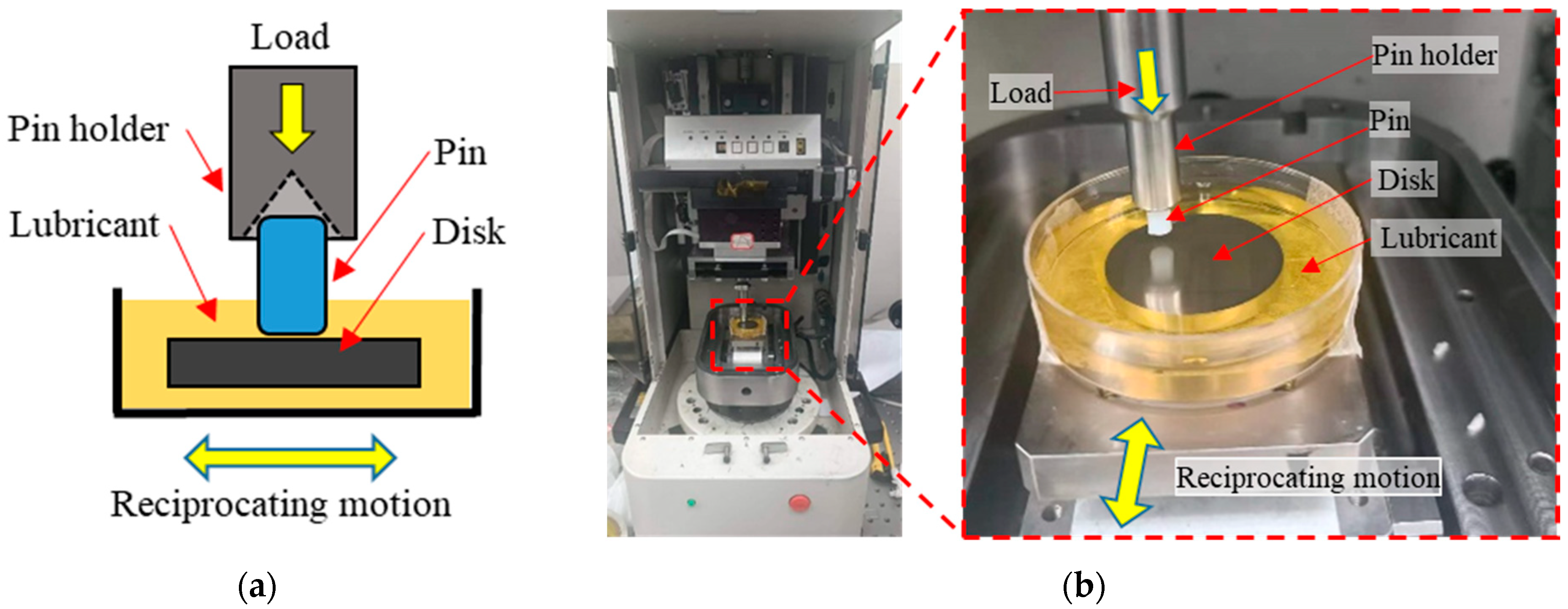
The friction and wear performance of just microscale textured, multiscale textured, and untextured surfaces were evaluated with a pin-on-disc setup by a reciprocating sliding test conducted on a UMT-2 tribometer under lubricated conditions.
Figure 2a illustrates the schematic diagram of the pin-on-disc setup, and
Figure 2b shows a photograph of the setup. The upper sample, featuring a cylindrical shape and a flat-ended UHMWPE pin, slides over Ti6Al4V discs. All tests were conducted at a constant frequency of 1 Hz, a sliding distance of 15 mm for 1000 cycles, and a load of 6.28 N, creating a contact pressure of 0.5 MPa. This contact pressure is within the expected range experienced by real hip implants, and the choice of these parameters was in accordance with the parameters used for the simulations.
Bovine serum containing a protein concentration of 15 mg/mL served as the lubricant. We maintained lubricating liquid viscosity by controlling temperature and minimizing contaminants. We ensured consistent lubrication conditions and prevented disintegration by uniformly applying the lubricant, inspecting for degradation, implementing quality control measures and maintaining a stable testing environment.
For the self-alignment of the flat pin surface with the flat disc surface, a conical-shaped pin holder was utilized to hold and apply pressure to the top side of the pin, as depicted in
Figure 2a. To ensure the repeatability of friction measurements, a minimum of three measurements were conducted for each sample, and the average values were subsequently reported.
3. Results
3.1. Typical HL Solution for Each Scale of Texture Features
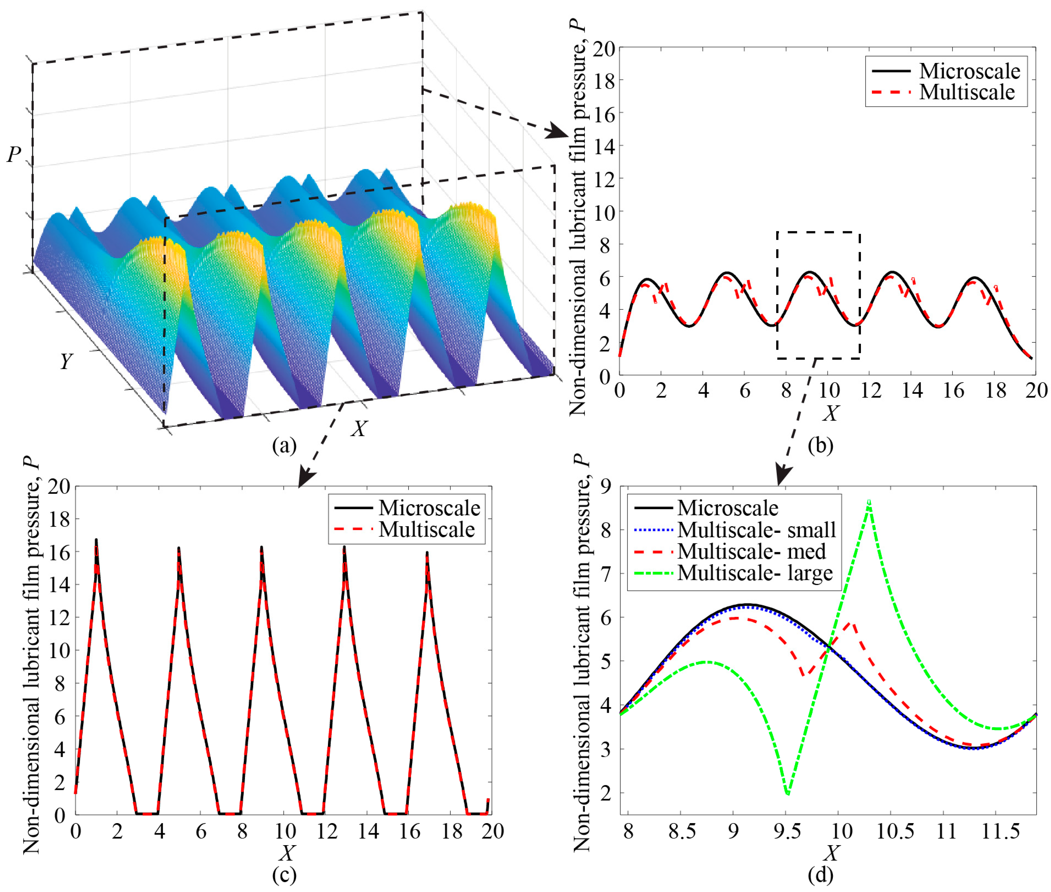
The simulation results include the lubricant film pressure as well as the lubricant film thickness at each point in the domain.
Figure 3a shows a typical three-dimensional result of the lubricant film pressure across the solution domain with
W = 4.935,
λ = 0.300,
Sp = 0.200,
ε = 0.050,
Spi = 0.010, and
εi = 0.020.
Figure 3b shows the contour of lubricant film pressure along the edge of the texture feature array for simulations with the combined multiscale texture features (black solid line) and for just the microscale texture features (red dashed line).
Figure 3c shows the contour of lubricant film pressure along the centerline of the microscale texture feature array. We see from
Figure 3c that the lubricant film begins at atmospheric pressure at the bearing inlet and increases to a maximum value at the outlet of the first texture feature because the texture outlet creates a converging flow. Each texture inlet causes a diverging flow that reduces the lubricant film pressure to the cavitation limit. The simulations with just microscale texture features and the combined multiscale texture simulations are virtually identical at this centerline.
The edge contour in
Figure 3b passes between microscale texture features and through the center of the interstitial texture features. From this figure, we observe that the solution with only microscale texture features shows a repeating increase and decrease in the lubricant film pressure, corresponding to the locations of the microscale texture features in the
X-direction. The combined multiscale texture solution shows an additional slight decrease followed by a slight increase in pressure due to the extra diverging and converging channels from the interstitial texture features.
Figure 3d shows a magnified view of the lubricant film pressure contour for the centermost texture features at the edge of the array for the microscale texture features (black solid line) and three different sizes of interstitial texture features in a multiscale array (blue, red, and green lines). Increasing the size of the interstitial texture features leads to a greater disruption of the lubricant film pressure in this region of the array, but the deviations are similar in both the positive and negative directions. The interstitial texture features do not cause cavitation at the conditions simulated here, and the net influence of the interstitial texture features on the lubricant film pressure is small compared to the microscale texture features. Both texturing conditions have the same load-carrying capacity,
W = 4.935, but the combined multiscale texture features resulted in a slightly thicker lubricant film (
δ = 0.0488) compared to the solely microscale texture features (
δ = 0.0484). This is due to the interstitial texture features increasing the volume of lubricant between the bearing surfaces and acting as additional micro-hydrodynamic bearings.
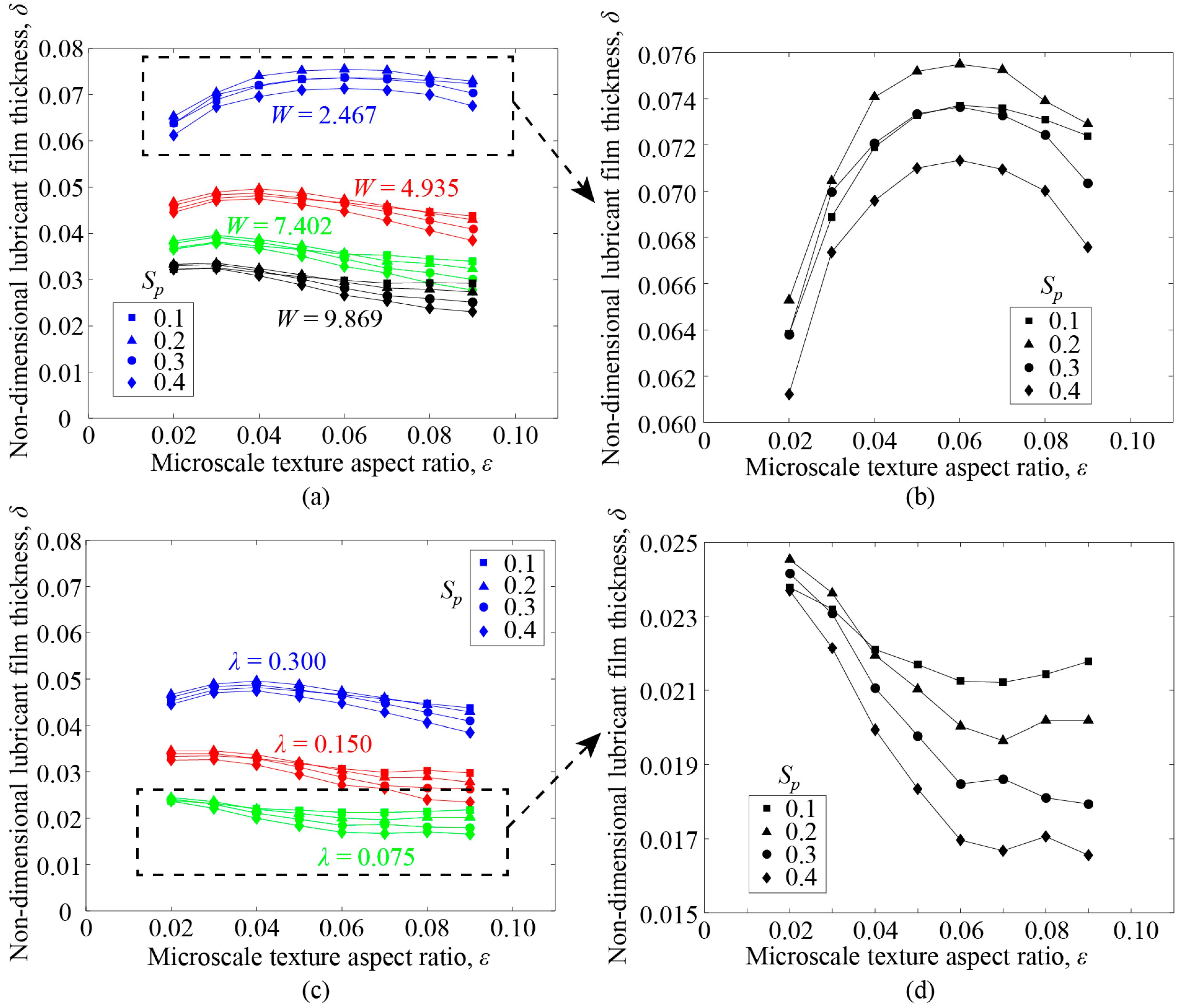
3.2. Effect of the Microscale Texture Features
To determine the effect of changing the microscale texture features on a multiscale textured surface, we perform simulations with varied texture feature design parameters (
Sp and
ε), keeping the interstitial texture features constant (
Spi = 0.01,
εi = 0.02). In each simulation, we calculate the non-dimensional lubricant film thickness (i.e., non-dimensional bearing spacing,
δ) required to generate sufficient lubricant film pressure to carry the applied load.
Figure 4 plots this film thickness as a function of the microscale texture aspect ratio.
Figure 4a shows different values of the load-carrying capacity,
W, in different colors and
Figure 4b shows a magnified view of the simulation results with
W = 2.467.
Figure 4c shows different values of the flow factor,
λ, in different colors and
Figure 4d shows a magnified view of the simulation results with
λ = 0.075. Increasing the load-carrying capacity and decreasing the flow factor reduce the lubricant film thickness because the bearing surfaces are compressed closer together, or because the lubricant viscosity or the bearing surface velocity has decreased, which reduces the hydrodynamic pressure generation. We also see that a texture density of
Sp = 0.2 results in the maximum lubricant film thickness for each simulated condition. There is an optimal texture aspect ratio that maximizes the lubricant film thickness, however, the value of the optimal texture aspect ratio changes with the bearing operating conditions. Specifically, the optimal texture aspect ratio increases with operating conditions that increase the lubricant film thickness (i.e., increasing
λ and decreasing
W), similar to the results reported in [
22].
3.3. Effect of the Interstitial Texture Features
To determine the effect of changing the interstitial texture features on a multiscale textured surface, we perform simulations with varied interstitial texture feature design parameters (
Spi and
εi), keeping the microscale texture features constant (
Sp = 0.02,
ε = 0.05).
Figure 5 shows the non-dimensional lubricant film thickness as a function of the interstitial texture aspect ratio.
Figure 5a includes results for
λ = 0.300 and different values of the load-carrying capacity (
W = 2.467 in blue,
W = 4.935 in red,
W = 7.402 in green, and
W = 9.869 in black), and
Figure 5b shows a zoomed-in view of the simulations with
W = 4.935. A dotted line shows the lubricant film thickness for a bearing surface with only microscale texture features under the same bearing operating conditions.
Figure 5c plots the non-dimensional lubricant film thickness as a function of the interstitial texture aspect ratio for different values of the flow factor (
λ = 0.300 in blue,
λ = 0.150 in red, and
λ = 0.075 in green).
Figure 5d shows a magnified view of the results with
λ = 0.075. Again, we observe that the lubricant film thickness decreases as the load-carrying capacity increases and as the flow factor decreases, because the increased loads push the bearing surfaces closer together and the lubricant viscosity or bearing surface velocity are decreased. At the conditions simulated here, the interstitial texture features have a slight effect on the overall lubricant film thickness. However, from the zoomed-in view in
Figure 5b, we see that the lubricant film thickness increases as the interstitial texture density and aspect ratio decrease. We also observe that the interstitial texture features increase the lubricant film thickness compared to the microtextured surface at these simulation conditions (
λ = 0.300 and
W = 4935).
In
Figure 5d, we see the same trend repeated, namely that the lubricant film thickness increases as the interstitial texture feature density and aspect ratio decrease. However, at these simulated conditions, the interstitial texture features resulted in a very slight decrease in lubricant film thickness compared to the microscale texture features, and the multiscale texture features approach the microscale solution as the interstitial texture aspect ratio decreases.
The interstitial texture features provide a slight increase in the lubricant film thickness compared to the microscale textures for the simulations with high load (W = 4.935, 7.402, and 9.869) and cause a slight decrease in lubricant film thickness compared to the microscale textures for a low load (W = 2.467) and small values of the flow factor (λ = 0.15, 0.075).
The HL simulations indicate that the lubricant film thickness increases with decreasing interstitial texture aspect ratio and interstitial texture density for every bearing operating condition simulated here. This is likely due to competing mechanisms in the multiscale textured bearing surface. On one hand, the interstitial texture features can accommodate a slightly increased volume of lubricant between the bearing surfaces and aid in generating additional hydrodynamic pressure; however, as these interstitial texture features increase in size, they can begin to have a detrimental impact on the hydrodynamic pressure by reducing the flat bearing surface area between microscale texture features. In a real bearing surface, additional factors not accounted for in the HL simulations (e.g., lubricant wettability, change in nominal contact area/pressure, or trapping wear debris) may have a larger impact, highlighting the need to perform physical experiments in addition to the simulations.
The results of the simulations indicate some general trends for the optimal texture design parameters in a multiscale textured bearing surface. The microscale texture features should be manufactured with a texture density around Sp = 0.20. The microscale texture aspect ratio can be tailored to the bearing operating conditions, with deeper texture features used for conditions that produce thicker lubricant films (i.e., smaller load-carrying capacity and larger flow factor). For the interstitial texture features, the interstitial texture feature density and aspect ratio should be minimized in every case, independent of the bearing operating conditions. The limits of the manufacturing technique should be considered when designing the smallest interstitial texture features that can be practically fabricated on the bearing surface.
3.4. Morphology of Laser-Textured Surfaces
Figure 6 shows optical images of workpiece surfaces after textures were created on a smooth Ti6Al4V surface using a solid-state laser. The untextured surface, designated by D000d00 in
Figure 6a, serves as the primary reference. Images of textured surfaces show accurate round-shaped texture details.
Figure 6b depicts a surface with just microscale textures, D100d00, which serves as a secondary reference measuring approximately 100 μm in diameter.
Figure 6c–e exhibit the fabrication of interstitial texture features with diameters of 30, 45, and 60 μm, respectively, among the constant size micro texture feature.
Figure 7a,b show the SEM images of microscale texture with 100 μm diameter and a sample for interstitial texture features with 30 µm diameter, respectively. The cross-sectional surface texture profile of microscale textures in
Figure 7c and the interstitial textures in
Figure 7d illustrate the surface roughness inside and around the surface texture features. The average microscale texture feature depth is 2.2 μm, while the interstitial texture feature depth measures 0.73 μm. Negligible material buildup is observed around the texture edge, indicating that the ultra-fast laser pulse direct texturing method is a feasible approach for producing microscale and nano-scale texture features on metallic surfaces, and avoid the need for repolishing after laser texturing.
Moreover, it is worth noting that with suitable laser parameters, laser-induced periodic surface structures (LIPSS) could be effectively generated inside the textured surface simultaneously during laser processing, as shown in the SEM images in
Figure 7a,b inside of the surface texture features. Several studies reported that the formation of LIPSS significantly improves the wettability of textured surfaces compared to untextured surfaces [
28,
37].
3.5. Wettability Test Results
Wettability, indicating surface affinity for a lubricant, is determined by contact angle (CA) measurements, with angles below 90° denoting hydrophilic surfaces and those above 90° indicating hydrophobic surfaces. In general, a lower CA indicates enhanced wettability and good lubricity.
Figure 8(a1–a3) display images of CA measurements following the initial dispense on surfaces of D000d00 (CA = 80.5°), D100d00 (CA = 62.7°), and D100d30 (CA = 53.1°). The contact angle decreases by 22.1% for just microscale texture, and by 34.0% for the multiscale textured surface compared to the untextured surface. These observations are in agreement with the Wenzel model [
38] which states that in the case of a completely wetting liquid and a hydrophilic surface, increasing the roughness factor leads to a reduction in the contact angle. This presence of micro or nanoscale roughness, such as LIPSS depicted on
Figure 7a,b, facilitates enhanced wetting and spreading of the liquid.
Figure 8b illustrates advancing and receding angles on both untextured and textured surfaces. It’s noticeable that both advancing and receding angles decrease on textured surfaces compared to untextured ones. As the texture area density increases, both advancing and receding contact angles decrease, with D100d45 and D100d60 exhibiting similar angles. The variation between advancing and receding angles is notably large, peaking at 41° for D100d45. This underscores how multiscale texturing improves the wetting behavior of Ti6Al4V. In summary, the combination of a small contact angle and large dynamic hysteresis enhances liquid lubricant retention on textured surfaces, ultimately reducing friction [
39,
40].
3.6. Effect of Texture Parameters on Friction Coefficient
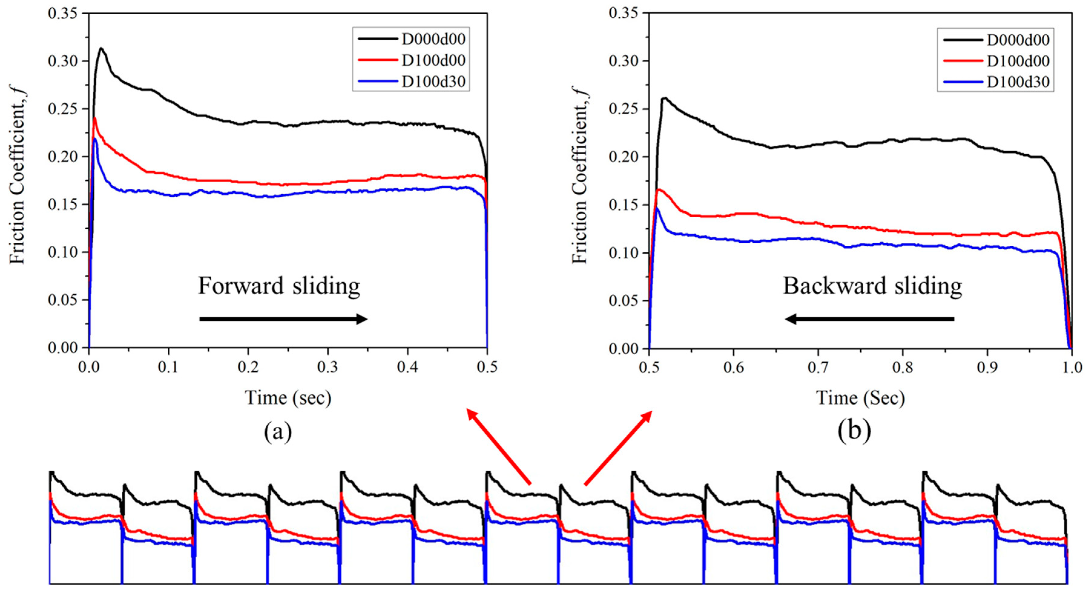
Figure 9 illustrates the temporal evolution of the friction coefficient during reciprocating sliding between Ti6Al4V discs with textured and untextured surfaces, and UHMWPE cylindrical pins under lubricated conditions. The test examines the run-in friction and wear conditions. The data were extracted from a stable region of a test with 1000 cycles and represent a single complete cycle, i.e., a forward and backward slide, to provide a vivid observation of the impact of various texture designs on friction and hydrodynamic lubrication.
From
Figure 9, it is evident that the friction coefficient varied throughout the entire cycle. Higher friction coefficients were observed at the beginning of both forward and backward slides, reaching a minimum around the middle where constant linear sliding speed occurs [
41]. Additionally, a similar friction evolution trend was noted between forward and backward slides, as depicted in
Figure 9a,b. However, consistently higher friction was observed during the forward slide compared to the backward slide in all cases. This phenomenon could be attributed to surface finish and the run-in condition between the contacting pairs.
In general, the surfaces with texture features exhibit lower friction coefficients compared to the untextured surfaces, attributed to intentionally designed and fabricated textures that boost hydrodynamic lubrication. The multiscale textures, in particular, achieved the lowest friction coefficient. Furthermore, on the textured surfaces, the friction coefficient reaches its lowest steady value within approximately 0.05 s after sliding begins, in contrast to the untextured surfaces, which reach the lowest steady friction coefficient value 0.20 s after sliding begins, as depicted in
Figure 9a. This indicates that the sliding begins in the boundary/mixed lubrication regime and transitions towards the hydrodynamic lubrication regime as the sliding velocity increases. For the multiscale textures, the instant reduction in friction coefficient signifies a rapid surge in lubricant film thickness caused by the buildup of hydrodynamic pressure due to the surface textures. The instantaneous drop in the friction coefficient for the multiscale textured surfaces illustrates how, under identical operating conditions, the multiscale texture features can increase the time spent in the hydrodynamic lubrication regime and decrease the time in the boundary/mixed lubrication regime compared to the untextured and only microscale textured surfaces. This effect reveals the potential of multiscale texture features for significant friction and wear reduction.
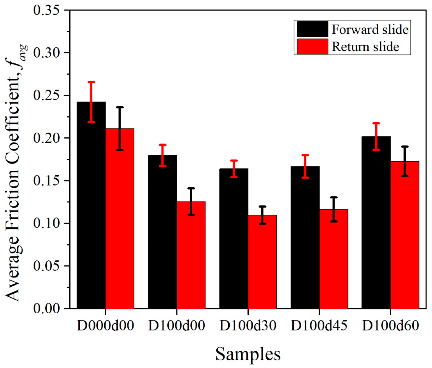
Table 4 lists the average friction coefficient for forward and backward sliding and indicating one standard deviation. Minimum friction coefficient was observed for D100d30 during both forward and backward slide.
Figure 10 illustrates the average friction coefficients of three types of multiscale textures compared to two reference samples—an untextured surface and just microscale textures. The untextured surface displays a higher friction coefficient in contrast to the textured surfaces with multiscale textures exhibiting the lowest fiction coefficient.
Forward sliding resulted in higher friction coefficient than return sliding for all tested conditions. In multiscale textures, the friction coefficient reduces as the size of the interstitial texture features decrease. In other words, decreasing the interstitial texture density reduces the friction coefficient. Accordingly, the experimental results align with the simulation outcomes, showing that an increase in lubricant film thickness increases the separation between articulating surfaces, leading to a reduction in the friction coefficient due to a decrease in solid-on-solid contact. However, when employing larger interstitial textures such as D100d60, multiscale textures may have a detrimental effect due to the absence of a sufficient load-carrying flat surface. Therefore, careful consideration of texture feature parameters is essential in the design of multiscale textures to achieve the desired results.
3.7. Wear Analysis of UHMWPE Pin Surface
The major challenge in metal on polymer (MOP) tribo-pairs for prosthetic hip implant is the wear of softer materials like UHMWPE. Utilizing a textured surface is a promising solution to reduce both friction and wear. To analyze wear mechanisms and assess the impact of multiscale surface textures on UHMWPE wear,
Figure 11 illustrates post-tribo-test images of the UHMWPE pins sliding against textured and untextured Ti6Al4V discs. Visible scratches appeared along the sliding direction of the UHMWPE surface. Various degrees of abrasive and adhesive wear were observed on the contacting surfaces of the UHMWPE pins, depending on the type of textured or untextured Ti6Al4V surface against which the pin slides. Three sample pins were selected because they represent the pins articulating with untextured, only microscale textured, and one from multiscale textured surface, which resulted in the lowest UHMWPE wear during the experiment.
The primary wear mechanism of the UHMWPE pin sliding on the smooth untextured surface, (D000d00) was abrasive wear and created deep scratches, as well as some adhesive wear as shown in
Figure 11a. In contrast, the pin sliding on just the microscale textured surface (D100d00) exhibits fewer and shallower scratch marks, indicating less damage by abrasive wear, as depicted in
Figure 11b. However, some noticeable adhesion marks are observed. The sample pin articulated with the multiscale textured surface (D100d30), shows faint wear marks compared to both untextured and just microscale textured surfaces (
Figure 11c). The original machining and polishing marks (not parallel to the sliding direction) are still clearly apparent on the UHMWPE pin surface after sliding against the multiscale textured surface (
Figure 11c) but have been largely worn off after sliding against the smooth surface (
Figure 11a). The change in wear mechanism is caused by the multiscale surface textures creating thicker lubricant films and trapping wear debris compared to the untextured surface. Similar results were observed in [
42,
43] where UHMWPE pins articulating with untextured and microtextured CoCrMo discs.
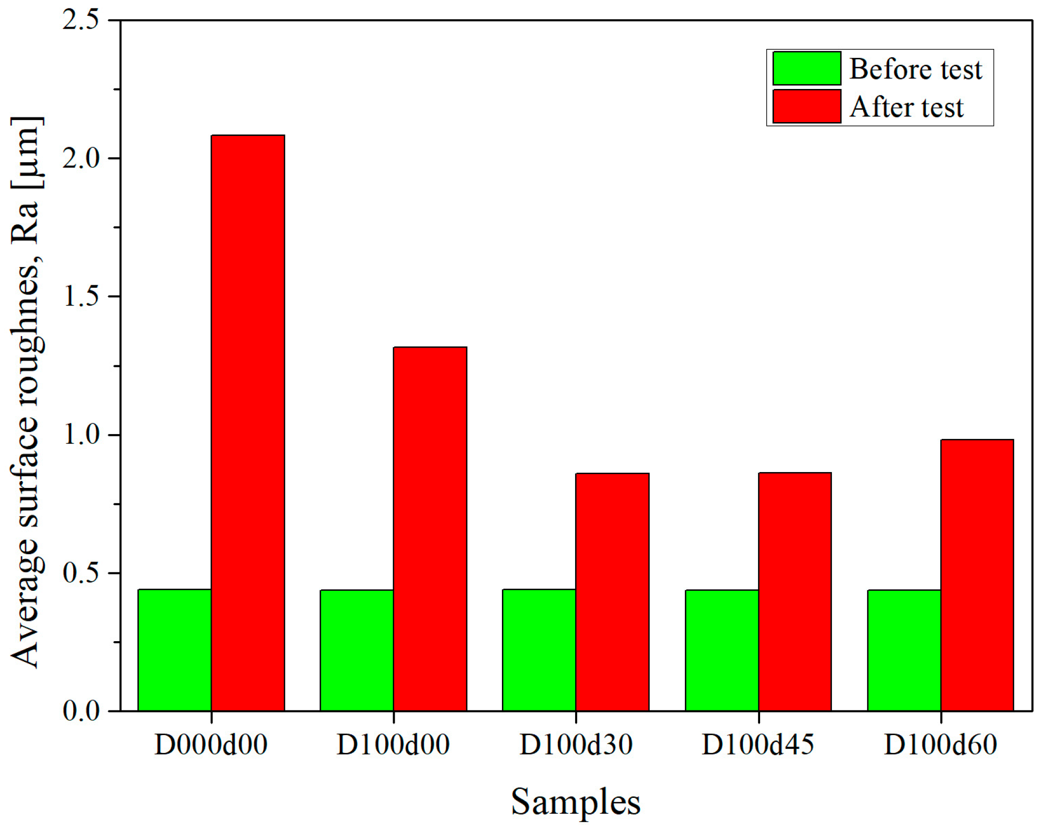
Figure 12 depicts the average surface roughness on the UHMWPE surface before and after the friction test. It is evident that the initial surface roughness (Ra 0.441 µm) of all pins increased after the pin-on-disc test due to the abrasive and adhesive wear damage. However, the change in surface roughness resulting from wear decreased by 58.7% for the multiscale textured surface D100d30 (Ra 0.859 µm), and by 36.74% for the only microscale textured surface D100d00 (Ra 1.317 µm), compared to the untextured surface D000d00 (Ra 2.082 µm). Within the multiscale textured surfaces, the change in surface roughness decreased as the texture density of interstitial textures reduced, aligning with both the friction coefficient and simulation results.
In conclusion, surface texturing, especially multiscale textures, shows potential in maximizing lubricant film thickness by improving wettability and hydrodynamic lubrication. This, in turn, increases the separation of tribo-pairs, resulting in low and stable friction coefficient, reduced wear of UHMWPE, and ultimately, a noticeable improvement in the longevity of prosthetic hip implants.
4. Limitation and Accuracy
The current work utilizes an HL model and reciprocating pin-on-disc experiments to study the effect of multiscale texture features on the surface of biocompatible materials as a first step to indicate the suitability of the multiscale surface texturing technique to increase the durability of prosthetic hip implants by reducing the friction and wear. There are several simplifications of the current methods that differ from a real prosthetic hip implant. For example, our simulations assume parallel sliding surfaces to model a small section of a spherical prosthetic hip implant. The current HL model does not consider bearing surface deformation, which differs from hard-on-soft bearing surfaces such as metal on polymer or ceramic on polymer prosthetic hip implants, wherein the soft polymer surface deforms significantly more than the hard bearing surface. However, prior elasto-hydrodynamic lubrication (EHL) simulations that included the deformation of the polymer bearing surface showed similar trends as reported here for optimal texture design parameters [
21,
22].
Additionally, the Reynolds equation includes several assumptions such as fully flooded lubricant supply, steady-state, and Newtonian lubricant behavior, that may not always exist in a dynamically changing prosthetic hip implant with shear-thinning synovial fluid lubrication. However, the trends indicated in this study will help to increase the lubricant film thickness, which will increase the percentage of the time that full-film hydrodynamic lubrication will carry the applied load and decrease the percentage of time that the mixed and/or boundary lubrication regimes allow solid-on-solid contact between the bearing surfaces.
The physical friction experiments are carried out with pin-on-disc test set up which employed a simplified disc geometry, small pin contact area and fewer degrees of freedom compared to actual prosthetic hip implants. Moreover, constant loading and speed operating conditions used in this study do not replicate the in vivo test condition. However, the pin-on-disc experiment is useful for fast- and low-cost testing prior to conducting extensive tests. The results reveal the potential of multiscale texturing of hip implant bearing surface in reducing friction and wear of UHMWPE. Therefore, future research should consider conducting long-duration wear tests under dynamic loading and speed conditions on a spherical geometry (femoral head) with multiscale texture features on the bearing surface. Because the simulation results are independent of specific materials, this multiscale surface texture design could be investigated for other biomedical materials, such as CoCrMo or stainless steel.


