Article

Investigation into the Heat Transfer Behavior of Electrostatic Atomization Minimum Quantity Lubrication (EMQL) during Grinding

1
College of Mechanical Engineering and Automation, Liaoning University of Technology, Jinzhou 121001, China
2
School of Materials Science and Engineering, Xi’an University of Technology, Xi’an 710048, China
3
School of Mechanical and Automotive Engineering, Qingdao University of Technology, Qingdao 266520, China
4
Engineering Research Center of Mechanical Testing Technology and Equipment (Ministry of Education), Chongqing University of Technology, Chongqing 400054, China
5
Shandong Dongyu Construction Machinery Co., Jining 272000, China
*
Author to whom correspondence should be addressed.
Lubricants 2024, 12(5), 158; https://doi.org/10.3390/lubricants12050158
Submission received: 26 March 2024 / Revised: 26 April 2024 / Accepted: 29 April 2024 / Published: 30 April 2024
(This article belongs to the Special Issue Tribological Properties of Biolubricants)

Abstract

:
Electrostatic atomization minimum quantity lubrication (EMQL) technology has been developed to address the need for environmentally friendly, efficient, and low-damage grinding of challenging titanium alloy materials. EMQL leverages multiple physical fields to achieve precise atomization of micro-lubricants, enabling effective lubrication in high temperature, high pressure, and high-speed grinding environments through the use of electric traction. Notably, the applied electric field not only enhances atomization and lubrication capabilities of micro-lubricants but also significantly impacts heat transfer within the grinding zone. In order to explore the influence mechanism of external electric field on spatial heat transfer, this paper first comparatively analyzes the grinding heat under dry grinding, MQL, and EMQL conditions and explores the intensity of the effect of external electric field on the heat transfer behavior in the grinding zone. Furthermore, the COMSOL numerical calculation platform was used to establish an electric field-enhanced (EHD) heat transfer model, clarifying charged particles’ migration rules between poles. By considering the electroviscous effect, the study reveals the evolution of heat transfer structures in the presence of an electric field and its impact on heat transfer mechanisms.

1. Introduction

The burgeoning growth of sophisticated machinery in the domains of aerospace, rail transportation, marine engineering, energy, and biomedicine has rendered the high-efficiency, precision, and low-damage machining of titanium alloy materials that are challenging to machinery indispensable in the realm of advanced manufacturing technology [1,2]. However, the force and heat in the titanium alloy cutting zone increase sharply during the cutting process (especially grinding) due to the alloy’s low thermal conductivity, low elastic modulus, and high chemical activity. This can easily result in issues with fast tool wear and a low material removal rate, which have a serious negative impact on surface quality and machining accuracy [3,4,5]. According to researchers’ studies, the contact length between a titanium alloy chip and a tool is extremely short—less than one-third that of a steel contact length under identical circumstances [6]. It is the primary source of temperature and stress concentration close to the cutting edge (within 0.5 mm), accelerating tool wear and deformation failure. P.A. Dearnley and A.N. Grearson [7] specifically examine the titanium alloy cutting zone’s temperature evolution behavior. It is discovered that because of the cutting zone’s excessively low thermal conductivity, heat cannot easily pass through the chip and the workpiece to the outside of the cutting system. This leads to a more significant accumulated temperature phenomenon and, ultimately, a decrease in the workpiece’s surface quality. It is evident that titanium alloy has a high requirement for a cutting environment, similar to other conventional hard-to-machine materials.
The traditional flooding lubrication method involves pouring a significant amount of cutting fluid (60 L/h) into the cutting zone to provide cooling, lubrication, chip removal, and rust prevention [8,9]. This method heavily relies on non-renewable resources like mineral oil, leading to the production of PM10 and PM2.5 suspended particles that pose risks to human health. Moreover, the cost of environmentally friendly post-processing of cutting fluid is high, indicating that this method does not align with the principles of green manufacturing [8,10]. Scholars have proposed various green lubrication processes, including solid lubrication, cryogenic cutting, and Minimum Quantity Lubrication (MQL). Cryogenic cutting, for instance, utilizes the phase-change heat absorption and strong convective heat transfer of low-temperature media such as liquid carbon dioxide (LCO2) and liquid nitrogen (LN2) to achieve rapid cooling in the high-temperature cutting zone. This method effectively suppresses the thermal softening effect of materials [11,12,13]. Numerous studies have demonstrated that utilizing cryogenic cutting, as opposed to traditional lubrication methods, can notably decrease the cutting zone temperature, resulting in a superior surface quality of the workpiece [14,15,16,17].
Furthermore, Hong and Zhao [18] emphasized that low-temperature media can substantially diminish the chemical reactivity between titanium and tool materials, preventing damage and failure due to tool overheating, and showing promise in enhancing tool longevity. However, challenges such as the high cost of cryogenic cutting, the extensive equipment requirements, temperature regulation complexities, limited lubrication capabilities, and susceptibility to microcrack formation in the workpiece hinder the widespread adoption of low-temperature processing in critical machining applications [12]. Minimum Quantity Lubrication (MQL) aims to minimize lubricant usage while still effectively cooling and lubricating the cutting zone, typically using only 30–100 mL/h per unit of grinding wheel width [19]. This technology has garnered significant attention in the realm of eco-friendly cooling and lubrication. Numerous studies have demonstrated that atomized micro-lubricant droplets, propelled by compressed air, can effectively cool and lubricate the cutting zone [20,21,22]. The issue of insufficient cooling performance has emerged in micro-lubrication technology due to the low thermal conductivity of the gas and the limited amount of liquid lubricant, particularly during the processing of challenging materials like titanium alloys. This problem has been highlighted in previous studies [23,24,25]. It is important to note that traditional MQL systems employ pneumatic atomization, with gas pressures typically ranging from 0.4–0.6 MPa. While higher gas pressures can enhance droplet transport and cooling efficiency, they also increase the risk of atomized droplets dispersing into the environment, posing potential health hazards to operators [26,27,28].
Scholars have proposed a novel technology called electrostatic atomization minimum quantity lubrication (EMQL) based on empirical evidence. This technology utilizes the combined effects of airflow and electrostatic fields to atomize and transport micro-lubricants into the cutting zone for cooling and lubrication purposes [29,30,31]. Bartolomeis [32] highlighted during the fifth CIRP CSI conference in 2020 that EMQL technology shows great promise for machining challenging materials in the aerospace industry. Research conducted by Shah and Huang [33,34] demonstrated that the application of an electric field can greatly enhance the atomization process of micro-lubricants, resulting in droplets with smaller average particle size, more uniform distribution, and improved penetration and adsorption capabilities. Gong and Lee P H [35,36], along with other researchers, conducted cutting experiments on titanium alloys. Their studies demonstrated that utilizing EMQL technology, as opposed to MQL conditions, not only enhances the surface quality of the workpiece but also notably prolongs the tool’s service life. The team conducted extensive research on EMQL technology, including the establishment of a mathematical model for the volume average particle size of atomized droplets from the electrostatic nozzle based on two-dimensional wave theory. They also examined the impact of the electrostatic field on the concentration of inhalable particles PM10/PM2.5 [37]. Furthermore, they conducted EMQL grinding experiments on titanium alloy, revealing the lubrication mechanism of the charged micro-lubricant electric traction film in the grinding zone. They determined the optimal electrical and aerodynamic parameters [5]. Interestingly, their study found that EMQL not only enhances atomization characteristics to improve lubrication ability but also appears to enhance the heat transfer capacity of the cutting zone. Su [38] and other researchers also noted this intriguing phenomenon in their study. The mechanism by which EMQL improves the cooling performance in the cutting zone remains undisclosed. To address this gap, this study conducted titanium alloy grinding experiments under dry, MQL, and EMQL conditions. Through measuring the grinding temperature and analyzing the surface quality of the machined surface, it was established that the electric field applied in EMQL had additional heat transfer effects beyond lubricant heat transfer in the cutting zone. To delve deeper into the heat transfer phenomenon of the applied electric field, a mathematical model of the EHD electric field-enhanced heat transfer temperature field was developed. The study tracked the evolution of the spatial temperature field under the influence of the applied electric field, revealing the enhanced heat transfer mechanism of the corona ion wind at the oil film and its interface. This research aims to bridge theoretical gaps and offer theoretical guidance for further exploration of EMQL technology.

2. Experimental Methodology

In this experiment, soybean oil was used as a micro-lubricant to grind titanium alloys under dry grinding, MQL and EMQL conditions and the temperature of the grinding zone then measured, compared, and analyzed the surface quality of the workpiece under various lubrication conditions.

2.1. Experiment and Measuring Device

The grinding and associated measuring equipment used in this experiment are shown in Figure 1.
The experiment used a K-P36 CNC precision surface grinding machine Shanghai Silaifulin Co., Ltd. (Shanghai, China) and a CBN grinding wheel with a particle size of 80#. The experiment provides a gas-liquid two-phase fluid for the electrostatic nozzle (self-made) through the Bluebe (Fuji, Japan) micro-lubrication system. The electrostatic nozzle is connected with a high-voltage DC power supply Dongguan Hongda Spraying Machinery Co., Ltd. (Dongguan, China) through the high-voltage cable to realize the high-voltage power supply, and the maximum voltage can reach 60 kV. The surface tension of soybean oil was measured by a BZY-201 surface tension meter. The dynamic viscosity of pure soybean oil was measured by a DV-2T viscometer produced by Brookfield Company (New York, NY, USA). The conductivity of pure soybean oil was measured by a DDS-307A conductivity measuring instrument produced by Shanghai Leici Company (Shanghai, China). The droplet charge-mass ratio of soybean oil under the condition of 0.3 MPa pressure and 30 kV was measured by a custom Faraday bucket and an EST111 picoammeter. The temperature measurement of the grinding zone adopts the clamped thermocouple method, and the thermocouple signal collector model is MX 100.

2.2. Experimental Materials

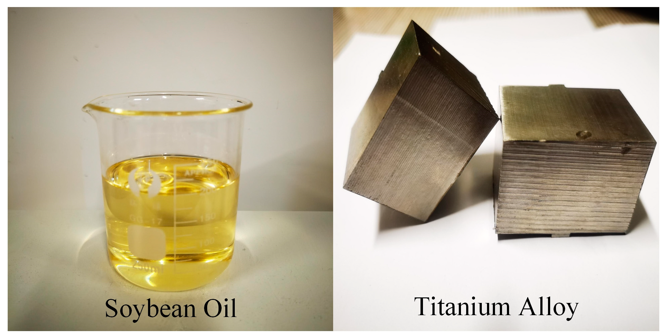
The EMQL base oil used in the experiment is soybean oil, the workpiece material is (α + β) titanium alloy (20 mm × 20 mm × 30 mm), and the grade is Ti-6Al-4V, as shown in Figure 2.
The main physical properties of titanium alloy Ti-6Al-4V are shown in Table 1:
The main components of soybean oil are fatty acids, including saturated fatty acids (SFA), myristic acid (C14:0), palmitic acid (C16:0), stearic acid (C18:0) and arachidic acid (C20:0); monounsaturated fatty acids (MUFA), oleic acid (C18:1) and arachidonic acid (C20:1); polyunsaturated fatty acids (PUFA), linoleic acid (C18:2) and linolenic acid (C18:3), as shown in Table 2, and the rest are types of components that are not detected. Relevant studies have shown that polar groups such as -COOH, -COOR, etc., in soybean oil and metal surface molecules rely on van der Waals forces to form a physical adsorption film, which can play a role in lubrication and friction reduction. In addition, there is also chemical adsorption between soybean oil and metal surface, also known as the metal saponification reaction, forming a chemical adsorption film. It also has a certain role in lubrication and friction reduction, so soybean oil is an ideal biodegradable MQL base oil [42,43].
The surface tension of soybean oil at room temperature was 32.17 mN/m, the dynamic viscosity was 61.14 cP, the conductivity of soybean oil was 0.54 mS/m, and the droplet charge–mass ratio of soybean oil was 0.2634 mC/kg under the pressure of 0.3 MPa and the voltage of 30 kV.

2.3. Experimental Parameters

The lubrication parameter settings under three working conditions are shown in Table 3:
Table 4 displays the other grinding parameters that are consistent in each group, with the exception of the lubrication condition, to ensure experiment consistency.

3. Results and Discussion

3.1. Grinding Temperature Analysis

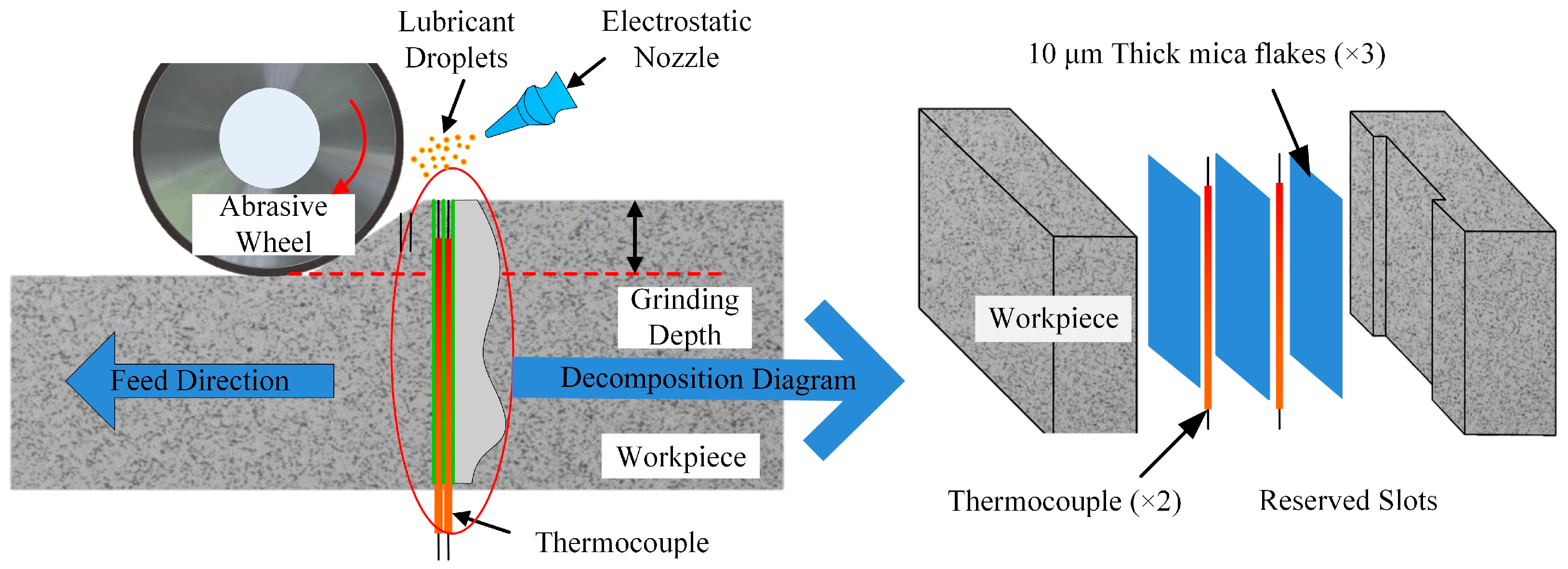
Experimental measurements of the grinding zone’s temperature were made under dry grinding, MQL, and EMQL conditions. Figure 3 illustrates the clamped thermocouple method of measurement.
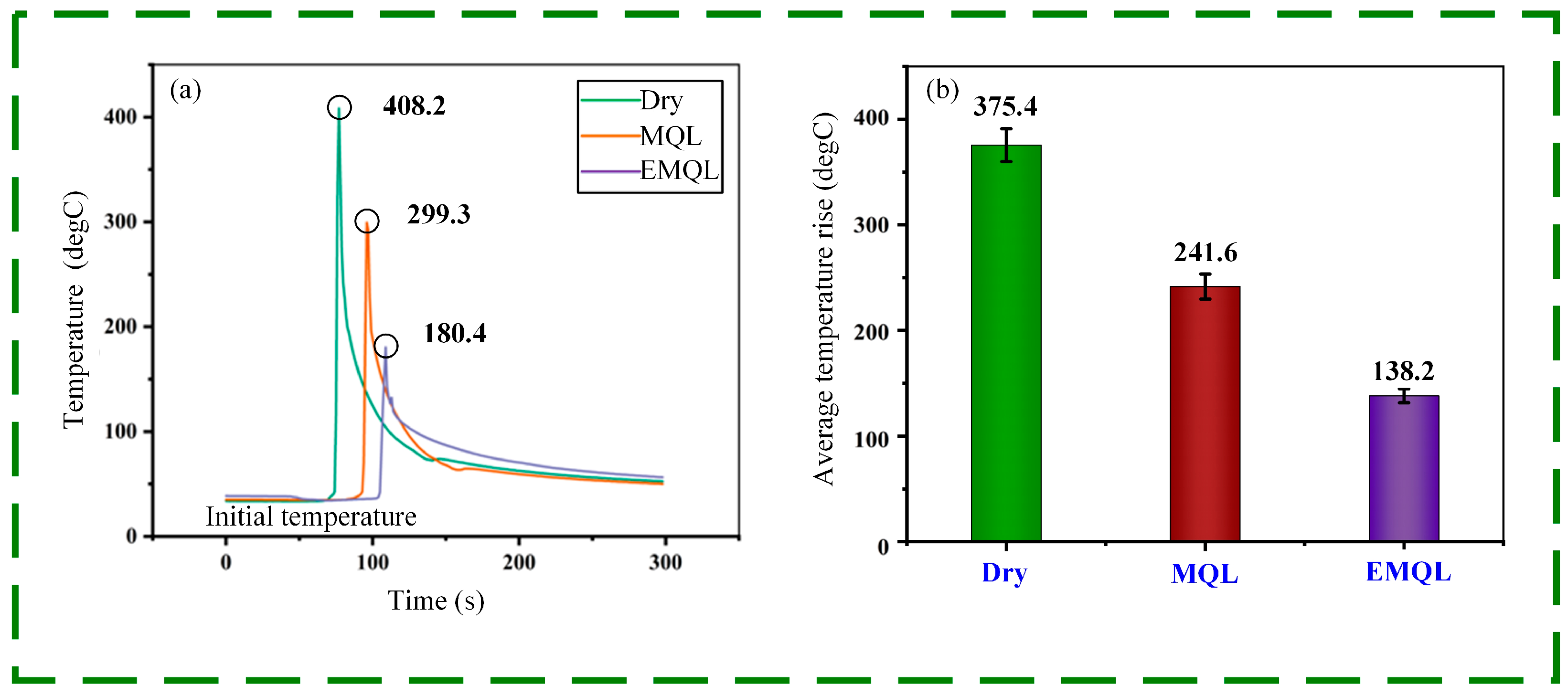
The single temperature peak curve measured under the three working conditions is shown in Figure 4a. The single temperature peaks obtained under dry grinding, MQL and EMQL conditions are 408.2 °C, 299.3 °C, and 180.4 °C, respectively. As illustrated in Figure 4b, ten temperature curve peaks are gathered for mean processing for each working condition, and the initial temperature value is subtracted to determine the mean temperature rise under each working condition. The mean temperature rise of the workpiece surface under dry grinding condition is 375.4 °C, under an MQL condition is 241.6 °C, and under an EMQL condition is 138.2 °C. It is evident that in dry grinding conditions, there is no cooling medium to assist in the machining process. As a result, a significant amount of grinding heat will build up in the grinding zone and cannot be rapidly dispersed to the surrounding area. Furthermore, in dry grinding conditions, there is more friction between the abrasive wheel and the workpiece, increasing the amount of heat produced in the grinding zone. A thorough investigation reveals that the grinding zone’s temperature is highest when grinding is dry. In the case of MQL, the rise in the grinding zone’s temperature is greater than that of EMQL. The reason is that only the quick flow of compressed air during the MQL process can facilitate heat transfer in the grinding zone. Despite having a higher heat transfer capacity than dry grinding, MQL still has a certain shortfall in this area because of the gas’s low thermal conductivity. The surface temperature rise of the workpiece under EMQL condition is only 36.8% of that under dry grinding conditions, which shows that the external electric field has an obvious heat transfer effect on the grinding zone. Compared with the other two types of processing conditions, the EMQL method is ideal for the heat transfer capacity of the grinding zone.

3.2. Surface Quality Evaluation

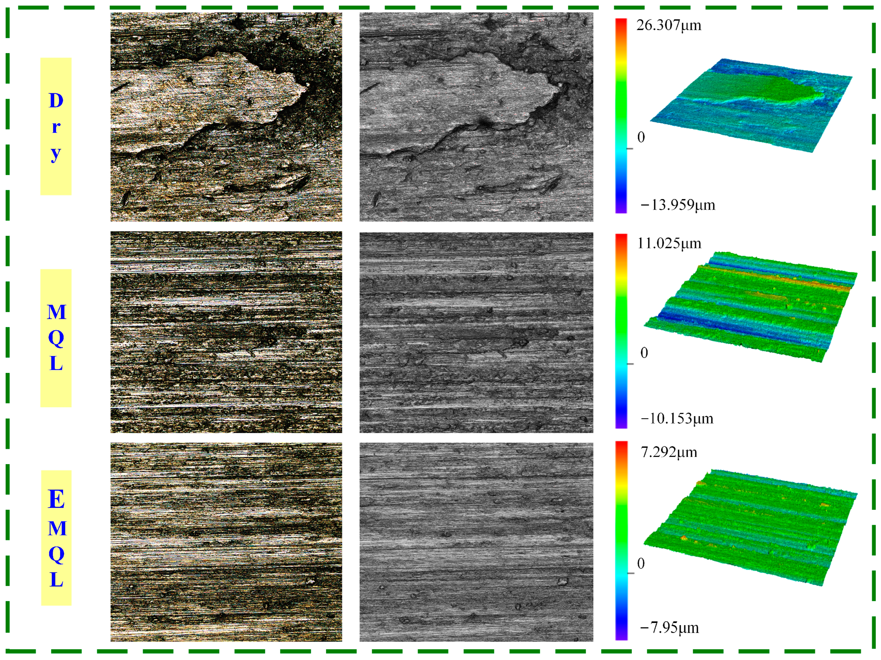
The surface morphology of the workpiece under different lubrication conditions was observed by a laser confocal microscope. Figure 5 is the typical surface morphology under three lubrication conditions. From left to right, the color map, intensity map and height map under the corresponding working conditions are in turn. It can be seen that the surface quality of the workpiece is very poor under dry grinding conditions, and a large area of chip adhesion occurs on the surface under high temperatures. The bonding force between the adhesion layer and the matrix material is insufficient, and it is easy to fall off under the action of external force. The adhesion layer has a significant impact on the workpiece’s performance because it will even remove some of the matrix material when it falls off. Furthermore, the dry grinding surface exhibits very noticeable deep grooves and large-area bulk material peeling, which contribute to the workpiece’s poor surface quality. The height map shows that the dry grinding surface’s maximum height difference in the observation area can reach 40.266 μm. The analysis suggests that the sharp rise in temperature in the grinding zone during dry grinding of titanium alloy, combined with its low thermal conductivity, significantly increases the material’s plasticity. This, coupled with high pressure, leads to continuous chip adhesion between the grinding wheel and workpiece surface, ultimately forming an adhesion layer. This results in adhesive wear on the workpiece surface, leading to unsatisfactory surface quality in dry grinding.
The value of workpiece surface roughness also decreases, and no large area chip adhesion phenomenon was seen on the surface position under MQL grinding conditions. However, the workpiece’s surface was clearly contaminated by multiple granular adhesions, and the furrow made by the abrasive machining process lacked regularity. According to the analysis, under MQL conditions, the high-speed compressed air flow can disturb the surrounding gas around the grinding zone, thereby removing some of the heat. Furthermore, the heat exchange within the grinding zone is positively impacted by the penetration of micro-lubricants. As a result, the workpiece’s surface quality and the cooling conditions of the grinding zone both improve.
Under the EMQL condition, the surface quality of the workpiece is the highest, the maximum height difference in the scanning area is only 15.242 μm, the number and size of adhesion points are reduced, and the distribution of furrows is the most uniform. It is evident that the workpiece’s surface quality under EMQL conditions is clearly superior to that under the other two conditions. The analysis demonstrates that the external electric field intervention improves the micro-lubricant’s atomization characteristics. It can improve the charged droplets’ ability to migrate and penetrate the grinding zone’s microchannel, in addition to raising the lubricant’s effective utilization rate [5]. Therefore, the grinding zone obtains a more ideal cooling and lubrication effect. In comparison to MQL, the heat accumulation is lower during the machining process, resulting in a surface temperature of the workpiece that is insufficient to create extensive chip adhesion. As a result, a significant reduction in adhesion points and layers on the workpiece surface is observed.
The aforementioned study findings unequivocally support the beneficial impact of the applied electric field on the grinding zone’s heat dissipation. However, more information is required to fully understand the heat transfer mechanism of the applied electric field in space. This paper investigates the mechanism of action of charged particles’ heat transfer behavior through numerical calculation based on the objective reality that such behavior is difficult to verify through experiments.

4. Model of Electric Field-Enhanced Heat Transfer

4.1. Theoretical Model of Electric Field-Enhanced Heat Transfer

The electric field-enhanced heat transfer process studied in this article belongs to the category of electrohydrodynamics, which specifically involves the coupling synergies of two-phase flow field, electric field, and temperature field. Based on the motion pattern of liquid film and gas-liquid two-phase flow, the physical equation of two-phase flow is constructed. Considering the applied electric field and the electric field near the electrode, the physical equation of the electrostatic field is constructed. Furthermore, based on the two-phase flow and electrostatic field equations and combined with the heat transfer energy conservation equation, the theoretical model of EHD electric field-enhanced heat transfer is established.
(1) Governing equation of electrostatic field
When the motion speed of charge is much less than the speed of light, if the dielectric fluid is incompressible, the basic equation of electrohydrodynamics can be obtained according to Maxwell’s equations and Gauss’s law. The Poisson equation of the electric field intensity distribution is E at the electrode, which can be expressed as follows:
ε E = q e
where ε is the dielectric constant (F/m) and qe is the charge density (C/m3).
The relationship between electric field intensity E and electric potential V can be expressed as follows:
E = V
The equation of charge conservation is:
J + q e t = 0
where J is the current density (A/m2) and t is the time (s).
In the corona discharge drift region, the current density consists of the conduction term, convection term and diffusion term. The conduction term is the current density generated by the movement of ions under the action of the electric field, the convection term is the current density generated by ions under the action of the fluid flow, and the diffusion term is the current density generated by the uneven distribution of ions in space. The current density equation obtained by combining the above three items is:
J = q e χ E + q e u D q q e
where χ is the ionic mobility in the electric field, Dq is the ionic diffusion coefficient, and u is the velocity vector of the flow field. Compared with the conduction term, the convection term and diffusion term are relatively small and negligible, so Equation (4) can be simplified as follows:
J = q e χ E = σ E
where σ is the conductivity of the heat transfer medium (S/m).
When the current is stable in the corona discharge process, the second term of Equation (3) is zero, and combined with Equation (5), we can obtain:
J = ( σ E ) = E σ + σ E = 0
Then we can get:
σ E = E σ
This can be obtained from Equation (1):
ε E = q e E ε
Combinations (7) and (8), we can get:
q e = E ε ε σ E σ
(2) Governing equation of two-phase flow field
Both the gas and liquid phases in the calculation region satisfy the mass conservation equation:
u = 0
The mass conservation equation is also known as the fluid continuity equation, where u is the velocity vector (m/s), and based on the assumption that the fluid is incompressible, the internal velocity gradient of each phase is 0.
Based on Newton’s second law, the principle of keeping the total momentum of gas-liquid two phases unchanged in the process of motion and considering pressure, viscous force, gravity and applied electric field force, the momentum conservation equation can be obtained as follows:
ρ ( u t + u u ) = ρ g P + μ 2 u + F e
where ρ u t is the time-varying acceleration term, ρ u u is the displacement change acceleration term, ρ g is the gravitational term, P is the pressure gradient term, μ 2 u is the viscous force term, and F e is the electric field force term.
(3) Multi-physics coupling equation
It can be seen from the summary analysis that the process of EHD electric field-enhanced heat transfer is a coupling heat transfer problem of the flow field, electric field, and temperature field, in which the influence of the electric field on fluid motion is reflected in the electric field force term in Equation (11). The force of the particle in the fluid in the electric field can be expressed as follows:
F e = q e E 1 2 E 2 ε + 1 2 ρ E 2 ( ε ρ ) T
The first term on the right of Equation (12) is the electrophoretic force term (also known as the Coulomb force term), which represents the force exerted by the electric field on the free charge in the fluid, the direction of which depends mainly on the direction of the electric field and the polarity of the free charge. The second term on the right is the dielectrophoresis force term, which is the force exerted on the fluid by the electric field caused by the gradient of the dielectric constant. Due to the large difference in the dielectric constant between the gas phase and the liquid phase, this force is more obvious at the gas-liquid two-phase interface. The third term on the right is the electrostrictive force term, which is mainly caused by the uneven distribution of electric field strength and the change of dielectric constant density gradient.
When the heat transfer medium is a non-polar fluid, the following relationship exists:
1 2 ρ E 2 ( ε ρ ) T ε 0 ( ε r 1 ) ( ε r + 2 ) 6 E 2 + ε 0 E 2 6 ( ε r 1 ) ( ε r + 2 )
In this case, the electric field force can be written as a sub-term as follows:
F e = F 1 + F 2 + F 3 + F 4
Of which:
F 1 = q e E = ( E ε ε σ E σ ) E
F 2 = 1 2 E 2 ε
F 3 = ε 0 ( ε r 1 ) ( ε r + 2 ) 6 E 2
F 4 = ε 0 E 2 6 ( ε r 1 ) ( ε r + 2 )
Under the action of electric field strengthening, the convection heat transfer term of the electric field should be introduced into the fluid energy equation, and the energy equation can be obtained by ignoring the fluid compression work and viscous dissipation energy:
T t + u T = λ ρ c p 2 T + σ E 2 ρ c p
where λ is the thermal conductivity (W/(m·K)) and cp is the specific heat capacity at constant pressure (J/(kg·K)).

4.2. Geometric Model of Electric Field-Enhanced Heat Transfer

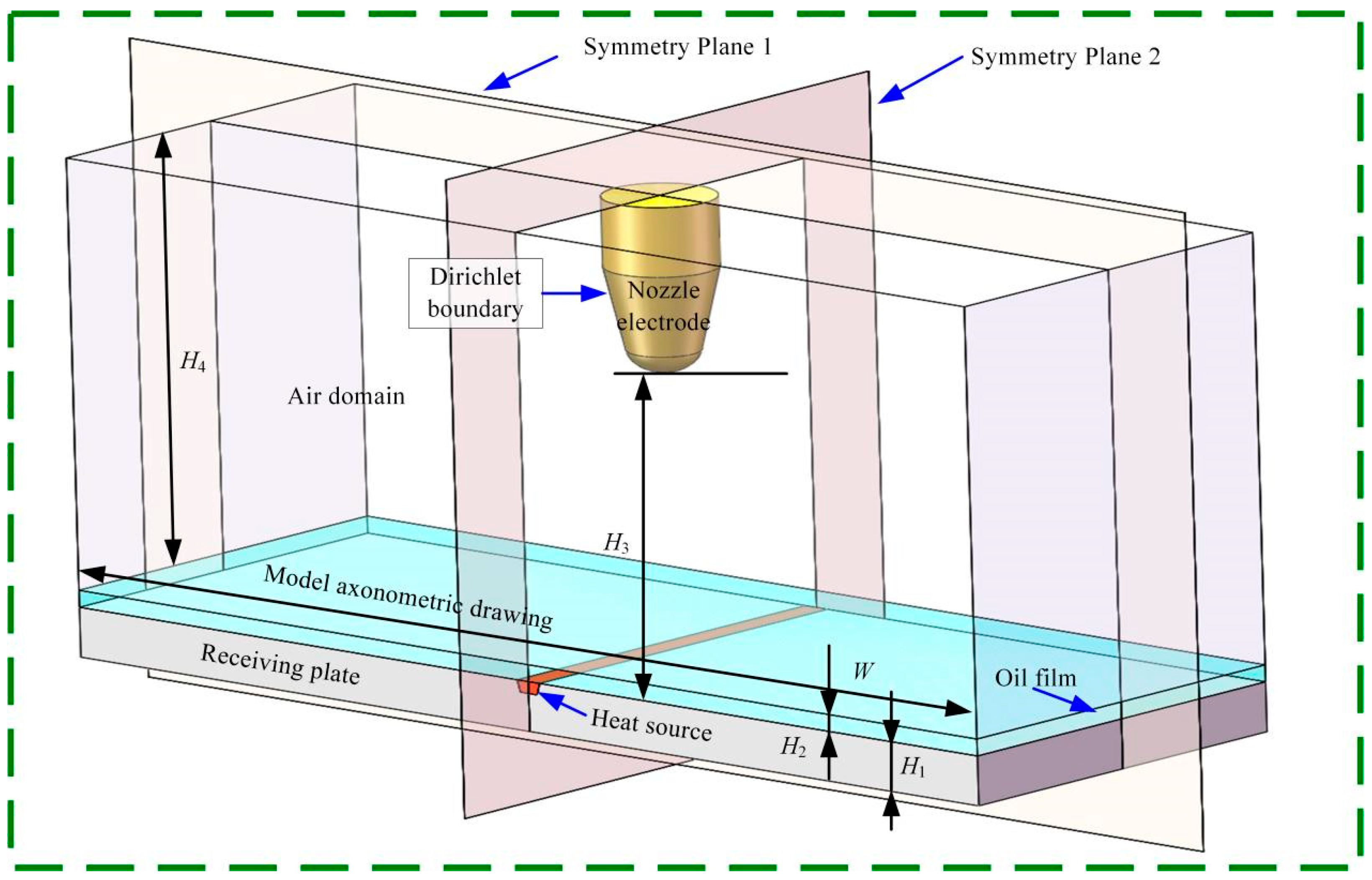
The EMQL nozzle used in the research is a contact nozzle. The nozzle can charge more than just the liquid phase during the spraying process. Simultaneously, it forms a needle plate electrode structure with the workpiece’s surface as a high-voltage electrode. Consequently, the formation of an ion wind and the corona discharge phenomenon will disrupt the spatial flow field and enhance its heat transfer efficiency. Make the three-dimensional geometric model depicted in Figure 6; a receiving plate grounded and positioned at the bottom of the model has a thickness of H1 = 2 mm. A trapezoidal linear heat source is positioned in the center of the receiving plate’s upper surface, and the bottom and outer edges are thermally insulated. It is employed to mimic the steady heat source found in grinding. An oil film covering the receiving plate is present; its thickness is H2 = 2 mm. The air domain is situated above the oil film, with a height of H4 = 27 mm and a width of W = 50 mm. The nozzle electrode is positioned exactly above the heat source, with H3 = 20 mm separating its bottom from the receiving plate’s upper surface. Two symmetry planes are placed on the model to lessen the calculation amount; as a result, the actual calculation amount is only one-fourth of the model’s actual size.
The boundary conditions of the model are established based on the multi-physical field-solving conditions and the model’s true physical meaning. Firstly, according to the properties of the flow field, the left and right sides and the upper boundary of the air domain are set as the fluid outlet, and the geometric lower boundary is set as the Navier sliding wall. The heat source is set to a constant value K0, meaning it never decays and always maintains the same temperature. The oil film is set to soybean oil, and the electrode material is set to copper. The nozzle is set to meet the Dirichlet boundary condition with an initial voltage of V0, and its value can be set independently based on the model’s calculation conditions. This further sets the electric field boundary condition. Charge conservation is applied to all calculation areas other than the nozzle electrode.

4.3. Current Density Distribution Characteristics Analysis

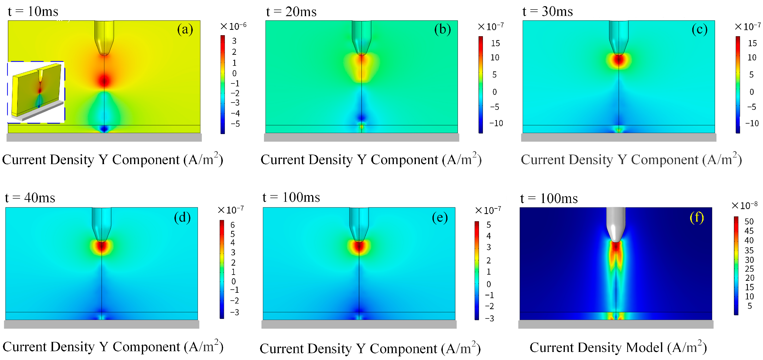
In EMQL, the workpiece and the charged nozzle are connected to the positive and negative poles of the DC high-voltage power supply, respectively. In this configuration, the charged nozzle can be approximated as a curved electrode needle, forming a needle-plate electrode structure with the workpiece. Due to the significant difference in curvature between the electrode needle and the flat electrode below, the resulting electric field is non-uniform, making it prone to corona discharge at the tip of the needle with a small curvature. Under a 30 kV condition, the spatial current density Y component on the symmetric plane 1 is depicted in Figure 7. Figure 7a–e represent the current density at 10, 20, 30, 40, and 100 ms, respectively. It can be observed that during the initial stage of corona formation, a substantial amount of space charge accumulates beneath the nozzle electrode and moves toward the receiving plate. In the region facing the oil film on the nozzle electrode, charges of opposite polarity are induced and migrate towards the nozzle electrode. At this stage, the positive and negative charges have not yet been encountered, resulting in a space current density of up to 10−6 A/m2. Subsequently, at 20 ms, some space charges with different polarities meet and neutralize each other, leading to a decrease in space current density and an approximate level of 10−7 A/m2. At 30 ms and 40 ms, the spatial current density distribution stabilizes, remaining the same as that at 100 ms. Hence, it can be concluded that the space current density reaches a stable state within 30–40 ms after the corona occurs, and thereafter, it fluctuates within a small range, which is attributed to random charge collisions. Figure 7f illustrates the current density model on the symmetric plane 1 at 100 ms. Notably, space charges exhibit faster movement near the nozzle electrode and at the position directly below the oil film. Due to the notable difference in charge mobility between the oil film and the surrounding air, a fault in the space current density arises at the interface between these two phases.
During the corona discharge process, the corona region is usually accompanied by complex micro-particle electrochemical reactions such as ionization, recombination, and adsorption, generating a large number of positive and negative ions. These charged ions and free electrons continue to accelerate to the ground electrode under the action of the electric field. Due to the viscous effect, the medium around the motion path can be obviously disturbed to form ionic wind (electric field-induced secondary flow) and accompanied by energy transfer, thus destroying the boundary layer between the phase interfaces. Therefore, it can take away more heat and effectively improve the heat transfer capacity of the heat transfer medium.

4.4. Study on Temperature Field of Electric Field-Enhanced Heat Transfer

The convective heat transfer model under the condition of an electric field and the natural convection heat transfer model are constructed in order to further investigate the impact of space current density change on temperature under the action of an electric field. The heat transmission capacity of EMQL technology is examined by contrasting the temperature fields of the two heat transfer modes.
The oil film and air domain temperatures were set to 20 °C at room temperature, whereas the constant temperature heat source temperature was set to 100 °C. The temperature nephogram of oil film heat transfer by natural convection in the absence of an electric field is shown in Figure 8. It can be seen that the heat transfer efficiency of oil film is very low without external disturbance. Even when the time reaches 2000 ms, the temperature of the oil film diffuses to the interface between the oil film and air.
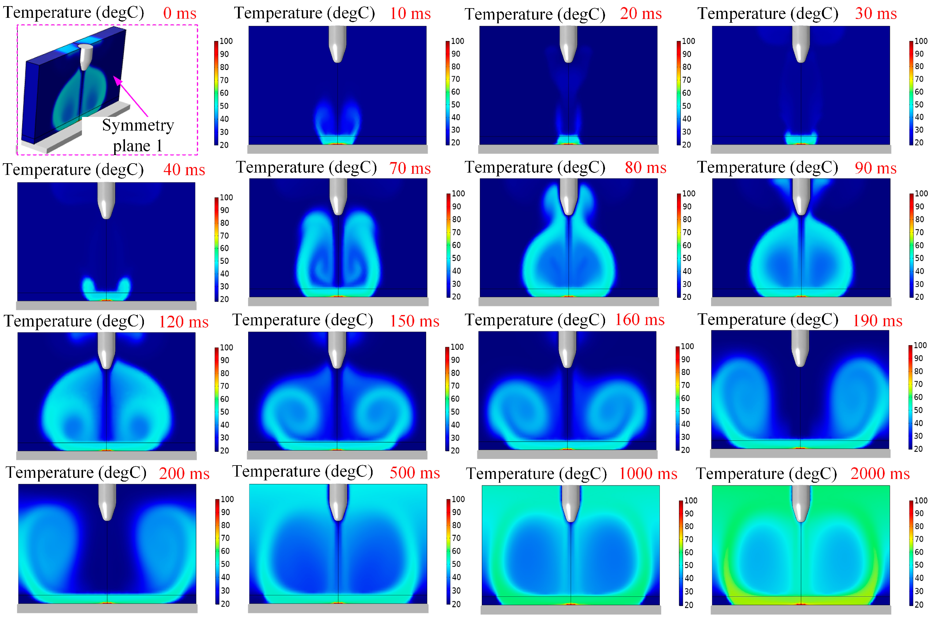
The temperature field of 30 kV electric field-enhanced heat transfer is shown in Figure 9. It is evident that the heat source is maintained above 100 °C at 0 ms at the start of the computation, and the gas phase and liquid phase regions are unaffected by the electric field. The distribution of temperatures over space is in line with heat transmission through natural convection. The induced charges begin to build at the oil film just below the nozzle electrode and ascend at 10 ms. The flow field and the oil layer around it are disturbed when there is local negative pressure, and this causes the heat source temperature to disperse quickly. It is evident that the temperature field diffusion interface has exceeded the initial interface of the two-phase flow at this time, indicating that the temperature diffusion response speed is extremely fast under the action of the electric field. The heat transfer intensity at 10 ms has surpassed the heat transfer intensity of natural convection heat transfer at 2000 ms. Additionally, a significant temperature gradient is observed at the gas-liquid two-phase interface due to the difference in thermal conductivity between the gas and liquid phases. At 20 ms, the charged particles generated by the electrode collide with the upwardly moving induced charged particles, triggering a series of complex electrochemical reactions. In this process, a certain amount of energy is consumed, weakening the negative pressure below to some extent and consequently reducing the heat diffusion intensity. The central flow field generated by the nozzle electrode penetrates the central axis at 30 ms. At 40–70 ms, a double vortex arm structure is formed on both sides of the heat transfer zone and gradually approaches the nozzle electrode. At this stage, the vortex motion can effectively expand the heat transfer space. At 80 ms, the heat transfer space of the temperature field has been extended to the outside of the nozzle electrode, and the heat transfer area presents a jellyfish shape. During the period of 90–150 ms, the heat transfer zone always maintains a jellyfish-like structure. However, with the increase of time, an internal eddy current is formed on both sides of the central flow field, and the eddy current intensity increases and expands to both sides. At 160 ms, the original jellyfish structure was destroyed due to the expansion of the internal vortex, and a new butterfly structure was formed. At this time, the heat transfer zone was separated from the nozzle electrode. Subsequently, the eddy current intensity continues to increase and gradually expands outward, reaching the edge of the computational domain at 190 ms. Throughout the development of the heat transfer zone, the eddy current intensity exhibits an increasing trend, indicating that the flow field disturbance is increasing, the heat transfer performance in the calculation domain is gradually improving, and the heat transfer space is gradually increasing. By tracking the temperature field distribution at 500 ms, 1000 ms, and 2000 ms, it can be observed that due to the limitation of the calculation boundary and the development of the eddy current, the eddy current arm reaches the vicinity of the nozzle electrode again at 500 ms, forming an annular heat transfer structure. Then, the shape remains unchanged, but the thickness of the vortex arm increases with time, and the accumulated heat in space also increases.
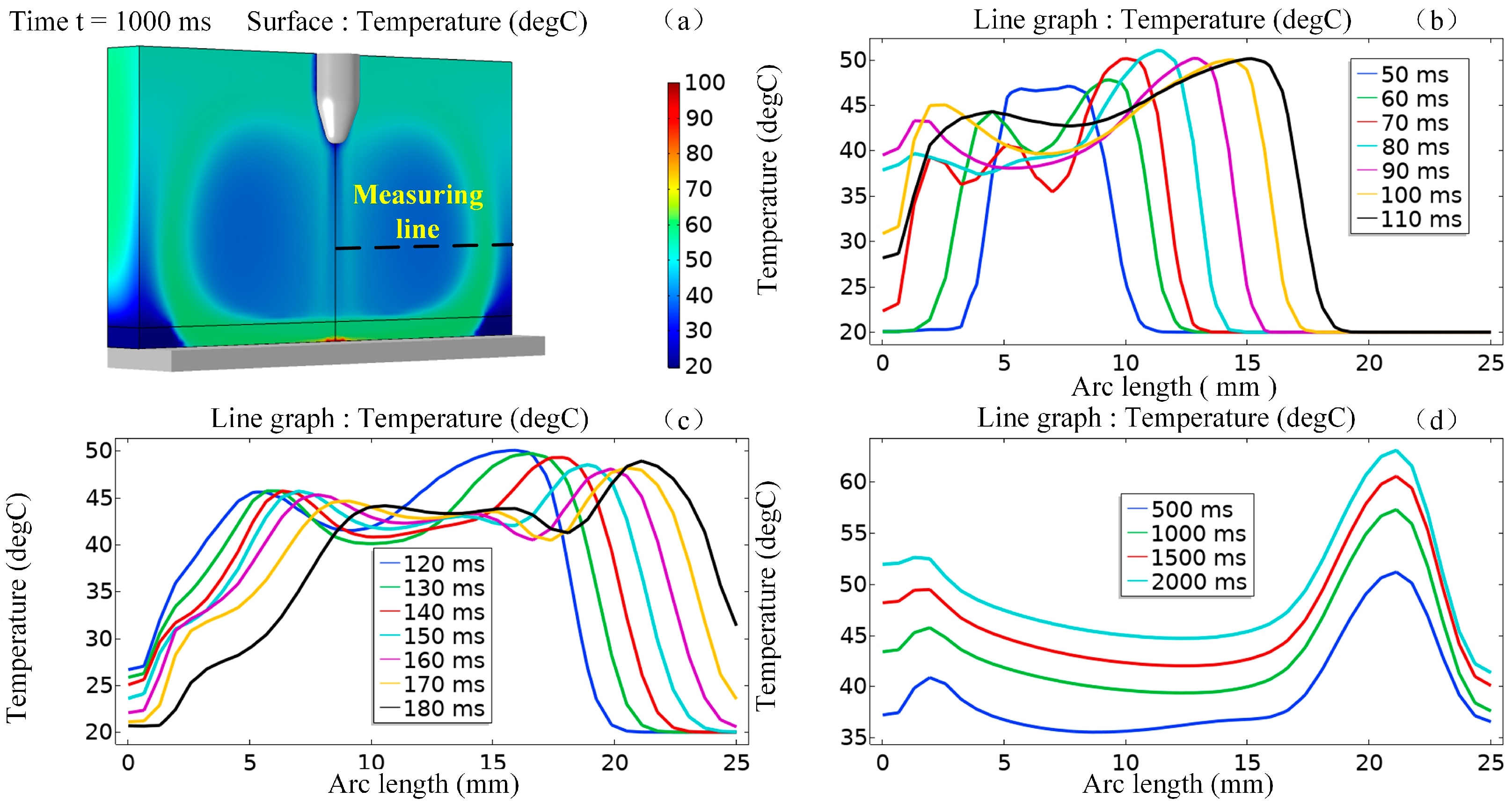
As shown in Figure 10a, the horizontal measurement line is drawn on symmetrical plane 1, and the temperature curves at different times on the measurement line are traced as shown in Figure 10b–d. Figure 10b is the temperature curve on the horizontal measurement line corresponding to the 50–110 ms time node. It can be seen that with the increase of time, the temperature influence area continues to expand to both sides, which is consistent with the development trend of the above vortex arm. Due to the interaction between the vortex arm and the nozzle electrode at 70 ms and 80 ms, the temperature curve fluctuates irregularly. The peak temperature increased during 50–90 ms, but decreased slightly at 100 ms and 110 ms. The analysis suggests that it may be due to the expansion of the temperature-affected zone. Figure 10c shows the temperature curve on the horizontal measurement line corresponding to the 120–180 ms time node. This stage corresponds to the process of the temperature-affected zone from jellyfish to butterfly in Figure 9. It can be found that the temperature distribution is relatively stable during the transformation process, and its overall shape has not changed, but it shows the law of moving right as a whole with time. It can be seen that the temperature in the peak area reaches almost 50 °C, which also shows that the electric field has a very obvious improvement in the heat transfer capacity of the flow field. Figure 10d is the temperature distribution curve on the horizontal measurement line of the heat transfer stable area. It can be seen that the temperature distribution in the heat transfer stable area is generally consistent, but the heat transfer area continues to widen with the increase of time, and the peak temperature continues to increase. The peak temperature exceeds 60 °C at 2000 ms.

5. Conclusions

Comparative grinding experiments were conducted on titanium alloy Ti-6Al-4V under dry, MQL, and EMQL conditions. By measuring the grinding temperature and analyzing the surface quality, the heat transfer capacity of the grinding zone under different operating conditions was compared and analyzed. Furthermore, the strengthening mechanism of the applied electric field on the heat transfer of the lubricating oil film in the grinding zone was explored through numerical simulation.
(1) The average surface temperature rise of the titanium alloy Ti-6Al-4 grinding workpiece was measured under dry grinding, MQL, and EMQL conditions. The results showed that the minimum surface average temperature rise was 138.2 °C under the EMQL condition, which decreased by 63.2% and 42.8% compared to dry grinding and MQL, respectively. This confirms the effectiveness of EMQL in enhancing heat transfer during the grinding process.
(2) The surface morphology of the workpiece under the three operating conditions was compared and analyzed. The results indicate that the surface quality of the workpiece is optimal under the EMQL condition. The second is the MQL grinding condition, and no adhesion layer is observed on its surface, but there are obvious multiple granular adhesion pollutions, and the regularity of the furrows created during the abrasive machining process is poor. Under the condition of dry grinding, the surface quality of the workpiece is the worst—a large area of an adhesion layer appears, yet a whole clear furrow can barely be observed.
(3) Based on the electrostatic field control equation, two-phase flow field control equation, and multi-physical field coupling equation, a numerical calculation model of EHD electric field-enhanced heat transfer was constructed. The evolution of current density distribution and temperature field distribution over time was explored. The results show that: ① Compared to natural convection heat transfer, the applied electric field can significantly improve the spatial heat transfer capacity; ② After the corona occurs, the spatial current density will reach a stable state within 30–40 ms, but random charge collisions will cause the spatial current density to fluctuate within a small range; ③ The peak temperature of the spatial heat transfer exceeds 60 °C at 2000 ms under the action of the external electric field.

Author Contributions

Experimental operation and data statistics, Z.H.; experimental data processing, D.J.; theoretical model establishment of electric field-enhanced heat transfer, Y.Z.; establishment of the physical model of the electric field-enhanced heat transfer, D.Q.; simulation data analysis, Z.L.; draft editing and review, E.Z. All authors have read and agreed to the published version of the manuscript.

Funding

This study was financially supported by the China Postdoctoral Science Foundation Funded Project (Grant No. 2023M732826), Liaoning Provincial Science and Technology Program Project (Grant No. 2023JH1/10400074), Special Fund of Taishan Scholars Project (Grant No. tsqn202211179), and the Natural Science Foundation of Chongqing, China [grant number 2022NSCQMSX2038].

Data Availability Statement

The data presented in this study are available on request from the corresponding author. The data are not publicly available due to privacy or ethical restrictions.

Acknowledgments

The author thanks Zhenjing Duan for the COMSOL simulation platform provided.

Conflicts of Interest

Erjun Zeng was employed by Shandong Dongyu Construction Machinery Co. The authors declare no conflicts of interest.

References

  1. Rao, B.; Dandekar, C.R.; Shin, Y.C. An experimental and numerical study on the face milling of Ti–6Al–4V alloy: Tool performance and surface integrity. J. Mater. Process Technol. 2011, 211, 294–304. [Google Scholar] [CrossRef]
  2. Cui, C.X.; Hu, B.M.; Zhao, L.C.; Liu, S.J. Titanium alloy production technology, market prospects and industry development. Mater. Des. 2011, 32, 1684–1691. [Google Scholar] [CrossRef]
  3. Veiga, C.; Davim, J.P.; Loureiro, A.J.R. Review on machinability of titanium alloys: The process perspective. Rev. Adv. Mater. Sci. 2013, 34, 148–164. [Google Scholar]
  4. Hong, S.Y.; Markus, I.; Jeong, W. New cooling approach and tool life improvement in cryogenic machining of titanium alloy Ti-6Al-4V. Int. J. Mach. Tools Manuf. 2001, 41, 2245–2260. [Google Scholar] [CrossRef]
  5. Jia, D.Z.; Li, C.H.; Zhang, Y.B.; Yang, M.; Cao, H.J.; Liu, B.; Zhou, Z.M. Grinding performance and surface morphology evaluation of titanium alloy using electric traction bio micro lubricant. Chin. J. Mech. Eng. 2022, 58, 198–211. [Google Scholar]
  6. Dvivedi, A.; Kumar, P. Surface quality evaluation in ultrasonic drilling through the Taguchi technique. Int. J. Adv. Manuf. Technol. 2007, 34, 131–140. [Google Scholar] [CrossRef]
  7. Dearnley, P.A.; Grearson, A.N. Evaluation of principal wear mechanisms of cemented carbides and ceramics used for machining titanium alloy IMI 318. Mater. Sci. Technol. 1986, 2, 47–58. [Google Scholar] [CrossRef]
  8. Wang, Y.; Liu, C.F. State-of-the-art on minimum quantity lubrication in green machining. J. Clean. Prod. 2023, 429, 139613. [Google Scholar] [CrossRef]
  9. Irani, R.A.; Bauer, R.J.; Warkentin, A. A review of cutting fluid application in the grinding process. Int. J. Mach. Tools Manuf. 2005, 45, 1696–1705. [Google Scholar] [CrossRef]
  10. Gunter, K.L.; Sutherland, J.W. An experimental investigation into the effect of process conditions on the mass concentration of cutting fluid mist in turning. J. Clean. Prod. 1999, 7, 341–350. [Google Scholar] [CrossRef]
  11. Shokrani, A.; Dhokia, V.; Muñoz-Escalona, P.; Newman, S.T. State-of-the-art cryogenic machining and processing. Int. J. Comput. Integr. Manuf. 2013, 26, 616–648. [Google Scholar] [CrossRef]
  12. Gupta, K.; Laubscher, R.F. Sustainable machining of titanium alloys: A critical review. Proceedings of the Institution of Mechanical Engineers. Proc. Inst. Mech. Eng. Part B J. Eng. Manuf. 2017, 231, 2543–2560. [Google Scholar] [CrossRef]
  13. Kaynak, Y.; Gharibi, A. Progressive tool wear in cryogenic machining: The effect of liquid nitrogen and carbon dioxide. J. Manuf. Mater. Proc. 2018, 2, 31. [Google Scholar] [CrossRef]
  14. Dhananchezian, M.; Pradeep Kumar, M. Cryogenic Turning of the Ti–6Al–4V Alloy With Modified Cutting Tool Inserts. Cryogenics 2011, 51, 34–40. [Google Scholar] [CrossRef]
  15. Jebaraj, M.; Pradeep Kumar, M. Effect of cryogenic CO2 and LN2 coolants in milling of aluminum alloy. Mater. Manuf. Process. 2019, 34, 511–520. [Google Scholar] [CrossRef]
  16. Hong, S.Y.; Ding, Y. Cooling approaches and cutting temperatures in cryogenic machining of Ti-6Al-4V. Int. J. Mach. Tools Manuf. 2001, 41, 1417–1437. [Google Scholar] [CrossRef]
  17. Shakeel Ahmed, L.; Govindaraju, N.; Pradeep Kumar, M. Experimental investigations on Cryogenic cooling in the drilling of titanium alloy. Mater. Manuf. Process. 2016, 31, 602–607. [Google Scholar]
  18. Hong, S.Y.; Zhao, Z.B. Thermal aspects, material considerations and cooling strategies in cryogenic machining. Clean Prod. Process. 1999, 1, 107–116. [Google Scholar] [CrossRef]
  19. Wu, X.F.; Xu, W.H.; Ma, H.; Zhou, Z.M.; Liu, B.; Cui, X.; Li, C.H. Mechanism of Electrostatic Atomization and Surface Quality Evaluation of 7075 Aluminum Alloy under Electrostatic Minimum Quantity Lubrication Milling. Surf. Technol. 2023, 52, 337–350. [Google Scholar]
  20. Ramana, S.V.; Ramji, K.; Satyanarayana, B. Influence of nano-level variation of solid lubricant particle size in the machining of AISI 1040 steel. Int. J. Mater. Eng. Innov. 2011, 2, 16–29. [Google Scholar] [CrossRef]
  21. Sun, J.; Wong, Y.S.; Rahman, M.; Wang, Z.G.; Neo, K.S.; Tan, C.H.; Onozuka, H. Effects of coolant supply methods and cutting conditions on tool life in end milling titanium alloy. Mach. Sci. Technol. 2006, 10, 355–370. [Google Scholar] [CrossRef]
  22. Rahim, E.A.; Sasahara, H. Investigation of tool wear and surface integrity on MQL machining of Ti-6AL-4V using biodegradable oil. Proc. Inst. Mech. Eng. Part B J. Eng. Manuf. 2011, 225, 1505–1511. [Google Scholar] [CrossRef]
  23. Tascioglu, E.; Gharibi, A.; Kaynak, Y. High speed machining of near-beta titanium Ti-5553 alloy under various cooling and lubrication conditions. Int. J. Adv. Manuf. Technol. 2019, 102, 4257–4271. [Google Scholar] [CrossRef]
  24. He, T.; Liu, N.C.; Xia, H.Z.; Wu, L.; Zhang, Y.; Li, D.G.; Chen, Y. Progress and trend of minimum quantity lubrication (MQL): A comprehensive review. J. Clean. Prod. 2023, 386, 135809. [Google Scholar] [CrossRef]
  25. Huang, S.Q.; Lv, T.; Wang, M.H.; Xue, X.F. Enhanced machining performance and lubrication mechanism of electrostatic minimum quantity lubrication-EMQL milling process. Int. J. Adv. Manuf. Technol. 2018, 94, 655–666. [Google Scholar] [CrossRef]
  26. Lv, T.; Xu, X.F.; Yu, A.B.; Hu, X.D. Oil mist concentration and machining characteristics of SiO2 water-based nano-lubricants in electrostatic minimum quantity lubrication-EMQL milling. J. Mater. Process Technol. 2021, 290, 116964. [Google Scholar] [CrossRef]
  27. Xu, X.F.; Lv, T.; Luan, Z.Q.; Zhang, Y.Y.; Wang, M.H.; Hu, X.D. Capillary penetration mechanism and oil mist concentration of Al2O3 nanoparticle fluids in electrostatic minimum quantity lubrication (EMQL) milling. Int. J. Adv. Manuf. Technol. 2019, 104, 1937–1951. [Google Scholar] [CrossRef]
  28. Liu, N.C.; Zou, X.; Yuan, J.; Jiang, H.; Zhang, Y.; Chen, Y. Optimization of MQL turning process considering the distribution and control of cutting fluid mist particles. Int. J. Adv. Manuf. Tech. 2021, 116, 1233–1246. [Google Scholar] [CrossRef]
  29. Lv, T.; Huang, S.Q.; Hu, X.D.; Feng, B.H.; Xu, X. Study on Aerosol Characteristics of Electrostatic Minimum Quantity Lubrication and Its Turning Performance. Chin. J. Mech. Eng. 2019, 55, 129–138. [Google Scholar] [CrossRef]
  30. Yuan, S.M.; Zhu, G.Y.; Wang, L. Recent Progress on Lubricant Characteristics of Minimum Quantity Lubrication (MQL) Technology in Green Cutting. Chin. J. Mech. Eng. 2017, 53, 131–140. [Google Scholar]
  31. Huang, S.Q.; Wang, Z.; Yao, W.Q.; Xue, X.F. Tribological evaluation of contact-charged electrostatic spray lubrication as a new near-dry machining technique. Tribol. Int. 2015, 91, 74–84. [Google Scholar] [CrossRef]
  32. Bartolomeis, A.D.; Newman, S.T.; Shokrani, A. Initial. investigation on Surface Integrity when Machining Inconel 718 with Conventional and Electrostatic Lubrication. Procedia CIRP 2020, 87, 65–70. [Google Scholar] [CrossRef]
  33. Shah, P.; Gadkari, A.; Sharma, A.; Shokrani, A.; Khanna, N. Comparison of machining performance under MQL and ultra-high voltage EMQL conditions based on tribological properties. Tribol. Int. 2021, 153, 106595. [Google Scholar] [CrossRef]
  34. Huang, S.Q. A Study on Lubrication-Cooling Mechanisms and Machining Characteristics of Electrostatic Minimum Quantity Lubrication (EMQL). Ph.D. Thesis, College of Mechanical Engineering Zhejiang University of Technology, Hangzhou, China, June 2018. [Google Scholar]
  35. Gong, L. Investigation on The Lubricating Performance and Mechanism of Electrostatic Atomization Cutting Using Micro Oil-Based Nanofluids. Ph.D. Thesis, Jiangsu University of Science and Technology, Zhenjiang, China, June 2016. [Google Scholar]
  36. Lee, P.H.; Kim, J.W.; Lee, S.W. Experimental characterization on eco-friendly micro-grinding process of titanium alloy using air flow assisted electrospray lubrication with nanofluid. J. Clean. Prod. 2018, 201, 452–462. [Google Scholar] [CrossRef]
  37. Jia, D.Z.; Li, C.H.; Liu, J.H.; Zhang, Y.B.; Yang, M.; Gao, T.; Shubham Sharma, Z.S. Prediction model of volume average diameter and analysis of atomization characteristics in electrostatic atomization minimum quantity lubrication. Friction 2023, 11, 2107–2131. [Google Scholar] [CrossRef]
  38. Chen, D.D. Research on Cooling Performance and Mechanism of Micro-Waterbased Nanofluid Electrostatic Spray. Ph.D. Thesis, Jiangsu University of Science and Technology, Zhenjiang, China, June 2016. [Google Scholar]
  39. Ezugwu, E.O.; Wang, Z.M. Titanium alloys and their machinability—A review. J. Mater. Process Technol. 1997, 68, 262–274. [Google Scholar] [CrossRef]
  40. Sadeghi, M.H.; Haddad, M.J.; Tawakoli, T.; Emami, M. Minimal quantity lubrication-MQL in grinding of Ti–6Al–4V titanium alloy. Int. J. Adv. Manuf. Technol. 2009, 44, 487–500. [Google Scholar] [CrossRef]
  41. Gajrani, K.K. Assessment of cryo-MQL environment for machining of Ti-6Al-4V. J. Manuf. Process. 2020, 60, 494–502. [Google Scholar] [CrossRef]
  42. Zhang, Y.B.; Li, C.H.; Yang, M.; Jia, D.Z.; Wang, Y.G.; Li, B.K.; Hou, Y.L.; Zhang, N.Q.; Wu, Q.D. Experimental evaluation of cooling performance by friction coefficient and specific friction energy in nanofluid minimum quantity lubrication grinding with different types of vegetable oil. J. Clean. Prod. 2016, 139, 685–705. [Google Scholar] [CrossRef]
  43. Guo, S.M.; Li, C.H.; Zhang, Y.B.; Wang, Y.G.; Li, B.K.; Yang, M.; Zhang, X.P.; Liu, G.T. Experimental evaluation of the lubrication performance of mixtures of castor oil with other vegetable oils in MQL grinding of nickel-based alloy. J. Clean. Prod. 2016, 140, 1060–1076. [Google Scholar] [CrossRef]
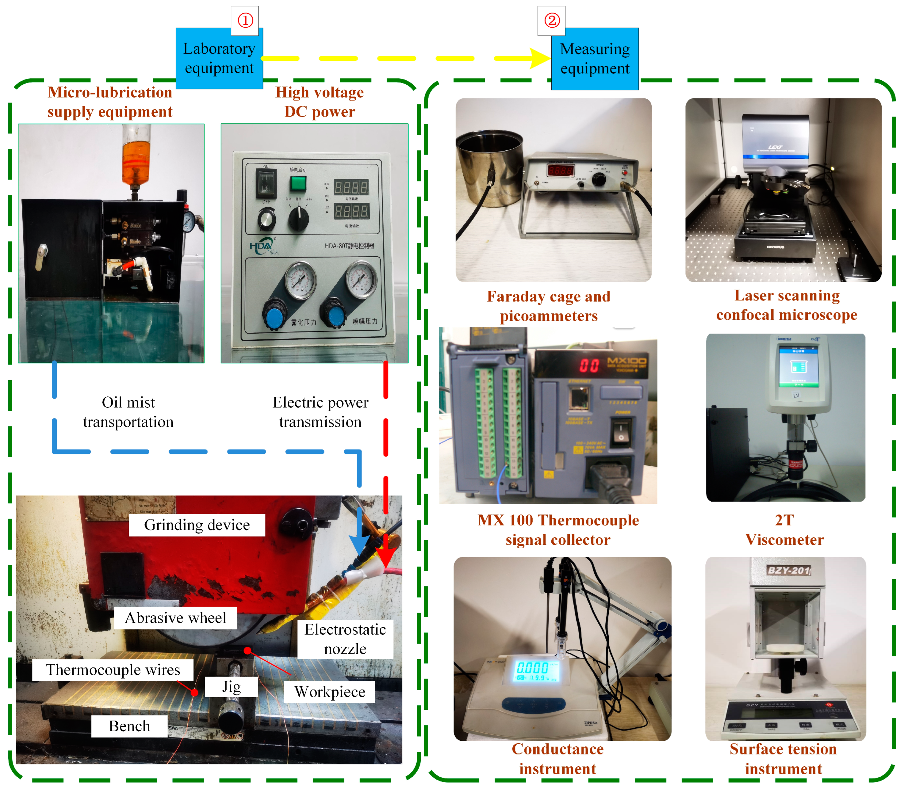
Figure 1. Grinding machining and measuring equipment.
Lubricants 12 00158 g001
Figure 2. Experimental materials.
Lubricants 12 00158 g002
Figure 3. Thermocouple clamp measurement method.
Lubricants 12 00158 g003
Figure 4. Temperature measurement curve and average temperature rise diagram. (a) Temperature measurement curve; (b) Mean temperature rise of grinding zone under different working conditions.
Lubricants 12 00158 g004
Figure 5. Surface morphology of workpiece under different lubrication conditions.
Lubricants 12 00158 g005
Figure 6. Geometric model of heat transfer enhanced by an electric field.
Lubricants 12 00158 g006
Figure 7. Distribution of current density in model space. (a) The current density Y component at t = 10 ms; (b) The current density Y component at t = 20 ms; (c) The current density Y component at t = 30 ms; (d) The current density Y component at t = 40 ms; (e) The current density Y component at t = 100 ms; (f) The current density model at t = 100 ms.
Lubricants 12 00158 g007
Figure 8. Cloud image of temperature under natural convection heat transfer conditions.
Lubricants 12 00158 g008
Figure 9. Temperature cloud image under 30 kV electric field-enhanced heat transfer condition.
Lubricants 12 00158 g009
Figure 10. Temperature curve of the horizontal direction at 30 kV. (a) Geometric model of heat transfer enhanced by an electric field and measuring line; (b) The temperature curve of 50 ms to 110 ms in the horizontal direction; (c) The temperature curve of 120 ms to 180 ms in the horizontal direction; (d) The temperature curve of 500 ms to 2000 ms in the horizontal direction.
Lubricants 12 00158 g010
Table 1. Physical property of Ti-6Al-4V [39,40,41].
Thermal
Conductivity
(W/m·K)
Specific
Heat
(J/kg·K)
Density
(g/cm3)
Elastic
Modulus
(GPa)
Poisson
Ratio
Yield
Strength
(MPa)
Tensile
Strength
(MPa)
7.955526.34.421140.342880950
Table 2. Contents of various fatty acids in soybean oil.
C14:0C16:0C18:0C18:1C18:2C18:3C20:0C20:1SFAMUFAPUFA
0.0610.303.7822.3050.845.900.290.3614.9222.8757.83
Table 3. Lubrication parameters under different lubrication conditions.
Lubrication ConditionsLubrication Parameters
Dry cutting-
MQLLiquid flow rate: 60 mL/h; Pressure: 0.3 MPa; Nozzle angle: 15°; Jet distance: 30 mm
EMQLLiquid flow rate: 60 mL/h; Pressure: 0.3 MPa; Nozzle angle: 15°; Jet distance: 30 mm; Voltage: 30 kV
Table 4. Grinding parameters.
Grinding ParameterValues
Grinding wheel speed vs. (m/s)30
Feed rate VW (m/min)3.5
Grinding depth ap (μm)10
Cutting modeRectangular path plane grinding
Disclaimer/Publisher’s Note: The statements, opinions and data contained in all publications are solely those of the individual author(s) and contributor(s) and not of MDPI and/or the editor(s). MDPI and/or the editor(s) disclaim responsibility for any injury to people or property resulting from any ideas, methods, instructions or products referred to in the content.