Article

Lubrication Modeling of the Reciprocating Piston with High Lateral Load and Various Conditions in a Swash Plate-Type Piston Pump

1
Department of Mechanical System Engineering, Dongguk University-WISE Campus, Gyeongju-si 38066, Republic of Korea
2
Korea Institute of Science and Technology Information, Daejeon 34141, Republic of Korea
*
Author to whom correspondence should be addressed.
Lubricants 2024, 12(2), 55; https://doi.org/10.3390/lubricants12020055
Submission received: 5 January 2024 / Revised: 26 January 2024 / Accepted: 15 February 2024 / Published: 16 February 2024

Abstract

:
Most asymmetrical lateral forces occur in the reciprocating piston mechanism, which is widely applied as a major component of power equipment. When this lateral force greatly acts on the piston, it comes into contact with the cylinder. To prevent this negative phenomenon, lubrication characteristic evaluation and control technology are necessary. In this study, a boundary lubrication model considering the elastic deformation of the contact surface was adopted to perform a lubrication analysis of a piston hydraulic pump widely used in the aviation and plant industries. The piston/cylinder mechanism was analyzed in terms of contact force, characteristic thickness, and power loss while varying various design and operating parameters (friction coefficient, clearance, profiling shape, operating speed, and pressure). In the overall bearing capacity to withstand the tilt of the piston, the bearing capacity ratio due to contact at the interface increased more steeply than the bearing capacity ratio in the fluid lubrication area. Profiling of the piston head played a positive role in reducing power loss but also increased piston tilt. This trend appeared more clearly as the head profiling degree of processing Increased. Lastly, the effects of variable operating speed and pressure were examined. High operating speed caused low contact force, and high operating pressure caused high contact force. Through this study, it was possible to predict the lubrication performance and power loss of reciprocating piston pumps used in the field more realistically through appropriate boundary lubrication modeling.

Graphical Abstract

1. Introduction

Pistons are the most important operating elements in reciprocating piston machines, as the performance of such machines is ultimately dependent on the proper behavior of the pistons [1,2,3]. So far, the main areas of interest in this research have involved the optimal selection of the machining clearance [4], design materials [5], piston shape [6,7,8], groove shape [9], etc. One of the computational barriers to this type of work is the metallic contact or mixed/boundary lubrication by the exact tribological term. Fang and Shirakashi [10] experimentally showed that such contact often occurred. Pelosi and Ivantysynova [11] presented a method that considered the fluid–structure interaction between the piston and the cylinder wall. In the analysis of mechanical systems, FSI analysis, which simultaneously performs structural analysis and fluid dynamics analysis, is being performed in various ways. FSI analysis is applied to the analysis of cylinders [12], various bearings [13,14,15], and valves [16] to perform analysis close to actual phenomena. Yamaguchi [17] and Manring [18] both investigated the physical model of the boundary lubrication. Recently, wear analysis studies [19,20,21] have been conducted, and machine tribologists concur that the boundary lubrication regime should be taken into consideration. The authors’ previous study also proposed a boundary lubrication model for general piston machines [22]. The calculation model was developed while referring to the simplified contact model proposed by Hamrock and Brewe [23] and is expected to be useful for quickly and more realistically predicting the piston/cylinder lubrication behavior of a piston whose physical mechanism has not been Identified exactly. In addition, Richardson et al. conducted an analytical and experimental investigation of the motion of valve plates to evaluate the appropriate lubrication performance of axial piston pumps [24,25]. Moreover, an analysis of the movement of the piston in the lubrication system was also conducted considering various factors. Previous studies include analysis considering secondary motion [26,27], analysis considering bending of the piston rod and crosshead motion [27], multiphase flow analysis using VOF (volume of fluid) considering thermodynamic features [28], and analysis of the piston at high temperature and pressure in diesel engine [3]. In a recent study on a part connected with a reciprocating piston, Li et al. investigated the lubrication characteristics of a slipper pair in a large displacement or high-pressure piston pump [29]. As mentioned earlier, several approximations have been proposed for different lubrication regimes, including hydrodynamic, mixed, and boundary lubrication. This study specifically focuses on investigating the sliding parts of the piston/cylinder in a swash plate-type piston pump under various conditions, utilizing the elastic boundary lubrication model. The expectation is that the proposed model and parametric studies will offer efficient design guidance, particularly when pump designers need to account for material deformation and wear.

2. System Description

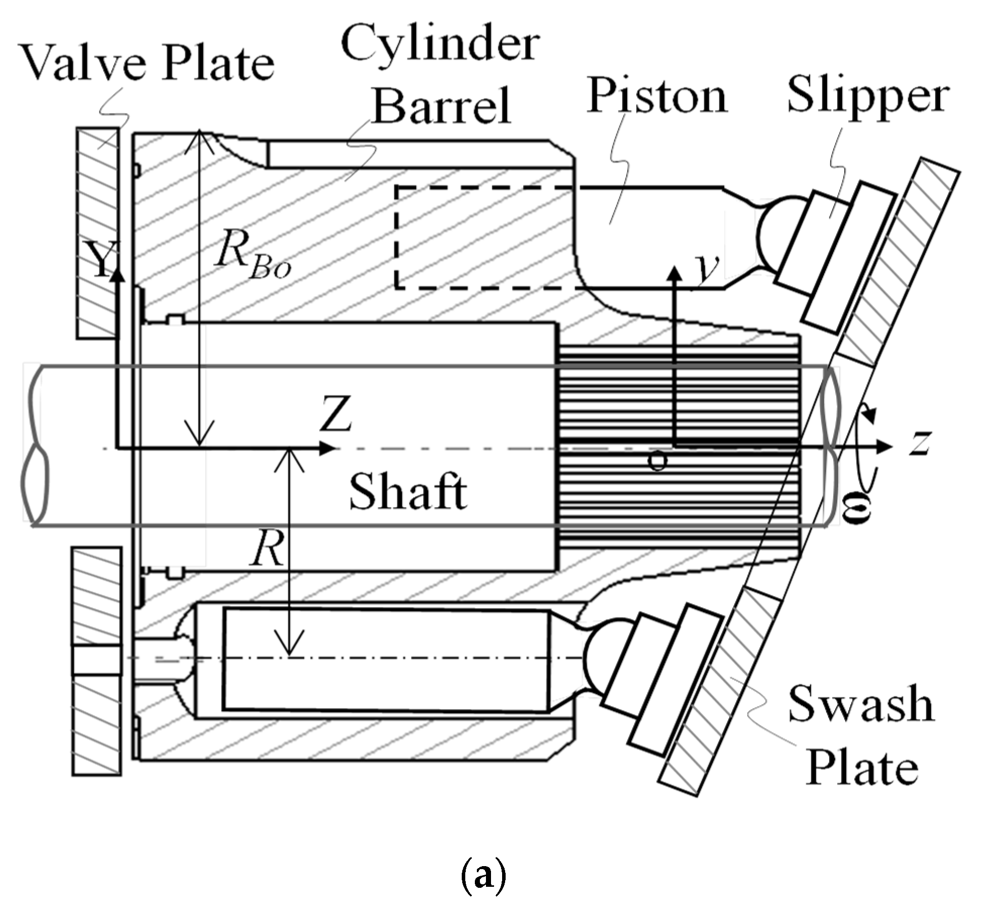
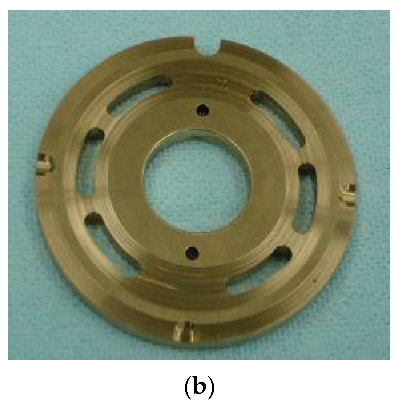
Figure 1 depicts the concerned piston/cylinder sliding mechanism. This kind of mechanism is very widely employed in various machines such as engines and hydraulic pumps. A representative one is the swash plate-type piston pump, which is the target machine in this paper and is shown in Figure 2. The word ‘lateral load’, which means force perpendicular to axial direction z, occurs in this pump at relatively higher levels than in other types. As can be seen in Figure 2a, to clearly identify how the lateral force occurs, the pumping mechanism can be understood as a result of the main shaft rotation, which makes the pistons move left and right repetitively. Then, high and low operating pressures are set in the valve ports, as shown in Figure 2b. In other words, approximately half of the pistons pass over the high-pressure valve portholes, while the other half pass over the low-pressure portholes. This enables high-pressure and low-pressure fluid to separately flow into the required locations, as would occur when using an actuator. The finite number of pistons can lead to some small pressure pulsation, which leads to noise generation [30].
The main factors that Increase the lateral load are as follows: high pressure, high rotating velocity, large angle between load acting direction and piston axis, inappropriate oil and additives, etc. There are two obvious solutions for avoiding severe surface damage: decreasing the lateral load and increasing the surface material strength. These are used as design principles in the sliding part of the piston/cylinder. In this paper, some meaningful calculations were conducted after choosing several design and operating parameters. The target machine was selected to be a small-sized high-speed aeronautical pump. As previously calculated in the part I paper, the calculation results comprised piston motion, boundary contact force, maximum contact stress, friction, leakage, and power losses.

3. Numerical Model and Method

The physical model of the piston/cylinder part was derived based on geometry and symbols in Figure 1a,b. Therefore, the authors established three-dimensional equations expressing the motion and fluid film pressure distribution.
-
Piston motion (four degrees of freedom):
m ¯ d 2 ε x d t ¯ 2 = F ¯ P x = F ¯ b C P x + F ¯ ω P x + F ¯ b S P x ,
m ¯ d 2 ε y d t ¯ 2 = F ¯ P y = F ¯ b C P y + F ¯ ω P y + F ¯ b S P y ,
I ¯ t d Ω ¯ x d t ¯ I ¯ a Ω ¯ P 1 Ω ¯ y = M ¯ P x = M ¯ b C P x + M ¯ f C P x + M ¯ b S P x ,
I ¯ t d Ω ¯ y d t ¯ + I ¯ a Ω ¯ P 1 Ω ¯ y = M ¯ P y = M ¯ b C P y + M ¯ f C P y + M ¯ b S P y ,
where Ω ¯ x = d θ x / d t ¯ , Ω ¯ y = d θ y / d t ¯ .
In this study, the motion equations mentioned above were solved using the 4th Runge–Kutta method. The external forces and moments, located on the right-hand side of the equations, can be calculated at each time step using the following equations below.
The cylinder chamber pressure was calculated using the pumping dynamics model with no fluid momentum effect in Ref. [3]. In this calculation, constant gap clearances are assumed in three leakage passages, so the cylinder chamber pressure is only given for the calculation of the piston micromotions.
-
Cylinder chamber pressure:
V ¯ i = V ¯ 0 π 4 R ¯ d ¯ P 2 tan α ( 1 cos ϕ i )
d P ¯ C i d t ¯ = K ¯ V ¯ i d V ¯ i d t ¯ + C d A ¯ O , i 2 P ¯ C i P ¯ V ρ ¯ sgn ( P ¯ C i P ¯ V ) + H 6 R B o Q ¯ l e a k , i
Q ¯ l e a k , i = Q ¯ P C , i + Q ¯ S W , i + Q ¯ V B , i
d P ¯ V d t ¯ = K ¯ V ¯ V C d A ¯ o , e n d 2 P ¯ V P ¯ 0 ρ ¯ sgn ( P ¯ V P ¯ 0 ) i N V C d A ¯ O , i 2 P ¯ C i P ¯ V ρ ¯ sgn ( P ¯ C i P ¯ V )
-
Distribution of fluid film pressure:
φ h ¯ 3 P _ _ φ + z ¯ h ¯ 3 P _ _ z ¯ = Ω ¯ P h ¯ φ v ¯ P h ¯ z ¯ + 2 h ¯ t ¯ ,
where v ¯ P = R ¯ tan α sin φ .
h ¯ = 1 ( ε x + z ¯ θ ¯ y ) sin φ ( ε y + z ¯ θ ¯ x ) cos φ
h ¯ t ¯ = ( d ε x d t ¯ + z ¯ d θ ¯ y d t ¯ ) sin φ ( d ε y d t ¯ + z ¯ d θ ¯ x d t ¯ ) cos φ
The Reynolds equation in Equation (9) above was solved using the finite volume method. The computational domain is the fluid film between the piston and cylinder, and the film thickness and its time rate were updated at each time according to the motion configuration in Equations (10) and (11), respectively. In addition, based on the values of the previous step for all variables such as pressure, the difference between the previous step and the next step was applied as convergence criteria of 10−3 or less.
-
Boundary conditions:
P ¯ ( z ¯ , 0 , t ¯ ) = P ¯ ( z ¯ , 2 π , t ¯ ) P ¯ ϕ ( z ¯ , 0 , t ¯ ) = P ¯ ϕ ( z ¯ , 2 π , t ¯ ) P ¯ ( z ¯ A , ϕ , t ¯ ) = P ¯ C P ¯ ( z ¯ B , ϕ , t ¯ ) = P ¯ H
P ¯ = 0 in the cavitation area.
-
Bearing forces and moments:
F ¯ b C P x = z ¯ A z ¯ B 0 2 π P ¯ sin ϕ d ϕ d z ¯ R ¯ A sin ϕ A R ¯ B sin ϕ B ,
F ¯ b C P y = z ¯ A z ¯ B 0 2 π P ¯ cos ϕ d ϕ d z ¯ R ¯ A cos ϕ A R ¯ B cos ϕ B ,
M ¯ b C P x = z ¯ A z ¯ B 0 2 π P ¯ z ¯ cos ϕ d ϕ d z ¯ R ¯ A l ¯ G cos ϕ A R ¯ B ( l ¯ G l ¯ P C ) cos ϕ B ,
M ¯ b C P y = z ¯ A z ¯ B 0 2 π P z ¯ sin φ d φ d z ¯ + R ¯ A l ¯ G sin φ A + R ¯ B ( l ¯ G l ¯ P C ) sin φ B .
where, φ A and φ B are the circumferential coordinates of the central points of the boundary lubrication locations at points A and B, respectively.
F ¯ S P z = F ¯ b S P z = P ¯ C π d ¯ p 2 4 m ¯ P S a ¯ P r P C + F ¯ f P C
F ¯ S P x = m ¯ S R ¯ sin ϕ r P C
F ¯ S P y = F ¯ b S P z tan α + m ¯ S R ¯ cos ϕ r P C
-
Friction and leakage:
F ¯ f C P z = 1 6 r P C z ¯ A z ¯ B 0 2 π v ¯ P h ¯ + 3 h ¯ P ¯ z ¯ d φ d z ¯ μ ( R ¯ A + R ¯ B ) sgn ( v ¯ P )
Q ¯ P C = 1 2 C r P 0 2 π h ¯ v ¯ P h ¯ 3 d P ¯ d z ¯ d ϕ z ¯ = z ¯ B
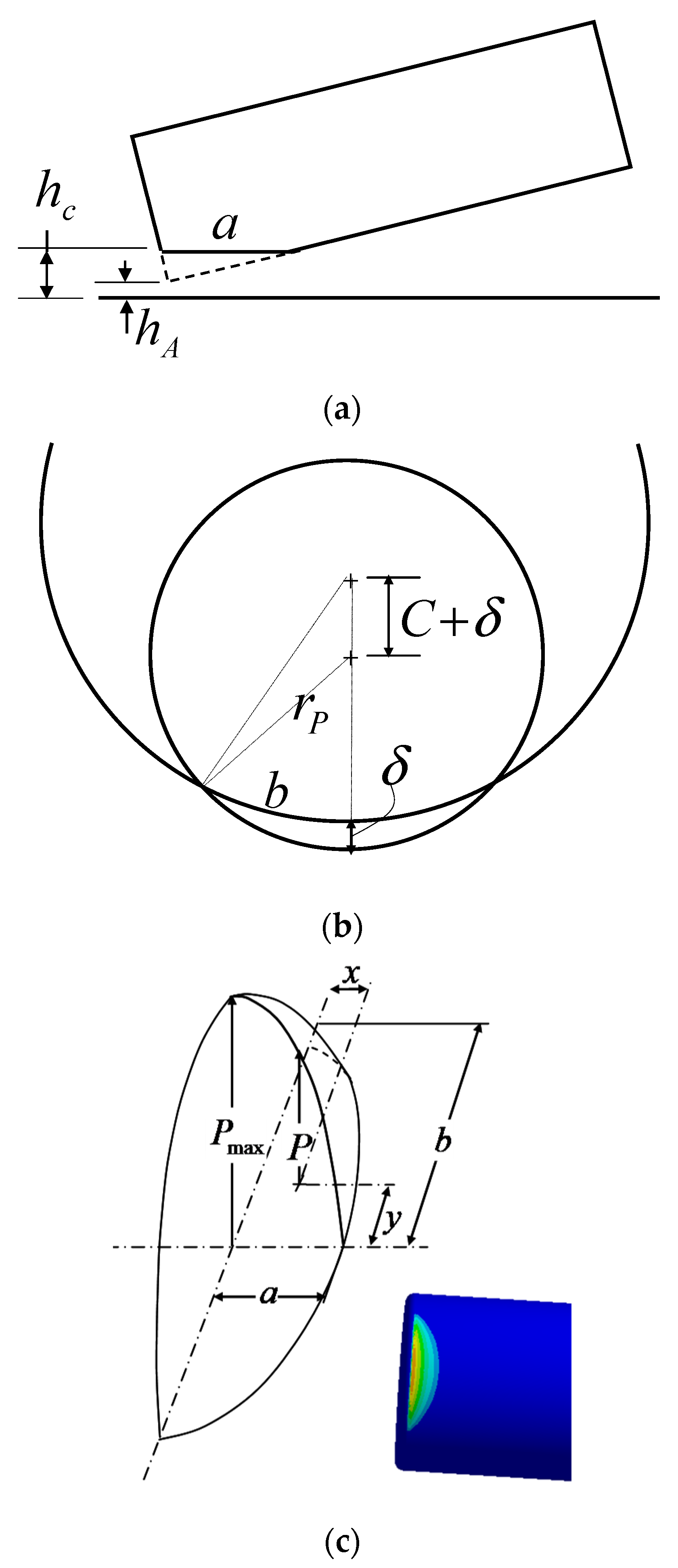
Here, the elastic boundary model assumed that the boundary lubrication patch shape was half of the hemisphere whose pressure distribution was also half of the Hertzian pressure distribution. Figure 3 depicts the boundary modeling scheme based on Hertz contact theory [23]. The main idea is that the contact patch between the inclined piston and cylinder, as shown in Figure 3a,b, is half of an elliptical Hertzian contact area, and its stress distribution could be as shown in Figure 3c. Figure 3c was obtained from a finite element linear elastic simulation of two solids. This assumption was considered by the authors’ intuition to be better than the assumption of rigid materials.
-
Boundary contact force and maximum contact stress:
W z = 2 E R π k e E 6 Φ 3 / 2 δ 3 / 2
P max = 3 W z π a b
The above notations were referenced from Ref. [23].
-
Frictional, leakage, and total power loss:
L ¯ f r i c = F ¯ f C P z v ¯ P
L ¯ l e a k = P ¯ C Q ¯ P C
L ¯ t o t = L ¯ f r i c + L ¯ l e a k

4. Numerical Results and Discussion

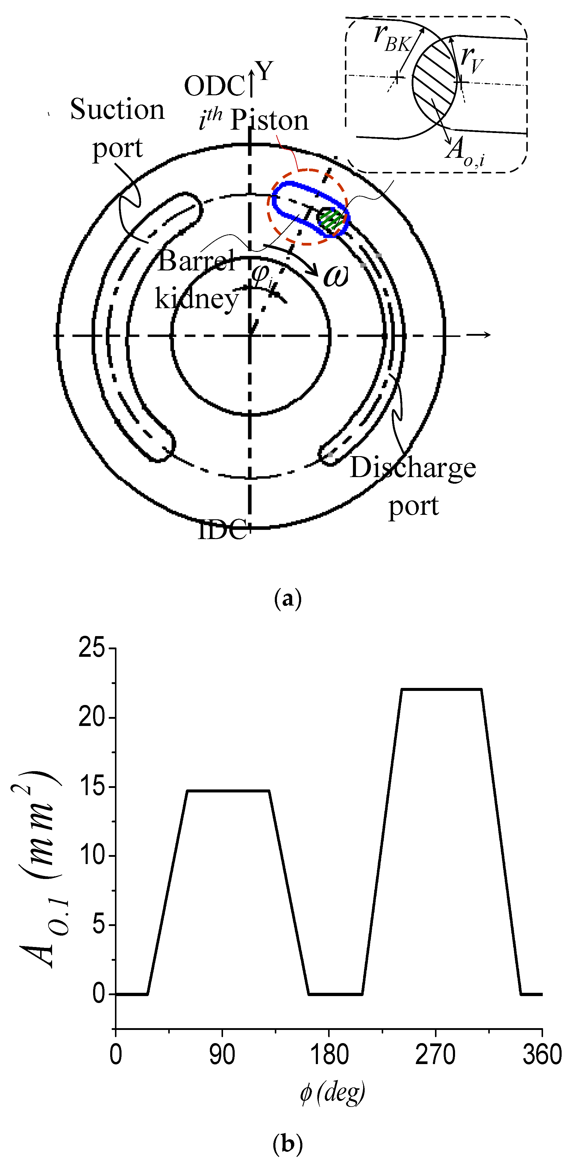
The specifications of the piston/cylinder part of the model machine are listed in Table 1. As for the valve opening holes, refer to Figure 4. Here, it was assumed that the number of portholes is just two for the high- and low-pressure parts, respectively.

4.1. Cylinder Chamber Pressure

From Equations (6)–(8), the chamber pressures of all cylinders could be calculated. Since the converged results of the cylinder pressures were found to be identical in all cylinder chambers, only the result of the first one is depicted in Figure 5.

4.2. Effect of Friction Coefficient

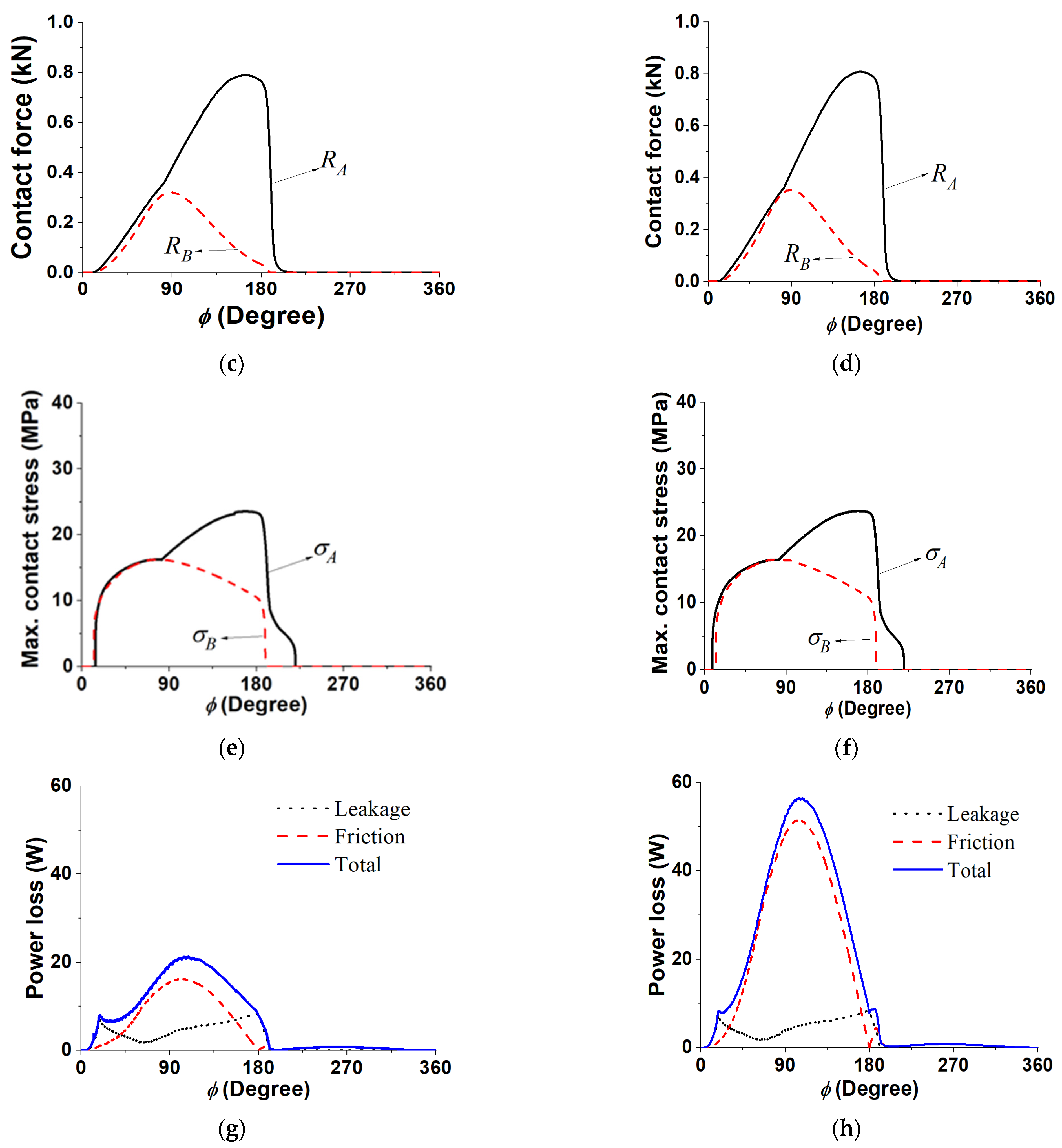
Figure 6 shows the comparative results according to the variation in the Coulomb friction coefficient. Even a fourfold change in the Coulomb friction coefficient did not lead to any change in the motion of the piston, the reaction force, or the leakage loss, with the simulation result of friction loss being the only variable showing a substantial change in response. The change in the friction loss comes from the fact that the resultant friction is composed of the boundary lubrication friction using the Coulomb friction coefficient and the viscous friction using the fluid viscosity. Therefore, the problem of determining this coefficient of friction should be considered to be important for achieving accurate predictions of pump power loss. The appropriate friction coefficient can be found through the experimental data. This study referred to the value of 0.02 used by Fang and Shirakashi [10] and Yamaguchi [17].

4.3. Effect of Piston/Cylinder Clearance

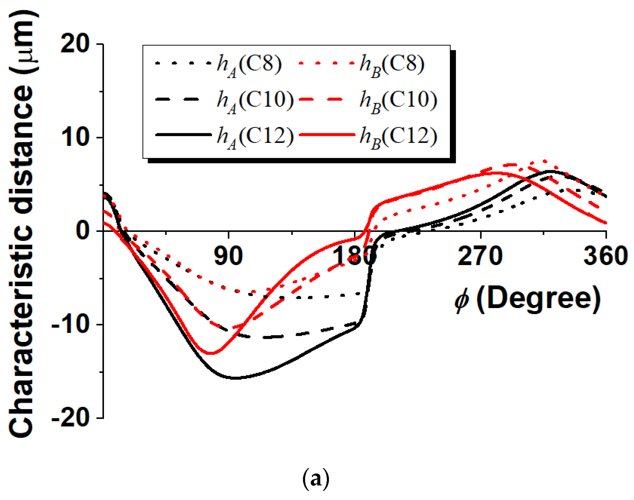
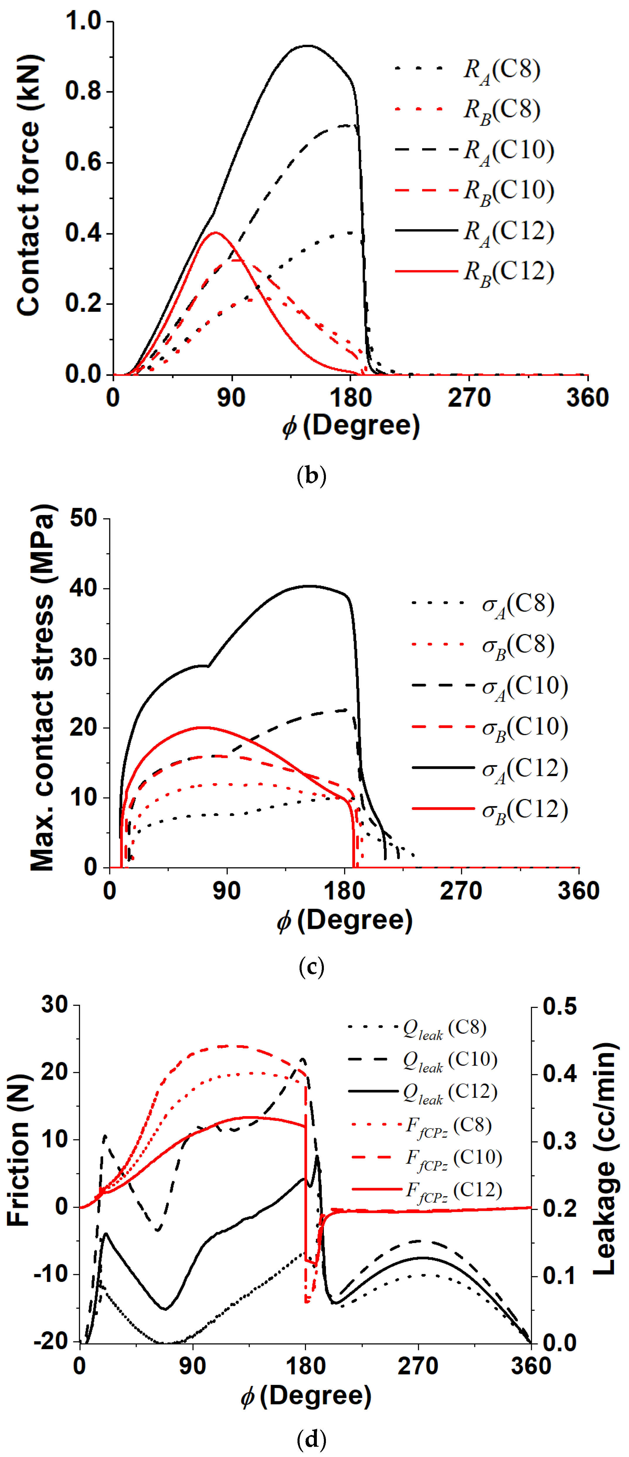
In the sliding part of the swash plate-type piston pump, the average clearance in the piston/cylinder part should be properly determined and machined. Since this clearance technique plays a key role in piston/cylinder lubrication, it was worth reviewing how much of this gap should be taken in this section. An optimal design strategy in the clearance requires the sum of frictional and leakage loss to be minimal [4]. However, it is important to keep in mind that this theory only holds when a full fluid lubrication regime is assumed. In this paper, since the pump was assumed to be subjected to severe conditions in which boundary lubrication could occur, a guide to this manufacturing clearance could be advised by examining how the loss changes in response to changes in the average clearance. Figure 7 shows the results of transient lubrication computer simulation for three kinds of clearance (8 μm, 10 μm, and 12 μm). First, the variation in the characteristic distance at locations A and B is shown in Figure 7a, where it can be seen that the characteristic distance becomes smaller as the average clearance increases. This means that the overall positional variation of the piston due to the elastic deformation becomes larger as the clearance increases. If the characteristic distance is large, the contact deformation is not necessarily large. This will become more apparent when the reaction force and the contact stress are considered together. Therefore, as can be seen in Figure 7b,c, the results of reaction force and maximum contact stress also show that the force and stress are larger at location A than they are at location B, and the larger the average clearance, the greater the reaction force and contact stress. In particular, the variation of the contact reaction force from 10 μm to 12 μm is not large compared to the variation from 8 μm to 10 μm, but the contact stress is relatively larger in the former case. It can be said that the larger the contact stress, the less durable the relative motion part is. Therefore, it can be concluded that the smaller the average clearance, the better the durability.
Figure 7e shows the leakage power loss, frictional power loss, and total power loss according to each average clearance. As can be seen in the figure, all power losses decrease as the average clearance decreases. Leakage losses can naturally be reduced by decreasing the clearance; however, from the perspective of viscous frictions, the smaller the average clearance, the greater the frictional force. That said, as discussed earlier in the discussion of the reaction force, in the situation where boundary friction occurs when passing over the discharge region, the total frictional loss will be governed by this boundary friction force rather than fluid friction. According to the friction model, the boundary friction force is proportional to the reaction force, so the friction loss will be further reduced in the case of a small average clearance with a lower reaction force.
In summary, in a swash plate-type piston pump with a reciprocating piston mechanism that receives strong lateral force, it could be concluded that making the average clearance small was good in terms of both durability and power loss. It was also known to be advantageous to perform the pump performance by machining and assembling the piston pump with a small average clearance in consideration of the problem of hydraulic clogging. However, since the problem of heat generation and machining accuracy due to viscous friction remains to be solved, it could be more accurate to say that the target should be a minimum clearance within both acceptable machining accuracy and allowable heat generation.

4.4. Effect of Piston Head Profiling

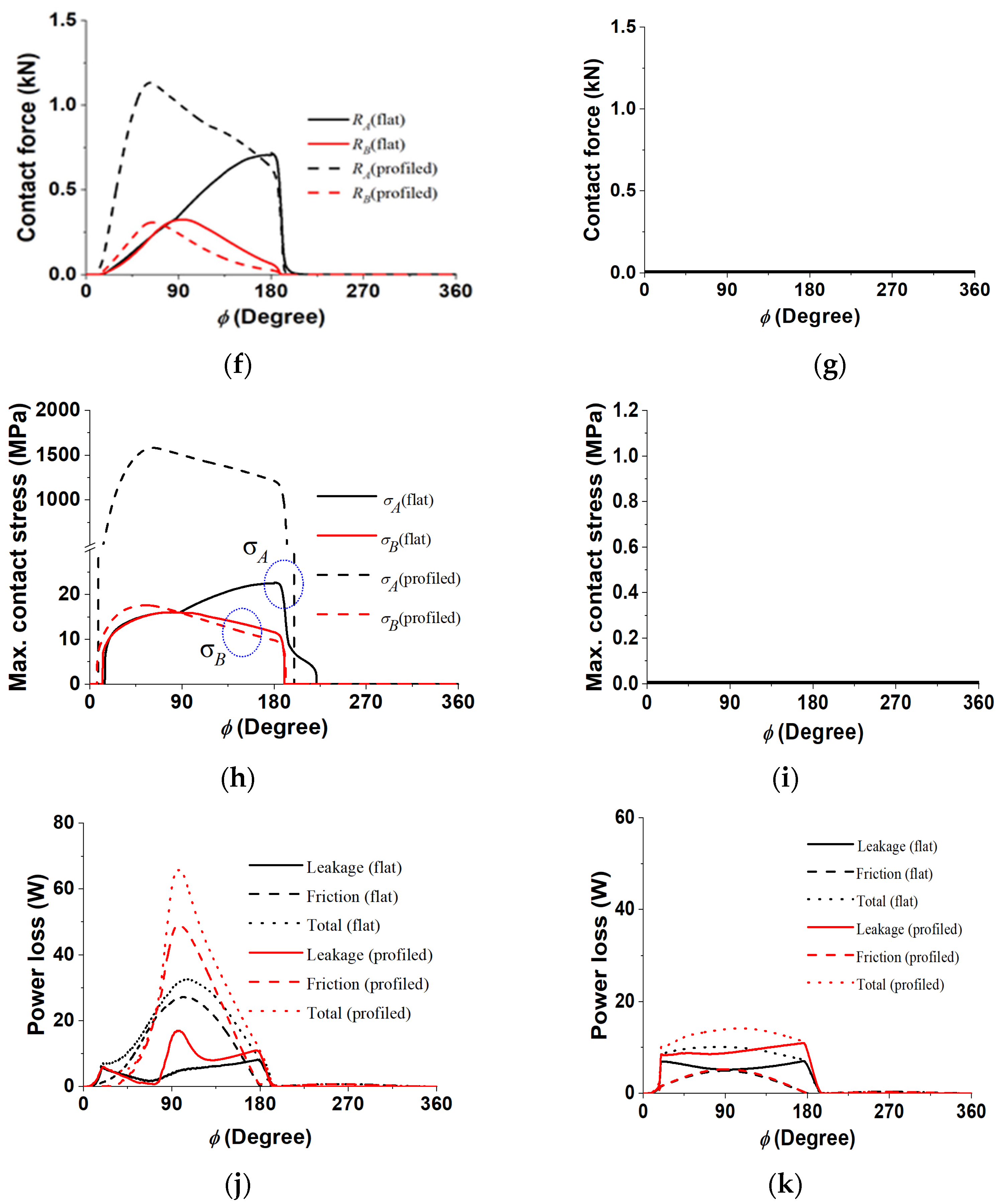
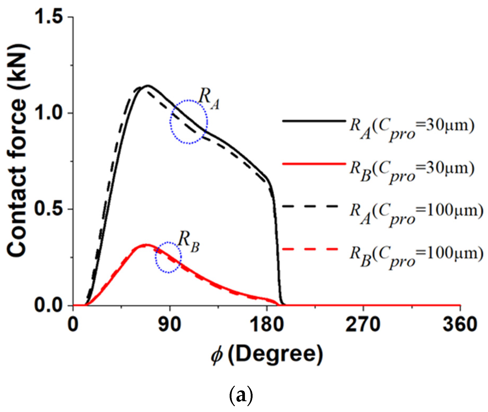
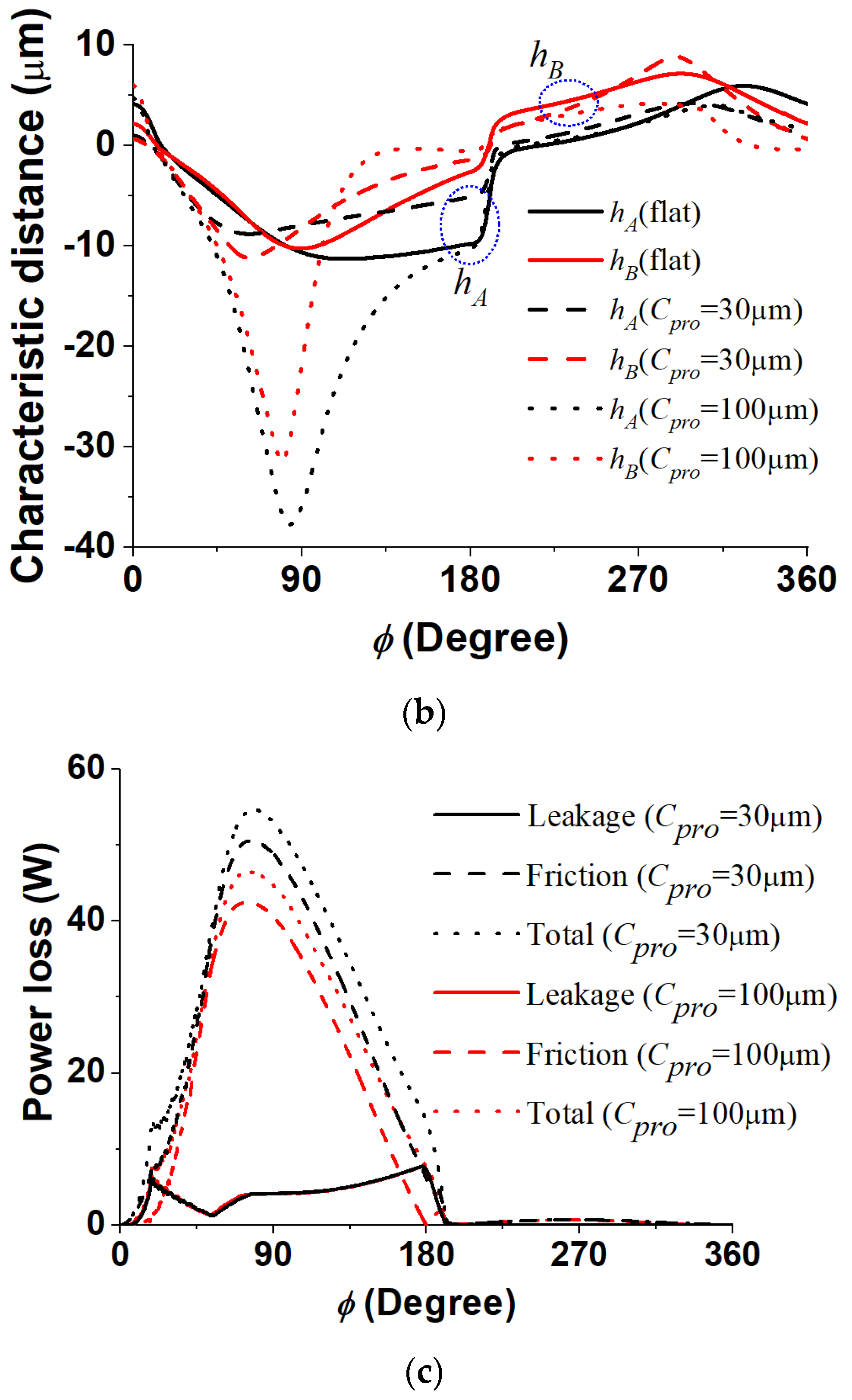
As mentioned in the introduction, many studies have examined the piston head profiling of piston pumps. In this paper, we also analyzed the case of profiling the head edges. The top of Figure 8 shows a perpendicularly angled piston and a profiled piston. The profiling was modeled as a quadratic polynomial function, and the width and height are l p r o and C p r o , respectively, with the respective dimensions of 2 mm and 0.1 mm. Assuming that profiling was a quadratic function and that the radius of the piston in the direction of the axis of symmetry of the piston was r 1 x among the radii of curvature of the Hertz contact ( r 1 x , r 1 y , r 2 x , r 2 y ), then r 1 x can be approximately expressed as r 1 x = l p r o 2 / 2 C p r o , and since the remaining radii of curvature ( r 1 y , r 2 x , r 2 y ) are given, then the reaction force can be obtained. The sum of the reaction forces in both the piston surface and profiling surface calculated by the elastic boundary model was used as the resultant reaction force at location A. All results of both the perpendicularly angled piston and the profiled piston are plotted on a graph, and the results are tabulated by two columns with swash angles of 17 degrees and 7 degrees, respectively.
A large swash angle means that the displacement volume of the pump is large. If the swash plate angle is large, the piston pump can achieve the performance needed to produce large power at a small volume. However, if the swash plate angle is large on the opposite side, then the piston receives more lateral force. It is currently a trend in swash plate pump design to select a large swash angle in the design stage, but this is then subject to the limitation described above. On the other hand, when the swash plate angle is 7 degrees, the displacement volume is small, but the lateral force acting on the piston is also small. In conclusion, the effect of profiling depends on the swash plate angle. Figure 8e,g,i show that full fluid lubrication occurs over the entire operating cycle, even without edge profiling at the swash plate angle of 7 degrees. Although Figure 8g,i are not blank, no boundary contact occurs at the swash plate angle of 7 degrees. When the edge profile was machined, the minimum film thickness per cycle also grew. Therefore, at least in terms of the minimum film thickness, it can be seen that edge profiling has a positive effect. However, in terms of power loss, the edge profiling side has a larger leakage loss, which is disadvantageous. In the case of the pump with the swash plate angle of 17 degrees, the piston was found to undergo boundary contact when passing through the high-pressure discharge part with or without edge profiling; further, with regard to the average during one cycle, the effect of the edge profiling is positive in terms of surface stress and negative in terms of power loss. These results are thought to be attributable to two factors. The first one is the difference in surface shape in the boundary contact area. The boundary contact radius is small in location A in the case of edge profiling, which will cause the magnitude of the reaction force and the concentration of surface stress to increase. Second, the piston tilt angle at which the profiled piston tilts to the boundary contact location is made larger, so the fluid film pressure difference between the upper and lower portions of the piston will become larger as well. In the present analysis, the length of the edge profiling was set to 2 mm, which accounted for a significant portion of the piston/cylinder sliding surface length of 12.9 mm. The ratio of the tilt angle at which the piston with the edge profiling can be tilted over the piston without edge profiling is equal to the ratio of the edge profiling length over the whole sliding surface length, so it can be tilted by a length ratio of 1.18 times (as 12.9 divided by 10.9 is equal to 1.18) with and without edge profiling. Therefore, the same applies whenever the swash plate angle is large or small or when there is profiling. As the same applies when discussing the average clearance, it can be concluded that it is still preferable to design the tilt angle to be small in a piston subjected to large lateral force. As a result, edge profiling is expected to have a more positive effect in the case of a pump with a small lateral force than a pump with a large lateral force. Figure 9 shows the calculation results in accordance with the size of edge profiling ( C p r o ). There was no significant change even when the edge profiling size was more than three times the size difference. The larger the edge profiling size, the smaller the amount of reaction force and surface stress, and the smaller the power loss.

4.5. Effect of Operating Condition

Piston pumps are characterized by their loss behavior, which is dependent on the operating speed and operating pressure. It is considered to be the case that the influence of the lubrication condition between the piston and the cylinder wall varies depending on the operating conditions. This section examines the effects of the operating conditions.
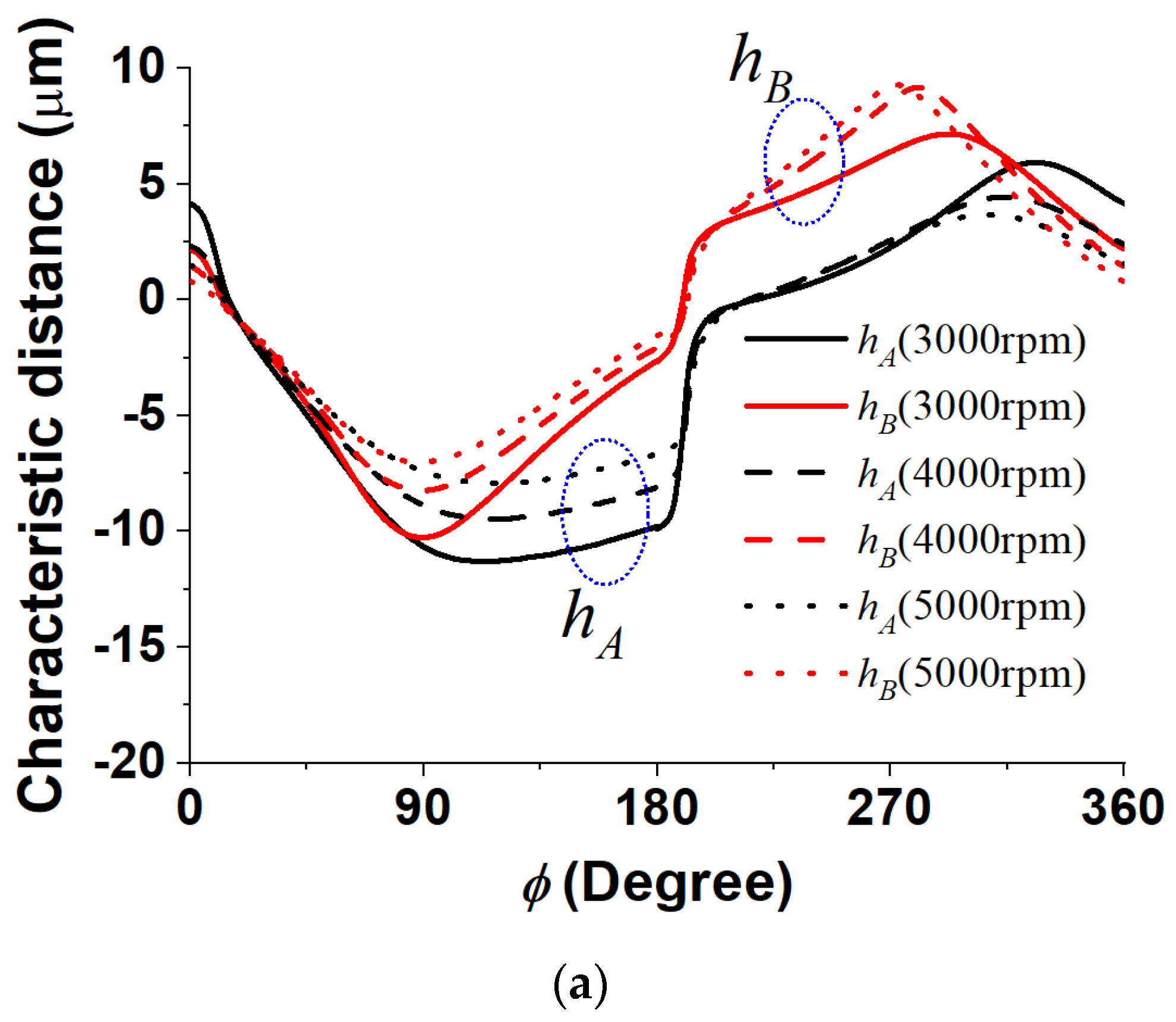
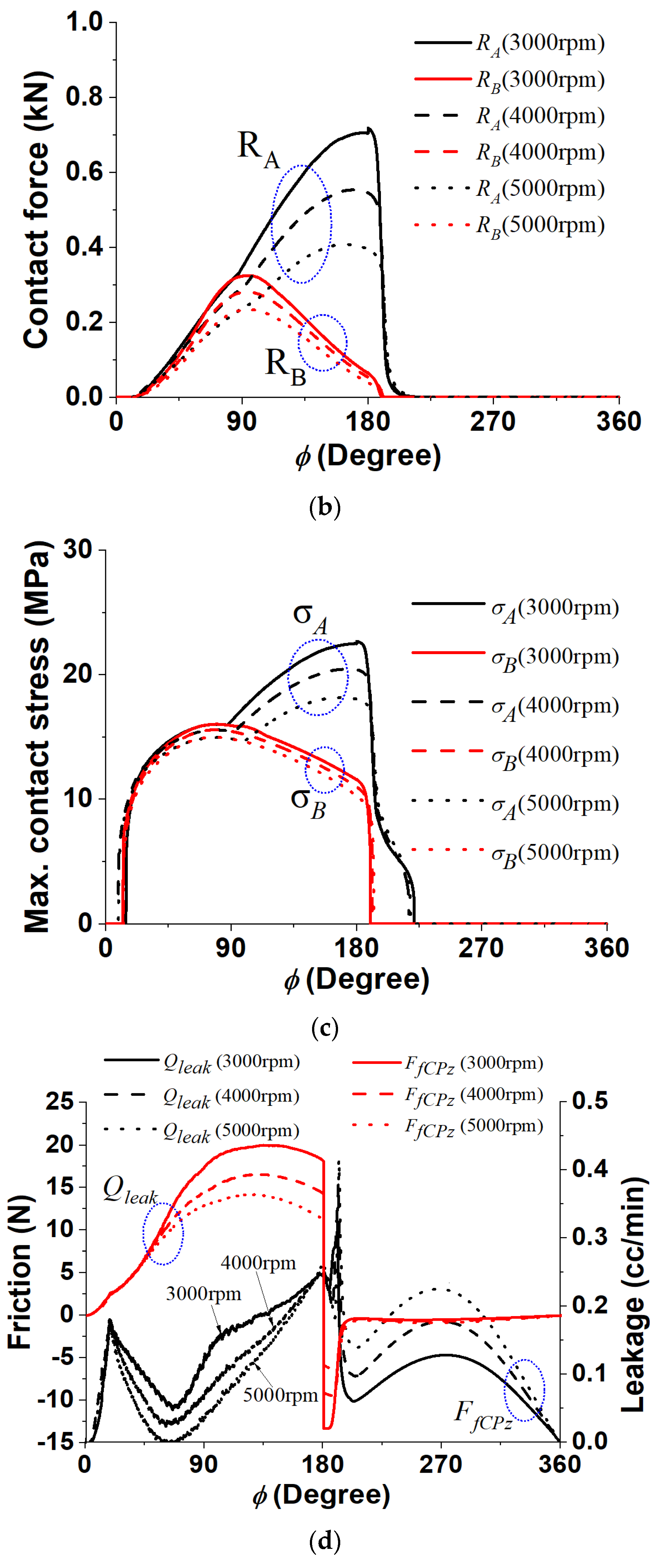
First, Figure 10 shows the micromotion and loss characteristics of the piston under varying operating speeds. As a result of analyzing three kinds of speed (3000 rpm, 4000 rpm, and 5000 rpm), the characteristic distances at A and B were found to decrease with increasing speed. This seems to be attributable to the increase in the bearing load with the increase in the fluid film pressure due to the wedge effect. Because this calculation excludes thermal analysis, the resultant difference may be smaller for each speed, considering the viscosity loss of the lubricating fluid as the speed increases. The reaction force and surface stress tend to decrease with increasing speed due to the increase in the bearing load with the increase in speed. Friction loss and leakage loss also tend to decrease with increasing operating speed. In the case of friction loss, the tendency can be easily grasped, because the reaction force described above becomes large when the reaction forces become large. In the case of leakage loss, the speed at which the piston moves in the direction of reducing the volume of the cylinder chamber in the discharge portion also increases with increasing rotating speed. Therefore, it will show a decrease in leakage rate due to the Couette traction of viscous fluid. This is likely to explain the calculation result showing that the leakage loss decreases as the rotating speed increases. In conclusion, the increase in the rotating speed reduces both the friction loss and the leakage loss, so the total power loss also decreases.
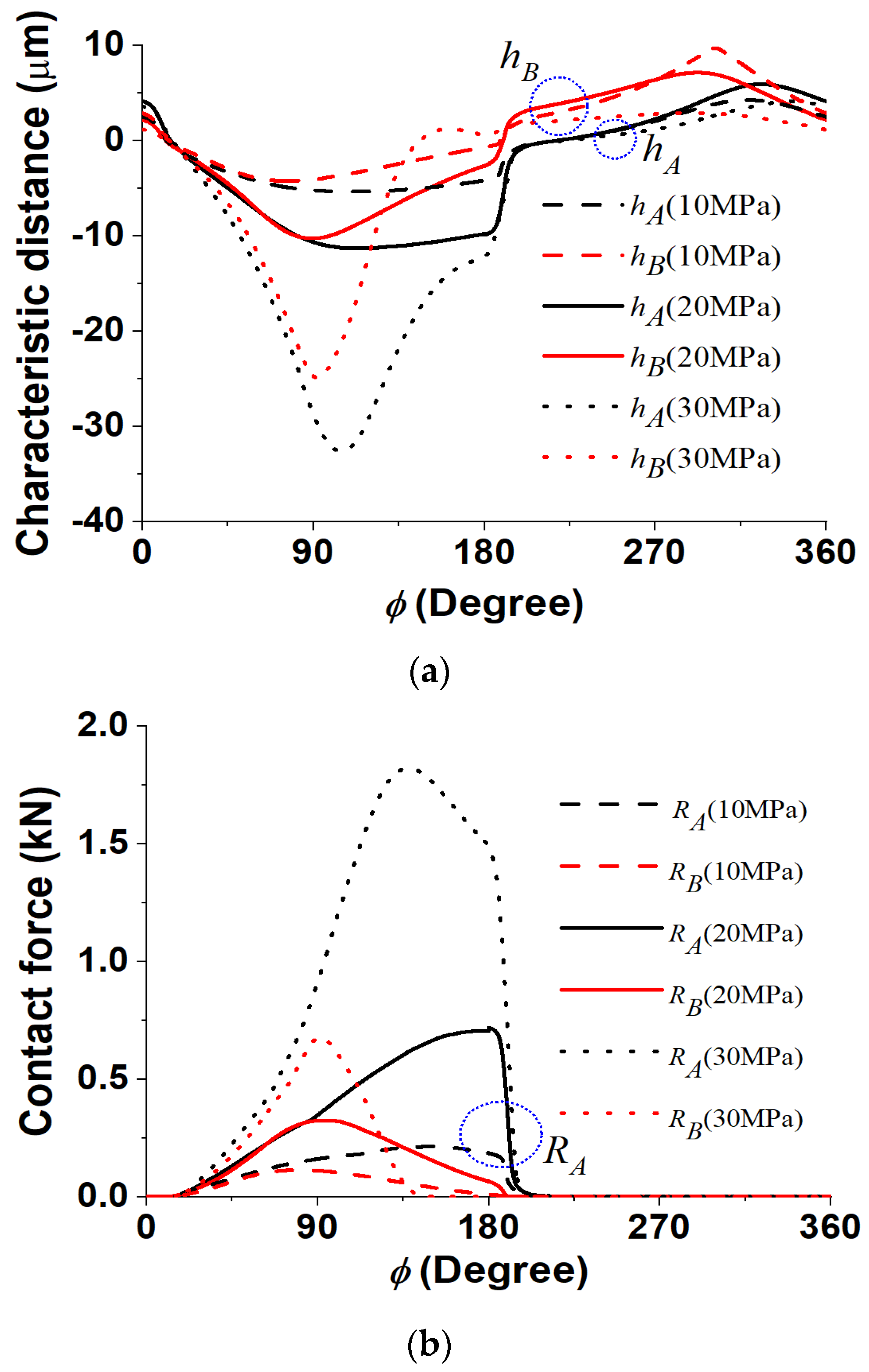
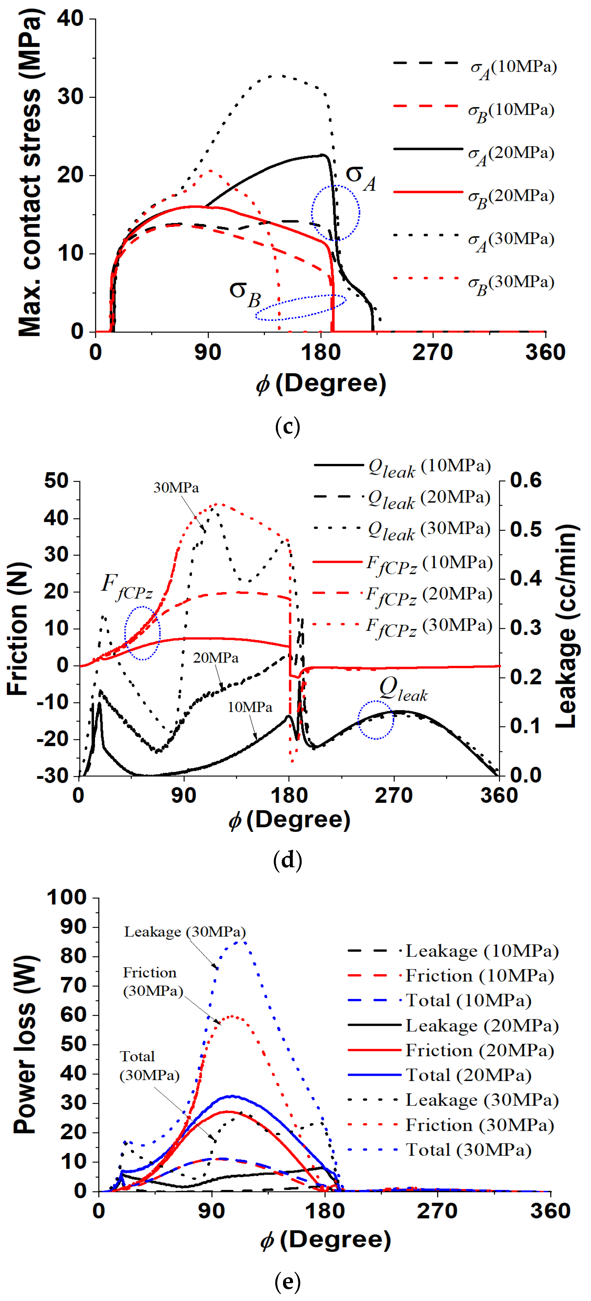
Figure 11 shows the calculation results of the lubrication characteristics based on the changes in operating pressure. An increase in operating pressure refers to an increase in the force exerted on the piston. Therefore, it was expected that such an increase would lead to a decrease in the characteristic distance along with increases in reaction force and surface stress. It should be noted that the increasing ratio of the reaction force or surface stress was increased much more with increasing pressure. In the case of the characteristic distance, it decreased by about 7 μm at maximum when the operating pressure increased from 10 MPa to 20 MPa, and then the characteristic distance decreased by 20 μm at 30 MPa. This nonlinear increase is believed to be due to the almost total loss of support from hydrodynamic lubrication. Although direct comparisons are difficult, the effect of pressure variations is greater than the effects of velocity calculated above. Although it was not considered in this paper, an increase in operating pressure will cause elastic deformation in the overall structure, which may lead to a more complicated impact. One more notable point in Figure 10 is that the boundary lubrication had already disappeared at location B before the discharge was completed at the operating pressure of 30 MPa. It is also believed that the contact condition at location B where the fluid film pressure was generated due to the wedge effect was changed due to the increase in the bearing load as a result of the increase in the operating pressure. Although the mechanism of pressure generation was different, this result was similar to the situation in which the bearing load increased near location B with increasing operating speed. In conclusion, the time integration of the friction loss and the leakage loss for one revolution increased with the increase in the operating pressure, and the degree increased as the operating pressure increased. Since actual pumps in practice often experience changes in their operating pressure, it would be helpful to keep this variation in lubricating characteristics in mind.

5. Conclusions

This research performed parametric studies using the previously formulated elastic boundary model of the piston/cylinder sliding mechanism and discussed the related design implications. The discussions herein are summarized as follows.
  • The friction coefficient of the boundary model did not affect the piston micromotions but it did affect the frictional power loss.
  • A larger clearance caused an increase in the piston tilt angle, which increased the boundary contact stress and power loss.
  • Piston head profiling can make the boundary reaction force decrease remarkably. In particular, it should be noted that, at a smaller swash plate angle, no contact occurred at all. However, large profiling length and height can cause the tilt angle to increase, which could have a negative effect on the contact stress and power loss.
  • The results showed that a higher operating speed has a positive effect on contact stress and a negative effect on power loss. Both effects can be well understood in the context of the full fluid lubrication theory, which states that velocity produces some dynamic bearing pressure. However, the authors believe that contact stress could increase if the piston mass were increased. This suggests that the obtained results could be reversed under different conditions. Furthermore, for a more in-depth future study, negative heat effects should be examined, as higher speeds will generate heat.
  • As for the operating pressure, it was considered to be the case that some critical pressure level exists where the contact stress and power loss both abruptly increase.
Future work will address other significant parameters such as various oil types, the effect of piston mass, coated materials, piston spin motion, and the existence of a piston ring, among other factors. Moreover, in terms of the computational aspect, the authors consider the simultaneous solving of all governing equations for the cylinder barrel, pistons, and slippers. In terms of physical modeling, future work should also consider fluid–structure thermal effects. Regarding commercialization, future work will explore the expected costs and the price of applying this technological procedure. In terms of product development, the authors will explore the application on different mechanisms or machines, such as engines, compressors, radial-type pumps, etc.

Author Contributions

Conceptualization, J.-H.S.; literature review and formal analysis, S.-H.H. and J.-H.S.; writing—original draft preparation, S.-H.H. and J.-H.S.; supervision, J.-H.S. All authors have read and agreed to the published version of the manuscript.

Funding

This research received no external funding.

Data Availability Statement

Data are contained within the article.

Acknowledgments

This work was supported by the Korea Hydro & Nuclear Power Co. (2023), “Regional Innovation Strategy (RIS)” through the National Research Foundation of Korea (NRF) funded by the Ministry Education (MOE) (No. 2022RIS-006), and the National Research Council of Science & Technology (NST) grant by the Korea government (MSIT) (No. CRC21011).

Conflicts of Interest

The authors declare no conflicts of interest.

Nomenclature

aBoundary contact length [m] (defined in Figure 3)
A Solid contact point at piston head
A ¯ O , i Overlaid area of ith cylinder and valve port
bBoundary contact width [m] (defined in Figure 3)
B Solid contact point at cylinder edge
C Average clearance [m]
CdOrifice flow coefficient = 0.65
CproHeight of the piston head profiling [m]
d ¯ C Cylinder bore diameter = d C / r P
d ¯ P Piston diameter = d P / r P
E Elastic modulus of solid [GPa]
E Effective modulus of elasticity in Hertzian theory [GPa] = 2 / 1 ν A 2 E A + 1 ν B 2 E B
F ¯ Force = F / 6 η ω r P / C 2 r P 2
h ¯ Fluid film thickness = h / C
h ¯ A , h ¯ B Characteristic distances (defined in Figure 3)
h ¯ c Critical film thickness (defined in Figure 3)
h ¯ min Minimum fluid film thickness
h B V , h P C , h S W Average clearances of leakage passages (=10 μm)
I ¯ a Axial moment of inertia (= I a ω / 6 η r P / C 3 r P 3 )
I ¯ t Transverse moment of inertia
K ¯ Fluid bulk modulus (= K / 6 η ω r P / C 2 )
lproLength of the piston head profiling [m]
L ¯ Power loss (= L / η ω 2 r P / C r P 3 )
L ¯ f r i c Frictional power loss
L ¯ l e a k Leakage power loss
L ¯ t o t Total power loss
l ¯ G , l ¯ P C , l ¯ P Piston dimensions shown in Figure 1b
m ¯ P Mass of piston (= m ω / 6 η r P / C 3 r P )
m ¯ P S Mass of piston/slipper assembly
M ¯ Moment acting on piston (= M / 6 η ω r P / C 2 r P 3 )
N P Number of pistons
O-X,Y, Z Reference coordinates
o-x, y, zLocal coordinates
P ¯ Fluid pressure (= P / 6 η ω r P / C 2 )
P ¯ C Cylinder chamber pressure
P ¯ C i ith cylinder chamber pressure
P ¯ d Discharge pressure
P ¯ h Housing pressure
P ¯ s Suction pressure
P ¯ V Valve port pressure
Q ¯ Volumetric leakage flow rate (= Q / ω r P 3 )
Q ¯ P C Leakage between piston and cylinder
Q ¯ S W Leakage between slipper and swash plate
Q ¯ V B Leakage between cylinder barrel and valve plate
R Inverse of curvature in Hertzian theory (= R x R y / R x + R y )
R ¯ Pitch circle radius (= R / r P )
R x Effective radius of curvature in x-plane in Hertzian theory [m]
R y Effective radius of curvature in y-plane in Hertzian theory [m]
R ¯ A , R ¯ B Boundary reaction forces in A and B (= R A / 6 η ω r P / C 2 r P 2 ,   R B / 6 η ω r P / C 2 r P 2 )
S Piston stroke [m]
z ¯ Axial coordinate of cylinder barrel surface (= z / r P )
t ¯ Time (= ω t )
V ¯ i Volume of the ith cylinder (= V i / R B o 3 )
V ¯ V Volume of the valve ports
α Inclined angle of swash plate
α r Radius ratio in Hertzian theory (= R y / R x )
δ ¯ Penetration depth in contact model (= δ / C ) (defined in Figure 3)
ε Eccentricity ratio of gravity center (= e / C )
ε x , ε y x- and y-component of eccentricity
k Ellipticity in Hertzian theory (= b / a )
η Absolute viscosity [Pa·s]
μ Coulomb friction coefficient of solid contact
ν Poisson ratio
θ ¯ Tilt angle (= θ r P / C )
θ ¯ x , θ ¯ y Tilt angles on X- and Y-axis
ϕCircumferential coordinate of piston
φ Shaft rotation angle [rad] (= t ¯ )
κ , χ Configuration angles [rad] (defined in Figure 1)
Ω ¯ x , Ω ¯ y Angular velocity of cylinder barrel on x- and y-axes (= ω x / ω , ω y / ω )
ω Shaft rotating velocity [rad/s]
ω P Piston spinning [rad/s] (= ω / 2 )
Ω ¯ P Characteristic rotating velocity (= 1 + ω P / ω )
ρ ¯ Fluid density (= ρ ω H 2 / 6 η )
  ¯ Nondimensional quantity

References

  1. Ernst, M.; Vacca, A. Hydrostatic vs. hydrodynamic components of fluid pressure in the tribological interfaces of axial piston machines. Trib. Int. 2021, 157, 106878. [Google Scholar] [CrossRef]
  2. Zhang, X.; Wu, H.; Chen, C.; Wang, D.; Li, S. Oil film lubrication state analysis of piston pair in piston pump based on coupling characteristics of the fluid thermal structure. Eng. Fail. Anal. 2022, 140, 106521. [Google Scholar] [CrossRef]
  3. Milojević, S.; Savić, S.; Marić, D.; Stopka, O.; Krstić, B.; Stojanović, B. Correlation between Emission and Combustion Characteristics with the Compression Ratio and Fuel Injection Timing in Tribologically Optimized Diesel Engine. Teh. Vjesn. 2022, 29, 1210–1219. [Google Scholar] [CrossRef]
  4. Ivantysyn, J.; Ivantysynova, M. Hydrostatic Pumps and Motors: Principles, Design, Performance, Modeling, Analysis, Control and Testing; Tech Books International: New Delhi, India, 2003; pp. 81–98. [Google Scholar]
  5. Hong, Y.S.; Lee, S.R.; Kim, J.H.; Lee, S.Y. Application of a DLC-Coating for improving hydrostatic piston shoe bearing performance under mixed friction conditions. Int. J. Precis. 2015, 16, 335–341. [Google Scholar] [CrossRef]
  6. Yamaguchi, A. Motion of Pistons in Piston-Type Hydraulic Machines: 3. Exponential Function-Type Piston. Bull. JSME 1977, 19, 413–419. [Google Scholar] [CrossRef]
  7. Park, T.J.; Lee, C.O. Effect of Piston Shape on the Lubrication Characteristics of Hydraulic Piston Pump and Motor. J. KSTLE 1994, 10, 47–53. [Google Scholar]
  8. Lasaar, R.; Ivantysynova, M. An Investigation into Micro- and Macrogeometric Design of Piston/Cylinder Assembly of Swash Plate Machines. Int. J. Fluid Power 2004, 5, 23–37. [Google Scholar] [CrossRef]
  9. Kumar, S.; Bergada, J.M. The effect of piston grooves performance in an axial piston pumps via CFD analysis. Int. J. Mech. Sci. 2013, 66, 168–179. [Google Scholar] [CrossRef]
  10. Fang, Y.; Shirakashi, M. Mixed Lubrication Characteristics Between the Piston and Cylinder in Hydraulic Piston Pump-Motor. J. Tribol. 1995, 117, 80–85. [Google Scholar] [CrossRef]
  11. Pelosi, M.; Ivantysynova, M. A novel fluid-structure interaction model for lubricating gaps of piston machines. Fluid Struct. Interact. V 2009, 105, 13–24. [Google Scholar] [CrossRef]
  12. Malazi, M.T.; Aksoy, M.H.; Okbaz, A. An investigation on fluid-structure interaction of two tandem rectangular cylinders. Appl. Eng. Lett. 2023, 8, 158–166. [Google Scholar] [CrossRef]
  13. Xie, Z.; Song, P.; Hao, L.; Shen, N.; Zhu, W.; Liu, H.; Shi, J.; Wang, Y.; Tian, W. Investigation on effects of fluid-structure-interaction (FSI) on the lubrication performances of water lubricated bearing in primary circuit loop system of nuclear power plant. Ann. Nucl. Energy 2020, 141, 107355. [Google Scholar] [CrossRef]
  14. Jin, X.; Xia, P.; Liu, Z.; Ma, W.; Zhang, P.; Liang, Y. Thermo-hybrid lubrication FSI-CFD model for the static characteristics of hybrid porous tilting pad bearings. Tribol. Int. 2022, 167, 107397. [Google Scholar] [CrossRef]
  15. Xie, Z.; Jiao, J.; Wrona, S. The fluid-structure interaction lubrication performances of a novel bearing: Experimental and numerical study. Tribol. Int. 2023, 179, 108151. [Google Scholar] [CrossRef]
  16. Daryani, R.; Ersan, E.C.; Celebi, M.S. Impact of multi-grade localized calcifications on aortic valve dynamics under helical inflow: A comparative hemodynamic study. Appl. Sci. 2023, 13, 12983. [Google Scholar] [CrossRef]
  17. Yamaguchi, A. Motion of the Piston in Piston Pumps and Motors: The Case of Metallic Contact. Int. J. JSME III 1990, 33, 627–633. [Google Scholar] [CrossRef]
  18. Manring, N.D. Friction forces within the cylinder bores of swash-plate type axial-piston pumps and motors. J. Dyn. Syst. Meas. Control 1999, 121, 531–537. [Google Scholar] [CrossRef]
  19. Lyu, F.; Zhang, J.; Sun, G.; Xu, B.; Pan, M.; Huang, X.; Xu, H. Research on wear prediction of piston/cylinder pair in axial piston pumps. Wear 2020, 456, 203338. [Google Scholar] [CrossRef]
  20. Zhang, J.; Lyu, F.; Xu, B.; Huang, W.; Wu, W.; Guo, Z.; Xu, H.; Huang, X. Simulation and experimental investigation on low wear rate surface contour of piston/cylinder pair in an axial piston pump. Trib. Int. 2021, 162, 107127. [Google Scholar] [CrossRef]
  21. Zhang, J.; Qiu, X.; Gong, X.; Kong, X. Wear behavior of friction pairs of different materials for ultra-high-pressure axial piston pump. Proc. Inst. Mech. Eng. E J. Process. Mech. Eng. 2019, 233, 945–953. [Google Scholar] [CrossRef]
  22. Shin, J.H.; Cho, K.W. A simplified calculation model for the sliding contact boundaries in a hydrostatic piston mechanism. J. Eng. Math. 2018, 113, 143–163. [Google Scholar] [CrossRef]
  23. Hamrock, B.J.; Brewe, D.E. Simplified Solution for Stresses and Deformations. J. Lubr. Technol. 1983, 105, 171–177. [Google Scholar] [CrossRef]
  24. Richardson, D.; Sadeghi, F.; Rateick, R.G.; Rowan, S. Experimental and analytical investigation of floating valve plate motion in an axial piston pump. Tribol. Trans. 2017, 60, 537–547. [Google Scholar] [CrossRef]
  25. Richardson, D.; Sadeghi, F.; Rateick, R.G.; Rowan, S. Dynamic modeling of floating valve plate motion in an axial piston pump. Tribol. Trans. 2018, 61, 683–693. [Google Scholar] [CrossRef]
  26. Guo, J.; Randall, R.B.; Borghesani, P.; Smith, W.A.; Haneef, M.D.; Peng, Z. A study on the effects of piston secondary motion in conjunction with clearance joints. Mech. Mach. Theory 2020, 149, 103824. [Google Scholar] [CrossRef]
  27. Fritz, B.; Scheichl, B. Comprehensive multi-scale cylinder lubrication model for reciprocating piston compressors: From rig-id-body dynamics to lubricant-flow simulation. Tribol. Int. 2023, 178, 108028. [Google Scholar] [CrossRef]
  28. Guo, Y.; Tang, Y.; Wang, L.; Diao, A.; Peng, X. Optimal design of the piston trajectory for the ionic liquid compressor applied in hydrogen stroge. Int. J. Hydrogen Energy 2024, 56, 709–716. [Google Scholar] [CrossRef]
  29. Li, Z.; Xu, S.; Gong, G.; Bi, Y.; Xu, L.; Zhang, L.; Ren, Z. Study of friction characteristics of slipper pair of large displacement high-pressure piston pump. Lubricants 2022, 10, 363. [Google Scholar] [CrossRef]
  30. Shin, J.H. Computational study on dynamic pressure in a swash-plate axial piston pump connected to a hydraulic line with an end resistance. J. Mech. Sci. Technol. 2015, 29, 2381–2389. [Google Scholar] [CrossRef]
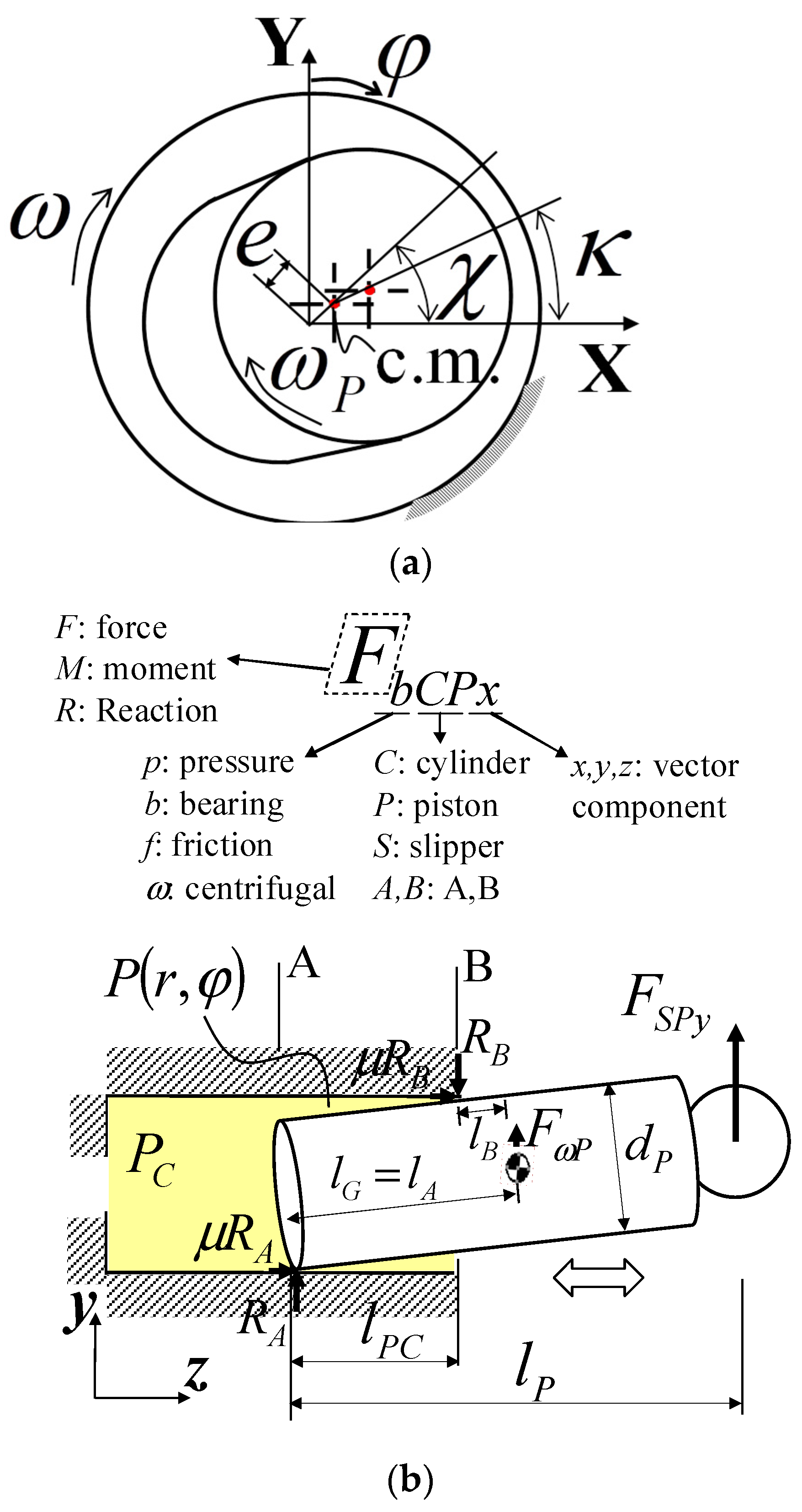
Figure 1. Concerned piston/cylinder mechanism with lateral force: (a) axial view; (b) lateral view.
Lubricants 12 00055 g001
Figure 2. Swash plate-type piston pump: (a) lateral section view; (b) axial view of valve portholes.
Lubricants 12 00055 g002aLubricants 12 00055 g002b
Figure 3. Definitions of boundary model parameters: (a) lateral view; (b) axial view; (c) modeling boundary contact with Hertz theory.
Lubricants 12 00055 g003
Figure 4. Valve opening area: (a) axial view of valve port; (b) opening area variation with shaft rotating angle.
Lubricants 12 00055 g004
Figure 5. Cylinder chamber pressure.
Lubricants 12 00055 g005
Figure 6. Effect of Coulomb friction coefficient: (a) motion parameters at μ = 0.01; (b) motion parameters at μ = 0.04; (c) contact force at μ = 0.01; (d) contact force at μ = 0.04; (e) maximum contact stress at μ = 0.01; (f) maximum contact stress at μ = 0.04; (g) power loss at μ = 0.01; (h) power loss at μ = 0.04.
Lubricants 12 00055 g006aLubricants 12 00055 g006b
Figure 7. Effect of the piston/cylinder clearance: (a) characteristic distance; (b) contact force; (c) maximum contact stress; (d) friction and leakage; (e) power loss.
Lubricants 12 00055 g007aLubricants 12 00055 g007bLubricants 12 00055 g007c
Figure 8. Effect of head profiling in accordance with swash pate angles: (a) two inclined angles of swash plate; (b) motion parameters at α = 17°; (c) motion parameters at α = 7°; (d) characteristic distance at α = 17°; (e) characteristic distance at α = 7°; (f) contact force at α = 17°; (g) contact force at α = 7°; (h) maximum contact stress at α = 17°; (i) maximum contact stress at α = 7°; (j) power loss at α = 17°; (k) power loss at α = 7°.
Lubricants 12 00055 g008aLubricants 12 00055 g008b
Figure 9. Effect of head profiling height: (a) contact force; (b) characteristic distance; (c) power loss.
Lubricants 12 00055 g009aLubricants 12 00055 g009b
Figure 10. Effect of operating velocity: (a) characteristic distance; (b) contact force; (c) maximum contact stress; (d) friction and leakage; (e) power loss.
Lubricants 12 00055 g010aLubricants 12 00055 g010bLubricants 12 00055 g010c
Figure 11. Effect of operating pressure: (a) characteristic distance; (b) contact force; (c) maximum contact stress; (d) friction and leakage; (e) power loss.
Lubricants 12 00055 g011aLubricants 12 00055 g011b
Table 1. Model pump specifications.
Design Parameters and Boundary ConditionsValues
Volumetric displacement (cc/rev)4.8
The number of pistons NP (number)9
Piston diameter rP (mm)4.18
Pitch circle radius R (mm)15.35
Swash plate angle α (degree)17
Dimension lC, lG, lP, lg0 (mm)24.6, 15.2, 29.0, 2.30
Port volumes VV (mm2)3.35 (discharge), 38.5 (suction)
Valve port width rV (mm)0.9 (discharge), 1.2 (suction)
Carry-over angles of valve port φV (degree)32.6/18.6/32.6/18.6
Barrel kidney width rBK (mm)1.6
Dead volume at IDC (mm3)685.5
Barrel surface design lB1, lB2 (mm)2.25, 2.4
Slipper surface design rS1>, rS2 (mm)3.0, 5.1
Mass of piston/slipper assembly mPS (g)12
Mass of piston mP (g)9.5 (aluminum alloy)
Moment inertia Ia, It (kg·m2)1.03 × 10⁻⁶, 7.69 × 10⁻⁶
Suction pressure Ps (MPa)0.3
Housing pressure Ph (MPa)0.1
Mostly used discharge pressure Pd (MPa)20
Mostly used speed ω (rpm)3000
Fluid type: Mineral oil
- dynamic viscosity (Pa∙s)0.0705
- density (kg/m3)870
Disclaimer/Publisher’s Note: The statements, opinions and data contained in all publications are solely those of the individual author(s) and contributor(s) and not of MDPI and/or the editor(s). MDPI and/or the editor(s) disclaim responsibility for any injury to people or property resulting from any ideas, methods, instructions or products referred to in the content.