Article

Transient Simulation Analysis of Needle Roller Bearing in Oil Jet Lubrication and Planetary Gearbox Lubrication Conditions Based on Computational Fluid Dynamics

1
College of Mechanical and Electrical Engineering, Nanjing University of Aeronautics and Astronautics, Nanjing 210016, China
2
National Key Laboratory of Helicopter Aeromechanics, Nanjing University of Aeronautics and Astronautics, Nanjing 210016, China
3
Science and Technology on Helicopter Transmission Laboratory, Zhuzhou 412000, China
*
Author to whom correspondence should be addressed.
Lubricants 2024, 12(2), 39; https://doi.org/10.3390/lubricants12020039
Submission received: 20 October 2023 / Revised: 23 January 2024 / Accepted: 26 January 2024 / Published: 29 January 2024

Abstract

:
The transient lubrication conditions of rolling bearings are different in gearboxes and bearing testers. It has been observed that samples of qualified rolling bearings tested in rolling bearing testers often fail and do not meet lifespan requirements when employed in other lubrication conditions. This may be caused by different factors affecting the bearing in testing and applying lubrication. Needle roller bearings were selected for this study to investigate the causes of this phenomenon in terms of lubrication. Based on the computational fluid dynamics (CFD) method, fluid domain models for the same type of rolling bearings with different lubrication conditions were established. The transient flow fields of rolling bearings with oil jet lubrication in a tester and splash lubrication in a planetary gearbox were simulated. The air–oil transient distribution of rolling bearings in two kinds of lubrication was analyzed. The results indicate that the rotational speed significantly affected the oil jet lubrication of the needle roller bearing. The average oil volume fraction rose by 0.2 with the increase in the bearing speed from 1200 r/min to 6000 r/min and by 0.06 with the increase in the oil jet velocity from 8 m/s to 16 m/s. The splash lubrication of the bearings in the planetary gearbox was directly related to the immersion depth of the rolling bearings in the initial position. Meanwhile, the splash lubrication of the bearings was also affected by other factors, including the initial layout of the planetary gears. The increase in speed from 1200 r/min to 6000 r/min made the average oil volume fraction of splash lubrication decrease by 4.4%. The average oil volume fraction of the bearings with splash lubrication was better than that with oil jet lubrication by an average of 41.9% when the bearing speed was in the low-speed stage, ranging from 1200 r/min to 3600 r/min. On the contrary, the bearings with oil jet lubrication were better than those with splash lubrication by an average of 31.8% when the bearing speed was in the high-speed stage, ranging from 4800 r/min to 6000 r/min.

1. Introduction

Rolling bearing is one of the indispensable components in a transmission system. Due to space and location constraints, needle roller bearings are commonly used in compact transmission systems such as planetary gearboxes because of their capacity to withstand high rotational speeds and heavy shock loads, in addition to being lightweight and highly rigid. Under normal operating conditions, the bearings in a planetary gearbox do not have oil jet lubrication devices. Therefore, the rolling bearings and gears are lubricated with churning oil [1,2,3]. Oil jet lubrication, which has the advantages of reducing lubricant consumption, easy control, and excellent lubrication effects, is used to lubricate high-speed bearings. The lubricant oil is directly injected into the rolling bearing through a small-diameter nozzle. However, the mechanism of oil jet lubrication is complex. The diagram of the principle of an oil jet lubrication system is shown in Figure 1.
During the design and research phase, rolling bearings are tested using bearing testers with oil jet lubrication [4,5]. While the performance of rolling bearings can be evaluated, noticeable differences exist between oil jet lubrication and splash lubrication. Practical engineering cases show that these differences may result in bearings losing efficacy in operating lubrication conditions. This appears to be closely connected to the two types of lubrication. In recent years, researchers have conducted a lot of numerical simulation studies [6,7,8] on the oil jet lubrication of rolling bearings and the splash lubrication of gearboxes to investigate the phenomena based on computational fluid dynamics (CFD) [9,10].
In the area of rolling bearings with oil injection lubrication, Liu Hongbin et al. [11,12] investigated the penetration mechanism and atomization of oil injection lubrication for high-speed rolling bearings using a numerical–experimental method. The effects of different rotational speeds and injection speeds on the percentage of oil with large particle sizes in the bearing cavity were researched. Zheng et al. [13] experimentally analyzed the effects of oil injection lubrication parameters, such as the ejection angle and the diameter of the ejection hole. The results showed that the oil jet parameters significantly affect the cooling and lubrication of high-speed rolling bearings. The fluid domain model of a ball bearing was established by Zhang et al. [14] based on CFD. The flow field in the bearing cavity at different operating speeds and jet velocities was numerically calculated and researched. The results indicated that the oil volume fraction in the ball bearing cavity decreases when the rolling bearing speed or jet velocity increases. Liu et al. [15] developed a fluid–structure coupling numerical model of an oil-jet-lubricated cylindrical roller bearing in a high-power gearbox, in which the slip mesh model and volume of fluid (VOF) method were used. Heat sources defined as the transient thermal boundary were imposed on the rollers. The experiment validated the simulation results. It indicated that the oil flow rate, speed, waviness amplitude, oil viscosity, and nozzle number significantly influence the lubricating characteristics of rolling bearings. A multiphase numerical simulation and the corresponding tests were conducted to investigate the stratified air–oil flow inside jet cooling ball bearings by Wu et al. [16,17,18]. It was discovered that the oil distribution of the volume fraction affects the temperature distribution of rolling bearings. A higher temperature always appears in the lower oil volume fraction region.
When it comes to the splash lubrication of rolling bearings in gearboxes, the literature is sparse. However, other simulations of gearboxes are also informative. Moshammer et al. [19] simulated the splash lubrication of a gearbox and verified it via experiments, which showed that the simulation method can describe the flow field. Concli et al. [20] applied the innovative mesh handling technique to planetary gears to study the internal lubrication and the related power dissipations based on CFD simulations without geometrical simplifications. However, the lubrication of rolling bearings was ignored. Höhn et al. [21] experimentally investigated the effect of the oil immersion depth on the temperature rise in gears. They found that the temperature rises faster when the gearbox is immersed in a lower depth of oil and that the churning power loss incurred at higher depths of oil immersion is higher. Mastrone et al. [22] applied a new meshing strategy to the numerical analysis of a planetary gearbox based on CFD. The simulation results were compared with the experiment by using a transparent housing cover. In the study, for the first time, experimental observations and CFD simulation were successfully combined to evaluate the numerical approach used to predict oil distribution and contribute to a better understanding of oil flow in planetary gears. Liu et al. [23] developed a highly detailed CFD model of a splash-lubricated planetary test gearbox of an FZG internal gear test rig. It predicted the lubricant distribution in the planetary gearbox. Nevertheless, the issue of distributing cylindrical roller bearings did not raise any significant concern.
In summary, the studies mentioned above concentrated on the oil jet lubrication of rolling bearings or the splash lubrication of gearboxes, investigating the oil jet parameters, oil immersion depths, and rotational speeds, and giving relevant conclusions and laws. However, the lubrication of rolling bearings in gearboxes has rarely been studied. Comparative analyses of rolling bearings with oil jet lubrication and in gearboxes with splash lubrication are also relatively sparse.
In this paper, needle roller bearings commonly used in planetary gearboxes were selected for this study to investigate the air–oil transient distribution of rolling bearings with oil jet lubrication and in a gearbox with splash lubrication. The CFD models of the lubricant prediction for two types of lubrication were established based on the dynamic mesh model and SST k-ω turbulence model, using FLUENT 2021R1 software for its good stability and high accuracy. The effects of different rotational speeds, oil jet velocities, and oil filling levels on the lubricant distribution characteristics of the rolling bearings for the two types of lubrication were analyzed.
At present, there are few full models including rolling bearing simulations of gearbox lubrication. A bearing design using oil jet lubrication cannot completely meet the requirements for gearbox transmission. In this paper, a full gearbox splash lubrication model was compared with oil jet lubrication for the first time. Based on the above reasons, the advantages of CFD visualization were utilized to perform lubrication simulations of the gearbox. Furthermore, the mentioned phenomenon, wherein qualified rolling bearings that are tested in bearing testers using oil jet lubrication often fail when used with other lubrications, was explained by comparing the simulation results of the rolling bearings with the two types of lubrication. This study contributes to helping researchers understand the distinctions between rolling bearings with two types of lubrication and guiding the design of bearings and the prediction of service life.

2. Materials and Methods

2.1. CFD Numerical Calculation Model

2.1.1. Governing Equations

This study focused on the transient flow field of rolling bearings. It is necessary to establish the governing equations of a fluid to simulate the turbulent motion of the fluid in different operating conditions. Without considering the influence of the temperature, it is assumed that the flow field consists of only two incompatible and incompressible media: oil and air. The continuity equation is:
u x + v y + w z = 0
where u, v, and w are the velocity vectors; x, y, and z represent directions. The momentum equation is:
ρ u i t + x j ρ u i u j = p x i + τ i j x j + ρ g i + F i
where p is the static pressure; τ i j is the stress tensor; and g i and F i are the gravitational volume force and external volume force in the i-direction, respectively. F i includes other model-related source terms, such as porous media and custom source terms. The stress tensor is expressed as:
τ i j = μ u i x j + u j x i 2 3 μ u l x l δ i j

2.1.2. SST k-ω Turbulence Model

The SST k-ω turbulence model takes the transport of turbulent shear stresses in turbulent viscosity into account and adds an eddy viscosity limiter to solve the problem of eddy viscosity overestimation. At present, the research on fluid flow belongs to turbulence. In the fully developed flow region, the model switches to the k-ε formulation to avoid being too sensitive to the inlet-free incoming flow. As a result, the SST k-ω turbulence model was selected. The equations are as follows:
( ρ k ) t + ( ρ k u i ) x i = x i μ + μ t σ k k x i + G k Y k + S k + G b
( ρ ω ) t + ( ρ ω u i ) x i = x i μ + μ t σ ω ω x i + G ω Y ω + D ω + S ω + G ω b
where k denotes the turbulent kinetic energy; ω represents the specific dissipation rate; ρ is the fluid density; G k represents the generation of turbulent kinetic energy due to the mean velocity gradients; G ω represents the generation of ω; Y k and Y ω represent the dissipation of k and ω due to turbulence; S k and S ω are user-defined source terms; and G b and G ω b indicate the effect of buoyancy on turbulence.

2.1.3. Multiphase Model

This study needed to analyze the oil–gas two-phase model. The air and oil around rolling bearings and gears form a complex flow field under the influence of rotation. To represent the interface between the lubricant and the air, the volume of fluid (VOF) [24] model was adopted to trace the phase interface between the two incompatible fluids. The VOF model simulates the flow of two or more fluids that cannot mix by calculating the volume fraction of phases in a grid cell. For one of the phases q, the volume fraction equation within the control cell is:
ρ q α q t + ρ q v q ( α q ) = S α q
where ρ q is the density of phase q; v q is the velocity of phase q; S α q is the source term; and α q is the volume fraction of phase q. Since the studies of the rolling bearings in two types of lubrication only had two phases, the equation can be simplified to obtain the following conclusions.
α a i r + α o i l = 1
where α a i r is the volume fraction of the air phase; α o i l is the volume fraction of the oil phase.
Based on the above equation, it can be concluded that when α a i r = 0, the control unit is full of oil; when α a i r = 1, the control unit is filled with air; and when 0 < α a i r < 1, an oil–air interface is contained in the control unit. The solution of the continuity equation of the volume fraction allows us to trace the oil–air interface.

2.1.4. Dynamic Mesh Model

Since the dynamic mesh technique can fulfill the mesh motion more realistically in the transient calculation, it was used to simulate the rigid boundary motion of rollers, inner and outer rings, and gears. The methods of smoothing and re-meshing were used to update the volume mesh in the deforming regions. The default parameters were selected for the spring smoothing method. Furthermore, the maximum cell skewness was set to 0.7 for the re-meshing method. The reason for this setting was that when the mesh skewness exceeds 0.7, it can better reconstruct areas with poor mesh quality. The re-meshing method was used to agglomerate cells that violated the skewness or size criteria and re-mesh these cells or faces. The mesh quality of local reconstruction was guaranteed to avoid negative volume. The smoothing method is suitable for small deformations while keeping the number of nodes unchanged. The basic idea of this method is to consider the nodes as ideal springs to each other and update the node positions by calculating the spring force balance.
F i = j n i k i j ( Δ x j Δ x i )
where n i is the number of neighboring nodes connected to node i; k i j is the spring constant between node i and j, and Δ x i are Δ x j the displacements of node i and its neighbor j.
k i j = k c x i x j
where k c is the value for the spring constant factor. The value range is 0~1, where the larger the value, the wider the range of influence.

2.2. Computational Domains and Meshing

2.2.1. Computational Domains

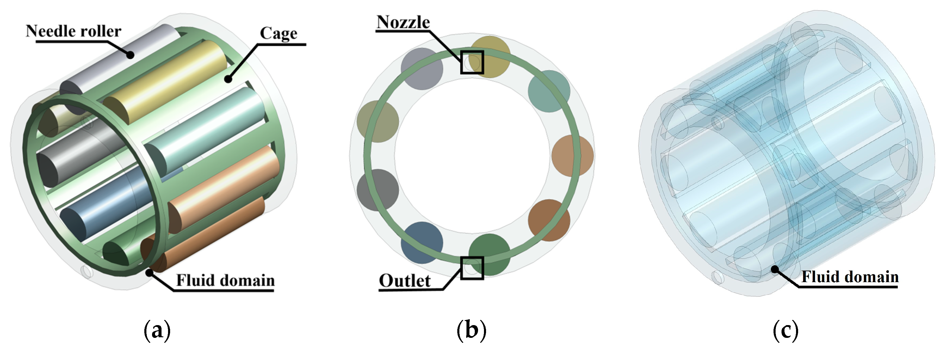
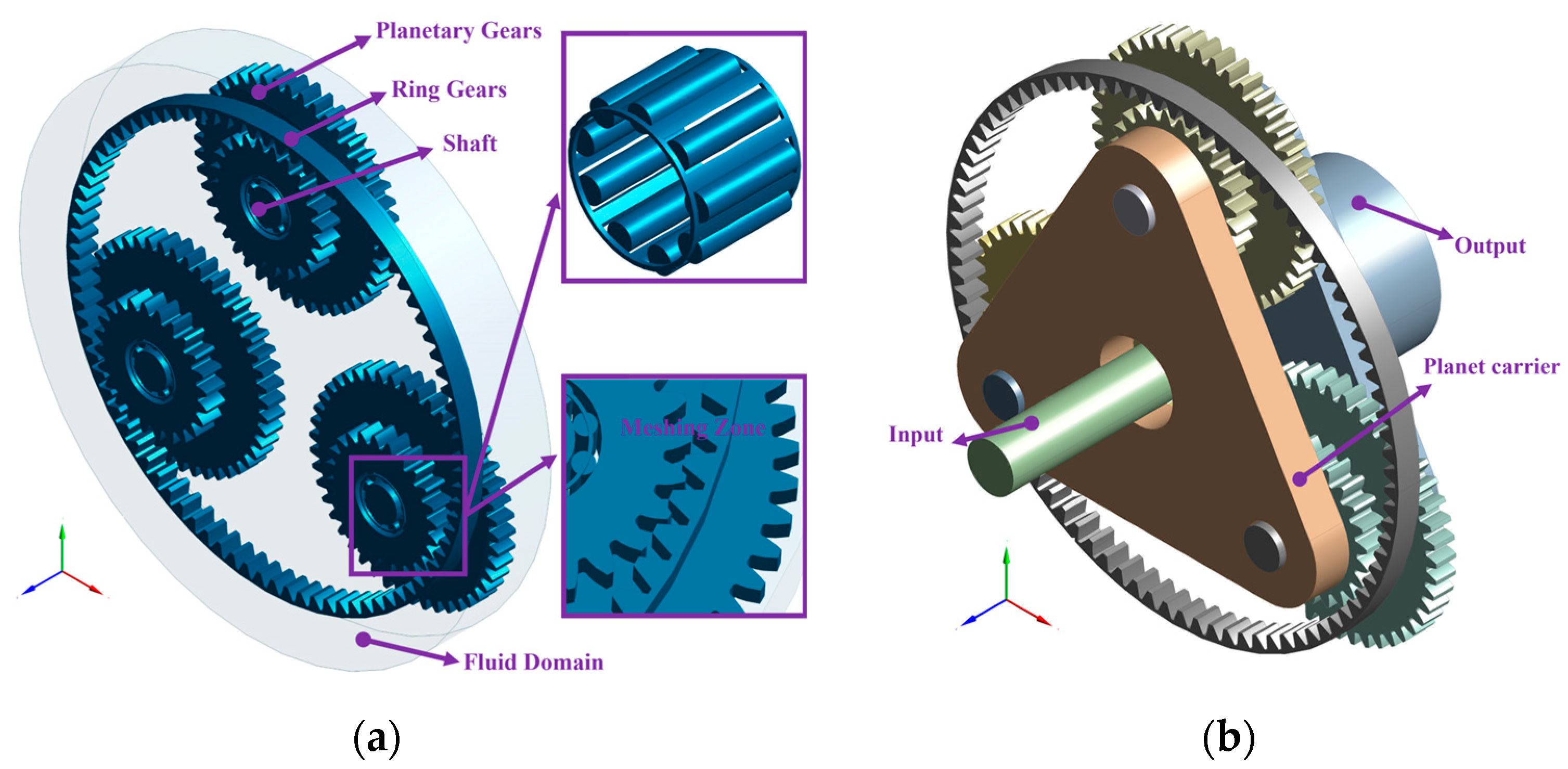
The computational domains of the two kinds of lubrication were obtained via Boolean operation after building the needle roller bearing (HKH1214-RS) and the planetary gearbox in the modeling software, as shown in Figure 2 and Figure 3. Moreover, the primary model of the planetary gearbox before simplification is shown in Figure 3b. The structural parameters of the needle roller bearing and the gears in the planetary gearbox are shown in Table 1 and Table 2. The clearance between the needle rollers and the inner and outer raceways has an important effect on the meshing and the subsequent solution results, so it was kept at an appropriate value in the fluid domain of the rolling bearing. Given that it is extremely difficult to mesh the narrow backlash of the zone in the fluid domain of the planetary gearbox, it was necessary to widen the backlash of the meshing zone appropriately [25]. The unimportant features were removed and appropriately simplified.

2.2.2. Meshing of Computational Domains

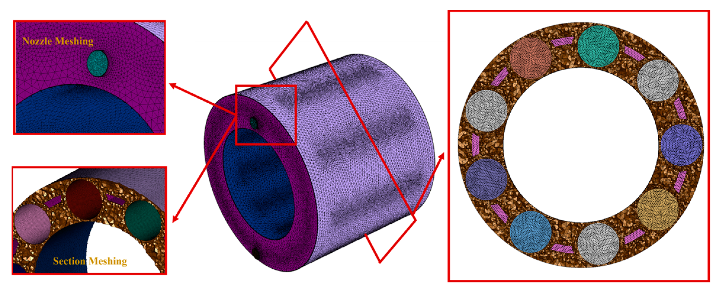
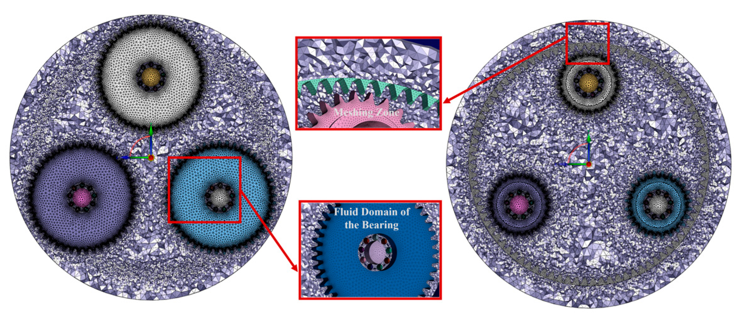
An unstructured tetrahedral mesh was used to generate the computational domains of the needle roller bearing in the planetary gearbox with splash lubrication and the needle roller bearing with oil jet lubrication. Considering the calculation accuracy and the amount of calculation, the grid cells of the nozzles, the clearances between the needle rollers and raceways in the computational domain of the needle roller bearing, and the narrow backlash of the gear meshing zone in the computational domain of the planetary gearbox were refined. The capture curvature and capture proximity were set to ‘Yes’, setting the curvature normal angle and num. of cells across the gap to 16° and 3, respectively. These settings could refine mesh cells in the specified area based on the defined curvature and narrow gap. The average element qualities of the computational domain for the needle rolling bearing and the planetary gearbox were 0.81 and 0.85, respectively. The number of cells in the entire fluid domains of the needle roller bearing with oil injection lubrication and in the planetary gearbox with splash lubrication was approximately 0.7 million and 6.5 million. The meshes of the two computational domains are shown in Figure 4 and Figure 5.

2.2.3. Boundary Conditions and Simulation Parameter Settings

The upper nozzle was set as the velocity inlet, while the lower nozzle was set as the pressure outlet in the fluid domain of the needle roller bearing with oil jet lubrication. The setting of the oil filling level was realized via the patch function in the initialization. Other boundary condition settings including the rotation of the cage, the autorotation of the needle rollers in the bearing computational domain, and the autorotation of the planetary gears in the planetary gearbox computational domain were described with compiled user-defined function (UDF) files. The formula for the rotational speed and the formula for the autorotational speed of the rollers are as follows:
n m = n 2 ( 1 + D w cos α d m )
n R = d m n 2 D w 1 ( D w cos α d m ) 2
where n m is the rotational speed of the cage; n R is the autorotational speed of the needle rollers; D w is the diameter of the needle roller; ρ q is the diameter of the bearing pitch circle; and α is the contact angle.
The influence of gravity was considered, and the value was set as 9.81 m/s2. To ensure calculation convergence and accuracy, the SIMPLE algorithm for the coupled pressure–velocity solution was adopted, and the pressure term discretization was in PRESTO format. Meanwhile, the relaxation factor was appropriately reduced to ensure the stability of the calculation. The time step was also set at a suitable value of 2 × 10⁻⁶. The oil–gas two-phase flow field and distribution in the computational domain were realized by setting up the multiphase model. The fluid materials of the two computational domains were air and oil. The physical properties of the density and viscosity of the air were 1.225 kg/m3 and 1.7894 × 10⁻⁵ kg/(m·s). The mineral oil FVA4 with a viscosity grade of ISO VG460 [26] was used as the lubricant for the computational domains. The main properties of the lubricant are listed in Table 3. All simulations of the two computational domains were carried out at an oil sump temperature of 40 °C.

3. Results and Discussion

This research focused on the air–oil transient distribution of needle roller bearings with oil jet lubrication and in a planetary gearbox with splash lubrication. The rotational speeds and the oil jet velocities of the needle roller bearings with oil jet lubrication were investigated for the transient oil distribution. Meanwhile, the rotational speeds and oil filling levels of the needle roller bearing in the planetary gearbox with splash lubrication were analyzed. The simulation results of the bearing with the two types of lubrication are compared herein.

3.1. Simulation Results and Discussion of Oil Jet Lubrication

The quantity of oil to be injected into the fluid domain can be determined according to d m n [27]. The nozzle diameter in the oil jet lubrication was set as 0.8 mm. When the influence of the oil jet velocities, which varied from 8 m/s to 16 m/s with a gradient of 2 m/s, was considered for the transient oil distribution, the rotational speed at 1200 r/min was used as the constant. When the influence of the rotational speeds, which varied from 1200 to 6000 r/min with a gradient of 1200 r/min, was considered, the jet velocity at 12 m/s was used as the constant. The operating conditions of the needle roller bearing with oil jet lubrication are summarized in Table 4.
The lubricant entered from the end face into the fluid domain. This led to an uneven distribution of oil in the axis direction. Two cross-sections were selected as references to analyze the lubrication of the rollers on the axis. The positions of the two cross-sections (Z = 0.001 mm; Z = 0.004 mm) in the fluid domain are shown in Figure 6.
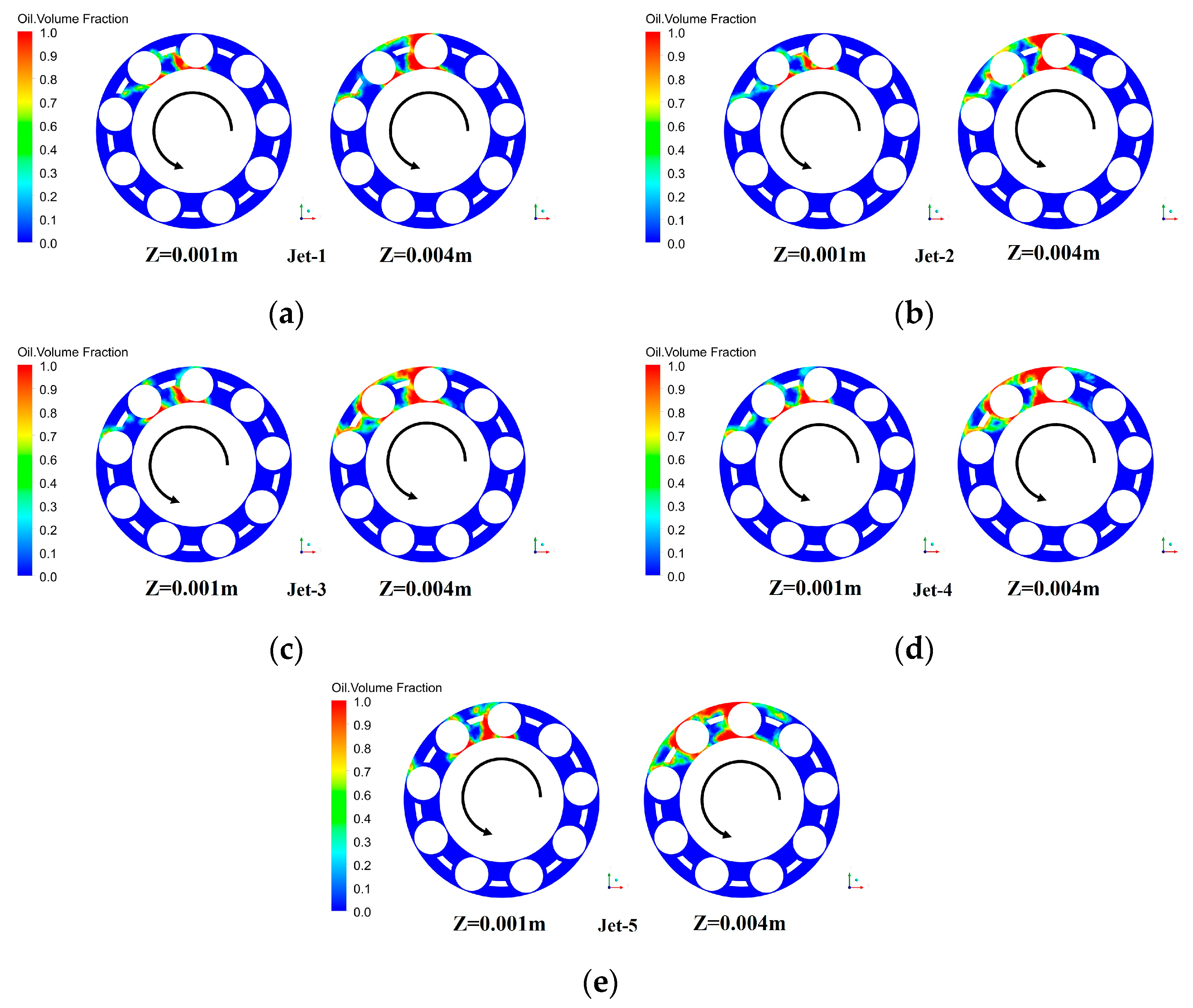
Figure 7 demonstrates the air–oil transient distributions for the needle roller bearing at different injection speeds when the rotational speed was constant. As shown in the pictures, the lubricant entered from the injector nozzle and began to accumulate near the vicinity of the injector nozzle. Subsequently, it gradually spread out and dispersed in the fluid domain as the needle rollers and cage rotated. Finally, the lubricant spread further into the fluid domain to the contact areas via the autorotation of the needle rollers. It can be seen that the more lubricant there was in the fluid domain of the bearing, the more noticeable the lubricant was on the needle roller surfaces with the increase in the oil jet velocity compared with the state of the oil distribution in the fluid domain at the same moment. However, the lubricant was distributed more and unevenly on both sides of the bearing. On the one hand, this was because the lubricant injected from the nozzle took a long time to spread out in time at the low rotational speed. On the other hand, this was due to the shading of the rollers and cage end surfaces, which caused a large amount of oil to accumulate near the injection nozzle. The large amount of lubricant on the opposite side of the nozzle was the result of the increase in the oil jet velocity. Although the rise in the oil jet velocity improved the lubrication to some extent, the effect was not apparent for a little oil on the roller surfaces.
Figure 8 shows the air-oil transient distributions at the different oil jet velocities and the same moment for cross-section Z = 0.001 m and cross-section Z = 0.004 m, where the positions of the two cross-sections in the fluid domain are shown in Figure 6. Cross-section Z = 0.004 m was closer to the injector, and cross-section Z = 0.001 m was further away. It is evident that the closer the cross-section was to the nozzle, the more oil it contained. From the nozzle in the negative direction of the Z-axis, the oil distribution of the cross-section gradually decreased. Furthermore, the oil volume fraction in the two cross-sections slowly increased when the jet velocity increased.
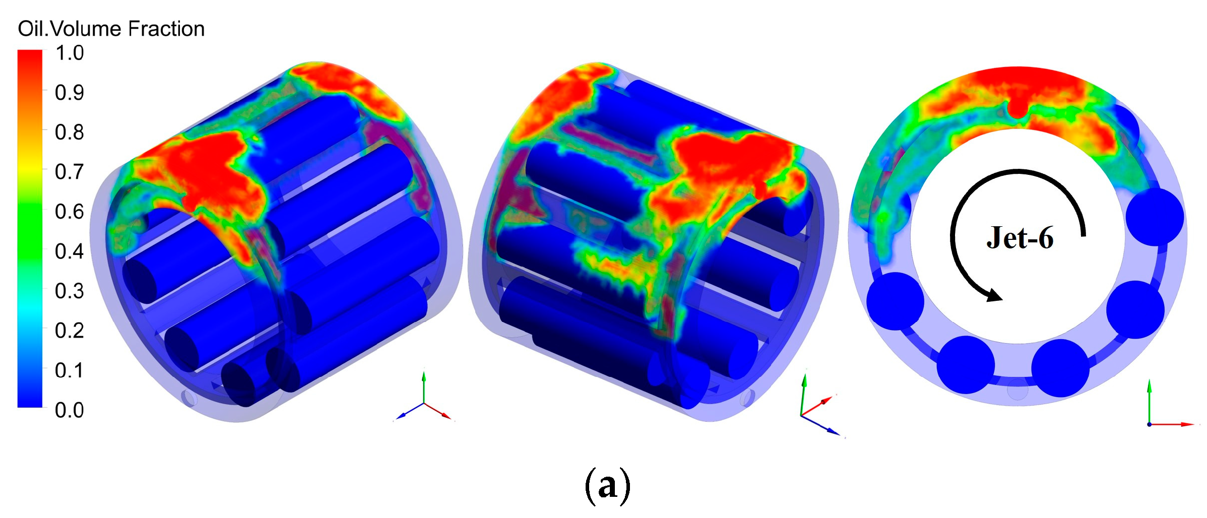
The air-oil transient distributions in the bearing with oil jet lubrication at different speeds are shown in Figure 9. The jet velocity was approximately 14 m/s. It can be observed that both the end faces were filled with oil while the bearing was at a lower speed. When the speed increased to 2400 r/min, the needle rollers were exposed to the air, and microbubbles were mixed into the oil around the outer ring. At a high speed, such as 4800 r/min or 6000 r/min, much more oil was thrown into the outer ring with the increase in the centrifugal force. Furthermore, the oil thrown into the outer ring was dragged to the inner ring via the autorotation of the rollers. In the high-speed stage, the air-oil distribution inside the bearing tended to be uniform. From the view of the end face, most of the oil that gathered near the nozzle began to disperse in the rotation direction of the bearing as the speed gradually reached 6000 r/min.
The oil volume fraction contours in cross-section Z = 0.001 m and cross-section Z = 0.004 m with different speeds are shown in Figure 10. It can be seen that the oil lubricated very few needle rollers in the low-speed stage and highly gathered around the end face. The amount of oil in cross-section Z = 0.004 m was more than in cross-section Z = 0.001 m because Z = 0.004 m was closer to the nozzle. As the bearing speed continued to increase, it can be found that the oil phase occupied a smaller region around both the inner ring and the outer ring. With the air constantly mixed into the lubricant, the oil-air two-phase flow field closely surrounded the roller surfaces. More oil entered the contact areas of the rollers.
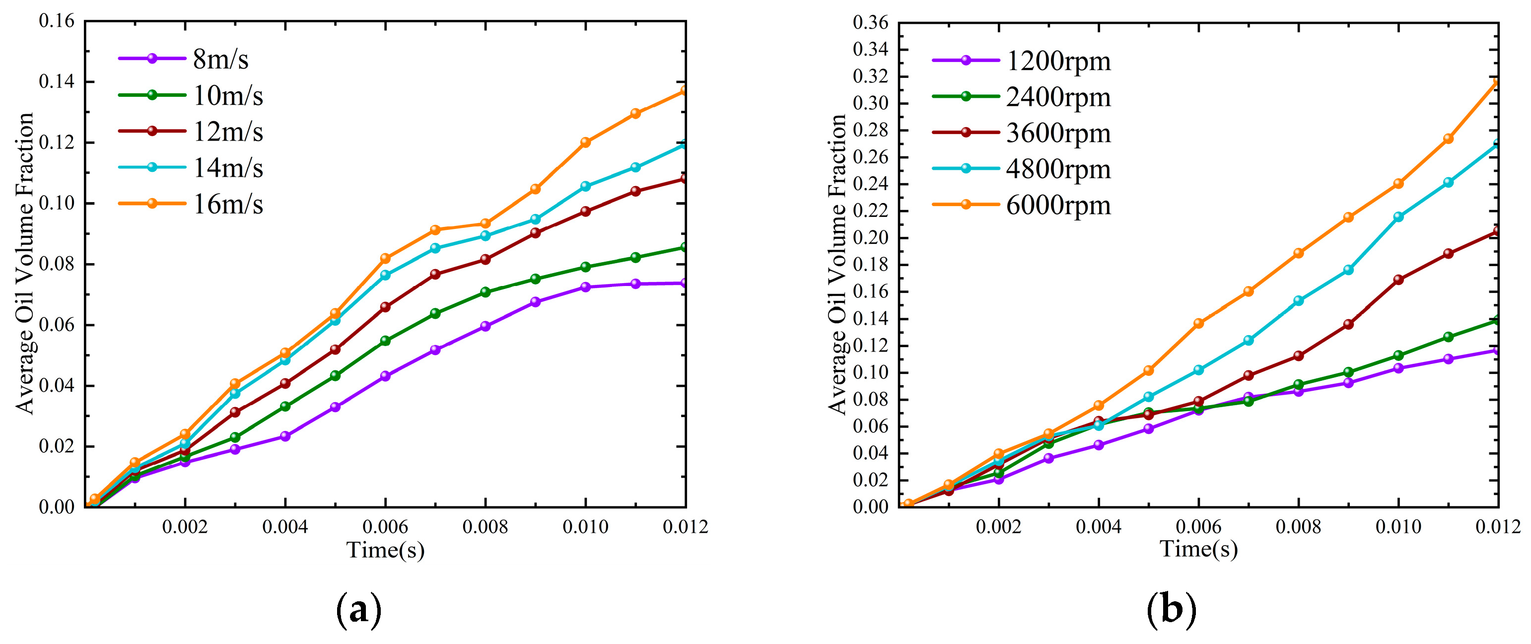
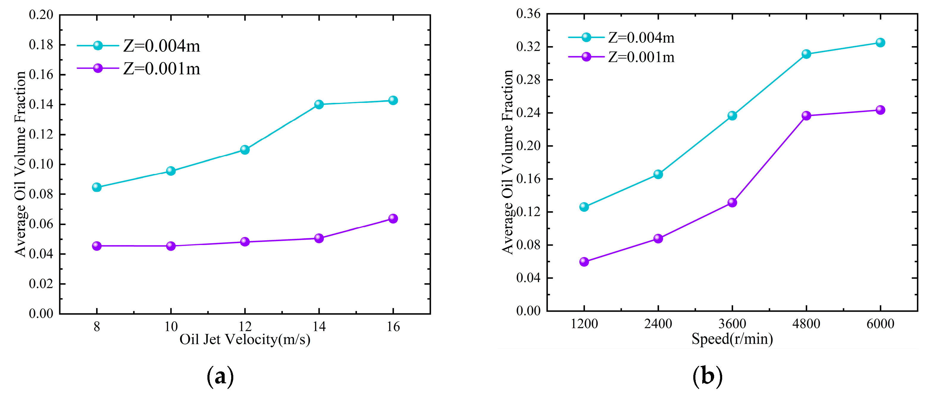
The parametric simulation results of the average oil volume fraction for all roller surfaces can more directly present the influences of different jet velocities and different bearing speeds. It can be seen that the average oil volume fraction rose by 46% as the jet velocity increased from 8 m/s to 16 m/s, as shown in Figure 11a. Furthermore, the average oil volume fraction increased by 63% with the increase in the bearing speed, as shown in Figure 11b. The results also show that the rotational speed had a slightly greater influence than the oil jet velocity. The average oil volume fractions in the cross-sections are displayed in Figure 12. With the rise in the jet velocity from 8 m/s to 16 m/s, the oil in cross-section Z = 0.004 m rose by 0.058, while that in Z = 0.001 m increased slowly by 0.018 because the lubricant sprayed from the nozzle did not diffuse significantly in Z = 0.001 m. The oil volume fraction in cross-section Z = 0.004 m increased at a faster rate than that in cross-section Z = 0.001 m, as shown in Figure 12a. This is because Z = 0.004 m was closer to the nozzle than Z = 0.001 m, making it easier to capture oil. However, with the rise in the rotational speed from 1200 r/min to 6000 r/min, the average volume fractions in Z = 0.001 m and Z = 0.004 m rose by 0.18 and 0.19, respectively. The average oil volume fraction in Z = 0.004 m almost increased at the same rate as that in Z = 0.001 m, as shown in Figure 12b. The reason for this is that the increase in the rotational speed makes the lubricant quickly spread on the surface of the rollers compared with increasing the oil jet velocity.

3.2. Simulation Results and Discussion of Splash Lubrication

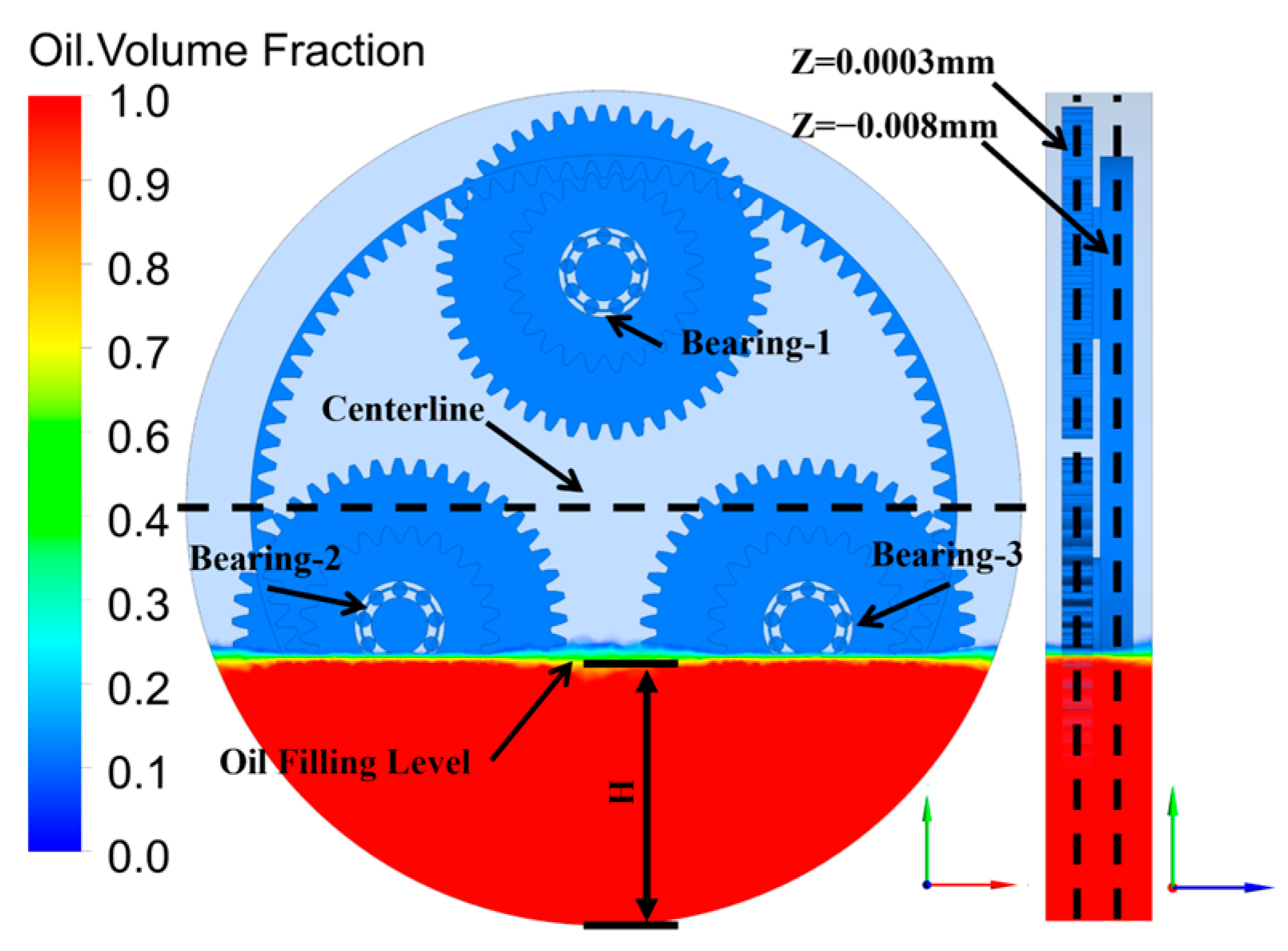
The speed gradient setting of the bearings in the planetary gearbox was the same as for the bearings with oil jet lubrication. The planetary gear speeds were set using the aforementioned formula conversion. To ensure that both the gears and their meshing zones were adequately lubricated, a certain amount of lubricant in the planetary gearbox was needed to form an oil ring. According to the calculation method in reference [28], the oil filling level at H = 52.5 mm was used as a reference. The initial oil filling level was set as shown in Figure 13. While the influence of the bearing speed, which varied from 1200 r/min to 6000 r/min with a gradient of 1200 r/min, was considered for the air-oil transient distribution, the reference level was used as the constant. Furthermore, when the influence of the oil filling level, which varied from 42.5 mm to 62.5 mm with a gradient of 5 mm, was considered for the air-oil transient distribution, the rotational speed at 4800 r/min was used as the constant. The operating conditions of the needle roller bearing in the planetary gearbox with splash lubrication are summarized in Table 5.
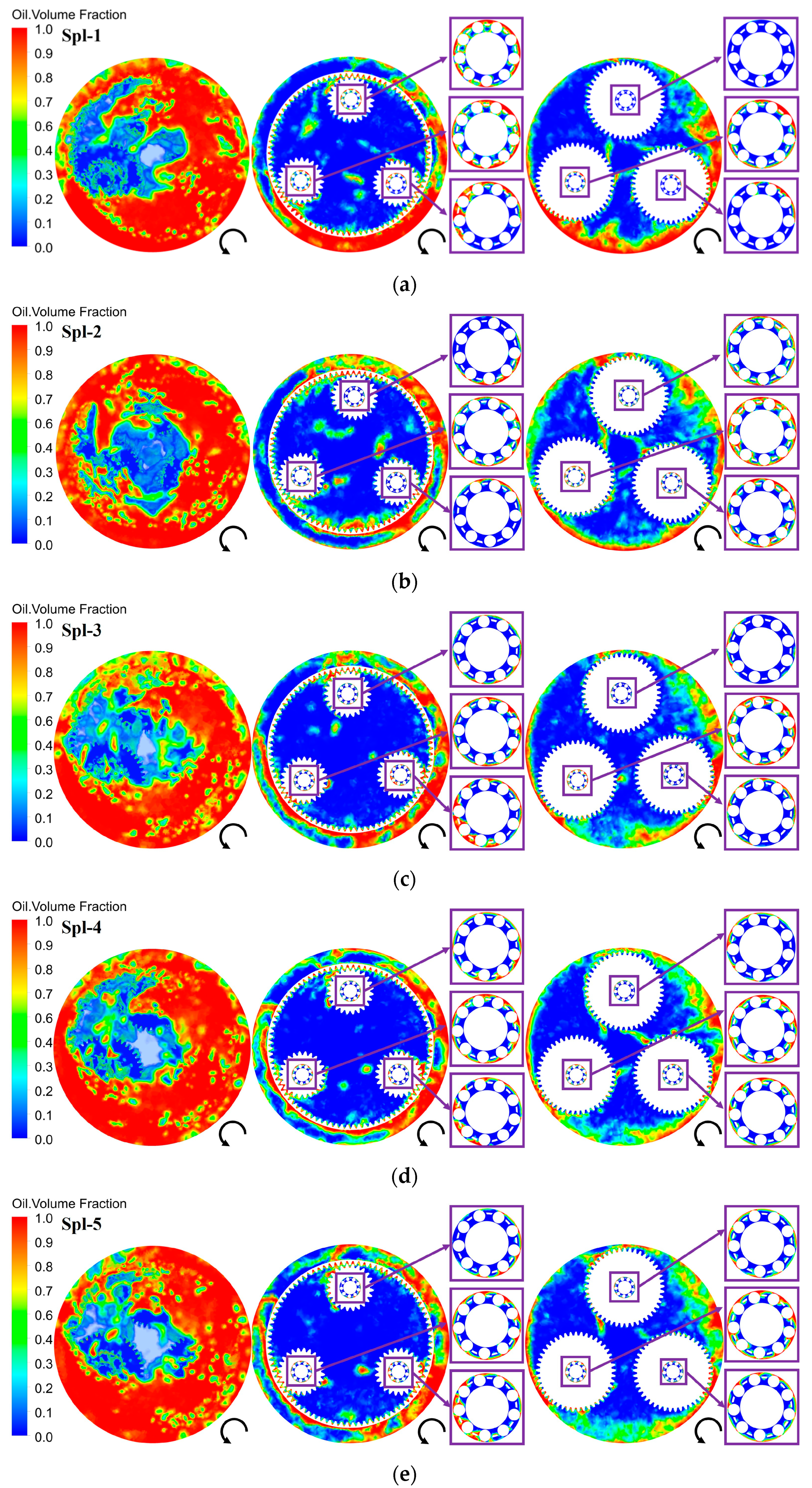
The air-oil transient distribution in the gearbox after one rotation of the planetary gears is shown in Figure 14. It can be observed that the oil was dragged out of the oil sump and continuously churned in the gearbox by the planetary gears. A large amount of oil was thrown into the wall via centrifugal force and formed an oil ring. The cross-sections of Z = − 0.008 mm and Z = 0.0003 mm were selected to observe the lubrication of components inside the gearbox deeply, the positions of which are presented in Figure 13. The cross-sections in Figure 14 illustrate sufficient lubrication for the planetary gears and the ring gear in the gearbox with splash lubrication. However, the needle roller bearings only had a small amount of oil entering the raceways when the planetary gears started to rotate from the standstill position. It can be seen that in the low-speed stage, the sump oil was not sufficiently dragged out. This resulted in a small amount of oil splashing onto the bearing end face as it passed through the oil sump. As the speed increased, the oil was well and rapidly dragged out to the right side of the gearbox, and the bearing passed through the oil sump with little oil entering. The air-oil distributions in the cross-sections indicate that the oil was unevenly distributed in the bearing and was mainly distributed in the contact area of the rollers and the outer ring.
To gain deeper insight into the transient lubrication of the needle roller bearings in the planetary gearbox, the air-oil transient distribution on the surface for components is reported for the considered operating conditions, as shown in Figure 15. The lubrication of the bearings below the centerline of the gearbox was superior to that of the bearing above the centerline in the initial position. This is because the oil filling level was slightly higher than the outer ring of the bearing, and a certain amount of oil entered the raceway at the beginning. The planetary gears had already dragged most of the oil out of the sump before the bearing above the centerline rotated to the bottom. This can well explain why the surfaces of the bearing above the centerline were almost devoid of oil. Moreover, the increase in the bearing speed brought about a decline in the average oil volume fraction in bearing-1 and bearing-2, while that in bearing-3 slowly rose, as shown in the curve diagram below.
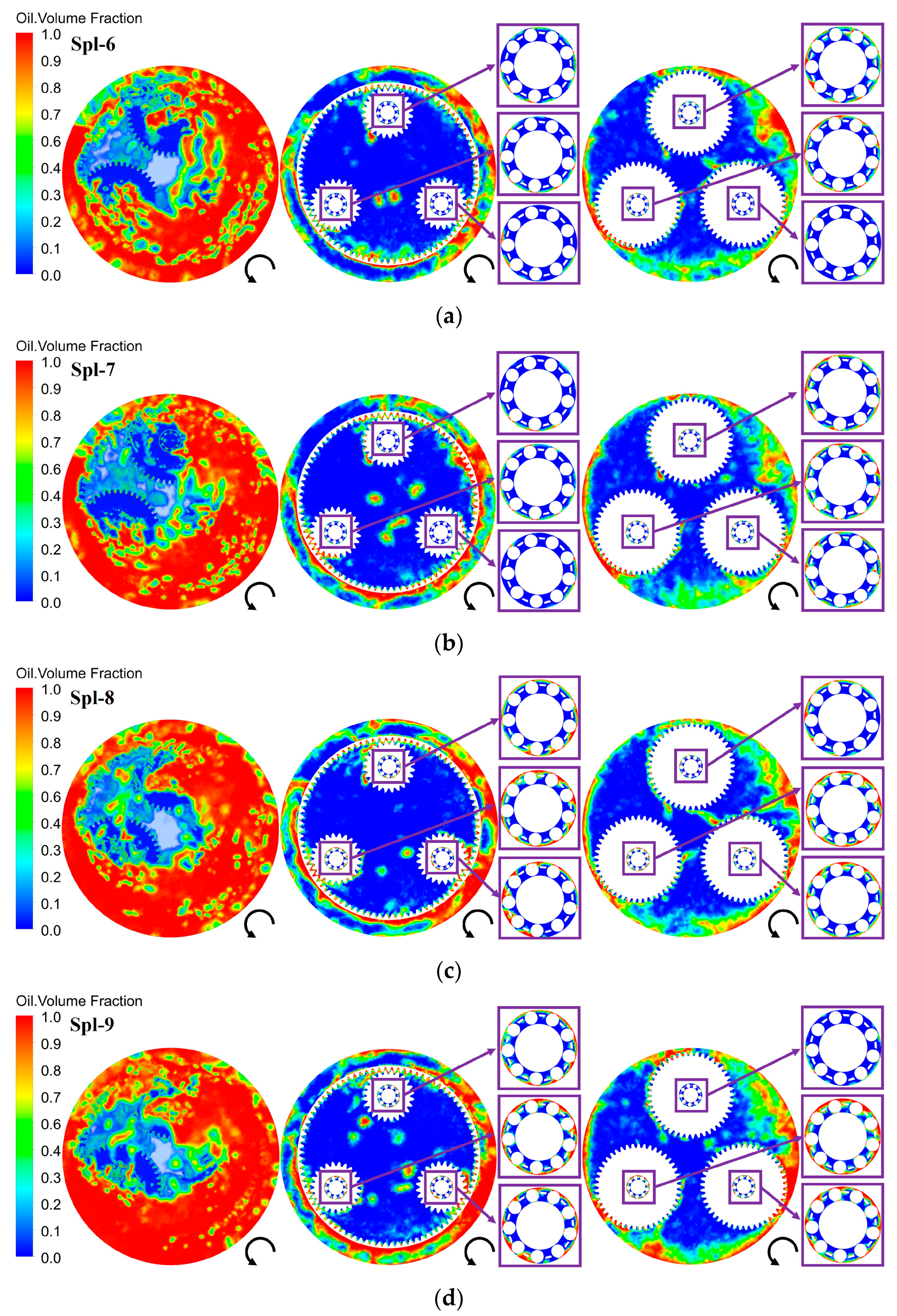
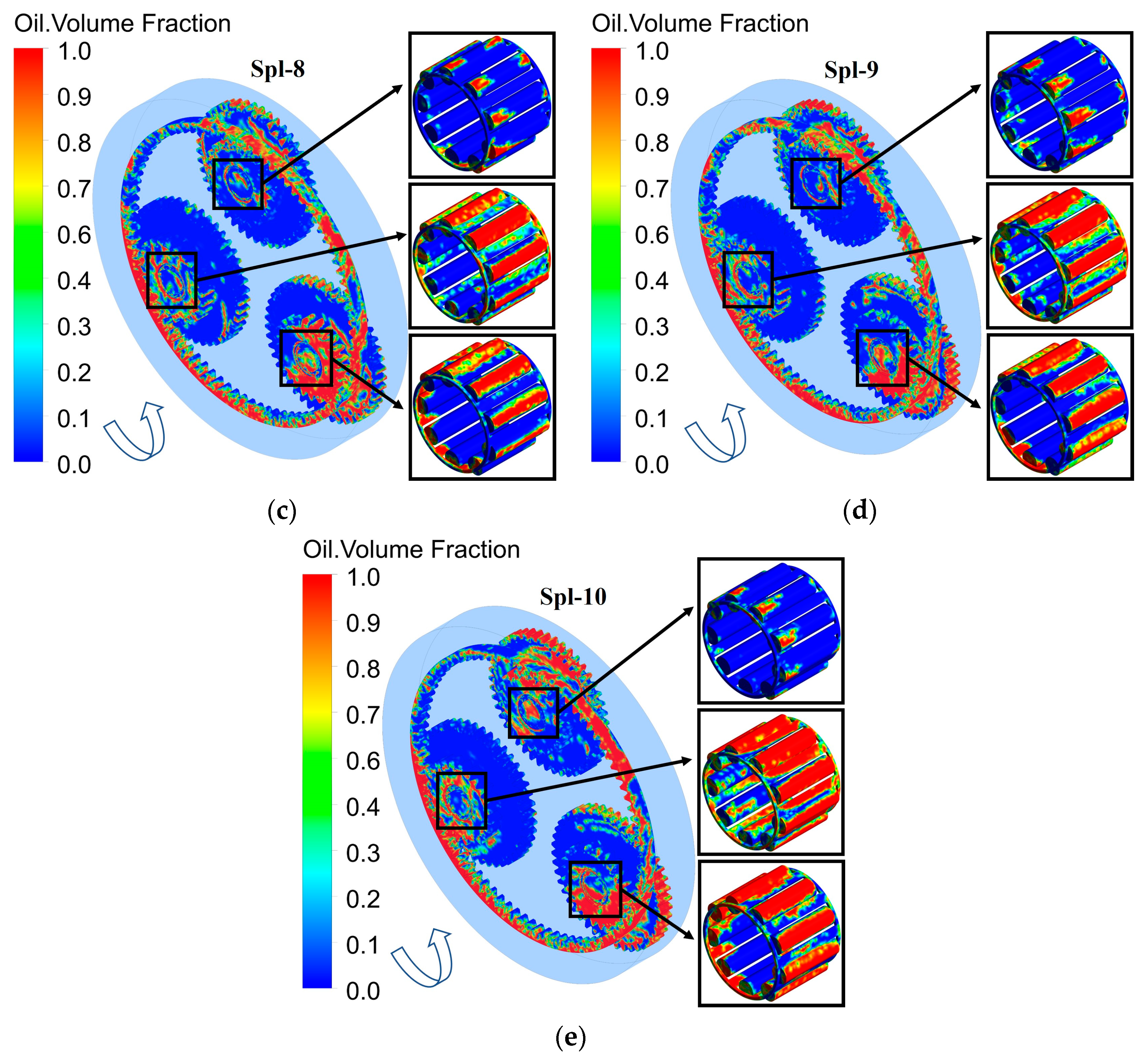
The Spl-6~Spl-10 operating conditions were simulated to investigate the air-oil transient distribution inside the planetary gearbox at different oil filling levels. The air-oil transient distributions after one rotation of the planetary gears are shown in Figure 16. From the view of the transient flow field in the gearbox, the oil was dragged out of the sump and transported to other parts. It can be seen that more oil was splashed axially into the front area of the gearbox and the oil ring became more and more pronounced as the oil filling level increased. The oil ring was not apparent for the low filling levels, such as Spl-6 or Spl-7. The air-oil distributions in the cross-sections demonstrate that it is very difficult for splashed oil to enter the raceways at low oil levels due to the absence of oil in the raceways in the initial position. For the high filling levels, such as Spl-9 or Spl-10, it can be seen that the cross-sections of the bearings below the centerline were filled with a large amount of oil compared with the low filling levels, while that in the bearing above the centerline was almost the same as in Spl-6 and Spl-7.
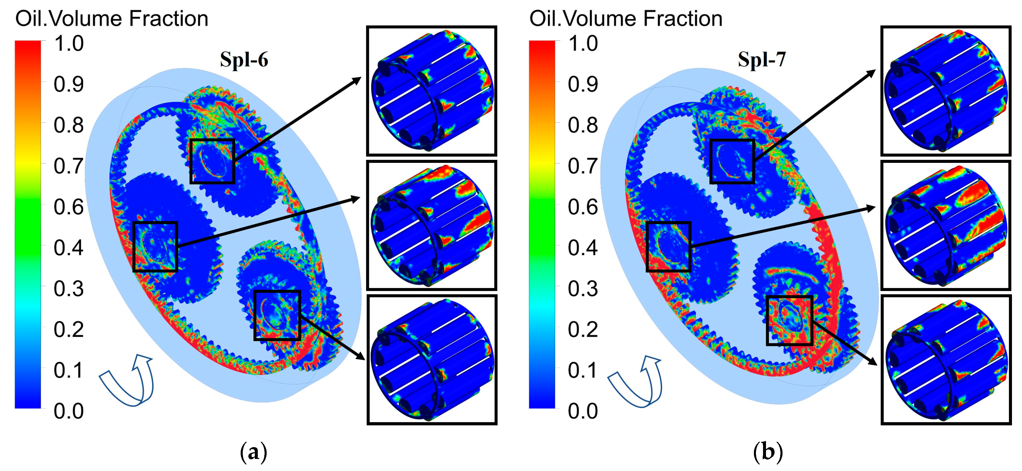
The air-oil transient distributions on the surface are presented for the Spl-6~Spl-10 operating conditions in Figure 17. It can be observed that at low oil levels, there was very little oil on the bearing surfaces and only a small amount of oil on the roller end faces. With the increase in the oil filling level, the lubrication of the bearings below the centerline became better, while that of bearing-1 did not change much. After the beginning, the rapid rotation of the planetary gears kept most of the oil flow circumferentially in the gearbox, and it was difficult to lubricate the needle rollers via the axial flow of the oil when the bearings passed through the oil sump. Based on the above analysis, it can be inferred that this phenomenon is related to the position of the bearings and the oil filling level. On the one hand, elevating the oil level enhances the lubrication of the bearings. On the other hand, it also leads to an increase in the churning power loss.
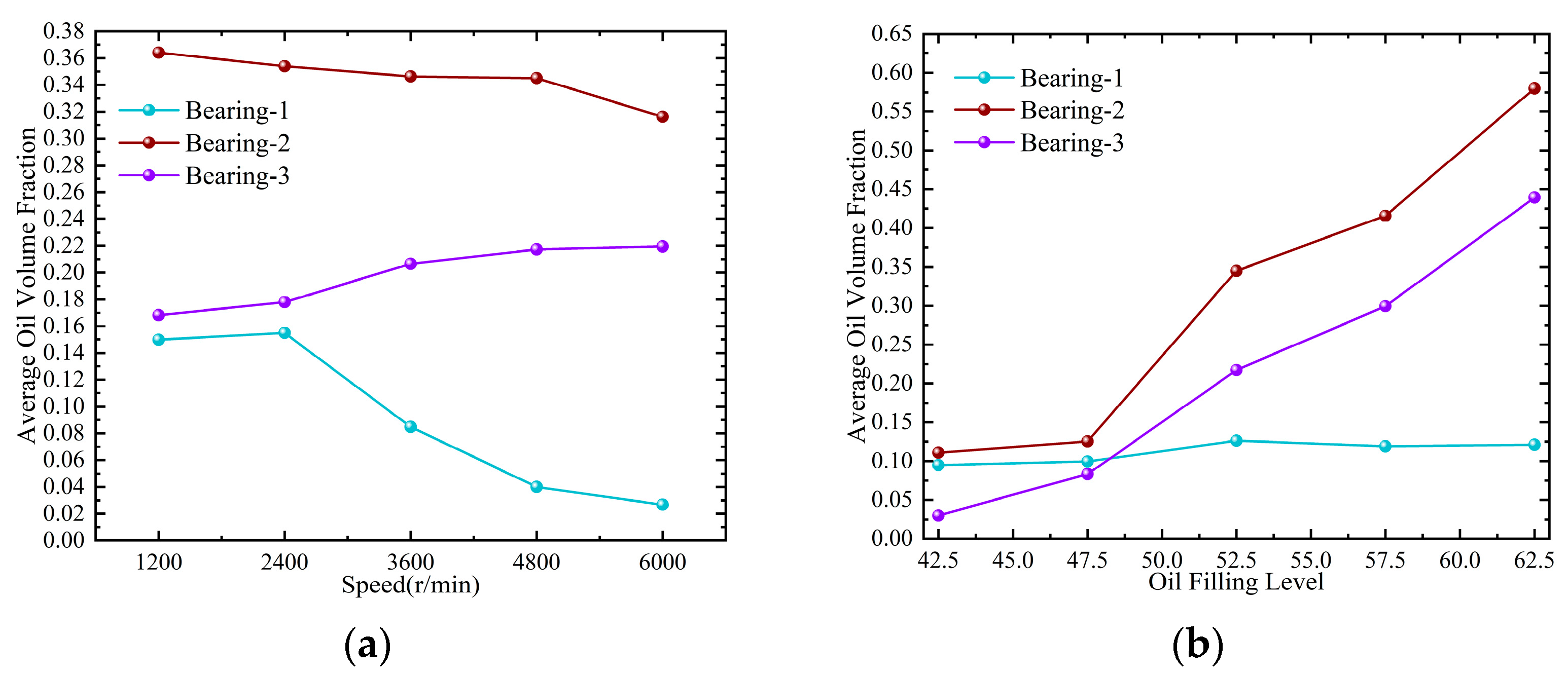
The average oil volume fractions on the roller surfaces with different speeds and oil filling levels are shown in Figure 18. It can be seen that the average oil volume fraction on bearing-2 was more than that on the others and slowly decreased by 13%, while that on bearing-3 increased by 30% with the increase in speed. Furthermore, the average oil volume fraction on bearing-1 decreased by 82%. However, the results present that the average oil volume fractions on bearing-2 and bearing-3 rose rapidly by 0.47 and 0.41, while that on bearing-1 remained essentially stable. Moreover, increasing the oil filling level made the lubrication of the bearings more effective, apart from bearing-1, as shown in Figure 18b.
In this section, the simulation of the transient lubrication of the needle roller bearings inside the planetary gearbox was presented. The influences of speeds and oil filling levels on the splash lubrication of the planetary gearbox were analyzed. In the simulations from Spl-1 to Spl-10, it was consistently noted that irrespective of the speed and oil filling level employed, bearing-1 endured an insufficiency of oil. This may have been caused by the inadequate oil churning of the planetary gears. The reason behind this could be explained by the number of revolutions of the planetary gears. Furthermore, the layout and initial positions of the planetary gears also make a difference. However, there are certain differences and simplifications between the simulation model and the actual operating conditions. The bearings of each branch are fully lubricated after multiple turns of operation for planetary gears during practical operation. In this paper, although the steady state of the flow field could not be completely simulated owing to the computational time and the limitations of the model, the tendency of the flow field still had some good reference values. It can be concluded from Spl-1 to Spl-5 that planetary gears operating at a lower speed for a while are beneficial for the sufficient lubrication of each branch bearing.

3.3. Comparative Analysis of Needle Roller Bearings with Two Types of Lubrication

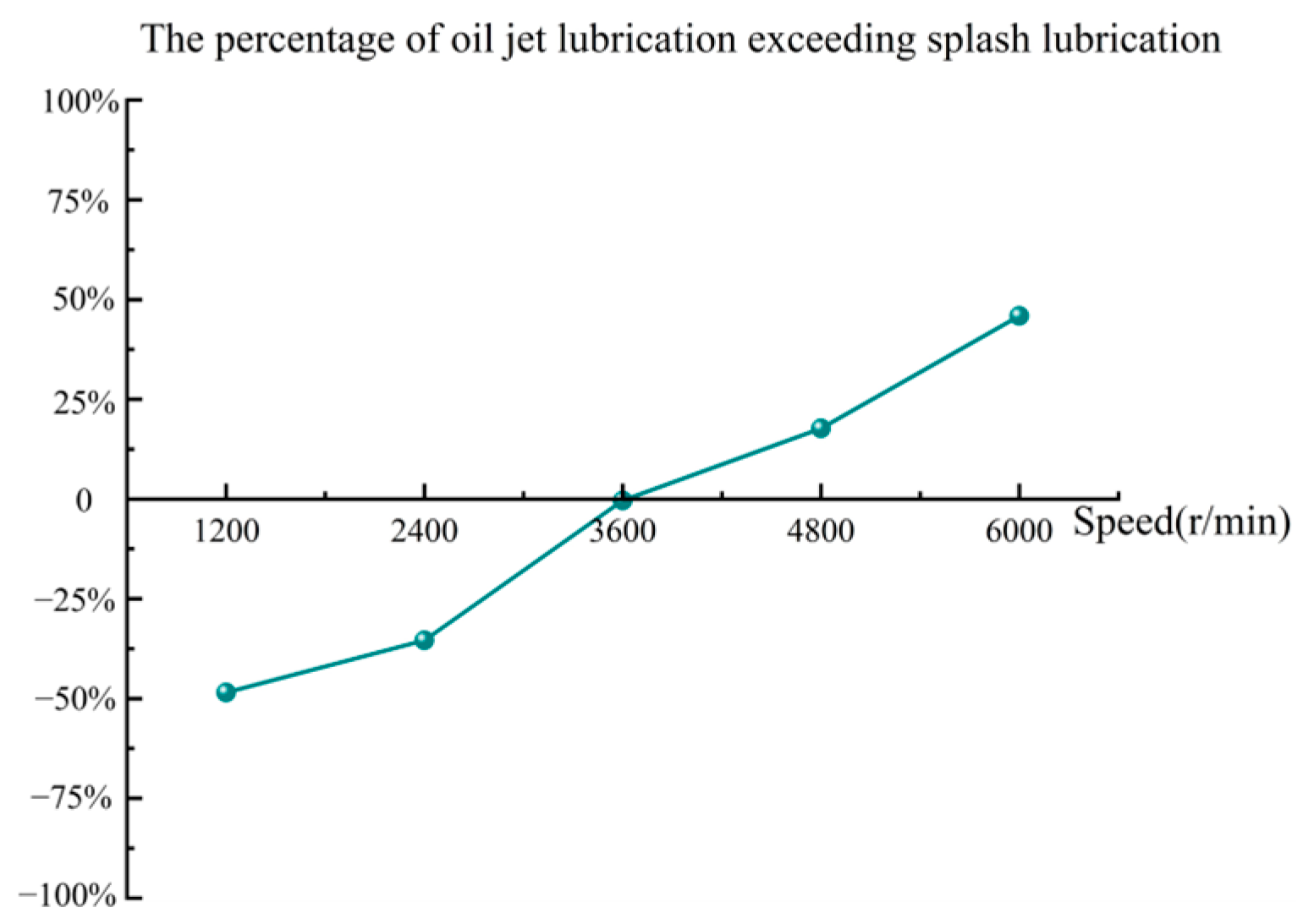
The oil jet lubrication of the needle roller bearings was greatly affected by the rotational speed and, secondly, by the oil jet velocity based on the simulation results. In the case of a reasonable bearing speed and oil jet velocity, bearings could be fully lubricated after a very short period with oil jet lubrication. The splash lubrication of needle roller bearings inside the gearbox was highly dependent on the initial positions of the bearings and the oil filling level. Although raising the speed improved the lubrication of the gears, the average oil volume fractions on bearing-1 and bearing-2 showed a decreasing trend, as shown in Figure 18. When the oil filling level was below the bearings, there was very little lubricant on the rollers, as shown in Figure 14a,b. In contrast with this circumstance, the results of high filling levels are shown in Figure 14d,e. Analyzing Jet-5 and Spl-1 shows that the average volume fractions on bearing-1 and bearing-3 were higher than that on the bearing with oil jet lubrication and increased by 9.2% and 22%. Nevertheless, the average oil volume fractions on bearing-1 and bearing-2 decreased as the speed rose. Comparing Jet-9, Spl-6, and Spl-7, it can be seen that at the same rotational speed, the average volume fraction on every bearing with oil jet lubrication was more than that with splash lubrication and increased by 0.12 and 0.15 when the oil filling levels were at 42.5 mm and 47.5 mm, respectively. However, comparing Jet-9, Spl-9, and Spl-10, the splash lubrication of every bearing in the gearbox was better than oil jet lubrication. The average oil volume fraction on every bearing increased by 0.16 and 0.31 when the oil filling levels were at 57.5 mm and 62.5 mm, respectively. According to Figure 11b and Figure 18a, a comparison curve of the bearing with oil jet lubrication and splash lubrication could be drawn, as shown in Figure 19. This curve selects splash lubrication as the reference, presenting the percentage of oil jet lubrication exceeding splash lubrication. When the lubrication curve is below the horizontal axis, the vertical axis indicates the extent to which oil jet lubrication is lower than splash lubrication. On the contrary, it describes the percentage of oil jet lubrication exceeding splash lubrication. It can be seen that the splash lubrication of the bearings was better than oil jet lubrication while the bearings were at a lower speed. In the high-speed stage, the result was the opposite. Based on the above analysis, it can be concluded that splash lubrication is adverse for high-speed planetary gearboxes. However, a planetary gearbox can be operated at a low speed for a period of time to ensure sufficient lubrication of the bearings before high-speed operation.

4. Conclusions

In this paper, the CFD method was used to predict the air–oil transient distributions of bearings with oil jet lubrication and bearings in a planetary gearbox with splash lubrication. The influences of the oil jet velocities and bearing speeds on oil jet lubrication were investigated. The different oil filling levels and bearing speeds were simulated for the comparative analysis with oil jet lubrication. The reason for the differences between the needle roller bearings with the two kinds of lubrication was analyzed by comparing the simulated results. The main conclusions are as follows:
  • The rotational speed had a significant effect on the oil jet lubrication of the needle roller bearings. The average oil volume fraction rose by 0.2 with the increase in the bearing speed from 1200 r/min to 6000 r/min and by 0.06 with the increase in the oil jet velocity from 8 m/s to 16 m/s. The oil volume fraction on the bearing at a high speed was not very high, but it was well lubricated due to the constant flow of lubricant through the nozzle. A large amount of oil accumulated near the nozzle at lower speeds. Although the oil jet velocity had a great influence on the lubrication, a large amount of oil accumulated near the nozzle at lower speeds.
  • The splash lubrication of the bearings in the planetary gearbox was directly related to the immersion depth of the bearings in the initial position. The increase in speed from 1200 r/min to 6000 r/min made the bearing lubrication decrease by 4.4%. The average oil volume fraction rose by 0.28 with the increase in the oil filling level. In the simulations from Spl-1 to Spl-10, the bearing above the centerline was under insufficient lubrication. This was caused by the inadequate oil churning of the planetary gears. Moreover, there was no apparent change with the speed and oil filling level increases.
  • The average oil volume fraction on the bearings with splash lubrication was better than that with oil jet lubrication by an average of 41.9% when the bearing speed was in the low-speed stage ranging from 1200 r/min to 3600 r/min. On the contrary, the average oil volume fraction on the bearings with oil jet lubrication was better than that with splash lubrication by an average of 31.8% when the bearing speed was in the high-speed stage ranging from 4800 r/min to 6000 r/min.
In summary, although the transient simulations of the oil jet lubrication of the bearings and the splash lubrication of the planetary gearbox were relatively short and the calculations did not reach a steady state, the law of the air-oil distribution state in the fluid domain and the oil volume fraction on the surface had some similarities whether it was transient or steady-state at different bearing speeds, jet velocities, and oil filling levels. Hence, this study still provides reference values for gearbox visualization analysis. Moreover, the evolution of the lubrication law under different working conditions was discussed. Quantitative analysis was beneficial in determining the optimal oil jet quantity under certain working conditions. By comparing the differences and similarities between bearings under two conditions, we explored whether the oil jet lubrication law and results were consistent with those of the splash lubrication of the bearings in the gearbox. These analyses provide reference values for practical engineering applications. In addition, further analysis is needed for the research on the steady state of the bearings in the gearbox with splash lubrication and the validation of the simulation analysis and experimental results.

Author Contributions

Conceptualization, S.G. and X.H.; methodology, S.G. and X.H.; software, S.G., C.M., and Y.Y.; formal analysis, S.G. and Z.L.; investigation, S.G. and X.H.; data curation, R.Y.; writing—original draft preparation, S.G.; supervision, X.H. and R.Z.; funding acquisition, X.H. All authors have read and agreed to the published version of the manuscript.

Funding

This research was funded by the National Natural Science Foundation of China (grant no. 52105060), the Natural Science Foundation of Jiangsu Province of China (grant no. BK 20200428), and the Special Transmission Project (grant no. KY-1044-2023-0458).

Data Availability Statement

All the data are shown in the tables and figures of this paper.

Conflicts of Interest

The authors declare no conflicts of interest.

References

  1. Kumar, S.; Kumar, V.; Singh, A.K. Influence of lubricants on the performance of journal bearings—A review. Tribol. Mater. Surf. Interfaces 2020, 14, 67–78. [Google Scholar] [CrossRef]
  2. Li, Y.; Ai, Y.; Liu, W.; Pan, W.; Hu, Y. Splash lubrication simulation analysis and verification of a gearbox based on CFD. J. Aerosp. Power 2020, 35, 1482–1488. [Google Scholar] [CrossRef]
  3. Wittbrodt, M.J.; Pechersky, M.J. Hydrodynamic analysis of fluid flow between meshing spur gear teeth. J. Mech. Des. 1990, 111, 395–401. [Google Scholar] [CrossRef]
  4. Pinel, S.I.; Signer, H.R.; Zaretsky, E.V. Comparison between oil-mist and oil-jet lubrication of high-speed, small-bore, angular-contact ball bearings. Tribol. Trans. 2001, 44, 327–338. [Google Scholar] [CrossRef]
  5. Zhong, J.; Dai, Y.; Liang, C.; Zhu, X.; Xu, L. CFD investigation of air-oil two-phase flow in oil jet nozzle. Proc. Inst. Mech. Engineers. Part C J. Mech. Eng. Sci. 2022, 236, 10079–10089. [Google Scholar] [CrossRef]
  6. Liu, H.; Jurkschat, T.; Lohner, T.; Stahl, K. Determination of oil distribution and churning power loss of gearboxes by finite volume CFD method. Tribol. Int. 2017, 109, 346–354. [Google Scholar] [CrossRef]
  7. Lu, F.; Wang, M.; Pan, W.; Bao, H.; Ge, W. CFD-based investigation of lubrication and temperature characteristics of an intermediate gearbox with splash lubrication. Appl. Sci. 2021, 11, 352. [Google Scholar] [CrossRef]
  8. Maccioni, L.; Concli, F. Computational fluid dynamics applied to lubricated mechanical components: Review of the approaches to simulate gears, bearings, and pumps. Appl. Sci. 2020, 10, 8810. [Google Scholar] [CrossRef]
  9. Keller, M.C.; Kromer, C.; Cordes, L.; Schwitzke, C.; Bauer, H. CFD study of oil-jet gear interaction flow phenomena in spur gears. Aeronaut. J. 2020, 124, 1301–1317. [Google Scholar] [CrossRef]
  10. Peterson, W.; Russell, T.; Sadeghi, F.; Berhan, M.T.; Stacke, L.; Ståhl, J. A CFD investigation of lubricant flow in deep groove ball bearings. Tribol. Int. 2021, 154, 106735. [Google Scholar] [CrossRef]
  11. Liu, H.; Hao, J.; Jia, Q.; Yang, M.; Shen, Z. Oil atomization analysis of jet lubrication for high speed angular contact ball bearing. J. Aerosp. Power 2020, 35, 1186–1194. [Google Scholar] [CrossRef]
  12. Liu, H.; Wang, H.; Zhang, L.; Shi, Y.; Liu, G. Analysis on penetration mechanism of oil jet lubrication for high speed rolling bearing. J. Aerosp. Power 2016, 31, 1766–1776. [Google Scholar] [CrossRef]
  13. Zheng, D.; Gu, L.; Wang, L.; Wei, Y. Effect of lubrication oil supply parameters on the performance of high-speed rolling bearing. J. Harbin Inst. Technol. 2006, 38, 11–14. [Google Scholar]
  14. Zhang, R.; Wei, C.; Wu, W.; Yuan, S.H. CFD Investigation on the Influence of Jet Velocity of Oil-jet Lubricated Ball Bearing on the Characteristics of Lubrication Flow Field. In Proceedings of the International Conference on Fluid Power and Mechatronics FPM, Harbin, China, 5–7 August 2015; pp. 1324–1328. [Google Scholar] [CrossRef]
  15. Liu, J.; Xu, Z. A simulation investigation of lubricating characteristics for a cylindrical roller bearing of a high-power gearbox. Tribol. Int. 2022, 167, 107373. [Google Scholar] [CrossRef]
  16. Wu, W.; Hu, C.; Hu, J.; Yuan, S. Jet cooling for rolling bearings: Flow visualization and temperature distribution. Appl. Therm. Eng. 2016, 105, 217–224. [Google Scholar] [CrossRef]
  17. Wu, W.; Hu, C.; Hu, J.; Yuan, S.; Zhang, R. Jet cooling characteristics for ball bearings using the VOF multiphase model. Int. J. Therm. Sci. 2017, 116, 150–158. [Google Scholar] [CrossRef]
  18. Wu, W.; Hu, J.; Yuan, S.; Hu, C. Numerical and experimental investigation of the stratified air-oil flow inside ball bearings. Int. J. Heat Mass Transf. 2016, 103, 619–626. [Google Scholar] [CrossRef]
  19. Moshammer, T.; Mayr, F.; Kargl, K.; Honeger, C. Simulation of oil flow in gear box housing. SAE Tech. Pap. Ser. 2006, 1486–1494. [Google Scholar] [CrossRef]
  20. Concli, F.; Gorla, C. Numerical modeling of the churning power losses in planetary gearboxes: An innovative partitioning-based meshing methodology for the application of a computational effort reduction strategy to complex gearbox configurations. Lubr. Sci. 2017, 29, 455–474. [Google Scholar] [CrossRef]
  21. Höhn, B.; Michaelis, K.; Otto, H. Influence of immersion depth of dip lubricated gears on power loss, bulk temperature and scuffing load carrying capacity. Int. J. Mech. Mater. Des. 2008, 4, 145–156. [Google Scholar] [CrossRef]
  22. Mastrone, M.N.; Hildebrand, L.; Paschold, C.; Lohner, T.; Stahl, K.; Concli, F. Numerical and experimental analysis of the oil flow in a planetary gearbox. Appl. Sci. 2023, 13, 1014. [Google Scholar] [CrossRef]
  23. Liu, H.; Standl, P.; Sedlmair, M.; Lohner, T.; Stahl, K. Efficient CFD simulation model for a Planetary gearbox. Forsch. Im Ingenieurwesen 2018, 82, 319–330. [Google Scholar] [CrossRef]
  24. Hirt, C.W.; Nichols, B.D. Volume of fluid (VOF) method for the dynamics of free boundaries. J. Comput. Phys. 1981, 39, 201–225. [Google Scholar] [CrossRef]
  25. Li, L.; Versteeg, H.K.; Hargrave, G.K.; Potter, T.; Halse, C. Numerical investigation on fluid flow of gear lubrication. SAE Int. J. Fuels Lubr. 2009, 1, 1056–1062. [Google Scholar] [CrossRef]
  26. Liu, H.; Jurkschat, T.; Lohner, T.; Stahl, K. Detailed investigations on the oil flow in dip-lubricated gearboxes by the finite volume CFD method. Lubricants 2018, 6, 47. [Google Scholar] [CrossRef]
  27. Zhu, W.; Zhang, X.; Lu, Y.; Wang, D. Numerical Study for Influence of Lubrication Methods on Lubrication Performance of Ball Bearing. J. Propuls. Technol. 2019, 40, 892–901. [Google Scholar] [CrossRef]
  28. Boni, J.B.; Changenet, C.; Ville, F. Analysis of flow regimes and associated sources of dissipation in splash lubricated planetary gear sets. J. Tribol. 2021, 143, 111805. [Google Scholar] [CrossRef]
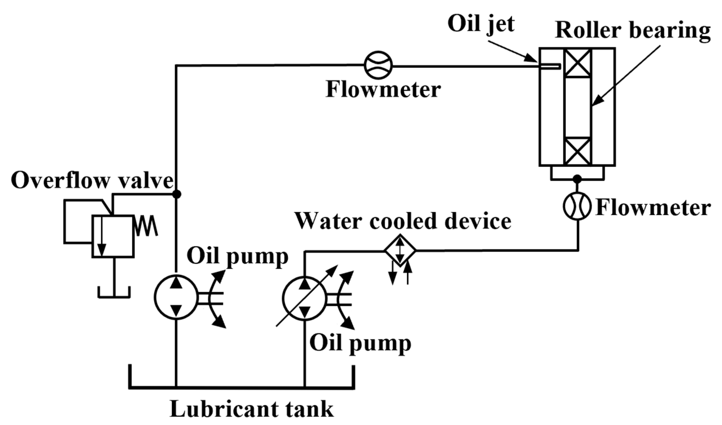
Figure 1. The diagram of the principle of an oil jet lubrication system.
Lubricants 12 00039 g001
Figure 2. Computational domain of the needle roller bearing with oil jet lubrication: (a) isometric view; (b) front view; and (c) fluid domain.
Lubricants 12 00039 g002
Figure 3. Computational domain of the needle roller bearing in the planetary gearbox with splash lubrication: (a) simplified model; (b) planetary gearbox system.
Lubricants 12 00039 g003
Figure 4. Fluid domain meshing in the needle roller bearing with oil jet lubrication.
Lubricants 12 00039 g004
Figure 5. Fluid domain meshing in the planetary gearbox with splash lubrication.
Lubricants 12 00039 g005
Figure 6. Schematic representation of the positions of cross-sections Z = 0.001 m and Z = 0.004 m in the fluid domain.
Lubricants 12 00039 g006
Figure 7. Air-oil distributions inside the bearing at different jet velocities; The black arrow indicates the direction of rotation: (a) Jet-1; (b) Jet-2; (c) Jet-3; (d) Jet-4; and (e) Jet-5.
Lubricants 12 00039 g007
Figure 8. Oil volume fraction contours in cross-section Z = 0.001 m and cross-section Z = 0.004 m at different jet velocities; The black arrow indicates the direction of rotation: (a) Jet-6; (b) Jet-7; (c) Jet-8; (d) Jet-9; and (e) Jet-10.
Lubricants 12 00039 g008
Figure 9. Air-oil distributions inside the bearing at different speeds: (a) Jet-6; (b) Jet-7; (c) Jet-8; (d) Jet-9; and (e) Jet-10.
Lubricants 12 00039 g009aLubricants 12 00039 g009b
Figure 10. Oil volume fraction contours in cross-section Z = 0.001 m and cross-section Z = 0.004 m at different speeds: (a) Jet-6; (b) Jet-7; (c) Jet-8; (d) Jet-9; and (e) Jet-10.
Lubricants 12 00039 g010
Figure 11. Average oil volume fractions on the roller surfaces: (a) oil volume fractions at different jet velocities; (b) oil volume fractions at different bearing speeds.
Lubricants 12 00039 g011
Figure 12. Average oil volume fractions of the cross-sections: (a) average oil volume fractions in the cross-sections at the different oil jet velocities; (b) average oil volume fractions in the cross-sections at the different speeds.
Lubricants 12 00039 g012
Figure 13. Initial oil filling level setting and the positions of cross-sections.
Lubricants 12 00039 g013
Figure 14. Air-oil distributions inside the planetary gearbox at different speeds; The black arrow indicates the direction of rotation: (a) Spl-1; (b) Spl-2; (c) Spl-3; (d) Spl-4; and (e) Spl-5.
Lubricants 12 00039 g014
Figure 15. Air-oil distributions on the surfaces inside the planetary gearbox at different speeds; The white arrow indicates the direction of rotation: (a) Spl-1; (b) Spl-2; (c) Spl-3; (d) Spl-4; and (e) Spl-5.
Lubricants 12 00039 g015
Figure 16. Air-oil distributions inside the planetary gearbox at different oil filling levels: (a) Spl-6; (b) Spl-7; (c) Spl-8; (d) Spl-9; and (e) Spl-10.
Lubricants 12 00039 g016aLubricants 12 00039 g016b
Figure 17. Air-oil distributions on the surface inside the planetary gearbox at different oil filling levels: (a) Spl-6; (b) Spl-7; (c) Spl-8; (d) Spl-9; and (e) Spl-10.
Lubricants 12 00039 g017aLubricants 12 00039 g017b
Figure 18. Average oil volume fractions on the roller surfaces: (a) average oil volume fractions with different speeds; (b) average oil volume fractions with different oil filling levels.
Lubricants 12 00039 g018
Figure 19. Comparison curve of the bearing with splash lubrication and oil jet lubrication.
Lubricants 12 00039 g019
Table 1. Values of structural parameters of needle roller bearings.
ParameterValue
Outer diameter (mm)18
Inner diameter (mm)12
Width (mm)14
Number of rollers9
Table 2. Structural parameter values of planetary gearboxes.
ParameterPlanetary Gear 1Planetary Gear 2Ring Gear
Modulus (mm)1.51.51.5
Number of teeth452487
Pressure angle (°)202020
Tooth width (mm)6.56.56.5
Table 3. Properties of the lubricant.
ParameterSymbolFVA4
ISO VG-460
Density at 40 °C in kg/m3ρ (15 °C)882
Kinematic viscosity at 40 °C in mm2/sν (40 °C)480
Kinematic viscosity at 100 °C in mm2/sν (100 °C)31.5
Table 4. Operating conditions of the oil jet lubrication.
Simulation
Name
LubricantFluid Domain Temperature in °COil Jet Velocity in m/sBearing Speed in rpm
Jet-1FVA44081200
Jet-210
Jet-312
Jet-414
Jet-516
Jet-6121200
Jet-72400
Jet-83600
Jet-94800
Jet-106000
Table 5. Operating conditions of the splash lubrication.
Simulation
Name
LubricantOil Sump Temperature in °CBearing Speed in r/minOil Filling Level in mm
Spl-1FVA440120052.5
Spl-22400
Spl-33600
Spl-44800
Spl-56000
Spl-6480042.5
Spl-747.5
Spl-852.5
Spl-957.5
Spl-1062.5
Disclaimer/Publisher’s Note: The statements, opinions and data contained in all publications are solely those of the individual author(s) and contributor(s) and not of MDPI and/or the editor(s). MDPI and/or the editor(s) disclaim responsibility for any injury to people or property resulting from any ideas, methods, instructions or products referred to in the content.