Article

Dynamic-Projection-Integrated Particle-Filtering-Based Identification of Friction Characteristic Curve for Train Wheelset on Slipping Fault Condition

1
School of Automation, Central South University, Changsha 410083, China
2
CRSC Research & Design Institute Group Co., Ltd., Beijing 100071, China
*
Authors to whom correspondence should be addressed.
Lubricants 2024, 12(2), 38; https://doi.org/10.3390/lubricants12020038
Submission received: 1 December 2023 / Revised: 19 January 2024 / Accepted: 23 January 2024 / Published: 27 January 2024

Abstract

:
This paper proposes a dynamic-projection-integrated particle-filtering-based identification strategy for the friction characteristic curve of a train wheelset under the slipping fault condition. This strategy aims to achieve the identification of the fault friction characteristic curve (FFCC) in the early slipping fault stage. First, a multi-dimensional integrated particle-filtering (MDIPF)-based parameters correction method is proposed. The MDIPF constructs an error particle state transition model encompassing multi-dimensional parameters, which integrates inter-particle correlation to facilitate error fusion during the state transition process. Then, a dynamic projection domain (DPD)-based particle refinement method is proposed. The DPD constructed the contraction factors to dynamically fine-tune the particle projection domain. Finally, a multi-level evaluation-based identification method for the FFCC is proposed. And the dynamic-projection-integrated particle-filtering-based identification strategy is validated, which can actualize the rapid and accurate identification of the FFCC.

1. Introduction

As the wheelset is the sole component connecting train and rail, the safe operation of the wheelset is critical [1,2]. It is of utmost importance to maintain the friction force between the wheelset and the rail within a controllable and permissible range [3,4]. However, prolonged operation of the train results in wear and tear of both the wheelset and the rail. This will lead to the slipping fault, causing a sudden decrease in friction force. The slipping fault can lead to the wheelset entering an unstable state, potentially causing catastrophic accidents. It is imperative to promptly and accurately identify the friction characteristic curve under varying degrees of the slipping fault [5]. This enables the determination of the friction force that can be provided between the wheelset and the rail.
The wheelset status includes normal operating status and early and serious fault status. Moreover, the duration of the wheelset’s slipping fault during the early stage is extremely brief [6]. This necessitates a highly rapid and precise system for identifying the fault friction characteristic curve (FFCC) [7].
Significant progress has been made in the identification methods of the FFCC [8,9]. These identification methods primarily focus on cause-based identification and effect-based identification [10,11]. The cause-based identification methods require the installation of additional specific sensors to gather information from the wheelset-rail interface. In [12], a simple cantilever-type tactile sensor is directly installed on the wheelset for friction force measurement. In [13], a vehicle-mounted camera-based identification method for the FFCC is proposed. In [14], ultrasonic transmitters and receivers are employed to emit and capture ultrasonic signals of varying frequencies. By analyzing the acoustic signal characteristics at different frequencies, the identification of the FFCC can be performed. However, these methods require the installation of additional sophisticated sensors, which increases the application cost.
Compared to cause-based identification methods, effect-based identification methods can leverage existing onboard sensors [15,16]. In [17], five types of friction characteristic curves are predefined, and the identification is performed by comparing the difference between the estimated friction coefficient and the friction coefficient of the predefined curve. In [18], a total of six types of friction characteristic curves are constructed, and the curve type is identified based on the area of the closed interval between the slip ratio and the friction coefficient. In [19], the error between the estimated friction coefficient and the set friction coefficient is statistically evaluated over a certain time interval, and identification is carried out based on the principle of minimizing the statistical error. However, these methods are limited to the predefined curves and cannot accurately identify other unknown FFCC.
Indeed, there are also effect-based methods available for the identification of the unknown FFCC [20,21]. In [22], an adaptive sliding mode observer is proposed to estimate the unknown parameters of the FFCC. In [23], a novel linear parametric model obtained through extreme learning machine is proposed, and the model enables the identification of the FFCC through recursive least squares algorithm. In [24], an improved identification model is proposed, and the pressure distribution function of loading in the model is modified as a non-uniform distribution pattern for estimating the friction coefficient. In [25], the initial parameters are transformed using fuzzy rules, and the unknown parameters of the FFCC are identified by the non-linear least squares method. However, the time for a fault wheelset to deteriorate from the early stage to the serious stage is very short. It is difficult to accurately identify the FFCC with these methods within such a limited time.
In this paper, a dynamic-projection-integrated particle-filtering-based identification strategy of the FFCC for train wheelset is proposed. The main innovations are as follows:
  • A multi-dimensional integrated particle-filtering (MDIPF)-based parameters correction method is proposed. The MDIPF constructs an error particle state transition model encompassing multi-dimensional parameters. The model effectively integrates inter-particle correlation to facilitate error fusion during the state transition process, which accelerates the correction speed of error parameters in the FFCC.
  • A dynamic projection domain (DPD)-based particle refinement method is proposed. The DPD comprehensively considers the impact of multi-dimensional edge error particles on the identification speed of the FFCC. The iterative correction quantities are restructured into contraction factors to dynamically fine-tune the particle projection domain, which effectively improves the convergence speed for identifying the FFCC.
  • A multi-level evaluation-based identification method for the FFCC is proposed. And the proposed identification strategy is validated, which could actualize rapid and accurate identification of the FFCC.
Section 2 introduces the wheelsets–rail friction principle. Then, in Section 3, the dynamic-projection-integrated particle-filtering-based identification strategy of the FFCC is elaborated. In Section 4, the proposed identification strategy is validated by a hardware-in-the-loop platform. The Section 5 provides an overview of the proposed identification strategy.

2. Wheelsets–Rail Friction Principle and Analysis of Fault Friction Characteristic Curve

2.1. Wheelsets–Rail Friction Principle

Figure 1 is the schematic diagram of friction [6]. There is always a certain amount of creep between the wheelset and the rail, which leads to inconsistent speed between the train and wheelset. The expression of the inconsistent speed v s is as follows:
v s = w f a u · r f a u v t
where w f a u is the speed of the faulty wheelset, r f a u is the radius of the faulty wheelset, v t is the train speed, v s is the creep speed.
The expression of friction force F f a u is as follows:
F f a u = μ ( v s ) · T W · g
where μ ( v s ) is the friction coefficient, T W is the axle load of the faulty wheelset, and g is the gravitational acceleration.

2.2. Analysis of Fault Friction Characteristic Curve

The expressions of the normal friction characteristic curve (NFCC) and the fault friction characteristic curve (FFCC) are as follows:
M v s , λ 00 , λ i 0 , τ j 0 N o r 0 = i = 1 , j = 1 n λ 00 + λ i 0 e τ j 0 · v s M v s , λ 0 , λ i , τ j F a u = i = 1 , j = 1 n λ 0 + λ i e τ j · v s
where M v s , λ 00 , λ i 0 , τ j 0 N o r 0 is the NFCC with respect to v s , λ 00 , λ i 0 , τ j 0 ; and λ 00 , λ i 0 , τ j 0 are parameters of the NFCC; M v s , λ 0 , λ i , τ j F a u is the th FFCC with respect to v s , λ 0 , λ i , τ j ; λ 0 , λ i , τ j are parameters of the th FFCC, i = 1 , 2 , n , j = 1 , 2 , n , = 1 , 2 , n .
λ 0 is the constant term associated with the th FFCC; λ i is the exponential term weight coefficient associated with the th FFCC, dictating the influence of different exponential terms on the trend of FFCC variations; τ j is the exponential term coefficient associated with the th FFCC, dictating the growth and decay rates of the exponential term relative to the creep speed v s ; different λ 0 , λ i , and τ j represent different severity levels of the FFCC.
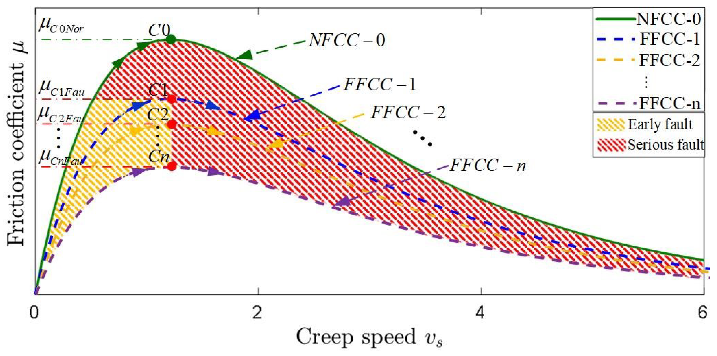
As shown in Figure 2, under the normal friction condition, the friction coefficient of the wheelset operates according to the NFCC-0. The friction coefficient of the wheelset is always less than or equal to the maximum friction coefficient μ C 0 N o r of the NFCC-0. The wheelset remains in a stable rotating state.
When the wheelset experiences the slipping fault, the friction coefficient of the faulty wheelset will operate according to the FFCC. The maximum friction coefficient of the FFCC is unknown. It could be μ C 1 F a u , μ C 2 F a u , , μ C n F a u . And the maximum friction force that the wheelset can provide may be F C 1 F a u , F C 2 F a u , , F C n F a u . In the case of unknown maximum friction force of the wheelset, it becomes challenging to maintain the faulty wheelset within a controllable operating range. This will lead to the rapid deterioration of the faulty wheelset from the early stage to the serious stage.

3. Dynamic-Projection-Integrated Particle-Filtering-Based Identification of the FFCC

3.1. Estimation of the Friction Coefficient of the Faulty Wheelset

The identification of the FFCC requires obtaining the friction coefficient from the faulty wheelset. The friction coefficient is calculated through the estimated load torque. And the expression of the load torque observer of the faulty wheelset is as follows:
x ^ L F a u k + 1 = ( A L F a u T + 1 ) x ^ L F a u k + B L F a u T u L F a u k + H L F a u T y L F a u k y ^ L F a u k y ^ L F a u k = C L F a u x ^ L F a u k
where A μ F a u , B μ F a u , C μ F a u , H μ F a u are the matrices of the state, input, output, feedback gain; x ^ μ F a u k , y ^ μ F a u k , u μ F a u k are the variables of the state, output, control at the kth instant; x ^ μ F a u k + 1 is the state variable at the ( k + 1 ) th instant; y μ F a u k is the actual measured value of the speed of the faulty wheelset at the kth instant; and T is the sampling time. The detailed explanation of relevant variables is provided in Appendix A.
By selecting the appropriate feedback gain matrix H μ F a u , the estimation of the kth load torque T ^ L F a u ( k ) is realized. And the friction coefficient of the faulty wheelset is calculated using the following expression:
μ F a u ( k ) = T ^ L F a u ( k ) · η · R g T ^ L F a u ( k ) · η · R g r · T W · g r f a u · T W · g
where μ F a u ( k ) is the friction coefficient of the faulty wheelset at the kth instant.

3.2. Nonlinear Least Squares-Based Preliminary Identification of the FFCC

Based on the friction coefficient of the faulty wheelset, the parameters of the FFCC are preliminarily identified by the nonlinear least squares (NLLS) method.
The preliminary identification of the FFCC is defined as follows:
M v s , λ ^ 0 p r e , λ ^ i p r e , τ ^ j p r e F a u = i = 1 , j = 1 n λ ^ 0 p r e + λ ^ i p r e e τ ^ j p r e · v s
where M v s , λ ^ 0 p r e , λ ^ i p r e , τ ^ j p r e F a u is the initial FFCC with respect to v s , λ ^ 0 p r e , λ ^ i p r e , τ ^ j p r e ; and λ ^ 0 p r e , λ ^ i p r e , τ ^ j p r e are parameters of the initial FFCC to be identified.
We define the objective function of the NLLS for identifying the parameters of the initial FFCC:
ϑ = l 1 = 1 L μ F a u l 1 M v s l 1 , λ ^ 0 p r e , λ ^ i p r e , τ ^ j p r e F a u .
The optimization function of the NLLS for identifying the parameters of the initial FFCC is as follows:
min Φ = ϑ + Λ T s + 1 2 Λ T H Λ s . t . Λ ρ
where s is the gradient, H is the Hessian matrix, Λ is the search step size, and ρ is the search radius.
By iteratively optimizing using Equation (8), the parameters λ ^ 0 p r e , λ ^ i p r e , τ ^ j p r e of the initial FFCC are achieved.

3.3. Multi-Dimensional Integrated Particle-Filtering-Based Parameters Correction

A MDIPF-based parameter correction method of the FFCC is proposed. The MDIPF constructs an error particle state transition model. Different particles represent identification errors for different parameters. Each particle is not independent, and there is a certain degree of correlation between them, which together affects the identification of the FFCC. During each iteration of error particle state transition, the error of a particle is fused with the errors of other particles. This process involves integrating the errors of other particles onto the inherent error of the particle itself, homogenizing particles with strong correlations.
The expression for the corrected model of the FFCC is as follows:
M c o r Q v s , λ ^ 0 Q 1 , λ ^ i Q 1 , τ ^ j Q 1 , ξ 0 Q , ξ i Q , γ j Q = i = 1 , j = 1 n ξ 0 Q + λ ^ 0 Q 1 + ξ i Q + λ ^ i Q 1 e γ j Q + τ ^ j Q 1 · v s
where M c o r Q v s , λ ^ 0 Q 1 , λ ^ i Q 1 , τ ^ j Q 1 , ξ 0 Q , ξ i Q , γ j Q is the corrected model with respect to v s , λ ^ 0 Q 1 , λ ^ i Q 1 , τ ^ j Q 1 , ξ 0 Q , ξ i Q , γ j Q ; and ξ 0 Q , ξ i Q , γ j Q are the parameters error of the Qth corrected model; λ ^ 0 Q 1 , λ ^ i Q 1 , τ ^ j Q 1 are the parameters of the ( Q 1 ) th corrected model.
More specifically, when making the first correction to the initial FFCC, i.e., Q = 1 , λ ^ 0 Q 1 = λ ^ 0 p r e , λ ^ i Q 1 = λ ^ i p r e , τ ^ j Q 1 = τ ^ j p r e .
According to the Equation (9), the Qth error particle state transition model (EPSTM) of the FFCC is as follows:
χ Q ( k ) = Θ Q k 1 χ Q k 1 + β Q k 1 Z Q ( k ) = M c o r Q v s , λ ^ 0 Q 1 , λ ^ i Q 1 , τ ^ j Q 1 , ξ 0 Q , ξ i Q , γ j Q k + φ Q ( k ) s . t . χ Q k Ω Q k
where M c o r Q v s , ξ 0 Q , λ ^ 0 Q 1 , λ ^ i Q 1 , ξ i Q , τ ^ j Q 1 , γ j Q k is the Qth corrected model at the kth instant; Z Q ( k ) , and Ω Q k are the output and constraint of the Qth EPSTM at the kth instant; β Q k 1 N 0 , B k 1 , and φ Q ( k ) N 0 , G k are random noise and measurement noise of the Qth EPSTM at the kth instant.
More specifically, Θ Q k 1 is the correlation transition matrix of the Qth EPSTM at the ( k 1 ) instant; χ Q k , χ Q ( k 1 ) are the state variables of the Qth EPSTM at the kth and ( k 1 ) th instants.
χ Q ( k ) = ξ 0 Q ( k ) ξ i Q ( k ) γ j Q ( k ) T
χ Q ( k 1 ) = ξ 0 Q ( k 1 ) ξ i Q ( k 1 ) γ j Q ( k 1 ) T
Θ Q k 1 = ι ξ 0 Q ξ 0 Q k 1 ι ξ 0 Q ξ n Q k 1 ι ξ 0 Q γ 1 Q k 1 ι ξ 0 Q γ n Q k 1 ι ξ 0 Q ξ n Q k 1 ι ξ n Q ξ n Q k 1 ι ξ n Q γ 1 Q k 1 ι ξ n Q γ n Q k 1 ι ξ 0 Q γ 1 Q k 1 ι ξ n Q γ 1 Q k 1 ι γ 1 Q γ 1 Q k 1 ι γ 1 Q γ n Q k 1 ι ξ 0 Q γ n Q k 1 ι ξ n Q γ n Q k 1 ι γ 1 Q γ n Q k 1 ι γ n Q γ n Q k 1
where ξ 0 Q ( k ) , ξ i Q ( k ) , and γ j Q ( k ) are parameter errors of the Qth corrected model at the k instant; ξ 0 Q ( k 1 ) , ξ i Q ( k 1 ) , and γ j Q ( k 1 ) are parameters errors of the Qth corrected model at the ( k 1 ) th instant; and ι ξ i Q ξ i Q k 1 , ι ξ i Q γ j Q k 1 , and ι γ j Q γ j Q k 1 are the correlation coefficient at the ( k 1 ) th instant, i = 1 , 2 , , n , j = 1 , 2 , , n . The correlation coefficients are defined in Appendix B.
Defining Z Q d L L + 1 : d L 1 , Z Q d L L + 1 : d L , the expressions are as follows:
z Q d L L + 1 : d L 1 = z Q d L L + 1 , z Q d L L + 2 , z Q l d , z Q d L 1
z Q d L L + 1 : d L = z Q d L L + 1 , z Q d L L + 2 , z Q l d , z Q d L
where z Q d L L + 1 : d L 1 is the output set of the Qth error particle state transition model from the ( d L L + 1 ) th instant to the ( d L 1 ) th instant, z Q d L L + 1 : d L is the output set of the Qth error particle state transition model from the ( d L L + 1 ) th instant to the d L th instant, and L is the length of the correction window, d = Q + 1 .
The ultimate goal of the MDIPF-based parameters correction mothed is to obtain the posterior probability density function ρ χ Q d L | Z Q d L L + 1 : d L . This method involves two main steps: prediction and update. The expression of the predicted probability density function is as follows:
ρ χ Q d L | Z Q d L L + 1 : d L 1 = ρ χ Q d L | χ Q d L 1 ρ χ Q d L 1 | Z Q d L L + 1 : d L 1 d χ Q d L 1
where ρ χ Q d L | Z Q d L L + 1 : d L 1 is the Qth corrected predicted probability density function, and ρ χ Q d L | χ Q d L 1 is the Qth corrected transition probability density function.
The posterior probability density function is updated based on the Z Q d L , the expression is as follows:
ρ χ Q d L | Z Q d L L + 1 : d L = ρ Z Q d L | χ Q d L ρ χ Q d L | Z Q d L L + 1 : d L 1 ρ Z Q d L | Z Q d L L + 1 : d L 1
where ρ χ Q d L | Z Q d L L + 1 : d L is the Qth corrected posterior probability density function, ρ Z Q d L | Z Q d L L + 1 : d L 1 is the Qth corrected normalized probability density function, and ρ Z Q d L | χ Q d L is the Qth conditional probability density function.
According to the Monte Carlo theorem, selecting N error particles χ Q σ d L σ = 1 N of the Qth error particle state transition model, the Qth corrected posterior probability density function is redefined as follows:
ρ χ Q d L | Z Q d L L + 1 : d L = σ = 1 N w Q σ d L δ χ Q σ d L χ Q d L
where δ χ Q σ d L χ Q d L and w Q σ d L are the Dirac delta function and importance weight of the σ th error particle at the d L instant.
More specifically,
w Q σ d L = w Q σ d L 1 ρ Z Q d L | χ Q σ d L ρ χ Q σ d L | χ Q σ d L 1 q χ Q σ d L | χ Q σ d L 1 , Z Q d L ,
where w Q σ d L 1 is the importance weight of the σ th error particle at the ( d L 1 ) th instant, χ Q σ d L 1 is the σ th error particle at the ( d L 1 ) th instant, and χ Q σ d L is the σ th error particle at the d L th instant, and q χ Q σ d L | χ Q σ d L 1 , Z Q d L is the Qth corrected distribution probability density function.
Simultaneously, the importance weights need to be normalized.
w ˜ Q σ d L = w Q σ d L w Q σ d L σ = 1 N w Q σ d L σ = 1 N w Q σ d L
where w ˜ Q σ d L is the normalized importance weight of the σ th error particle at the d L instant.
The Qth correction error for the parameters of the FFCC can be obtained through the posterior probability density function.
χ ^ Q : = arg max ρ χ Q d L | Z Q d L L + 1 : d L = σ = 1 N w ˜ Q σ d L χ Q σ d L
where χ ^ Q is the Qth correction error for the parameters of the FFCC, χ ^ Q = ξ ^ 0 Q ξ ^ i Q γ ^ j Q T .

3.4. Dynamic Projection Domain-Based Particle Refinement

A DPD-based particle refinement method is proposed. After each parameters’ correction of the FFCC, the iterative correction quantities are restructured into contraction factors to dynamically fine-tune the error particle projection domain. The adjusted projection domain will partition the error particles χ Q σ d L , with error particles located outside the projection domain being redefined as edge error particles. The multi-dimensional edge error particles of the FFCC will be projected according to the new state constraint interval, narrowing down the search range for the next iteration correction.
The projection expression of the multi-dimensional edge error particles of the FFCC is as follows:
min χ ˜ Q d L σ , i n log p Ξ χ Q d L log p Ξ Z Q d L Ξ χ Q d L = χ ˜ Q d L σ , i n χ Q d L σ , o u t Ξ Z Q d L = Z Q d L M c o r Q χ ˜ Q d L σ , i n s . t . χ ˜ Q d L σ , i n Ω Q d n χ ^ Q 1 , χ ^ Q 2 Ω Q u p χ ^ Q 1 , χ ^ Q 2
where χ Q d L σ , o u t is the error particle of the parameter that violates the constraint, i.e., the edge error particle; χ ˜ Q d L σ , i n is the updated error particle of the parameter after projection; χ ^ Q 1 and χ ^ Q 2 are the ( Q 1 ) th and ( Q 2 ) th corrected parameter error; M c o r Q χ ˜ Q d L σ , i n is the model of the FFCC with respect to χ ˜ Q d L σ , i n ; Ω Q d n χ ^ Q 1 , χ ^ Q 2 and Ω Q u p χ ^ Q 1 , χ ^ Q 2 are the lower bound and upper bound of the constraint with respect to the χ ^ Q 1 , χ ^ Q 2 at the Qth correction.
More specifically,
Ω Q d n χ ^ Q 1 , χ ^ Q 2 = Ω Q 1 d n + Δ d n χ ^ Q 1 χ ^ Q 2 ,
Ω Q u p χ ^ Q 1 , χ ^ Q 2 = Ω Q 1 u p Δ u p χ ^ Q 1 χ ^ Q 2 ,
where Ω Q 1 d n and Ω Q 1 u p are the lower bound and upper bound of the constraint at the ( Q 1 ) th correction, and Δ d n and Δ u p are the contraction coefficient of the lower bound and upper bound of the constraint.
The dynamic correction process of particles projection is shown in Figure 3. The edge error particles of the FFCC are projected through the adjusted projection domain to form the new error particles. This process narrows down the search range for the next correction of the FFCC, accelerating the convergence speed for identifying the FFCC.

3.5. Multi-Level Evaluation-Based Identification for the FFCC

A multi-level evaluation(MLE)-based identification method for the FFCC is proposed. The MLE first conducts a preliminary evaluation for the correction amount of parameters error. And, upon the completion of the preliminary evaluation, new friction coefficient data are collected for the confidence interval evaluation of the corrected FFCC.
We define the preliminary evaluation function for the correction amount of parameters error as follows:
J E F Q = Δ ξ ^ 0 C o r Q 2 + i = 1 n Δ ξ ^ i C o r Q 2 + i = 1 n Δ γ ^ j C o r Q 2
where J E F Q is the Qth evaluation function of the correction amount of parameters error, and Δ ξ ^ 0 C o r Q , Δ ξ ^ i C o r Q , Δ γ ^ j C o r Q are the Qth corrected iteration amounts of the parameters error.
More specifically,
Δ ξ ^ 0 C o r Q = ξ ^ 0 Q ξ ^ 0 ( Q 1 ) Δ ξ ^ i C o r Q = ξ ^ i Q ξ ^ i ( Q 1 ) Δ γ ^ j C o r Q = γ ^ j Q γ ^ j ( Q 1 ) ,
where ξ ^ 0 ( Q 1 ) , ξ ^ i ( Q 1 ) , γ ^ j ( Q 1 ) represent the ( Q 1 ) th corrected parameters error of the FFCC.
We define the threshold function for the preliminary evaluation as follows:
E ( Q ) = 0 , J E F Q > K P E 1 , J E F Q K P E
where K P E is the preliminary evaluation threshold.
If E ( Q ) = 0 , the proposed identification strategy continues to acquire the friction coefficient data of the faulty wheelset from the ( d L + 1 ) th instant to the ( ( d + 1 ) L ) th instant and performs the ( Q + 1 ) th correction of the FFCC. If E ( Q ) = 1 , the correction of the FFCC is terminated, and the confidence interval-based final evaluation stage is entered.
The confidence interval function of the Qth corrected FFCC is as follows:
μ Q _ l o w b l d + 1 = M P E Q v s l d + 1 , λ ^ 0 c o r Q , λ ^ i c o r Q , τ ^ j c o r Q l w _ F a u · S E Q d L L + 1 : d L μ Q _ u p b l d + 1 = M P E Q v s l d + 1 , λ ^ 0 c o r Q , λ ^ i c o r Q , τ ^ j c o r Q + u p _ F a u · S E Q d L L + 1 : d L s . t . l d + 1 d L + 1 , d L + 2 , , l d + 1 , , d + 1 L
where μ Q _ l o w b l d + 1 , μ Q _ u p b l d + 1 are the lower and upper bounds of the confidence interval; l w _ F a u , u p _ F a u are the confidence coefficients of the lower and upper bounds; S E Q d L L + 1 : d L is the confidence interval width calculated based on the friction coefficient data from the ( d L L + 1 ) th instant to the d L th instant; and M P E Q v s l d + 1 , λ ^ 0 c o r Q , λ ^ i c o r Q , τ ^ j c o r Q is the FFCC confirmed after the Qth primary evaluation.
More specifically,
S E Q d L L + 1 : d L = 1 L 2 n 1 l d = d L L + 1 d L μ F a u l d M P E Q v s l d , λ ^ 0 c o r Q , λ ^ i c o r Q , τ ^ j c o r Q 2
M P E Q v s ( l d + 1 ) , λ ^ 0 c o r Q , λ ^ i c o r Q , τ ^ j c o r Q = i = 1 , j = 1 n λ ^ 0 c o r Q + λ ^ i c o r Q e τ ^ j c o r Q · v s ( l d + 1 )
where μ F a u l d is the friction coefficient calculated according to Equation (5) at the ( l d ) th instant, λ ^ 0 c o r Q , λ ^ i c o r Q , τ ^ j c o r Q are the parameters of the Qth corrected FFCC, λ ^ 0 c o r Q = ξ ^ 0 Q + λ ^ 0 Q 1 , λ ^ i c o r Q = ξ i Q + λ ^ i Q 1 , τ ^ j c o r Q = γ j Q + τ ^ j Q 1 .
According to Equation (28), the lower bound sets μ Q _ l o w b d L + 1 : d + 1 L and upper bound sets μ Q _ u p b d L + 1 : d + 1 L of the confidence interval for the Qth corrected FFCC are obtained.
μ Q _ l o w b d L + 1 : d + 1 L = μ Q _ l o w b d L + 1 , μ Q _ l o w b d L + 2 , , μ Q _ l o w b l d + 1 , , μ Q _ l o w b d + 1 L
μ Q _ u p b d L + 1 : d + 1 L = μ Q _ u p b d L + 1 , μ Q _ u p b d L + 2 , , μ Q _ u p b l d + 1 , , μ Q _ u p b d + 1 L
The final confidence interval-based evaluation for the FFCC is as follows:
Q = 1 , μ F a u d L + 1 : d + 1 L μ Q _ l o w b d L + 1 : d + 1 L μ Q _ u p b d L + 1 : d + 1 L 0 , μ F a u d L + 1 : d + 1 L μ Q _ l o w b d L + 1 : d + 1 L μ Q _ u p b d L + 1 : d + 1 L
where μ F a u d L + 1 : d + 1 L is the friction coefficient calculated according to Equation (5) from the ( d L + 1 ) th instant to the ( d + 1 ) L th instant.
If Q = 0 , the proposed strategy continues to use the friction data from the ( d L + 1 ) th instant to the ( d + 1 ) L th instant to perform the ( Q + 1 ) th correction. If Q = 1 , the correction is terminated, the parameters are identified as λ ^ 0 c o r Q , λ ^ i c o r Q , τ ^ j c o r Q , and the FFCC is the finally confirmed. The scheme of the proposed identification strategy is shown in Figure 4.

4. Experiment Validation

4.1. Platforms and Cases

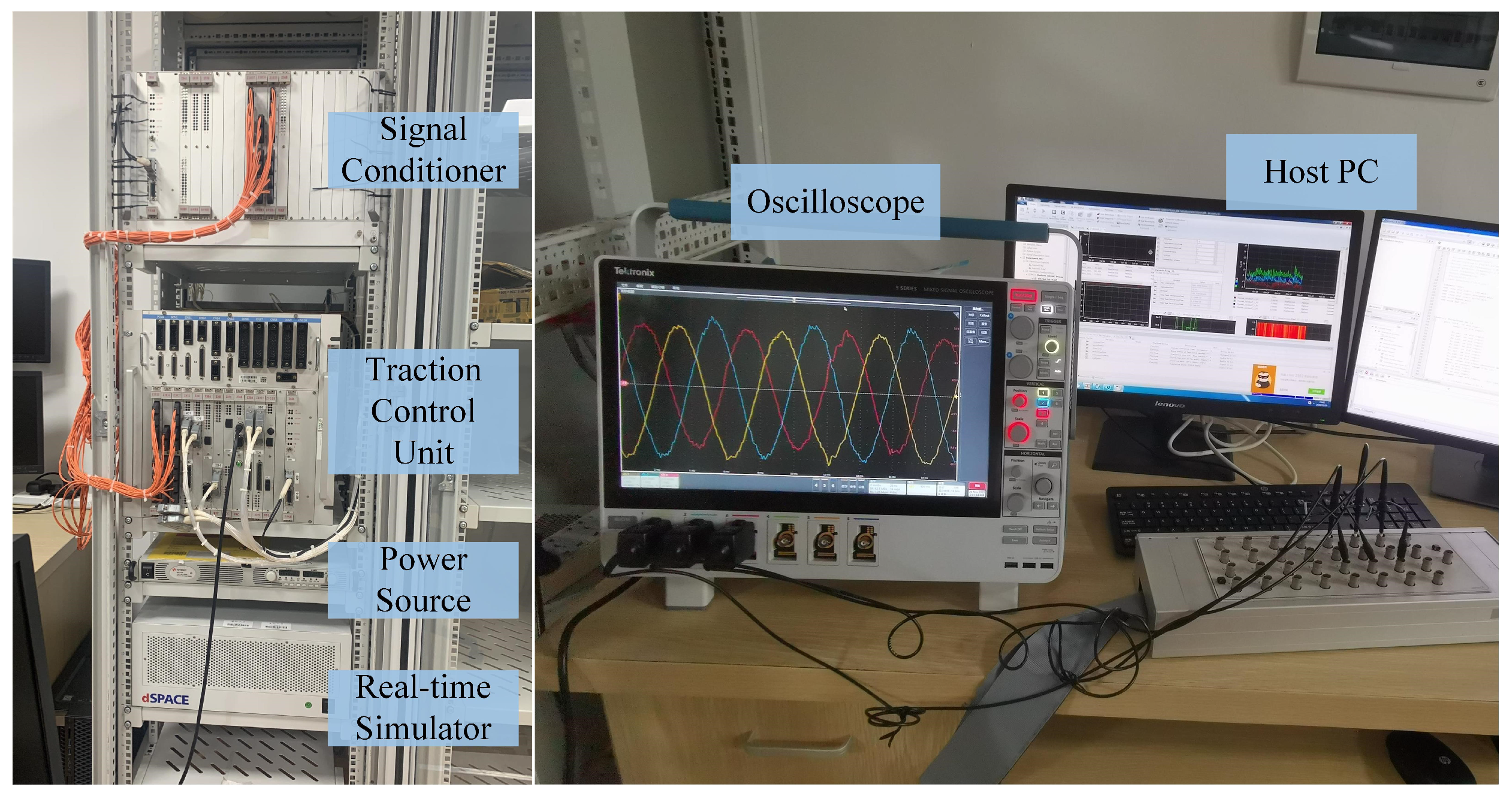
The proposed identification strategy in this paper is validated on the hardware-in-the-loop (HIL) platform. Figure 5 is the schematic diagram of the experimental platform [26]. The whole vehicle model of the train can be simulated through the real-time simulator from dSPACE GmbH in Paderborn, Germany. The parameters of the model used for experimental verification are shown in Table 1.
The time taken for the faulty wheelset to deteriorate from the early stage to the serious stage varies significantly under different friction conditions. In this section, the wheelset has the slipping fault under two distinct severity levels of friction conditions, and the parameters of FFCC-a and FFCC-b for the two different friction conditions are shown in Table 2. The NLLS-based identification strategy, MDIPF-based identification strategy, and the proposed identification strategy are validated under the different friction conditions. The detailed discussion is conducted on the goodness of fit and the identification time of the three distinct identification strategies.

4.2. Experimental Results

4.2.1. Case1

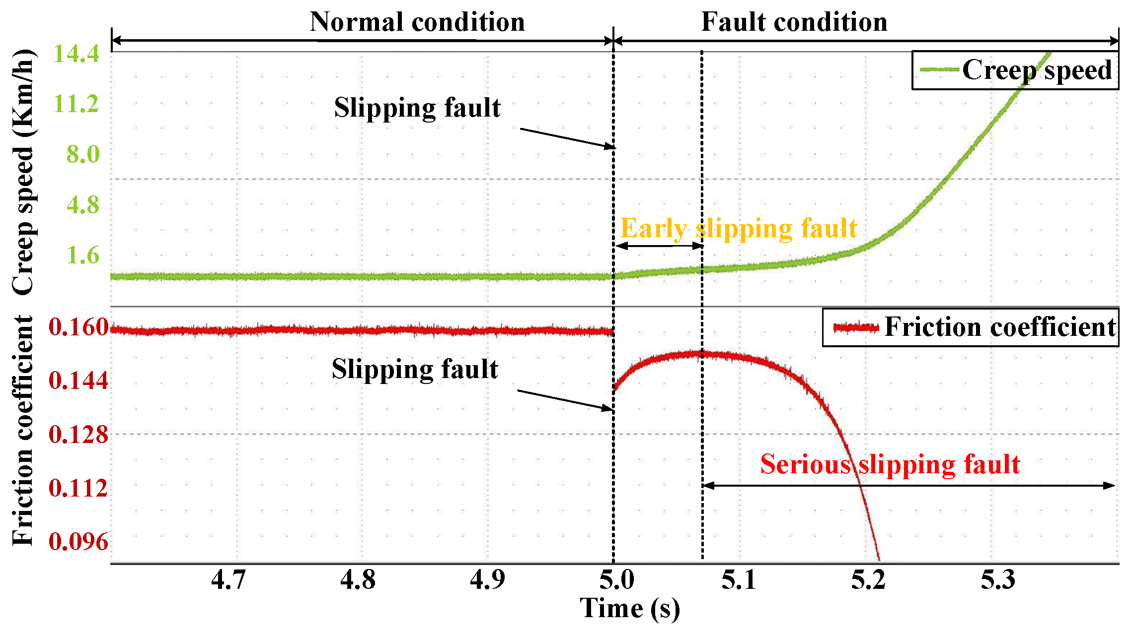
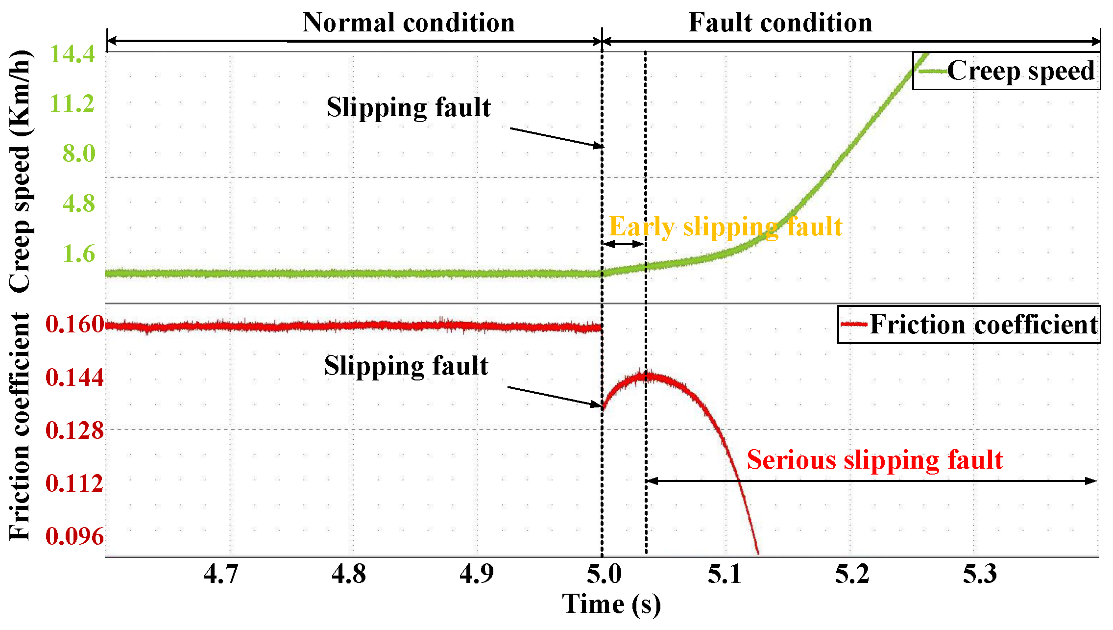
The slipping fault occurs in wheelset under under the friction condition of FFCC-a. Figure 6 shows the changes in the creep speed and friction coefficient of the faulty wheelset.
After the occurrence of the slipping fault, the wheelset initially enters the early slipping fault stage. As shown in Figure 6, during the early stage, the creep speed and the friction coefficient of the wheelset change slowly, indicating that the wheelset is in a relatively stable state. When the faulty wheelset deteriorates from the early stage to serious stage, the creep speed of the wheelset rapidly increases, and the friction coefficient of the wheelset sharply declines. The faulty wheelset enters a non-stable state.
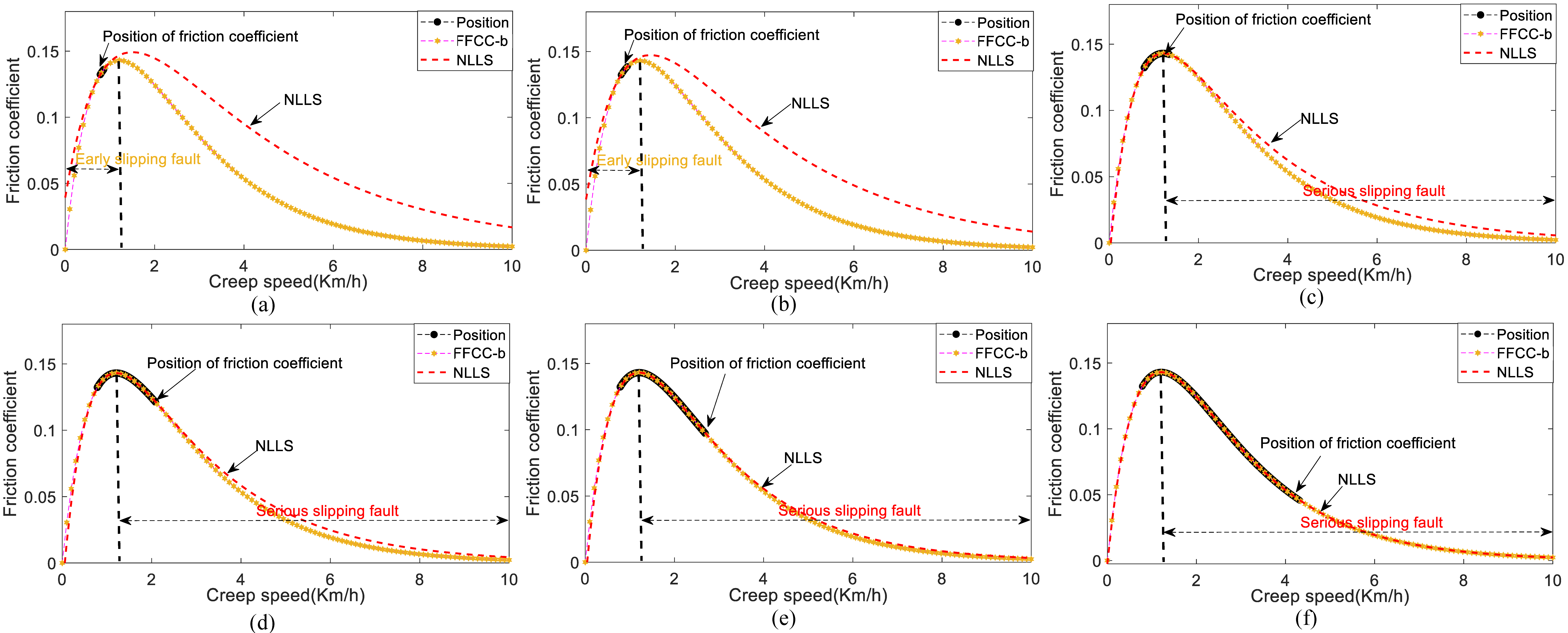
Figure 7 is the NLLS-based identification result of the FFCC-a. And Figure 7a–f correspond to the identification results obtained at 0.005 s, 0.01 s, 0.05 s, 0.1 s, 0.15 s, and 0.2 s after the occurrence of the slipping fault, respectively. From Figure 7a–c, it can be found that the NLLS-based identification result is unable to accurately identify FFCC-a during the early slipping fault stage. From Figure 7d–f, it is evident that the NLLS-based identification result shows significant improvement. Particularly, in Figure 7f, FFCC-a has been accurately identified for the most part. However, the faulty wheelset has entered the serious slipping fault stage.
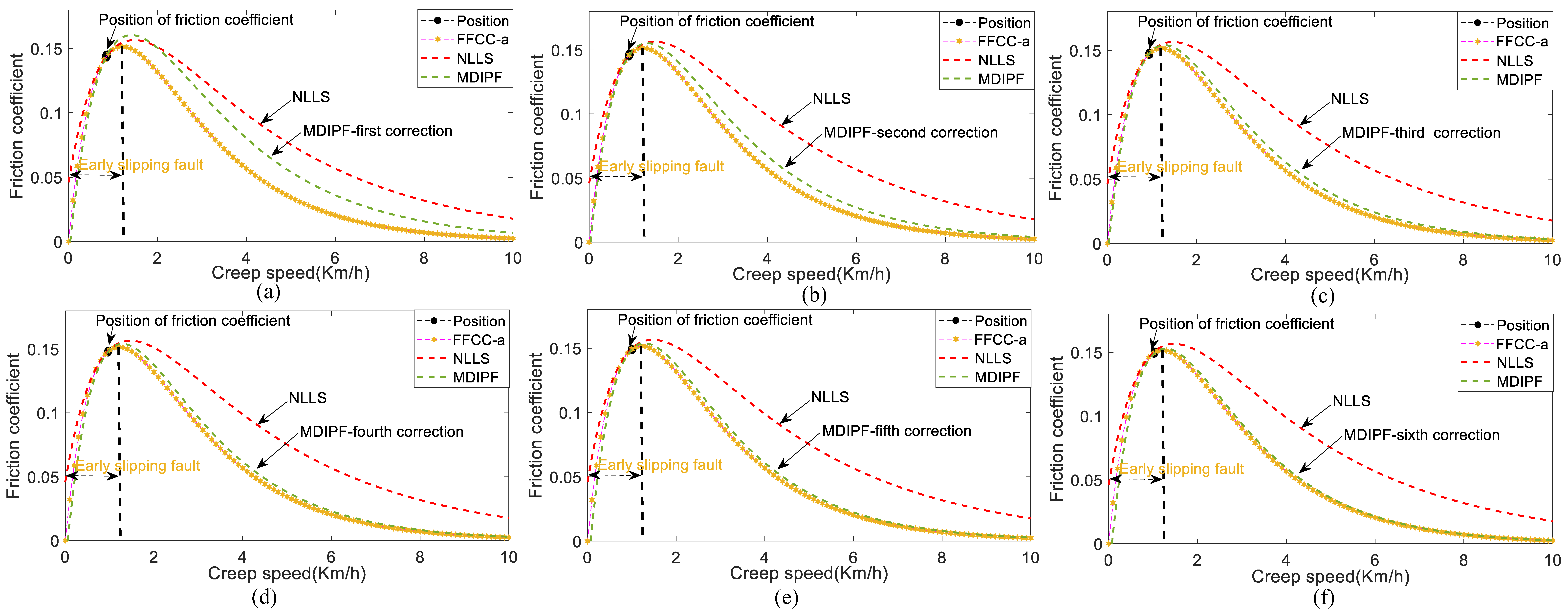
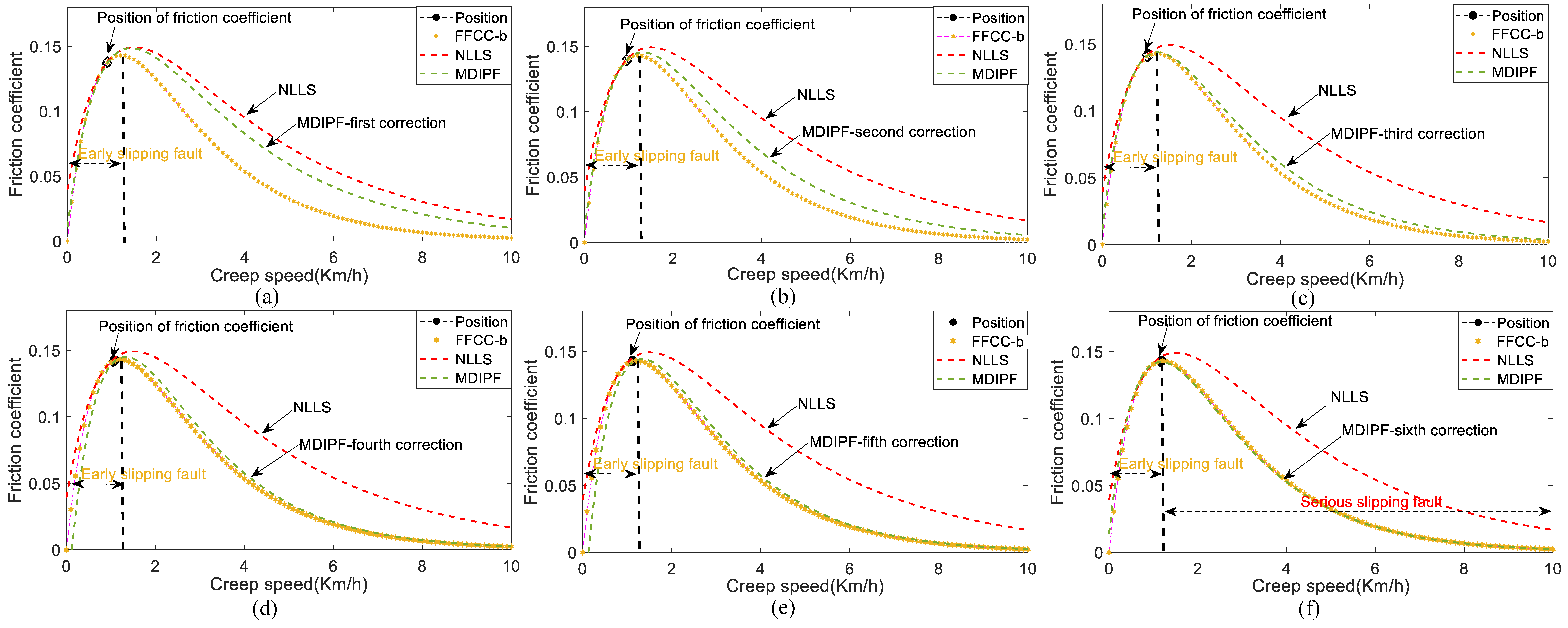
Figure 8 is the MDIPF-based identification result of the FFCC-a. And Figure 8a–f represent the results of the first correction, second correction, third correction, fourth correction, fifth correction, and sixth correction, respectively. Based on Figure 8, it can be observed that FFCC-a can be accurately identified after six corrections using the MDIPF-based identification strategy. Moreover, as shown in Figure 8f, the faulty wheelset is still in the early stage.
Figure 9 is the proposed strategy-based identification result of the FFCC-a. And Figure 9a–c represent the results of the first correction, second correction, and third correction, respectively. From Figure 9c, it can be observed that when FFCC-a is identified using the proposed strategy, the faulty wheelset remains in the early stage. And compared to MDIPF-based identification strategy, the proposed strategy-based identification requires only three corrections to achieve accurate identification of the FFCC-a.

4.2.2. Case2

As shown in Figure 10, in comparison to Case 1, the faulty wheelset experiences minimal time in the early stage and quickly deteriorates into the serious slipping fault under the friction conditions of FFCC-b.
Figure 11 is the NLLS-based identification result of the FFCC-b. And Figure 11a–f correspond to the identification results obtained at 0.005 s, 0.01 s, 0.05 s, 0.1 s, 0.12 s, and 0.15 s after the occurrence of the slipping fault, respectively. From Figure 11, it can be found that the faulty wheelset has already entered the serious slipping fault stage in Figure 11c. In Figure 11f, although the FFCC-b is accurately identified by the NLLS-based identification strategy, the creep speed of the has wheelset already increased to 4.8 km/h, and the friction coefficient of the wheelset has decreased to 0.045. The faulty wheelset is in an extremely unstable state, which can easily lead to a series of train accidents.
Figure 12 is the MDIPF-based identification result of the FFCC-b. And Figure 12a–f represent the results of the first correction, second correction, third correction, fourth correction, fifth correction, and sixth correction, respectively. From Figure 12, it can be observed that while the FFCC-b can be accurately identified by the MDIPF-based identification strategy, the faulty wheelset is on the verge of entering the serious slipping fault stage after the sixth correction.
Figure 13 is the proposed strategy-based identification result of the FFCC-b. And Figure 13a–c represent the results of the first correction, second correction, and third correction, respectively. Compared to the NLLS-based identification strategy and the MDIPF-based identification strategy, the proposed strategy remains capable of accurately identifying FFCC-b during the early slipping fault stage.

4.3. Discussion

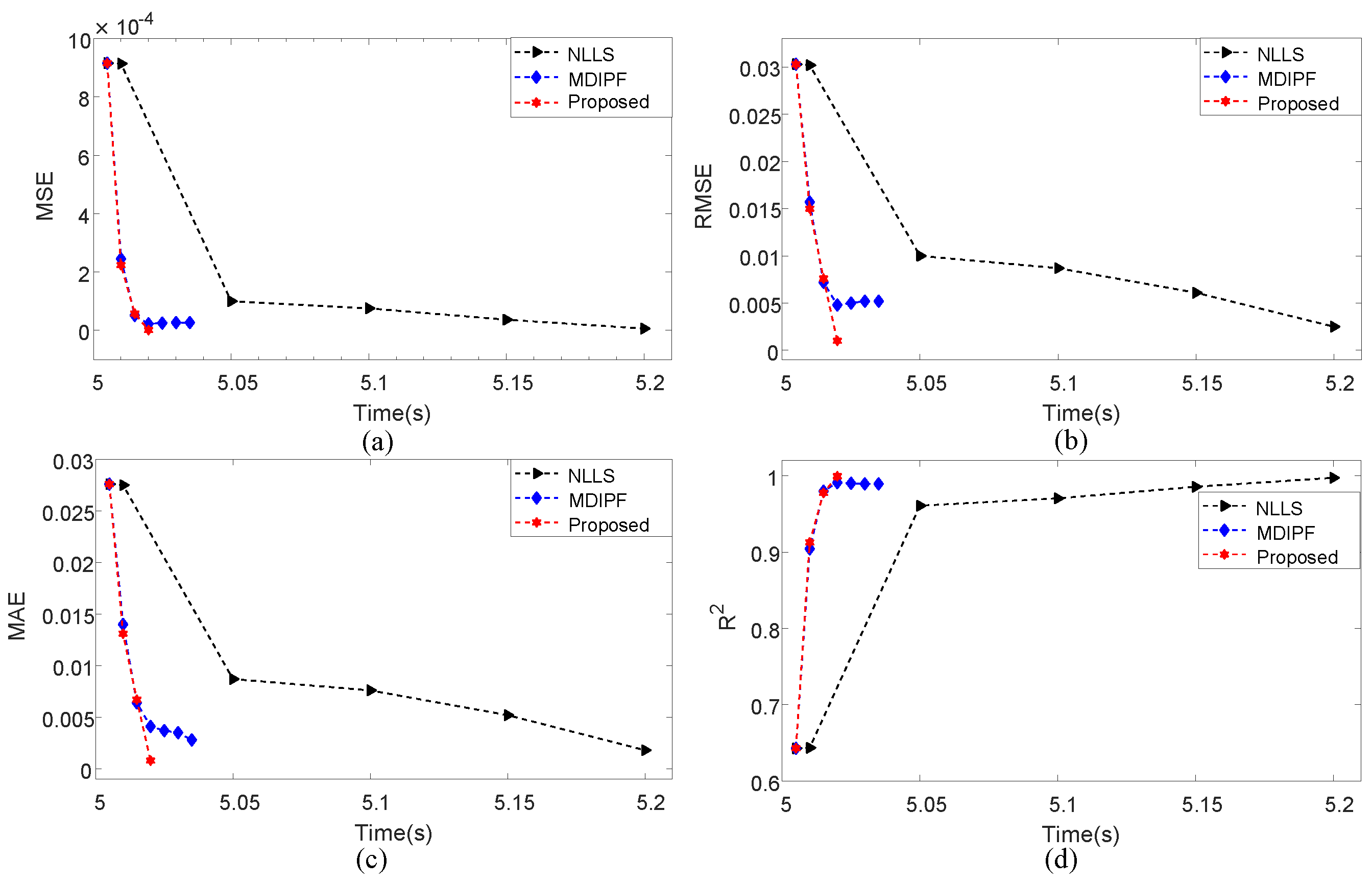
Figure 14 and Figure 15 are the comparative analysis of the goodness of fit for each identification of FFCC-a and FFCC-b. The goodness of fit for the three identification strategies is assessed using four indicators: Mean Square Error (MSE), Root Mean Square Error (RMSE), Mean Absolute Error (MAE), and R-square ( R 2 ).
The expressions of the MSE, RMSE, MAE, and R 2 are as follows:
M S E = 1 n κ = 1 n μ F a u _ κ M Q v s _ κ , λ ^ 0 c o r Q , λ ^ i c o r Q , τ ^ j c o r Q 2
R M S E = 1 n κ = 1 n μ F a u _ κ M Q v s _ κ , λ ^ 0 c o r Q , λ ^ i c o r Q , τ ^ j c o r Q 2
M A E = 1 n κ = 1 n μ F a u _ κ M Q v s _ κ , λ ^ 0 c o r Q , λ ^ i c o r Q , τ ^ j c o r Q
R 2 = 1 κ = 1 n μ F a u _ κ M Q v s _ κ , λ ^ 0 c o r Q , λ ^ i c o r Q , τ ^ j c o r Q 2 κ = 1 n μ F a u _ κ μ ¯ F a u 2
where μ F a u _ κ is the κ th friction coefficient calculated according to Equation (12) and μ ¯ F a u is the mean of all friction coefficient.
From Figure 14 and Figure 15, it can be seen that the NLLS-based identification strategy ultimately achieves a superior goodness of fit. However, this strategy exhibits a slow convergence rate, which can potentially cause the deterioration of the slipping fault into a serious slipping fault as the fault progresses. Furthermore, as shown in Figure 15, it can be observed that the MDIPF-based identification strategy exhibits a lack of rapid and stable convergence when identifying FFCC-b. This indicates that the MDIPF-based identification strategy is unable to achieve a prompt and accurate identification of the FFCC under various friction conditions. From Figure 14 and Figure 15, it can also be observed that in comparison to the NLLS-based identification strategy and the MDIPF-based identification strategy, the proposed strategy consistently achieves superior goodness of fit for the identification of both FFCC-a and FFCC-b in the shortest amount of time.
In the Table 3, the RT refers to the time it takes to identify the FFCC-a and FFCC-b relative to the time it takes for the early stage of the fault deterioration to progress to the serious stage of the fault. According to Table 3, the proposed identification strategy not only achieves accurate identification of FFCC-a and FFCC-b but also further reduces the RT of identification. Compared to the NLLS-based identification strategy and MDIPF-based identification strategy, the proposed strategy can ensure the accurate identification of FFCC-a and FFCC-b in the early stage of the fault.

5. Conclusions

At present, the identification of the FFCC faces a significant potential problem: the FFCC of varying severity struggles to achieve accurate identification before the early slipping fault deteriorates into a serious slipping fault. Hence, the dynamic-projection-integrated particle-filtering-based identification strategy of the FFCC for the train wheelset is proposed. First, an MDIPF-based parameters correction method is proposed. The MDIPF constructs an error particle state transition model, which takes into full consideration the intercorrelation among multi-dimensional parameters. Second, a DPD-based particle refinement method is proposed. The multi-dimensional edge particles of the FFCC are projected according to the new projection domain. Third, a multi-level evaluation-based identification method for the FFCC is proposed. Finally, the proposed identification strategy is validated on the experimental platform.
The significance of this paper is as follows: firstl, the MDIPF-based parameters correction method can effectively integrate inter-particle correlation to facilitate error fusion during the state transition process, which accelerates the correction speed of error parameters in the FFCC; secondly, the proposed DPD-based particle refinement method dynamically fine-tunes the particle projection domain, which effectively improves the convergence speed in identifying the FFCC; third, the proposed identification strategy can ensure the accurate identification of the FFCC under various friction conditions during the early stage of the faulty wheelset. In the future, we plan to conduct further research on the identification of the FFCC in a real test scenario with the inevitable constraints.

Author Contributions

Conceptualization, S.Y., C.Y. (Chao Yang) and T.P.; methodology, S.Y.; software, S.Y. and C.Y. (Chao Yang); validation, S.Y.; formal analysis, S.Y.; investigation, S.Y.; resources, T.P., C.Y. (Chunhua Yang), W.G. and L.L.; data curation, L.L.; writing—original draft preparation, S.Y.; writing—review and editing, S.Y. and T.P.; visualization, S.Y.; supervision, T.P., C.Y. (Chunhua Yang) and W.G.; project administration, T.P., C.Y. (Chunhua Yang) and L.L.; funding acquisition, T.P., C.Y. (Chunhua Yang), W.G. and L.L. All authors have read and agreed to the published version of the manuscript.

Funding

This work was supported, in part, by the National Key Research and Development Program of China under Grant 2022YFB4300504-3; by the National Natural Science Foundation of China under Grants 62233012, 62173350, and 62203474; by the Hunan Provincial Natural Science Foundation of China under Grant 2023JJ40777; and by the Key Laboratory of Energy Saving Control and Safety Monitoring for Rail Transportation under Grant 2017TP1002.

Data Availability Statement

The data presented in this study are available on request from the corresponding author.

Conflicts of Interest

Author Ling liu was employed by the company CRSC Research & Design Institute Group Co., Ltd. The remaining authors declare that the research was conducted in the absence of any commercial or financial relationships that could be construed as a potential conflict of interest.

Abbreviations

The following abbreviations and mathematical symbols are used in this paper:
Abbreviations
DPDdynamic projection domain
MDIPFmulti-dimensional integrated particle filtering
MLEmulti-level evaluation
HILhardware-in-the-loop
NFCCnormal friction characteristic curve
FFCCfault friction characteristic curve
NLLSNonlinear least squares
EPSTMerror particle state transition model
TCUtraction control unit
SCsignal conditioner
Nomenclature
w f a u speed of the faulty wheelset
r f a u radius of the faulty wheelset
v t train speed
v s creep speed
T W axle load of the faulty wheelset,
ggravitational acceleration
F f a u friction force
sgradient
HHessian matrix
A μ F a u state matrix
B μ F a u input matrix
C μ F a u output matrix
H μ F a u feedback gain matrix
λ 00 parameter of the NFCC
λ i 0 parameter of the NFCC
τ j 0 parameter of the NFCC
λ 0 parameter of the FFCC
λ i parameter of the FFCC
τ j parameter of the FFCC
h w F a u gain parameter of the speed
h T L F a u gain parameter of the load torque
J m rotation inertia of the wheelset motor
J d rotation inertia of the wheelset
η transmission efficiency
R g gearbox ratio

Appendix A

The expression of the relevant variables of the load torque observer is as follows:
A L F a u = 0 1 J m + J d / ( η R g 2 ) 0 0
B L F a u = 1 J m + J d / ( η R g 2 ) 0 0 0
C L F a u = 1 0
H L F a u = h w F a u h T L F a u T
x ^ L F a u k = w ^ F a u k T ^ L F a u k T
x ^ L F a u k + 1 = w ^ F a u k + 1 T ^ L F a u k + 1 T
u L F a u k = T e F a u k 0 T
where w ^ F a u k , w ^ F a u k + 1 are the estimated values of the wheelset speed at the kth and ( k + 1 ) th instants; T ^ L F a u k , T ^ L F a u k + 1 are the estimated values of the load torque at the kth and ( k + 1 ) th instants; T e F a u k is the electromagnetic torque at the kth instant; h w F a u is the gain parameter of the speed; h T L F a u is the gain parameter of the load torque; J m is the rotation inertia of the wheelset motor; J d is the rotation inertia of the wheelset; η is the transmission efficiency; and R g is the gearbox ratio.

Appendix B

The correlation coefficient is calculated as follows:
ι ξ i Q ξ i Q k 1 = N ξ i Q σ k 1 ξ i Q σ k 1 ξ i Q σ k 1 ξ i Q σ k 1 N ξ i Q σ k 1 2 ξ i Q σ k 1 2 N ξ i Q σ k 1 2 ξ i Q σ k 1 2
ι ξ i Q γ j Q k 1 = N ξ i Q σ k 1 γ j Q σ k 1 ξ i Q σ k 1 γ j Q σ k 1 N ξ i Q σ k 1 2 ξ i Q σ k 1 2 N γ j Q σ k 1 2 γ j Q σ k 1 2
ι γ j Q γ j Q k 1 = N γ j Q σ k 1 γ j Q σ k 1 γ j Q σ k 1 γ j Q σ k 1 N γ j Q σ k 1 2 γ j Q σ k 1 2 N γ j Q σ k 1 2 γ j Q σ k 1 2
where ξ i Q σ k 1 , γ j Q σ k 1 denote the σ th error particle corresponding to the parameters of the Qth corrected FFCC at the ( k 1 ) th instant, σ = 1 , , N .

References

  1. Peixer, M.A.; Montenegro, P.A.; Carvalho, H.; Ribeiro, D.; Bittencourt, T.N.; Calçada, R. Running safety evaluation of a train moving over a high-speed railway viaduct under different track conditions. Eng. Fail. Anal. 2021, 121, 105133. [Google Scholar] [CrossRef]
  2. Zhang, H.; Wei, X.; Guan, Q.; Zhang, W. Joint Maintenance Strategy Optimization for Railway Bogie Wheelset. Appl. Sci. 2022, 12, 6934. [Google Scholar] [CrossRef]
  3. Watanabe, A.; Kageyama, I.; Kuriyagawa, Y.; Haraguchi, T.; Kaneko, T.; Nishio, M. Study on the Influence of Environmental Conditions on Road Friction Characteristics. Lubricants 2023, 11, 277. [Google Scholar] [CrossRef]
  4. Do, M.T.; Cerezo, V.; Ropert, C. Questioning the approach to predict the evolution of tire/road friction with traffic from road surface texture. Surf. Topogr. Metrol. Prop. 2020, 8, 024004. [Google Scholar] [CrossRef]
  5. Xiao, G.; Wu, B.; Yao, L.; Shen, Q. The traction behaviour of high-speed train under low adhesion condition. Eng. Fail. Anal. 2022, 131, 105858. [Google Scholar] [CrossRef]
  6. Yin, S.; Peng, T.; Yang, C.; Yang, C.; Chen, Z.; Gui, W. Dynamic hybrid observer-based early slipping fault detection for high-speed train wheelsets. Control Eng. Pract. 2024, 142, 105736. [Google Scholar] [CrossRef]
  7. Sholevar, N.; Golroo, A.; Esfahani, S.R. Machine learning techniques for pavement condition evaluation. Autom. Constr. 2022, 136, 104190. [Google Scholar] [CrossRef]
  8. Zhang, C.; Zhang, Q.; He, J.; Liu, J. Review of research on key technologies for high-speed train wheel-rail condition monitoring. In Proceedings of the 8th International Symposium on Test Automation and Instrumentation, Online, 15 September 2021; pp. 257–264. [Google Scholar]
  9. Shrestha, S.; Wu, Q.; Spiryagin, M. Review of adhesion estimation approaches for rail vehicles. Int. J. Rail Transp. 2019, 7, 79–102. [Google Scholar] [CrossRef]
  10. Yuan, Z.; Wu, M.; Tian, C.; Zhou, J.; Chen, C. A review on the application of friction models in wheel-rail adhesion calculation. Urban Rail Transit. 2021, 7, 1–11. [Google Scholar] [CrossRef]
  11. Guo, H.; Zhao, X.; Liu, J.; Dai, Q.; Liu, H.; Chen, H. A fusion estimation of the peak tire–road friction coefficient based on road images and dynamic information. Mech. Syst. Signal Process. 2023, 189, 110029. [Google Scholar] [CrossRef]
  12. Ise, T.; Higuchi, M.; Suzuki, Y.; Tachiya, H. Measurement on friction coefficients of tire grounding surface in arbitrary directions under high-load. Exp. Mech. 2017, 57, 1383–1393. [Google Scholar] [CrossRef]
  13. Leng, B.; Jin, D.; Xiong, L.; Yang, X.; Yu, Z. Estimation of tire-road peak adhesion coefficient for intelligent electric vehicles based on camera and tire dynamics information fusion. Mech. Syst. Signal Process. 2021, 150, 107275. [Google Scholar] [CrossRef]
  14. Alonso, J.; López, J.M.; Pavón, I.; Recuero, M.; Asensio, C.; Arcas, G.; Bravo, A. On-board wet road surface identification using tyre/road noise and support vector machines. Appl. Acoust. 2014, 76, 407–415. [Google Scholar] [CrossRef]
  15. Feng, Y.; Chen, H.; Zhao, H.; Zhou, H. Road tire friction coefficient estimation for four wheel drive electric vehicle based on moving optimal estimation strategy. Mech. Syst. Signal Process. 2020, 139, 106416. [Google Scholar] [CrossRef]
  16. Paul, D.; Velenis, E.; Cao, D.; Dobo, T. Optimal μ-Estimation-Based regenerative braking strategy for an AWD HEV. IEEE Trans. Transp. Electrif. 2016, 3, 249–258. [Google Scholar] [CrossRef]
  17. Bian, M.; Chen, L.; Luo, Y.; Li, K. Research on maximum road adhesion coefficient estimation for distributed drive electric vehicle. In Proceedings of the 2013 International Conference on Mechanical and Automation Engineering, Jiujang, China, 21–23 July 2013; pp. 90–94. [Google Scholar]
  18. Wang, B.; Guan, H.; Lu, P.; Zhang, A. Road surface condition identification approach based on road characteristic value. J. Terramechan. 2014, 56, 103–117. [Google Scholar] [CrossRef]
  19. Guan, H.; Wang, B.; Lu, P.; Xu, L. Identification of maximum road friction coefficient and optimal slip ratio based on road type recognition. Chin. J. Mech. Eng. 2014, 27, 1018–1026. [Google Scholar] [CrossRef]
  20. Wang, Y.; Hu, J.; Wang, F.A.; Dong, H.; Yan, Y.; Ren, Y.; Zhou, C.; Yin, G. Tire road friction coefficient estimation: Review and research perspectives. Chin. J. Mech. Eng. 2022, 35, 6. [Google Scholar] [CrossRef]
  21. Niu, Y.; Jiang, X.; Meng, F.; Wang, R.; Ju, G.; Zhang, S.; Meng, Z. Techniques and methods for runway friction measurement: A review of state of the art. IEEE Trans. Instrum. Meas. 2021, 70, 9510717. [Google Scholar] [CrossRef]
  22. Zhang, X.; Xu, Y.; Pan, M.; Ren, F. A vehicle ABS adaptive sliding-mode control algorithm based on the vehicle velocity estimation and tyre/road friction coefficient estimations. Veh. Syst. Dyn. 2014, 52, 475–503. [Google Scholar] [CrossRef]
  23. Ricardo, D.; Esteves, A.; Jaime, S. A new linear parametrization for peak friction coefficient estimation in real time. In Proceedings of the 2010 IEEE Vehicle Power and Propulsion Conference, Lille, France, 1–3 September 2010; pp. 1–6. [Google Scholar]
  24. Bei, S.; Li, B.; Zhu, Y. Adhesion state estimation based on improved tire brush model. Adv. Mech. Eng. 2018, 10, 1687814017747706. [Google Scholar]
  25. Sharifzadeh, M.; Senatore, A.; Farnam, A.; Akbari, A.; Timpone, F. A real-time approach to robust identification of tyre–road friction characteristics on mixed-μ roads. Veh. Syst. Dyn. 2018, 57, 1338–1362. [Google Scholar] [CrossRef]
  26. Yang, C.; Peng, T.; Huang, X.; Fan, X.; Tao, H.; Yang, C.; Gui, W. Electrothermal Performance-Based FCS-MPC for Dynamic Thermal Balance Control of Traction Converters. IEEE Trans. Transp. Electrif. 2021, 8, 277–287. [Google Scholar] [CrossRef]
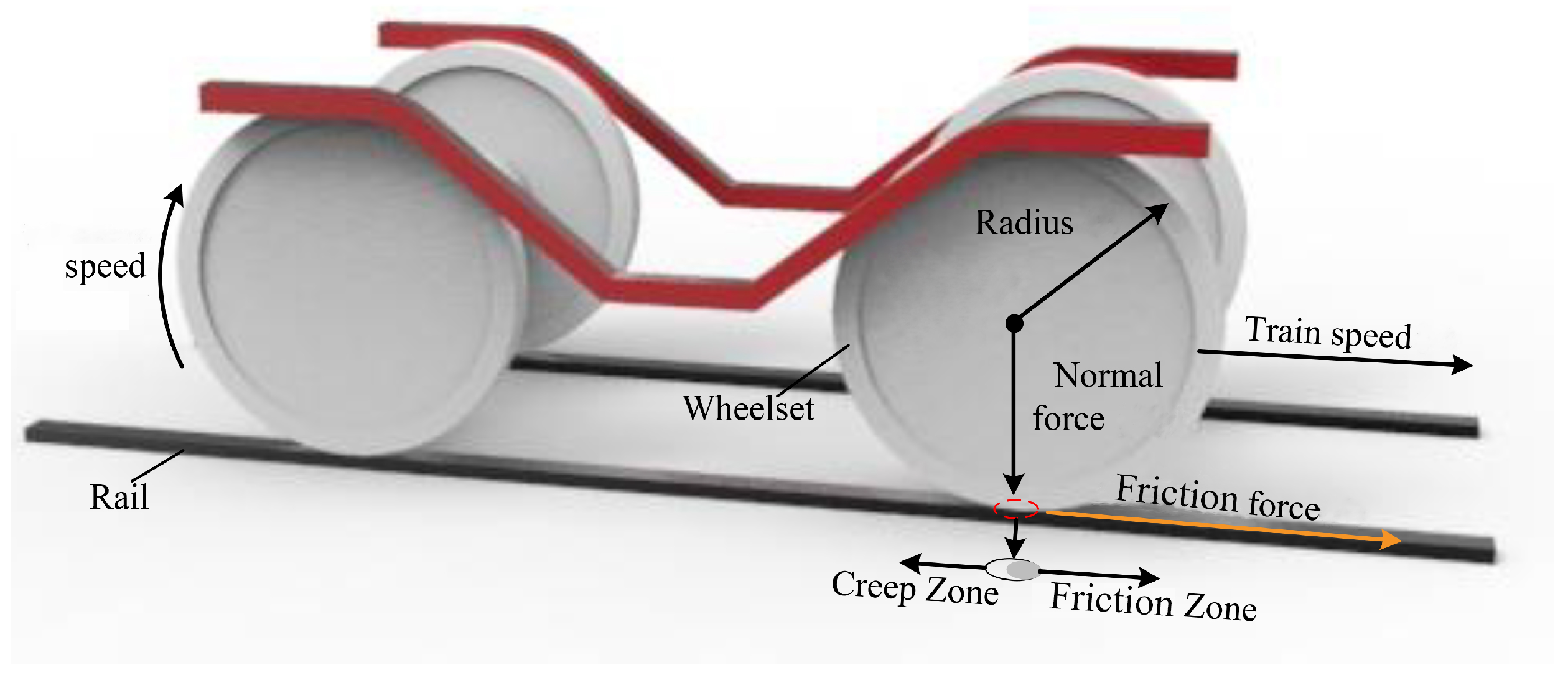
Figure 1. Schematic diagram of friction.
Lubricants 12 00038 g001
Figure 2. Schematic diagram of the NFCC and FFCC.
Lubricants 12 00038 g002
Figure 3. Schematic diagram of dynamic correction process of particles projection.
Lubricants 12 00038 g003
Figure 4. Scheme of dynamic-projection-integrated particle-filtering-based identification of friction characteristic curve on slipping fault.
Lubricants 12 00038 g004
Figure 5. Schematic diagram of the experimental platform.
Lubricants 12 00038 g005
Figure 6. The creep speed and friction coefficient of the faulty wheelset.
Lubricants 12 00038 g006
Figure 7. NLLS-based identification results of the FFCC-a.
Lubricants 12 00038 g007
Figure 8. MDIPF-based identification results of the FFCC-a.
Lubricants 12 00038 g008
Figure 9. The proposed strategy-based identification results of the FFCC-a.
Lubricants 12 00038 g009
Figure 10. The creep speed and friction coefficient of the faulty wheelset.
Lubricants 12 00038 g010
Figure 11. NLLS-based identification results of the FFCC-b.
Lubricants 12 00038 g011
Figure 12. MDIPF-based identification results of the FFCC-b.
Lubricants 12 00038 g012
Figure 13. The proposed strategy-based identification results of the FFCC-b.
Lubricants 12 00038 g013
Figure 14. Goodness of fit for the FFCC-a. (a)-MSE, (b)-RMSE, (c)-MAE, (d)- R 2 .
Lubricants 12 00038 g014
Figure 15. Goodness of fit for the FFCC-b. (a)-MSE, (b)-RMSE, (c)-MAE, (d)- R 2 .
Lubricants 12 00038 g015
Table 1. Parameters of the faulty wheelset.
SymbolTerminology of Parameters Value
T W axle load of the faulty wheelset 13.5  t
J m rotation inertia of the wheelset motor6 kg·m2
J d rotation inertia of the wheelset80 kg·m2
r f a u radius of the faulty wheelset 0.4375  m
Mweight of the train408 t
gacceleration of gravity9.8 m/s2
R g gearbox ratio 2.788
η transmission effciency 0.97
Lhalf of the center distance between two bogies19 m
L b half of the wheelbase 2.5  m
Zheight from the coupler to the ground 0.88  m
zheight of bogie 2.6  m
Table 2. Parameters of the FFCC-a and FFCC-b.
λ 0 λ 1 λ 2 τ 1 τ 2
Case1 (FFCC-a)−0.0050.585−0.580−0.525−1.100
Case2 (FFCC-b)−0.0020.478−0.476−0.505−1.180
Table 3. Performance comparisons.
NLLSMDIPFThe Proposed Strategy
MSE (FFCC-a/FFCC-b)6.3472  × 10 0.6 /1.4864  × 10 0.7 2.6921  × 10 0.5 /6.3028  × 10 0.6 1.0849  × 10 0.6 /6.1947  × 10 0.7
RMSE (FFCC-a/FFCC-b)2.5000  × 10 0.3 /3.8553  × 10 0.4 5.2000  × 10 0.3 /2.5000  × 10 0.3 1.0000  × 10 0.3 /7.8706  × 10 0.4
MAE (FFCC-a/FFCC-b)1.8000  × 10 0.3 /1.8151  × 10 0.4 2.8000  × 10 0.3 /1.2000  × 10 0.3 7.8984  × 10 0.4 /4.9837  × 10 0.4
R 2 (FFCC-a/FFCC-b)0.9975/0.99990.9895/0.99720.9996/0.9997
RT (FFAC-a/FFAC-b)310.6%/445.1%54.3%/103.9%31.1%/59.3%
Disclaimer/Publisher’s Note: The statements, opinions and data contained in all publications are solely those of the individual author(s) and contributor(s) and not of MDPI and/or the editor(s). MDPI and/or the editor(s) disclaim responsibility for any injury to people or property resulting from any ideas, methods, instructions or products referred to in the content.