Article

Testing the Effectiveness of Hybrid Milling and Surface Burnishing in Improving the Wear Resistance of Machine Parts Made of Structural Steel

Faculty of Mechanical Engineering and Mechatronics, West Pomeranian University of Technology in Szczecin, 70-310 Szczecin, Poland
*
Authors to whom correspondence should be addressed.
Lubricants 2024, 12(12), 458; https://doi.org/10.3390/lubricants12120458
Submission received: 15 November 2024 / Revised: 16 December 2024 / Accepted: 18 December 2024 / Published: 19 December 2024

Abstract

:
Due to the need to form a surface layer with specific operating properties, recent years have seen an increased interest in surface strengthening treatment, which aims to create a surface layer that improves the durability of parts. With a view to the economics of the machining process, it is common to combine shaping milling, characterised by high volumetric efficiency, with finishing burnishing, during which significant forces are applied. In the literature, one of the important limitations of such technological operations is the value of residual stresses, excessive values of which can lead to the flaking and falling off of surface fragments. In the present study, the authors put forward the research hypothesis that, in addition to stresses, the geometry of the machining roughness is also important and may contribute to faster tribological wear than stresses. It has been shown that what is important in hybrid machining is not so much the height of the resulting irregularities and the effectiveness of their levelling by burnishing, but the geometry of the irregularities. After milling, surfaces with small, regular irregularities with smooth peaks and shallow valleys were found to be the best in tribological tests. Such roughness can be plastically levelled out during burnishing. On the basis of the experimental studies carried out, it was shown that a higher burnishing force does not always lead to higher wear resistance.

1. Introduction

Proper shaping of the surface (by strengthening it) can extend the service life of machine parts and contribute significantly to their durability while reducing the amount of lubricants used. As a result of the need to form a surface layer with specific performance properties (see, for example, [1,2,3,4,5]), there has been an increased interest in recent years in surface strengthening treatment, which aims to produce a surface layer that improves the strength of a machine part. At the same time, in [6,7], it was shown which parameters of the geometrical texture of the surface are important in determining the properties of the surface layer and how their values change during wear. It should also be noted that wear is related to the surface microstructure of the machine part [8].
Tribological wear is generally an indirect cause of machine failure [9]. It can have various backgrounds and causes. In the operation of mechanical equipment, tribological wear processes include abrasive wear, adhesive wear, wear by oxidation, fatigue wear, chemical and electrochemical (corrosion) wear, cavitation wear, thermal wear and fretting [6]. The scope of contemporary scientific and technical research is most often concerned with determining the relationships associated with abrasive and fatigue wear processes and their impact on the loss of product functionality [10,11,12].
It can be assumed that surface wear is a type of wear in which local cohesion loss and associated material loss are caused by fatigue as a result of cyclic contact stresses in the surface layers of the parts to be joined. As a result of superimposed deformations in the surface layer, fatigue-induced surface microcracks form, subsequently progressing to macrocracks. The final result is the detachment of pieces of material from the core. Once the limit number of load cycles is exceeded and the fatigue limit is reached by the individual microvolumes of material in the surface layer, mass loss occurs.
Thus, strengthening the surface layer of mating parts (by introducing a favourable stress state) should contribute significantly to the mechanical resistance of parts to fatigue wear. One of the more popular strengthening treatments is burnishing, which is combined with machining operations such as milling [13,14,15], turning [16,17,18,19] or other methods of volumetric and ultrasonic machining [20,21,22,23].
The burnishing operation during the realisation of hybrid technological processes on CNC machine tools leads to an effective reduction in the height of roughness (through high efficiency and low cost). The degree of change in roughness after finishing burnishing in relation to the initial roughness after a machining operation (turning or milling) can be determined from the following relationship:
K = R o u g h n e s s   o f   t h e   m a c h i n e d   s u r f a c e   R o u g h n e s s   o f   t h e   b u r n i s h e d   s u r f a c e
where K is the technology effectiveness factor.
Depending on the way in which the burnishing is carried out and the type of material to be processed, calculated according to Equation (1), the technology effectiveness factor can take on a value of more than 5 [24,25] or even 10 [26,27].
The idea of effectiveness in levelling surface irregularities is confirmed by numerous published scientific results [28,29,30,31]. One of the more frequently emphasised limitations of burnishing is the so-called residual stresses [32,33,34]. Their maximum value should not be exceeded, as the strength of the material may be exceeded during the service life of the part (after the introduction of service stresses). As a result of exceeding the maximum strength of the material, there may be a local loss of material cohesion between the surface and the core in the form of microcracks (which often occur below the surface). The development of microcracks over an extended period of time results in the flaking and falling off of larger parts of the surface, contributing to accelerated wear of the parts.
Various studies have been carried out to analyse the burnishing process using experimental, numerical and analytical approaches. Rodríguez et al. [35] carried out an experimental and numerical approach to investigate the surface properties, hardness and residual stresses after the ball burnishing process. They found that the ball burnishing process significantly improves surface properties and residual stress values. El-Taweel and El-Axir [36] conducted an experimental study based on a response surface methodology to analyse the effects of burnishing speed, burnishing feed rate, number of passes and burnishing force on the surface roughness and hardness of turned parts. Analysis of variance showed that the burnishing force and feed rate had the greatest effect on surface roughness and hardness. Gharbi et al. [37] carried out an experimental study using the Taguchi experimental design to determine the effect of burnishing parameters on the surface properties of AISI 1010 flat surfaces using a multiball tool. The results obtained from the analysis of variance showed that the burnishing force has a significant effect on both hardness and surface roughness. Korzynski et al. [38] developed a hydrostatic pressure-loaded burnishing tool for machining chrome-coated surfaces. They found that coating operations induce tensile residual stresses on the specimens and reduce fatigue life by causing microcracks on the surface. However, after ball polishing, surface quality and fatigue life are improved by removing surface irregularities and reducing cracks. In addition, the residual tensile stress on the surface of the coated specimens is changed to compressive stress as a result of slip ball polishing. Avilés et al. [39] investigated the effect of a low plasticity ball-burning process on improving the fatigue strength of normalised AISI 1045 steel. Both untreated and blackened ball-burnished specimens were subjected to rotary bending fatigue tests up to 3.25 × 10⁶ cycles. It was shown that the fatigue strength of the ball-burnished specimens, compared to the untreated specimens, improves by approximately 21.25%. Travieso-Rodriguez et al. [40,41] also integrated longitudinal vibration with a burnishing tool to improve the surface characteristics of G10380 steel. They analysed the surface roughness, hardness and residual stresses of the burnished parts. The results showed that the application of vibration to the burnishing tool significantly improves the roughness of the burnished surface, but less robust results were observed in terms of specimen hardness and residual stresses. Revankar et al. [42,43] applied ball burnishing to the machining of titanium round bars. They investigated the surface roughness, hardness, wear resistance and residual stress of the specimens subjected to burnishing. They found that the use of ball burnishing significantly improves the respective properties compared to turned specimens.
It can be seen from the above observations that most of the research was carried out based on experimental studies. However, in order to better understand the mechanism of ball-crimping and extend its application, theoretical studies are very useful. In this case, few studies have been carried out to analyse the burnishing forces or the surface generation mechanism. Luo et al. [44] carried out an analytical study to predict the burnishing force. They used the elastic Hertz contact model to determine the coring depth threshold for elastic deformation. In turn, they obtained the values of the pressing depth for elastic-plastic and plastic deformations. The results obtained from their analytical model were in good agreement with the experimental results. Hiegemann et al. [45,46] developed a theoretical model to predict the surface roughness and pressure of the coated surface. They also used the Hertz contact theory with appropriate simplifications to include the effect of burnishing depth in the model. The results showed that the experimental results were consistent with the analytical approach. Korzynski [47] developed an analytical model based on micromechanical slip line theory to correlate the relationship between surface roughness and burnishing force. The model included the mechanical parameter of the material, the burnishing force, the number of surface roughness over a given length, the angle of surface roughness and the geometrical parameters of the burnishing process, such as the ball diameter. With the help of this model, the surface roughness of the specimen can be predicted after a one-time burnishing process.
Complementing the research presented above is our research described in this paper. It describes tribological tests carried out on surfaces that were characterised by a similar height of roughness. However, the surface irregularities were created under different technological conditions. The first case was the combination of fine (i.e., labour-intensive) milling with light surface burnishing, the result of which is shown in Figure 1a (as an example of an economically unsustainable operation). The second case was the combination of shaping milling with heavy surface burnishing, the result of which is shown in Figure 1b (as an example of an economically sustainable operation).
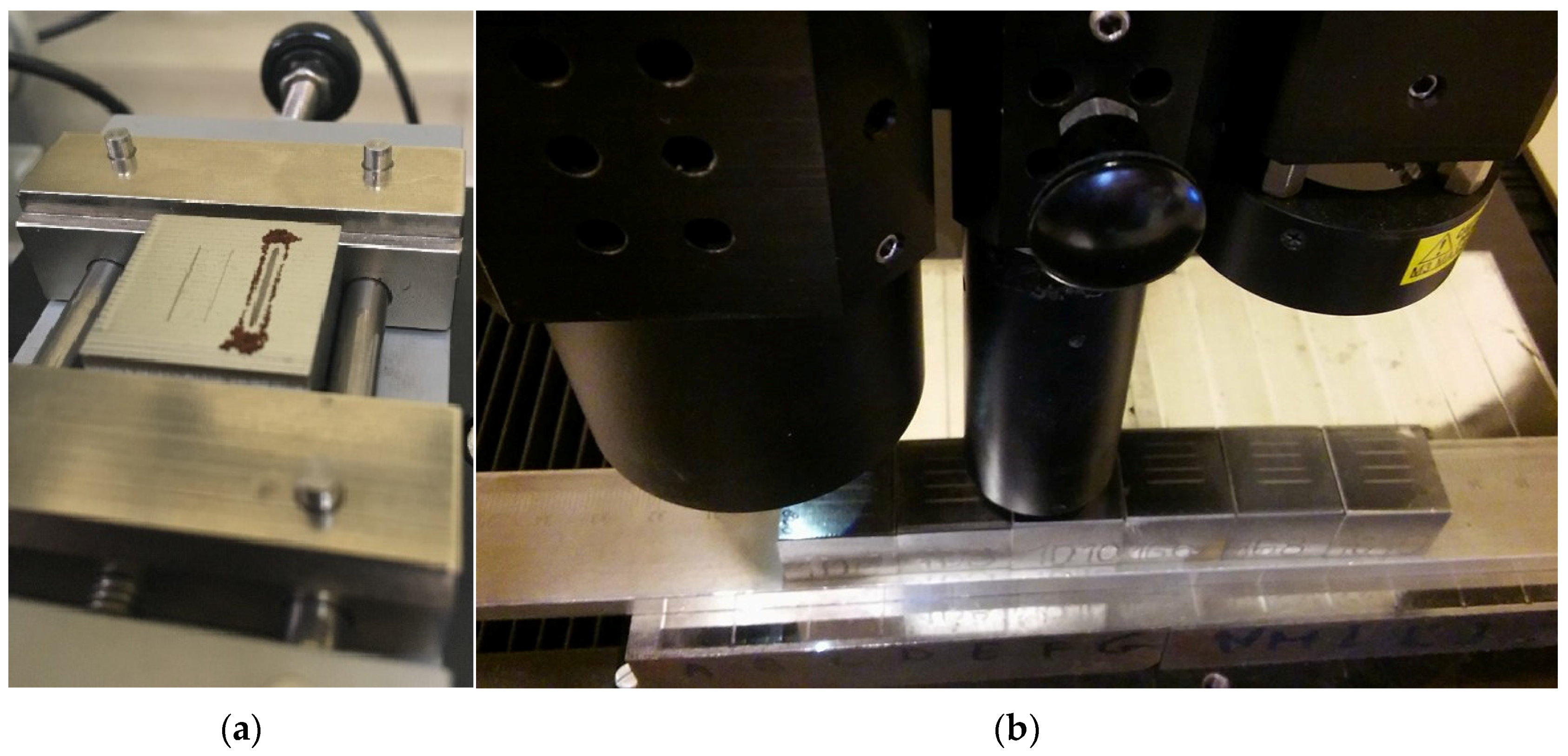
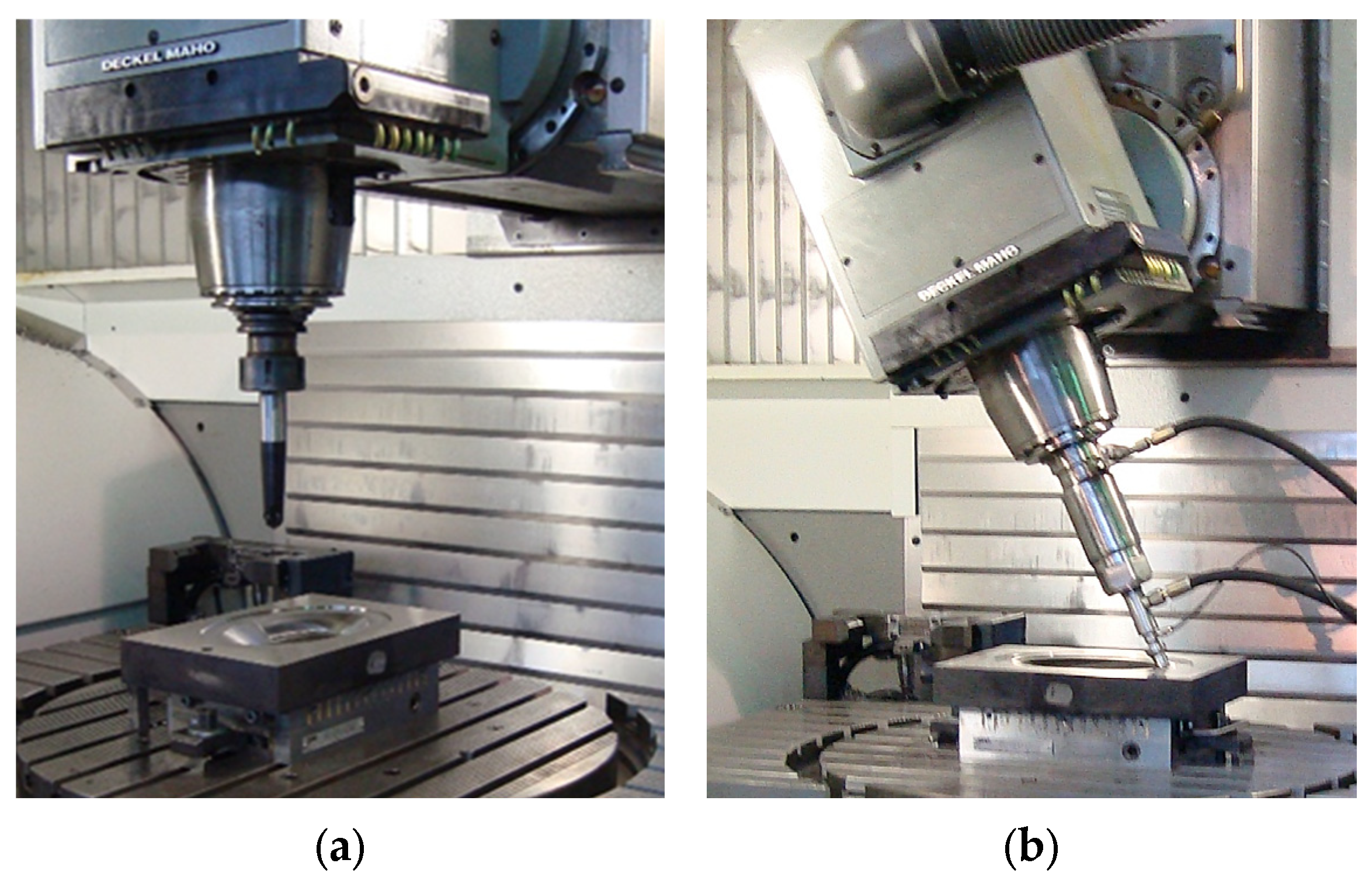
During the experiment that is the subject of this article, milling and burnishing operations of specimens were carried out on a single CNC machine tool (see Figure A1 in Appendix A), achieving a similar state of the geometrical texture of their surfaces under different process parameters. The aim of this experiment was to investigate how changes in the geometry of surface irregularities after milling and burnishing conditions contribute to changes in the tribological properties of product surfaces. The conclusions were based on an examination of the surface wear process.
In the literature related to the study of the state of the surface geometrical texture, one can find many works related to the modelling of the height of surface irregularities after the application of typical machining processes. The area of interest is usually models determining the values of indices such as Ra or Rz, which are most often used in technological documentation and technical drawings [48,49]. There is also a lot of work on modelling surface properties related to wettability [50,51,52], the ability of the surface to hold paint coatings [53,54,55] and ensuring adequate strength of adhesive joints [4,56,57].
The most commonly described models take into account the technological parameters of the cutting process for materials such as steel, cast iron or plastics. As mentioned in the Introduction, there is a lot of work on modelling the surface roughness after burnishing. In contrast, relatively little attention has been paid to the study of the functionality of surfaces obtained by hybrid manufacturing. This is generally due to the considerable difficulty of such studies, the degree of compilation of the process model itself and nevertheless the high demand for computing power. Therefore, this area is dominated by experimental work in which the influence of the technological parameters of the two treatments on the basic indices of roughness height, such as Ra (or Sa), Rz (or Sz) and the degree of isotropy, was most often determined [29,58].

2. Materials and Methods

The actual interaction of the friction surfaces of two solid bodies sliding against each other depends on the contact surfaces and the physical properties of the materials of the parts rubbing against each other. The surfaces of all solids, especially machine parts, have a certain state of roughness. The surface geometry of machine parts is shaped by the machining process. The machined surface has irregularities, resulting from errors in shape, position, waviness and roughness, which characterise the surface geometry obtained during machining. The specimens to be tested were prepared in such a way as to take into account all the effects that usually accompany production under industrial conditions.

2.1. Preparation of Specimens for Testing

Six specimens of C45 steel with a hardness of 189HV30 ± 6 and dimensions of 20 mm × 20 mm × 20 mm were used for the tests. A Mitsubishi SRFT10 finger milling cutter (Mitsubishi Materials Corp, Chiyoda-Ku, Tokyo, Japan) with a 5 mm radius VP15TF round insert was used for shaping milling. Roughing of the specimens and shaping milling were carried out on a MIKRON VCE 500 machining centre (Haas Automation, Inc., Oxnard, CA, USA) at a cutting speed of vc = 80 m/min and a depth of cut of ap = 0.3 mm (see Figure 2). After machining, the machine was rearmed for burnishing, which was carried out using a hydrostatic head powered by a hydraulic unit [59] with a 10 mm diameter spherical working tip made of Al2O3 ceramic material.
An emulsion from Statoil (Statoil, Stavanger, Norway), commercially named ToolWay, with a concentration of 12%, was used as the machining fluid and the hydraulic fluid to feed the hydrostatic head. The burnishing force was set according to the values adopted in the experimental plan shown in Table 1.
In the experimental study, three specimens were prepared on which one measurement each was taken. A normal distribution was adopted for the obtained Rx values, for which the uncertainty expansion factor k = 2 (covering 95% of cases around the mean value). The value of the standard deviation S from the specimens (with 3 measurements) was determined from the spread of the received measurement values URx = 2S. Table 1 also summarises the results of profile measurements taken directly on the machine tool according to EN ISO 21920 [60,61,62].
The value of the burnishing force during machining was monitored using a piezoelectric force gauge and a Kistler 5019 multichannel charge amplifier (Kistler Instrumente AG, Winterthur, Switzerland) so that its variation did not exceed ±5% of the nominal value. During the burnishing process, in addition to the burnishing force Fb, the value of the transverse feed rate for milling fm was changed in steps. The experimental plan was carried out at a constant burnishing speed of 8 m/min. When switching the machine between milling and burnishing operations, reference profile roughness measurements were taken over a length of lt = 4.8 mm. The measurements were taken using a HOMMEL ETAMIC T1000 portable profilometer (HOMMEL ETAMIC, Villingen-Schwenningen, Germany) equipped with a TKU 300/600 inductive sensor. Three measurements were taken each time, while Table 1 shows the average values from the results obtained.
Measurements of the values of the profile roughness parameters were taken immediately after the finishing burnishing operation. Preliminary surface tests showed a roughness reduction of approximately 20% to as much as 50% of the roughness height values obtained after milling.
Surface hardness measurements were performed with a Vickers indenter (LV700AT, Leco, St. Joseph, MI, USA) at a load of 1 kg.
Precise measurements of the spatial state of the geometrical texture after milling and burnishing, together with an analysis of the tribological test traces, were developed in the next part of this study according to the experimental plan.

2.2. Shaping the Surface Geometrical Texture

To measure the spatial state of the surface geometrical texture, an Altisurf A520 multi-sensor measurement system (Altimet, Thonon-les-Bains, France) was used, which was equipped with a MPLS (Multi Point Line Sensor) confocal white light sensor with an operating range of up to 400 μm and a resolution in the optical axis of the instrument of 8 nm. During one measurement pass, 180 profiles were recorded on a selected section of the surface with a width of 1.6 mm.
A representative section of the surface bounded by dimensions of 4.0 mm × 4.0 mm was taken in this study. Digital processing of the recorded point cloud and determination of selected values of the surface geometrical texture indices were carried out using the MCubeMAP 8.1 software (Mitutoyo, Kanagawa, Japan).
The following set of indices was chosen to characterise the changes occurring on the surface after burnishing, and in subsequent tests of the resistance of burnished surfaces to tribological wear [63,64,65,66]:
  • Surface roughness height indices such as Sa (arithmetic mean surface height), Sz (maximum surface height), Sp (maximum surface peak height) and Sv (maximum surface valley depth);
  • Indices based on changes in the Abbott–Fireston curve such as Vmp (surface material peak volume), Vmc (surface material core volume), Vvc (surface void core volume) and Vvv (surface void valley volume).

2.3. Surface Wear Tests

Four independent surface wear tests were performed on each specimen (four independent wear tracks—see Figure 3a). A TRN S/N 18–324 Pin-on-Disk Tribometer (CSM Instruments, Peseux, Switzerland) was used to test the degree of surface wear in accordance with ASTM G99 [67,68]. Between successive series of tribological tests, the ball was changed and the surfaces of the specimens were cleaned in acetone using an ultrasonic cleaner. The tests were conducted at an air temperature of 22–24 °C and a relative humidity of 48–50%. A 6 mm diameter alumina ball loaded with a force of 1 N was used as a counter probe. A reciprocating motion with a stroke of 8 mm was used. The maximum linear velocity during testing was 30 mm/s (corresponding to a frequency of 3.75 Hz). The specimens were positioned during the test so that the direction of the wear tracks formed was parallel to the surface texture directionality left by the burnishing tool. The degree of surface wear was determined by the friction path realised, which was, respectively, 200, 400, 600 and 800 m. During all tests, the contact between the surface of the specimen and the ball was not interrupted. Only after all tests had been completed in accordance with the adopted experimental plan were the degree of wear and microhardness evaluated. The degree of wear was also determined in relation to the reference surface not subjected to the tribological test.
The assessment of surface wear (see Figure 3b) was carried out on the basis of the developed methodology for investigating changes in the geometric texture of the surface with the previously developed methodology—described in Section 2.2. The test section covered an area of 10 mm × 10 mm, from which four separate sections of 2 mm × 4 mm were then extracted with a single wear track.
The surface layers were examined using an FE-SEM SU-70 (Field Emission Scanning Electron Microscopy) microscope (Hitachi, Naka, Japan). The specimens for microscopic examination, after mechanical cutting, were mounted in conductive resin (Polyfast, Struers, Ballerup, Denmark) and mechanically ground and polished using a diamond and alumina suspension. The microstructures were chemically revealed using an etchant containing 1 cm3 of nitric acid and 100 cm3 of ethanol.

3. Results and Discussion

3.1. Measurements of Surface Parameters

Examples of surfaces after the complete hybrid machining operation are shown in Figure 4 and Figure 5.
The average results of the selected geometric texture parameters including the crack (on the corresponding friction path) are shown in Table 2.
Hardness measurements showed a significant increase in surface hardness after burnishing compared to the reference surface hardness after the milling process—see Table 3.
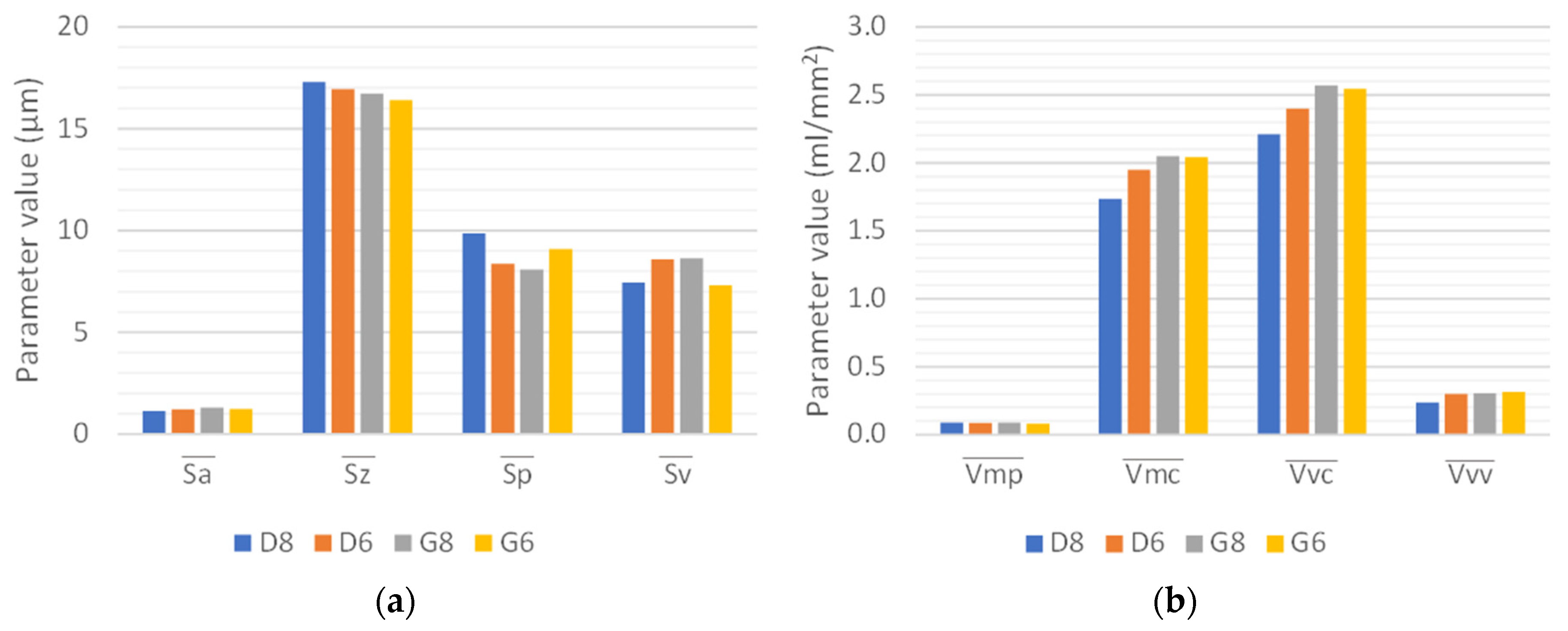
The reference surfaces in all cases were characterised by similar indicator values in both groups. The differences in the recorded parameter values in this case were within the natural range of variation of ±5% of the mean value of the selected index (Figure 6).

3.2. Studies of Surface Changes After Milling and Burnishing

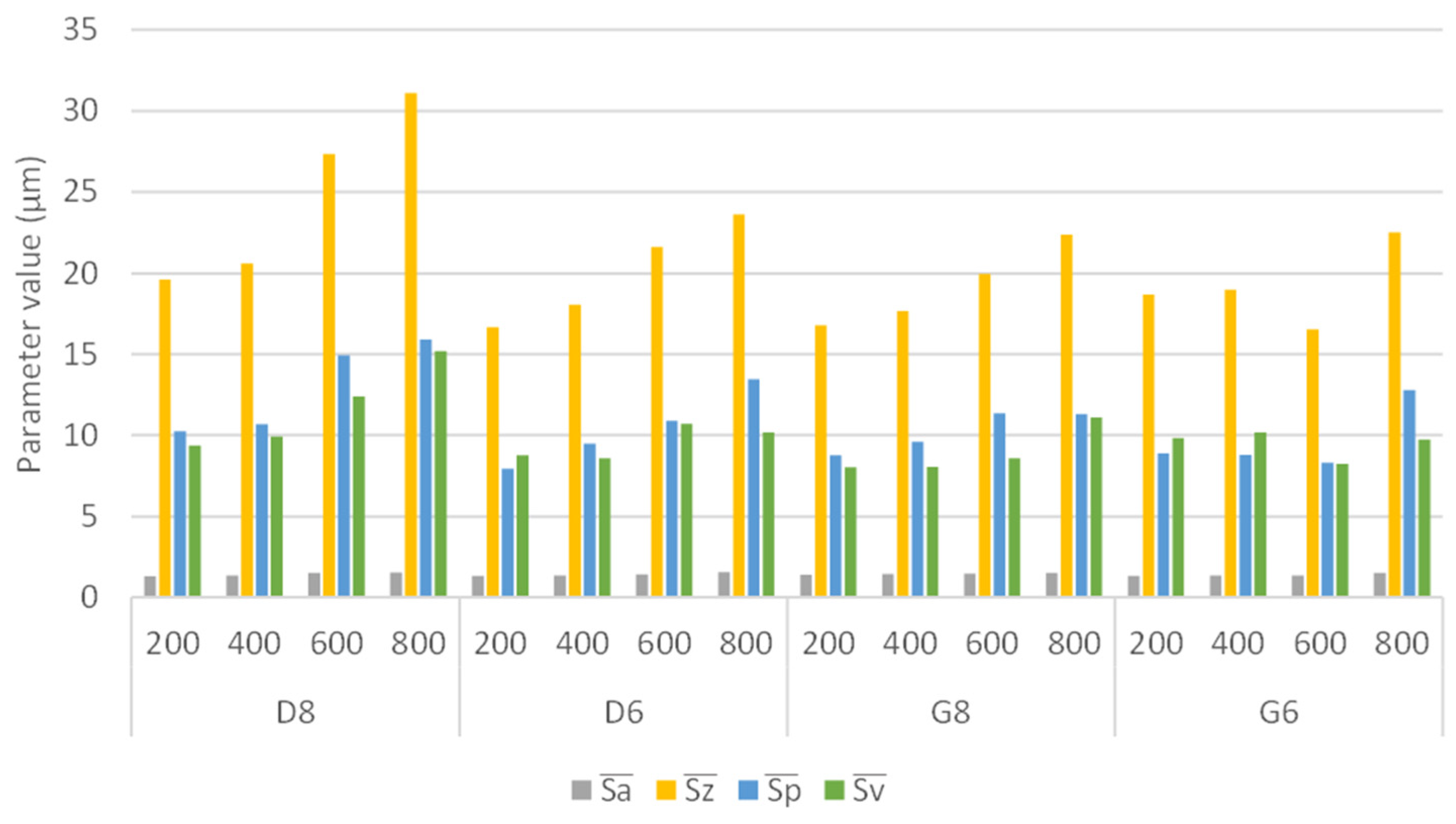
The wear tracks formed on the surfaces during the tribological tests resulted in a gradual increase in the height values of the surface geometrical texture indices as the friction path increased (Figure 7). It should be noted that the surfaces of specimens D8 and D6 burnished at a feed rate of fm = 0.4 mm were not as plastically strengthened as those of specimens G8 and G6 burnished at a feed rate of fm = 0.7 mm. When producing the surface of type D specimens, there was a sixfold reduction in the height of surface irregularities compared to a twofold reduction in the height of irregularities for type G specimens.
The easier and faster formation of wear tracks on the surface of specimens with a higher compression is to be explained by the separation of the harder, more plastically processed high roughness peaks (as illustrated by the greater changes in the values of the Sp indices in relation to the variations in the values of the Sv indices). The introduction of high stresses in the surface layer results in an increase in its hardness at the expense of a loss of its elastic properties. The particles falling off of the hardened surface during tribological tests acted as an additional abrasive contributing to faster surface erosion.
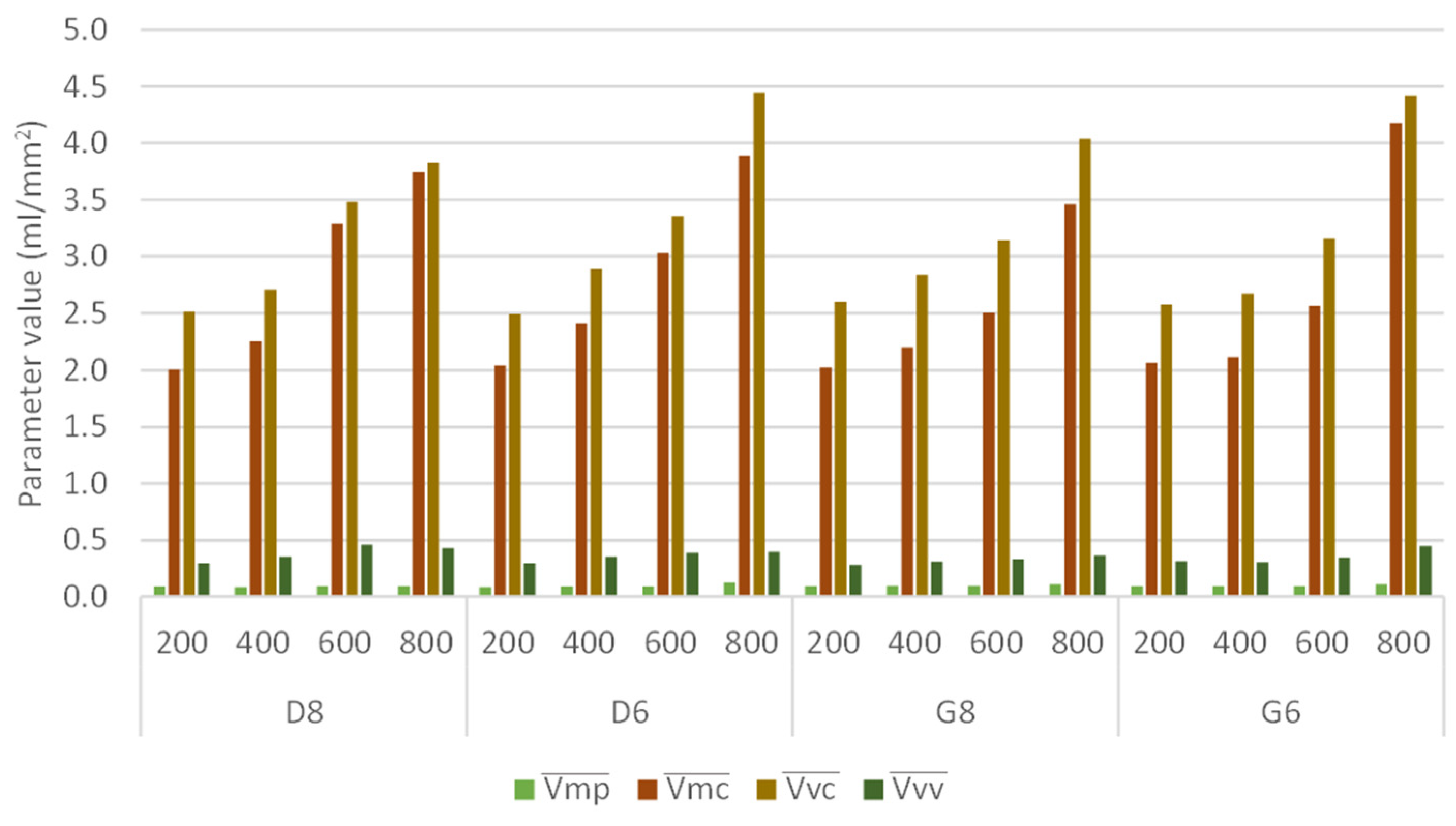
The changes in functional indices related to peak volume, core volume and surface valley volume during tribological testing are proportional to the realised friction path (Figure 8). This means that, in a similar surface image, the emerging wear track starts to dominate the tested surface section. Hence, the focus of the remainder of this study is on investigating the geometry of the wear track. Its width and depth, depending on the technological machining parameters, can be a better index of the resistance of the surface to abrasive wear.

3.3. Determination of Surface Wear

A cross-section of the surface that passed through all the wear tracks on a given specimen was selected for wear analysis (Figure 9a). Scans of the 11 mm × 8 mm surface were taken according to the previously presented methodology for measuring the surface geometrical texture. Using an automatic procedure in the MCubeMAP 8.1 software, the scratches were extracted. Their width, depth and surface area were then determined (Figure 9b).
The average values of the dimensions characterising the geometry of the wear tracks are shown in Table 4. The observations initially made on the topographic images and the conclusions drawn from the analysis of changes in selected indices of the surface geometrical texture were confirmed when analysing the geometry and surface area of the wear tracks formed in the tribological test (Figure 9).
In order that the degree of wear (DOW) could be determined, the values for wear track width, depth and area were normalised according to the following relationship:
N o r m ( x ) = x i x m i n x m a x x m i n
where x stands for the values of width W, depth D and area A, respectively.
The sum of the normalised values was determined as follows:
S u m ( W D A ) = N o r m ( W ) + N o r m ( D ) + N o r m ( A )
A situation in which a wear track with the maximum values of width, depth and area would have been observed during the experimental tests would have given a value of S u m ( W D A ) = 3 . Such a situation would have to be considered the maximum degree of wear. However, such a situation did not occur during the experimental tests. Therefore, the following relationship was used to determine the actual degree of wear:
D O W = S u m W D A i S u m W D A m i n 3
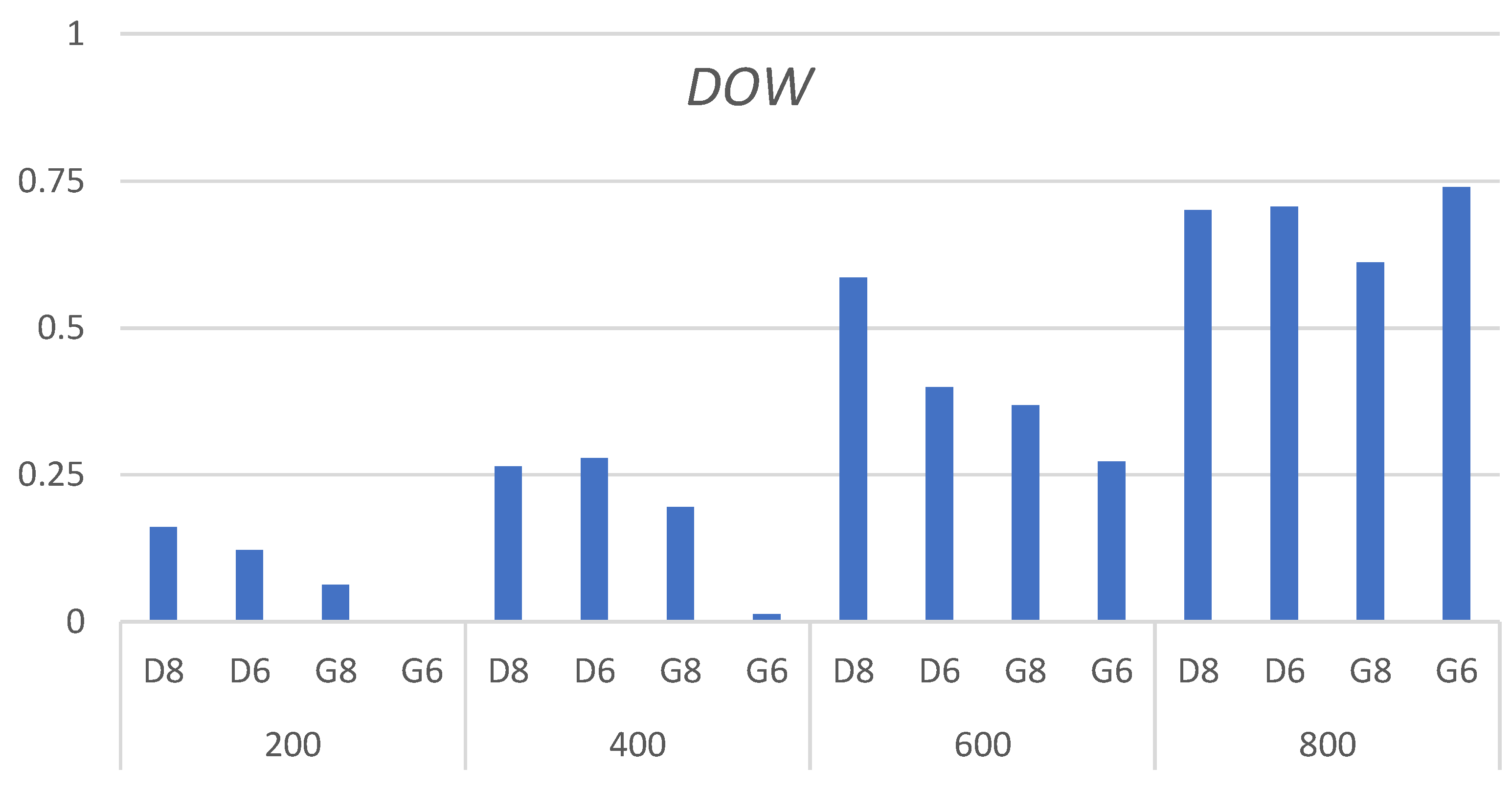
The resulting DOW values range from 0 to 1. They are summarised in Table 4, while Figure 10 shows the changes in DOW in graphical form.
On the basis of the analysis carried out of the determined degree of wear, initial observations of changes in the state of the geometrical texture of the surface can be confirmed. The wear tracks created as a result of the tribological test in the initial phase change this state only slightly. It is only when the friction path of 400 m is exceeded on the surface of specimens machined at fm = 0.4 mm and when the friction path of 600 m is exceeded on the surface of specimens machined at fm = 0.7 mm that the actual degree of surface wear exceeding the value of 0.25 is observed.
At both milling feeds fm = 0.4 mm and fm = 0.7 mm and in the full range of the applied burnishing force Fb, a significant degree of wear occurred after a friction path of 800 m was exceeded. The geometry of the wear tracks and their surface area led to the determination of a wear degree of 0.75. In this case, the deep crack was the dominant element in the observed spatial geometrical state of the surface. In most cases, the surfaces of the specimens burnished with Fb = 200 N wore more slowly compared to those burnished with Fb = 600 N. These surfaces also did not have such strongly rolled sharp peaks of unevenness. In the course of the experimental tests, no technological parameter association was obtained for which an actual wear rate above 0.9 would have been observed during tribological tests.
The most favourable properties were obtained for specimens with a surface milled at a feed rate of fm = 0.7 mm and burnished with a force of Fb = 200 N. This was a combination of high-performance burnishing with low force values. This is a treatment suitable, for example, for the spindle bearings of modern CNC machine tools. The prerequisite for obtaining a good surface finish is the combination of shaping milling conditions that produce regular irregularities with relatively smooth peaks and shallow valleys. Such irregularities during shaping can be reduced in the range of 50% of the initial Sa or Sz values (obtained after milling).
Experimental studies have shown that a higher burnishing force (inducing higher burnishing stresses) does not always lead to a higher wear resistance of the surface. Rather, high peaks of unevenness form in the surface, which break away and cause accelerated erosion of the surface. This mechanism is currently being investigated and it is planned to publish information on this subject in a separate article. In confirmation of this mechanism, an SEM image of specimen D8, which was one of the less resistant during the experimental tests, is included in Figure 11b. Such observations were not made for specimens showing high wear resistance (see Figure 11a).

4. Conclusions

On the basis of the conducted literature review and the realised experimental research, the following cognitive and utilitarian conclusions can be drawn for practical applications:
  • In addition to the value of the burnishing force, the state of the surface geometrical texture after milling has a significant influence on the end result of hybrid manufacturing;
  • In hybrid machining operations, it is not so much the height of the resulting irregularities and the effectiveness of their levelling by burnishing that is important, but the geometry of the irregularities. After milling, surfaces with small, regular irregularities with smooth peaks and shallow valleys were found to be the best in tribological tests. Such roughness can be plastically levelled out during burnishing. Rolled peaks that do not connect with the surface core should be avoided;
  • The realisation of high-performance hybrid manufacturing (by milling and burnishing), in which irregularities of considerable heights are burnished at significant force values (often above 1 kN), can lead to good smoothness and reflectivity on the surface (i.e., low roughness). However, locally high surface consolidation at shallow depths does not necessarily lead to an increase in the resistance of the surface to abrasive wear. It is better to take care of the efficiency of the surface burnishing procedure by using a higher feed rate and a ball in the tip of the burnisher with a larger diameter;
  • Experimental studies have shown that a higher burnishing force (inducing higher burnishing stresses) does not always lead to a higher wear resistance of the surface. Rather, high peaks of unevenness form in the surface, which break away and cause accelerated erosion of the surface.
  • The observed effects of the favourable tribological properties at low burnishing forces require further investigation. The present study should be regarded as preliminary research, and the developed methodology for determining the actual degree of surface wear should be applied to a wider range of experimental studies. The residual stresses obtained during surface burnishing need to be better understood, and their value may be a better correlation factor between technological processing parameters and the increase in the resistance of the surface to tribological wear. Numerical simulation models can be particularly helpful for their assessment.

Author Contributions

Conceptualisation, J.G. and D.G.; methodology, D.G., J.G. and P.K.; software, D.G.; validation, D.G., J.G. and P.K.; formal analysis, D.G. and R.G.; investigation, D.G., J.G. and P.K.; resources, J.G.; data curation, J.G. and D.G.; writing—original draft preparation, D.G.; writing—review and editing, D.G., R.G. and P.K.; visualisation, D.G., R.G. and P.K.; supervision, D.G. and R.G.; project administration, R.G.; funding acquisition, R.G. All authors have read and agreed to the published version of the manuscript.

Funding

This research received no external funding.

Data Availability Statement

Data are available upon request from the corresponding authors.

Conflicts of Interest

The authors declare no conflicts of interest.

Appendix A. Hybrid Manufacturing

In order to meet the demands of modern manufacturing, it is becoming increasingly common to concentrate successive technological operations by hybridising manufacturing. This reduces part production time, improves part quality and lowers unit costs. The energy efficiency of the parts manufacturing process is often improved. Over the past decade, the topic of hybrid manufacturing has attracted a great deal of interest from researchers. This has led to many research centres trying to come up with their own definition of hybrid manufacturing [69,70].
When considering the hybridisation of manufacturing processes, reference can be made to synergy, which is defined as the combination of the effect obtained in machining with the first manufacturing technique and the effect obtained in machining as a result of the second manufacturing technique. The positive effect of a properly designed hybrid manufacturing process is far greater than the benefits of optimising machining parameters in single operations.
According to Schuh et al. [71] and Lauwers et al. [72], hybrid manufacturing can be considered as the following issues:
  • Combination of different energy sources at the same time and in the same place (in the product shaping zone);
  • Manufacturing machines combining various manufacturing techniques in a single operation;
  • Combination in one process operation of steps performed at two or more stations;
  • Products (parts) having a hybrid structure or function.
Originally, hybrid manufacturing was defined as a combination of two or more processes involved in removing a layer of material from a workpiece [73]. However, this definition was not precise enough, so in subsequent years a refinement was undertaken. It was presented as a process in which different forms of energy having different sources are used at the same time and in the same working area [74,75] or very generally as a combination of technological operations affecting the characteristics of the resulting process [76].
Recent publications most often refer to the definition of hybrid manufacturing as integration in the manufacturing process. Hybrid manufacturing is most often the application in a process of several different, usually separated technological operations [73,74,75,76,77]. The concept of integrated machines refers to hybrid machines that can perform different technological operations in their working space. However, hybrid technologies should not require non-standard tools, tooling and methods. A hybrid-designed process should be used without special modifications to existing methods [78], but at the same time the resources consumed should be minimised during the process [79]. This allows modern production to be sustainable and at the same time ensures high quality and profits. Thus, the combination of a forming milling operation and a finishing burnishing operation on a machining centre (in the working space of a single machine) is fully in line with the modern terminology of hybrid manufacturing. An example of such a process is shown in Figure A1. The added value of such a process is the favourable condition in the surface layer, which significantly improves the tribological properties of the part.
Figure A1. Bench during experimental testing, where the following were combined in a single operation: (a) Shaping milling; (b) Surface finishing burnishing (own research).
Lubricants 12 00458 g0a1

References

  1. Chybowski, L.; Nozdrzykowski, K.; Grządziel, Z.; Dorobczyński, L. Evaluation of model-based control of reaction forces at the supports of large-size crankshafts. Sensors 2020, 20, 2654. [Google Scholar] [CrossRef] [PubMed]
  2. Nozdrzykowski, K.; Grządziel, Z.; Dunaj, P. Determining geometrical deviations of crankshafts with limited detection possibilities due to support conditions. Measurement 2022, 189, 110430. [Google Scholar] [CrossRef]
  3. Nozdrzykowski, K.; Grządziel, Z.; Grzejda, R.; Warzecha, M.; Stępień, M. An analysis of reaction forces in crankshaft support systems. Lubricants 2022, 10, 151. [Google Scholar] [CrossRef]
  4. Sługocka, M.; Grochała, D.; Kwiatkowski, K.; Grzejda, R.; Zmarzły, P. Study of the impact of surface topography on selected mechanical properties of adhesive joints. Coatings 2024, 14, 944. [Google Scholar] [CrossRef]
  5. Grochała, D.; Jasiewicz, M.; Filipowicz, K.; Parus, A.; Powałka, B.; Grzejda, R.; Zmarzły, P. Assessment of the functional properties of the surfaces of ductile cast iron parts. Appl. Sci. 2024, 14, 9129. [Google Scholar] [CrossRef]
  6. Lawrowski, Z. Tribology: Friction, Wear and Lubrication, 1st ed.; PWN Scientific Publishing House: Warsaw, Poland, 1993. (In Polish) [Google Scholar]
  7. Grochała, D.; Berczyński, S.; Grządziel, Z. Stress in the surface layer of objects burnished after milling. Int. J. Adv. Manuf. Technol. 2014, 72, 1655–1663. [Google Scholar] [CrossRef]
  8. Ouyang, W.; Zhang, L.; Wu, H.; Wu, D.; Zhang, S.; Qin, X.; Jiang, S.; Li, S.; Zhang, W.; Sheng, L. Optimized mechanical properties of the hot forged Ti–6Al–4V alloy by regulating multiscale microstructure via laser shock peening. Int. J. Mach. Tools Manuf. 2024, 201, 104192. [Google Scholar] [CrossRef]
  9. Holmberg, K.; Helle, A. Tribology as basis for machinery condition diagnostics and prognostics. Int. J. Perform. Eng. 2008, 4, 255–269. [Google Scholar]
  10. Williams, J.A. Wear and wear particles—Some fundamentals. Tribol. Int. 2005, 38, 863–870. [Google Scholar] [CrossRef]
  11. Gagg, C.R.; Lewis, P.R. Wear as a product failure mechanism—Overview and case studies. Eng. Fail. Anal. 2007, 14, 1618–1640. [Google Scholar] [CrossRef]
  12. Varga, M. High temperature abrasive wear of metallic materials. Wear 2017, 376–377, 443–451. [Google Scholar] [CrossRef]
  13. López de Lacalle, L.N.; Rodríguez, A.; Lamikiz, A.; Celaya, A.; Alberdi, R. Five-axis machining and burnishing of complex parts for the improvement of surface roughness. Mater. Manuf. Process. 2011, 26, 997–1003. [Google Scholar] [CrossRef]
  14. Kalisz, J.; Żak, K.; Wojciechowski, S.; Gupta, M.K.; Krolczyk, G.M. Technological and tribological aspects of milling-burnishing process of complex surfaces. Tribol. Int. 2021, 155, 106770. [Google Scholar] [CrossRef]
  15. Teimouri, R.; Grabowski, M.; Kowalczyk, M.; Skoczypiec, S. Simulation of surface roughness alternation in milling-burnishing sequence. Measurement 2023, 218, 113160. [Google Scholar] [CrossRef]
  16. Mezlini, S.; Mzali, S.; Sghaier, S.; Braham, C.; Kapsa, P. Effect of a combined machining/burnishing tool on the roughness and mechanical properties. Lubr. Sci. 2014, 26, 175–187. [Google Scholar] [CrossRef]
  17. Boozarpoor, M.; Elyasi, M.; Hosseinzadeh, M. An investigation of the surface quality of burnished AISI 4340 steel. Proc. Inst. Mech. Eng. Part E J. Process Mech. Eng. 2018, 232, 299–313. [Google Scholar] [CrossRef]
  18. Arsalani, M.; Razfar, M.R.; Abdullah, A.; Khajehzadeh, M. Fatigue behavior improvement of hardened parts using sequential hard turning, grinding, and ball burnishing operations. Proc. Inst. Mech. Eng. Part L J. Mater. Des. Appl. 2021, 235, 87–99. [Google Scholar] [CrossRef]
  19. Dyl, T.; Rydz, D.; Szarek, A.; Stradomski, G.; Fik, J.; Opydo, M. The influence of slide burnishing on the technological quality of X2CrNiMo17-12-2 steel. Materials 2024, 17, 3403. [Google Scholar] [CrossRef]
  20. Nadolny, K.; Plichta, J.; Radowski, M. Reciprocal internal cylindrical grinding integrated with dynamic centrifugal burnishing of hard-to-cut materials. Proc. Inst. Mech. Eng. Part E J. Process Mech. Eng. 2015, 229, 265–279. [Google Scholar] [CrossRef]
  21. Teimouri, R.; Amini, S.; Bami, A.B. Evaluation of optimized surface properties and residual stress in ultrasonic assisted ball burnishing of AA6061-T6. Measurement 2018, 116, 129–139. [Google Scholar] [CrossRef]
  22. Amini, S.; Bagheri, A.; Teimouri, R. Ultrasonic assisted ball burnishing of aluminum 6061 and AISI 1045 steel. Mater. Manuf. Process. 2018, 33, 1250–1259. [Google Scholar] [CrossRef]
  23. Khosrojerdi, M.; Razfar, M.R.; Fesharakifard, R.; Khajehzadeh, M. Improvement of the frictional behavior of Al 7075-T6 by ultrasonic-assisted ball burnishing process. Proc. Inst. Mech. Eng. Part L J. Mater. Des. Appl. 2023, 237, 1082–1092. [Google Scholar] [CrossRef]
  24. Świrad, S.; Wydrzynski, D.; Nieslony, P.; Krolczyk, G.M. Influence of hydrostatic burnishing strategy on the surface topography of martensitic steel. Measurement 2019, 138, 590–601. [Google Scholar] [CrossRef]
  25. Qi, B.; Chai, Z.; Huang, X.; Guo, W.; Ren, X.; Chen, H.; Chen, X. Surface integrity improvement of the ground surface of Inconel 718 fabricated by forging and additive manufacturing using a robotic rotational burnishing method. J. Manuf. Process. 2024, 125, 566–579. [Google Scholar] [CrossRef]
  26. Zhou, Z.; Shi, H.; Zheng, Q.; Li, Y.; Jiang, Z.; Yuan, Z.; Piao, Z. Research on fabricating gradient nanostructure and enhancing wear resistance in aluminum alloy via two-dimensional ultrasonic surface burnishing. Surf. Coat. Technol. 2024, 494, 131302. [Google Scholar]
  27. Keymanesh, M.; Ji, H.; Zhang, X.; Wang, J.; Feng, P.; Zhang, J. Multi-roller taper burnishing of internal chamfers and its enhancement mechanism on 7050 aluminum alloy. Int. J. Fatigue 2024, 189, 108571. [Google Scholar] [CrossRef]
  28. Gómez-Gras, G.; Travieso-Rodríguez, J.A.; González-Rojas, H.A.; Nápoles-Alberro, A.; Carrillo, F.J.; Dessein, G. Study of a ball-burnishing vibration-assisted process. Proc. Inst. Mech. Eng. Part B J. Eng. Manuf. 2015, 229, 172–177. [Google Scholar] [CrossRef]
  29. Grochała, D.; Berczyński, S.; Grządziel, Z. Analysis of surface geometry changes after hybrid milling and burnishing by ceramic ball. Materials 2019, 12, 1179. [Google Scholar] [CrossRef]
  30. Mikuła, J.; Mikuła, S.; Szweda, S. Surface Strain Hardening for the Performance Improvement of Hydraulic Actuators in Powered Roof Supports. In Proceedings of the 28th International Conference on Metallurgy and Materials, Brno, Czech Republic, 22–24 May 2019; pp. 432–437. [Google Scholar]
  31. Szweda, S.; Mikuła, S.; Mikuła, J. Device for Burnishing of Internal Surfaces of Hydraulic Actuator Cylinders, Preferably in the Mining Powered Roof Support. PAT.233272, 11 June 2019. [Google Scholar]
  32. Teimouri, R.; Amini, S.; Ashrafi, H. An analytical model of burnishing forces using slab method. Proc. Inst. Mech. Eng. Part E J. Process Mech. Eng. 2019, 233, 630–642. [Google Scholar] [CrossRef]
  33. Çelik, M. Effect of roller burnishing on the mechanical behavior and surface quality of Ti6Al4V alloy. Proc. Inst. Mech. Eng. Part E J. Process Mech. Eng. 2023, 237, 2093–2101. [Google Scholar] [CrossRef]
  34. Jagadeesh, G.V.; Setti, S.G. Experimental investigation and estimation of compressive residual stress of ball burnished rare earth based magnesium alloy. Proc. Inst. Mech. Eng. Part E J. Process Mech. Eng. 2024, 238, 351–362. [Google Scholar] [CrossRef]
  35. Rodríguez, A.; López de Lacalle, L.N.; Celaya, A.; Lamikiz, A.; Albizuri, J. Surface improvement of shafts by the deep ball-burnishing technique. Surf. Coat. Technol. 2012, 206, 2817–2824. [Google Scholar] [CrossRef]
  36. El-Taweel, T.A.; El-Axir, M.H. Analysis and optimization of the ball burnishing process through the Taguchi technique. Int. J. Adv. Manuf. Technol. 2009, 41, 301–310. [Google Scholar] [CrossRef]
  37. Gharbi, F.; Sghaier, S.; Al-Fadhalah, K.J.; Benameur, T. Effect of ball burnishing process on the surface quality and microstructure properties of AISI 1010 steel plates. J. Mater. Eng. Perform. 2011, 20, 903–910. [Google Scholar] [CrossRef]
  38. Korzynski, M.; Pacana, A.; Cwanek, J. Fatigue strength of chromium coated elements and possibility of its improvement with slide diamond burnishing. Surf. Coat. Technol. 2009, 203, 1670–1676. [Google Scholar] [CrossRef]
  39. Avilés, R.; Albizuri, J.; Rodríguez, A.; López de Lacalle, L.N. Influence of low-plasticity ball burnishing on the high-cycle fatigue strength of medium carbon AISI 1045 steel. Int. J. Fatigue 2013, 55, 230–244. [Google Scholar] [CrossRef]
  40. Travieso-Rodriguez, J.A.; Gómez Gras, G.; Jorba Peiró, J.; Carrillo, F.; Dessein, G.; Alexis, J.; González Rojas, H. Experimental study on the mechanical effects of the vibration-assisted ball-burnishing process. Mater. Manuf. Process. 2015, 30, 1490–1497. [Google Scholar] [CrossRef]
  41. Travieso-Rodriguez, J.A.; Gomez-Gras, G.; Dessein, G.; Carrillo, F.; Alexis, J.; Jorba Peiró, J.; Aubazac, N. Effects of a ball-burnishing process assisted by vibrations in G10380 steel specimens. Int. J. Adv. Manuf. Technol. 2015, 81, 1757–1765. [Google Scholar] [CrossRef]
  42. Revankar, G.D.; Shetty, R.; Rao, S.S.; Gaitonde, V.N. Analysis of surface roughness and hardness in ball burnishing of titanium alloy. Measurement 2014, 58, 256–268. [Google Scholar] [CrossRef]
  43. Revankar, G.D.; Shetty, R.; Rao, S.S.; Gaitonde, V.N. Wear resistance enhancement of titanium alloy (Ti–6Al–4V) by ball burnishing process. J. Mater. Res. Technol. 2017, 6, 13–32. [Google Scholar] [CrossRef]
  44. Luo, H.; Liu, J.; Wang, L.; Zhong, Q. Study of the mechanism of the burnishing process with cylindrical polycrystalline diamond tools. J. Mater. Process. Technol. 2006, 180, 9–16. [Google Scholar] [CrossRef]
  45. Hiegemann, L.; Weddeling, C.; Khalifa, N.B.; Tekkaya, A.E. Analytical prediction of roughness after ball burnishing of thermally coated surfaces. Procedia Eng. 2014, 81, 1921–1926. [Google Scholar] [CrossRef]
  46. Hiegemann, L.; Weddeling, C.; Khalifa, N.B.; Tekkaya, A.E. Prediction of roughness after ball burnishing of thermally coated surfaces. J. Mater. Process. Technol. 2015, 217, 193–201. [Google Scholar] [CrossRef]
  47. Korzynski, M. Modeling and experimental validation of the force–surface roughness relation for smoothing burnishing with a spherical tool. Int. J. Mach. Tools Manuf. 2007, 47, 1956–1964. [Google Scholar] [CrossRef]
  48. Zmarzły, P. Influence of bearing raceway surface topography on the level of generated vibration as an example of operational heredity. Indian J. Eng. Mater. Sci. 2020, 27, 356–364. [Google Scholar]
  49. Krajewski, S.J.; Grochała, D.; Tomków, J.; Grzejda, R. Analysis of the surface stereometry of alloyed austenitic steel after fibre laser cutting using confocal microscopy. Coatings 2023, 13, 15. [Google Scholar] [CrossRef]
  50. Kubiak, K.J.; Wilson, M.C.T.; Mathia, T.G.; Carval, P. Wettability versus roughness of engineering surfaces. Wear 2011, 271, 523–528. [Google Scholar] [CrossRef]
  51. Jothi Prakash, C.G.; Prasanth, R. Approaches to design a surface with tunable wettability: A review on surface properties. J. Mater. Sci. 2021, 56, 108–135. [Google Scholar] [CrossRef]
  52. Bashandeh, K.; Marchert, A.; Takayuki, U.; Polycarpou, A.A.; Meyer, J.; Lan, P. The effect of surface texturing on thin film reversible adhesive bond strength. Int. J. Adhes. Adhes. 2021, 107, 102829. [Google Scholar] [CrossRef]
  53. Scheers, J.; Vermeulen, M.; De Maré, C.; Meseure, K. Assessment of steel surface roughness and waviness in relation with paint appearance. Int. J. Mach. Tools Manuf. 1998, 38, 647–656. [Google Scholar] [CrossRef]
  54. Yaneff, P.V.; Adamsons, K.; Ryntz, R.A.; Britz, D. Structure/property relationships in flexible alkoxysilane automotive coatings. J. Coat. Technol. 2002, 74, 135–141. [Google Scholar] [CrossRef]
  55. Hang, J.; Yan, X.; Li, J. A review on the effect of wood surface modification on paint film adhesion properties. Coatings 2024, 14, 1313. [Google Scholar] [CrossRef]
  56. Zielecki, W.; Pawlus, P.; Perłowski, R.; Dzierwa, A. Surface topography effect on strength of lap adhesive joints after mechanical pre-treatment. Arch. Civ. Mech. Eng. 2013, 13, 175–185. [Google Scholar] [CrossRef]
  57. Malekinejad, H.; Carbas, R.J.C.; Akhavan-Safar, A.; Marques, E.A.S.; Sousa, F.C.; da Silva, L.F.M. Enhancing fatigue life and strength of adhesively bonded composite joints: A comprehensive review. Materials 2023, 16, 6468. [Google Scholar] [CrossRef]
  58. Dudzinska, S.; Szydlowski, M.; Grochala, D.; Bachtiak-Radka, E. Application of correlation function for analysis of surface structure shaping by hybrid manufacturing technology. In Advances in Manufacturing; Hamrol, A., Ciszak, O., Legutko, S., Jurczyk, M., Eds.; Springer: Cham, Switzerland, 2018; pp. 651–659. [Google Scholar]
  59. Olszak, W.; Grochała, D.; Koza, K. Tool for Surface Burnishing. PAT.220528, 5 March 2015. [Google Scholar]
  60. PN-EN ISO 21920-1; Geometrical Product Specifications (GPS), Surface Texture: Profile, Part 1: Indication of Surface Texture. Polish Committee for Standardization: Warsaw, Poland, 2022.
  61. PN-EN ISO 21920-2; Geometrical Product Specifications (GPS), Surface Texture: Profile, Part 2: Terms, Definitions and Surface Texture Partameters. Polish Committee for Standardization: Warsaw, Poland, 2022.
  62. PN-EN ISO 21920-3; Geometrical Product Specifications (GPS), Surface Texture: Profile, Part 3: Specification Operators. Polish Committee for Standardization: Warsaw, Poland, 2022.
  63. Raymond, N.; Hill, S.; Soshi, M. Characterization of surface polishing with spindle mounted abrasive disk-type filament tool for manufacturing of machine tool sliding guideways. Int. J. Adv. Manuf. Technol. 2016, 86, 2069–2082. [Google Scholar] [CrossRef]
  64. Pawlus, P.; Reizer, R.; Zelasko, W. Prediction of parameters of equivalent sum rough surfaces. Materials 2020, 13, 4898. [Google Scholar] [CrossRef]
  65. PN-EN ISO 25178-2; Geometrical Product Specifications (GPS), Surface Texture: Areal, Part 2: Terms, Definitions and Surface Texture Parameters. Polish Committee for Standardization: Warsaw, Poland, 2022.
  66. Grochała, D.; Grzejda, R.; Parus, A.; Berczyński, S. The wavelet transform for feature extraction and surface roughness evaluation after micromachining. Coatings 2024, 14, 210. [Google Scholar] [CrossRef]
  67. Kochmański, P.; Długozima, M.; Baranowska, J. Structure and properties of gas-nitrided, precipitation-hardened martensitic stainless steel. Materials 2022, 15, 907. [Google Scholar] [CrossRef]
  68. ASTM G99; Standard Test Method for Wear and Friction Testing with a Pin-on-Disk or Ball-on-Disk Apparatus. ASTM International: West Conshohocken, PA, USA, 2023.
  69. Zhu, Z.; Dhokia, V.G.; Nassehi, A.; Newman, S.T. A review of hybrid manufacturing processes—State of the art and future perspectives. Int. J. Comput. Integr. Manuf. 2013, 26, 596–615. [Google Scholar] [CrossRef]
  70. Chu, W.-S.; Kim, C.-S.; Lee, H.-T.; Choi, J.-O.; Park, J.-I.; Song, J.-H.; Jang, K.-H.; Ahn, S.-H. Hybrid manufacturing in micro/nano scale: A Review. Int. J. Precis. Eng. Manuf.-Green Technol. 2014, 1, 75–92. [Google Scholar] [CrossRef]
  71. Schuh, G.; Kreysa, J.; Orilski, S. Roadmap “Hybrid production”. Z. Wirtsch. Fabrikbetr. 2009, 104, 385–391. (In German) [Google Scholar] [CrossRef]
  72. Lauwers, B.; Klocke, F.; Klink, A.; Tekkaya, A.E.; Neugebauer, R.; Mcintosh, D. Hybrid processes in manufacturing. CIRP Ann. 2014, 63, 561–583. [Google Scholar] [CrossRef]
  73. Rajurkar, K.P.; Zhu, D.; McGeough, J.A.; Kozak, J.; De Silva, A. New developments in electro-chemical machining. CIRP Ann. 1999, 48, 567–579. [Google Scholar] [CrossRef]
  74. Nau, B.; Roderburg, A.; Klocke, F. Ramp-up of hybrid manufacturing technologies. CIRP J. Manuf. Sci. Technol. 2011, 4, 313–316. [Google Scholar] [CrossRef]
  75. Klocke, F.; Stauder, J.; Mattfeld, P.; Müller, J. Modeling of manufacturing technologies during ramp-up. Procedia CIRP 2016, 51, 122–127. [Google Scholar] [CrossRef]
  76. Lauwers, B.; Klocke, F.; Klink, A. Advanced Manufacturing Through the Implementation of Hybrid and Media Assisted Processes. In Proceedings of the International Chemnitz Manufacturing Colloquium, Chemnitz, Germany, 29–30 September 2010; pp. 205–220. [Google Scholar]
  77. Dandekar, C.R.; Shin, Y.C.; Barnes, J. Machinability improvement of titanium alloy (Ti-6Al-4V) via LAM and hybrid machining. Int. J. Mach. Tools Manuf. 2010, 50, 174–182. [Google Scholar] [CrossRef]
  78. Manogharan, G.; Wysk, R.; Harrysson, O.; Aman, R. AIMS—A Metal Additive-Hybrid Manufacturing System: System architecture and attributes. Procedia Manuf. 2015, 1, 273–286. [Google Scholar] [CrossRef]
  79. Colledani, M.; Tolio, T.; Fischer, A.; Iung, B.; Lanza, G.; Schmitt, R.; Váncza, J. Design and management of manufacturing systems for production quality. CIRP Ann. 2014, 63, 773–796. [Google Scholar] [CrossRef]
Figure 1. View of the surfaces at ×200 magnification, for which the following were carried out: (a) Fine milling and light burnishing; (b) Shaping milling and heavy burnishing.
Lubricants 12 00458 g001
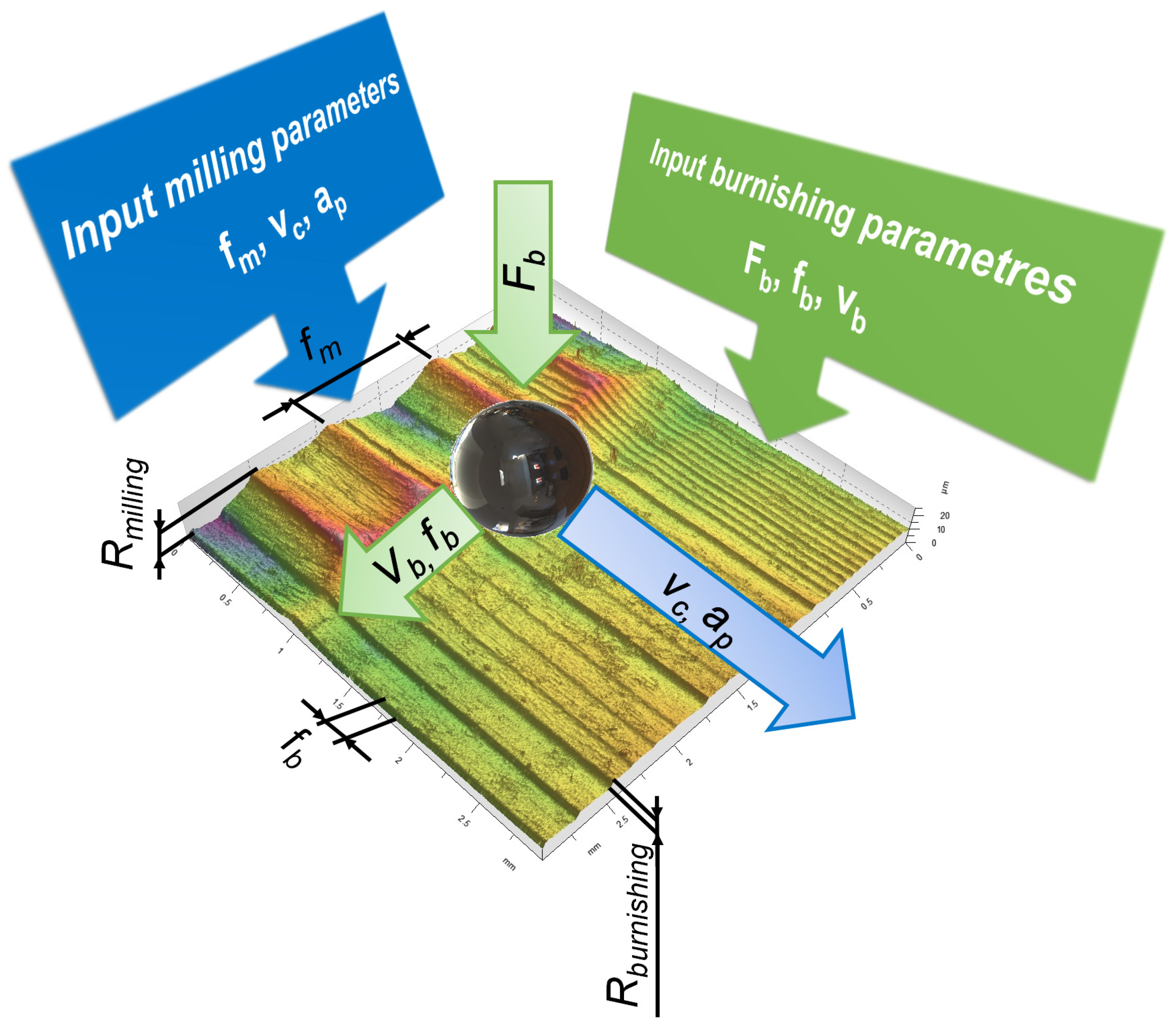
Figure 2. Input process parameters of hybrid machining process by milling and burnishing and output surface roughness.
Lubricants 12 00458 g002
Figure 3. Tests of tribological wear of specimen surfaces after burnishing: (a) View of the specimen on the tribological bench; (b) Measurement of the surface geometrical texture of the specimens after completion of all series of tribological tests.
Lubricants 12 00458 g003
Figure 4. Surfaces of specimens for (a) D8, after milling at fm = 0.4 mm and burnishing with force Fb = 600 N; (b) G8, after milling at fm = 0.7 mm and burnishing with force Fb = 600 N.
Lubricants 12 00458 g004
Figure 5. Surfaces of specimens for (a) D6, after milling at fm = 0.4 mm and burnishing with force Fb = 200 N; (b) G6, after milling at fm = 0.7 mm and burnishing with force Fb = 200 N.
Lubricants 12 00458 g005
Figure 6. Values of reference surface roughness after hybrid milling and burnishing: (a) Values of selected surface roughness height indices; (b) Values of functional indices.
Lubricants 12 00458 g006
Figure 7. Heights of surface irregularities (wear tracks) resulting from tribological tests.
Lubricants 12 00458 g007
Figure 8. Changes in the values of surface functional indices (wear tracks) resulting from tribological tests.
Lubricants 12 00458 g008
Figure 9. Example set of surface wear test results for specimen G6: (a) View of the surface of the specimen with traces after all tribological tests; (b) Surface profile after wear track extraction.
Lubricants 12 00458 g009
Figure 10. Changes in the degree of wear determined during experimental tests.
Lubricants 12 00458 g010
Figure 11. Image from metallographic examination of the surface after milling and burnishing for (a) Specimen G6 with high wear resistance; (b) Specimen D8 with low wear resistance.
Lubricants 12 00458 g011
Table 1. Technological parameters of milling and burnishing operations with the results of profile measurements, where the expanded uncertainty of parameter measurement was URa = 0.35 μm, URz = 0.94 μm and URmax = 0.59 μm.
Specimenfm (mm)Fb (N)Ra 1 (μm)Rz 1 (μm)Rmax 1 (μm)
D10Reference milling5.5621.622.2
D80.46000.944.444.87
D60.42000.884.004.46
G10Reference milling6.2925.327.2
G80.76002.9410.611.1
G60.72002.649.8010.6
1 Average value of the parameter.
Table 2. Mean values of the surface geometrical texture measurements obtained during the experimental tests, where the expanded uncertainty of the parameter measurement was USa = 0.18 μm, USz = 3.49 μm, USp = 3.01 μm, USv = 2.52 μm, UVmp = 0.04 μm, UVmc = 0.84 μm, UVvc = 0.73 μm and UVvv = 0.09 μm.
Friction Path (m)Specimen S a ¯ (μm) S z ¯ (μm) S p ¯ (μm) S v ¯ (μm) V m p ¯ (mL/mm2) V m c ¯ (mL/mm2) V v c ¯ (mL/mm2) V v v ¯ (mL/mm2)
0D81.1417.309.867.430.0881.7362.2120.239
D61.2216.968.388.580.0851.9472.3980.297
G81.2916.738.098.630.0872.0472.5710.304
G61.2416.399.087.320.0842.0422.5440.315
200D81.3019.6010.29.370.0892.0082.5100.297
D61.3416.697.938.760.0852.0452.4900.297
G81.3716.798.778.020.0922.0242.6010.279
G61.3218.698.879.820.0922.0692.5730.315
400D81.3520.6110.79.930.0852.2562.7050.350
D61.3718.069.478.600.0892.4052.8850.352
G81.4517.659.598.060.0962.2042.8380.308
G61.3618.988.7910.20.0942.1162.6690.305
600D81.5027.3414.912.40.0943.2883.4810.459
D61.4221.6110.910.70.0903.0303.3550.389
G81.4719.9711.48.600.0992.5043.1400.330
G61.3716.538.308.230.0952.5643.1580.345
800D81.5431.1115.915.20.0923.7423.8270.433
D61.5523.6313.510.20.1263.8914.4460.398
G81.5022.3911.311.10.1103.4594.0370.365
G61.5022.5212.89.740.1094.1764.4170.450
Table 3. Results of Vickers surface hardness measurements (HV1).
SpecimenHV1S
D10 Reference milling1896
D829515
D631414
G10 Reference milling1896
G833211
G634612
Table 4. The average values of the wear track dimensions obtained during the test and the values of the determined degree of wear.
Friction Path (m)SpecimenW (mm)D (μm)A (μm2)Norm(W)Norm(D)Norm(A)Sum(WDA)DOW
200D80.2952.8435320.2340.2350.0930.5620.161
D60.3261.4844390.3280.0550.0630.4460.123
G80.3051.0702430.2650.0000.0010.2660.063
G60.2171.6602410.0000.0780.0000.0780.000
400D80.3572.9988500.4210.2560.1950.8720.264
D60.3882.4009360.5150.1760.2220.9130.278
G80.3222.5707040.3170.1990.1480.6640.195
G60.2331.4802870.0480.0540.0150.1170.013
600D80.5493.79317261.0000.3610.4751.8360.586
D60.4402.99213280.6730.2550.3471.2750.399
G80.3973.62011850.5430.3380.3021.1830.368
G60.3003.85011090.2500.3690.2770.8960.273
800D80.5335.16423840.9530.5430.6852.1810.701
D60.5025.43526140.8600.5790.7582.1970.706
G80.4315.85022180.6450.6340.6321.9110.611
G60.3168.61033700.2991.0001.0002.2990.740
Disclaimer/Publisher’s Note: The statements, opinions and data contained in all publications are solely those of the individual author(s) and contributor(s) and not of MDPI and/or the editor(s). MDPI and/or the editor(s) disclaim responsibility for any injury to people or property resulting from any ideas, methods, instructions or products referred to in the content.