Article

Influence of Molybdenum Addition on the Structure, Mechanical Properties, and Cutting Performance of AlTiN Coatings

1
International Joint Institute of Advanced Coating Technology, Taizhou University, Taizhou 318000, China
2
Wenling Research Institute of Taizhou University, Taizhou 318000, China
3
Zhejiang Provincial Key Laboratory for Cutting Tools, Taizhou University, Taizhou 318000, China
4
College of Biological and Chemical Engineering, Zhejiang University of Science and Technology, Hangzhou 310000, China
5
Civil Aviation Department, Zhejiang Institute of Communication, Hangzhou 311112, China
6
Metal-Polymer Research Institute, National Academy of Sciences of Belarus, 246050 Gomel, Belarus
*
Authors to whom correspondence should be addressed.
Lubricants 2024, 12(12), 429; https://doi.org/10.3390/lubricants12120429
Submission received: 25 October 2024 / Revised: 29 November 2024 / Accepted: 2 December 2024 / Published: 3 December 2024
(This article belongs to the Special Issue Wear-Resistant Coatings and Film Materials)

Abstract

:
Though AlTiN coating has been intensively studied, there is still a need to develop AlTiN coating to meet the growing demand of industrial machining. One effective way to improve the performance of AlTiN coating is by adding alloying elements. In this study, AlTiN and AlTiMo coatings were deposited using multi-arc ion plating to investigate the influence of molybdenum addition on the structure, mechanical properties, and cutting performance of AlTiN coatings. Spherical droplets formed on the surfaces of both coatings, with the AlTiMoN coating exhibiting more surface defects than the AlTiN coating. The grazing incidence X-ray diffraction results revealed the formation of an (Al,Ti)N phase formed in the AlTiN and AlTiMoN coatings. Molybdenum doping in the AlTiMoN coating slightly reduced the grain size. Both coatings exhibited excellent adhesion to the substrate. The hardness (H), elastic moduli (E), H/E, and H3/E2 ratios of the AlTiMoN coating were higher than those of the AlTiN coating. The improvement in the mechanical properties was attributed to grain refinement and solution strengthening. Molybdenum doping improved the tribological properties and cutting performance of the AlTiN coatings, which was ascribed to the formation of MoO3 as a solid lubricant. These results show a path to increase the performance of AlTiN coating through molybdenum addition and provide ideas for the application of AlTiMoN coatings for cutting tools.

1. Introduction

Metal nitride coatings have been widely used as hard protective coatings in various industries, especially in machining and forming processes. Among them, TiN coatings were developed as the first generation of metal nitride coatings for protecting various tool materials. However, TiN coatings have been gradually replaced because of their limited mechanical and tribological properties [1]. Furthermore, TiN coatings are unstable and rapidly oxidize above 500 °C [2].
Combining TiN coatings with Al significantly improves the hardness, wear resistance, thermal stability, and oxidation resistance of AlTiN coatings [3]. The improved hardness of AlTiN coatings is attributed to an increase in the internal strain of the lattice owing to the substitution of Ti atoms with Al atoms [1]. AlTiN coatings exhibit hardnesses of up to 30 GPa [4]. AlTiN coatings exhibit more effective wear and oxidation resistance than TiN coatings because an Al2O3 top layer is formed during friction, which prevents further oxidation and reduces the coefficient of friction (COF) [5]. AlTiN coatings remain stable in the single-phase cubic structure at 800 °C/1 h with only a 250-nanometer-thick surface layer oxidation [6], indicating that the coating has high thermal stability and is suitable for high-speed cutting operations.
AlTiN wear-resistant coatings exhibit serious disadvantages, namely a high COF exceeding 0.7 at room and high temperatures [7]. High COF increases the tool temperature and accelerates the wear process during cutting. The mechanical and tribological properties and cutting performance of AlTiN coatings must be further improved. The development of AlTiN coatings via the addition of alloying elements has gained extensive attention [8,9].
Molybdenum is a promising alloying element for AlTiN coatings because its introduction improves the mechanical performance, tribological properties, and oxidation resistance of AlTiN coatings [10,11,12,13,14]. In particular, the inclusion of Mo in AlTiN coatings results in the formation of a MoO3 phase during friction. MoO3, known as the Magnéli phase, is regarded as a solid–lubricant oxide [15]. MoO3 is composed of layers bonded by van der Waals forces that easily deform under shearing force, effectively reducing the COF [16,17,18]. These coatings have attracted extensive attention owing to their excellent comprehensive properties. Tavares investigated the influence of the N2 flow, Ar partial pressure, and bias voltage on the structure, mechanical properties, and thermal stability of multilayered AlTiMoN coatings [19,20,21,22,23,24]. Thereafter, several studies have been conducted on the effect of the deposition parameters (bias voltage [17,25], N2 pressure [17,25], and rotation speed [18,26,27,28]) on the structure and properties (smoothness, hardness, fracture toughness, wear behavior, and tribological properties) of AlTiMoN coatings. Several studies investigated the influence of the Mo content on the microstructure, wettability, mechanical performance, corrosion resistance, thermal stability, and tribological properties of the AlTiMoN coating system. However, few studies have focused on the cutting performance of AlTiMoN coatings [10,12,13,16,29,30,31,32,33,34]. AlTiN-based hard coatings are often used as protective coatings on cutting tools; therefore, it is necessary to study the cutting performance of AlTiMoN coatings.
AlTiN and AlTiMoN coatings were prepared in this study using multi-arc ion plating, and the effect of Mo addition on the structure, mechanical properties, and cutting performance of the AlTiN coatings was investigated. This study aimed to develop an AlTiMoN coating for cutting tools and provide ideas for the application of AlTiMoN coatings prepared using multi-arc ion plating in machining and forming applications.

2. Materials and Methods

AlTiN and AlTiMoN coatings were deposited on two different substrates, namely YG8 cemented carbide sheets (16 mm × 16 mm × 4.5 mm) and YT15 carbide blades. The coatings prepared on the carbide sheets were used for structural characterization and mechanical performance testing, while the coatings prepared on the carbide blades were employed for evaluating the cutting performance. The substrates were ultrasonically cleaned before use. Ultrasonic cleaning was first performed in an acetone solution at 45 °C for 20 min, followed by ultrasonic cleaning in anhydrous ethanol at 45 °C for 20 min.
The coatings were deposited using a multi-arc ion plating apparatus (SP-0806ASI, Beijing Powertech Technology Co., Ltd., Beijing, China). Three Φ100 mm × 30 mm cylindrical targets, namely Ti, Al67Ti33, and Al60Ti30Mo10 targets, with 99% purity were employed.
Before deposition, the temperature and pressure of the vacuum chamber were set to 400 °C and 9 × 10⁻³ Pa, respectively. The substrate and sample holder rotations were initiated, and the rotation speeds were set to 2 and 6 rpm, respectively. Argon (50 sccm) was injected into the cavity, and the substrate was etched using Ti plasma for 5 min to eliminate pollutants. The bias voltage, arc current, frequency, and pulse width of the etching process were −800 V, 60 A, 20 KHz, and 10 μs, respectively. After etching, a Ti interlayer was deposited at a bias voltage, arc current, frequency, and pulse width of −400 V, 60 A, 10 KHz, and 40 μs, respectively. The Ti layer deposition time was set to 30 min. Finally, AlTiN and AlTiMoN coatings were deposited at a bias voltage, arc current, frequency, and pulse width of −150 V, 60 A, 75 KHz, and 10 μs, respectively. The N2/Ar gas flow rates for the AlTiN and AlTiMoN coatings were 320/20 and 200/20 sccm, respectively. Both coatings were deposited for 180 min.
The hardness (H) and elastic moduli (E) of the AlTiN and AlTiMoN coatings were evaluated using a nano-indenter (Nano Test Vantage, Micro Materials, Wrexham, UK). The international standard ISO 14577 was adopted [35]. The hardness evaluations were performed using a Berkovich diamond indenter with a maximum indentation load of 30 mN. The loading, peak load holding, and unloading times were 30 s, 60 s, and 30 s, respectively. The Oliver–Phar method was adopted to calculate the hardness and elastic moduli of the coatings [36]. Poisson’s ratios of the indenter and coatings were 0.07 and 0.18, respectively. Ten indentations were performed on each sample to reduce measurement errors.
The friction and wear behaviors were tested using a reciprocating friction and wear testing machine (MFT-5000, Rtec Instruments, San Jose, CA, USA). The standard ASTM G137 was adopted [37]. Friction testing was conducted at 25 °C for 60 min at a relative humidity of approximately 60%. The tribotest was performed using a 6-milimeter-diameter Si3N4 ball. The applied load, sliding distance of a single stroke, and test frequency were 10 N, 5 mm, and 2 Hz, respectively. Two samples were used in the tribological test in order to reduce experimental error. After the tribotests, white-light interferometry (Lambda, Rtec Instruments, San Jose, CA, USA) was used to observe the wear. The wear rate (W) was calculated according to Ref. [38]:
W = V / (F · L)
where V (mm3) is the wear volume of the coating, F (N) is the applied load, and L (m) is the sliding distance. V was obtained by analyzing the wear tracks using MountainsMap Imaging Topography 9 software. Two wear tracks were selected to calculate the respective wear rates, and the average value was taken as the wear rate.
The coating adhesion was qualitatively investigated using Rockwell-C indentation according to the JB/T 11442-2013 [39]. The Rockwell-C indentation tests employed a load of 588 N (60 kgf) and a diamond cone indenter with an angle of 120°. Optical microscopy (ZEISS AXIO Scope.A1, Oberkochen, Germany) was used to obtain indentation images after the Rockwell-C indentation tests.
A Computer Numerical Control machine tool (CK6140S, Zhejiang Kaida Machine Tool Co., Ltd., Zhuji, China) was used for the cutting experiment according to the GB/T 16461-2016 [40]. The workpiece material was a No. 45 steel round rod with a diameter of 50 mm. The cutting parameters have a remarkable influence on cutting quality and surface finish, and the assignment of cutting parameters should be considered comprehensively. According to the recommendations of cutting tool manufacturer, existing industry practice, and research references, the common ranges of the cutting speed, cutting depth, and feed rate for steel are 40–250 m/min, 0.2–0.5 mm, and 0.1–0.3 mm/r. Therefore, within the range of the above process parameters, the cutting speed, cutting depth, and feed rate in this study were set at 80 m/min, 0.5 mm, and 0.25 mm/r, respectively. A dynamometer (9257 B) and thermal imager (A655SC) were employed to analyze the cutting force and cutting temperature, respectively.
Scanning electron microscopy (SEM; S4800, Hitachi, Tokyo, Japan) was used to examine the surface and cross-sectional morphologies of the coatings. The coating composition was analyzed using energy-dispersive X-ray spectroscopy (EDS). Three different regions were selected for EDS analysis, and the average value of the result was taken as the element component. The phase structures of the AlTiN and AlTiMoN coatings were characterized using grazing incidence X-ray diffraction (GIXRD, D8 Advance, Bruker, Saarbruecken, Germany) with Cu-Ka radiation (40 kV, 100 mA) in a grazing mode (0.1°). The scanning range, step size, and scanning speed of the GIXRD analyses were 20°~80°, 0.02°, and 0.03°/s, respectively. The crystallite sizes of the AlTiN and AlTiMoN coatings were calculated using the Scherrer formula (Equation (2)) [10]:
D = kλ / (β · θ)
where k is the shape factor (k = 0.94), λ is the X-ray wavelength (λCu = 0.154 nm), β is the full width–half maximum, and θ is the Bragg angle.

3. Result and Discussion

3.1. Structural Characterization of the AlTiN and AlTiMoN Coatings

Figure 1 shows the surface and cross-sectional morphologies of the AlTiN and AlTiMoN coatings. As shown in Figure 1, spherical droplets [41] formed on the surfaces of both coatings. Figure 1a,b show that the number of droplets on the surface of the AlTiMoN coating was significantly higher than that on the surface of the AlTiN coating. Additionally, the droplets on the AlTiMoN-coated surface were coarse. These results indicate that the AlTiMoN coating had more surface defects than the AlTiN coating. This can be attributed to two factors. First, the thermal conductivity of Mo is higher than that of Ti (a higher thermal conductivity coefficient implies that the cooling of microdroplets is faster, which indicates that the probability of solidification of Mo droplets before contacting the surface is higher than that of Ti droplets [41]). Additionally, Mo has a higher melting point than Al and Ti; therefore, Mo is more difficult to ionize during deposition. Research suggests that, owing to fast evaporation during cathode ion plating, the un-ionized atoms of the target material reach the substrate surface and form droplet particles [26].
Table 1 lists the elemental compositions of the AlTiN and AlTiMoN coatings determined using EDS; the Al, Ti, and N contents in the AlTiMoN coating, as compared with those in the AlTiN coating, were slightly reduced, and the Mo was 5.1%.
Figure 1c,d show that both coatings consisted of two layers, namely, an outer AlTiN or AlTiMoN layer and an inner Ti layer. The thicknesses of the AlTiN and AlTiMoN coatings were 3.41 and 2.75 μm, respectively. The thickness of the thicker AlTiN coating was expected owing to the higher total pressure in the chamber during the AlTiN coating deposition process. The probability of ions colliding with gas atoms increases with an increasing total pressure in the chamber; thus, the ion mobility, impinging energy, and resputtering efficiency decrease, increasing the deposition rate [42]. Both the AlTiN and AlTiMoN coatings exhibited typical columnar structures arranged perpendicular to the substrate. Belgroune reported that Mo addition of up to 16% in AlTiN coatings densified the coatings without the formation of a columnar structure and that the coating structure changed from zone II to zone T based on the Anders’s structural zone model [30]. In this study, approximately 5.1% Mo was added to the coating, indicating that the low Mo addition used in this study cannot change the coating structure.
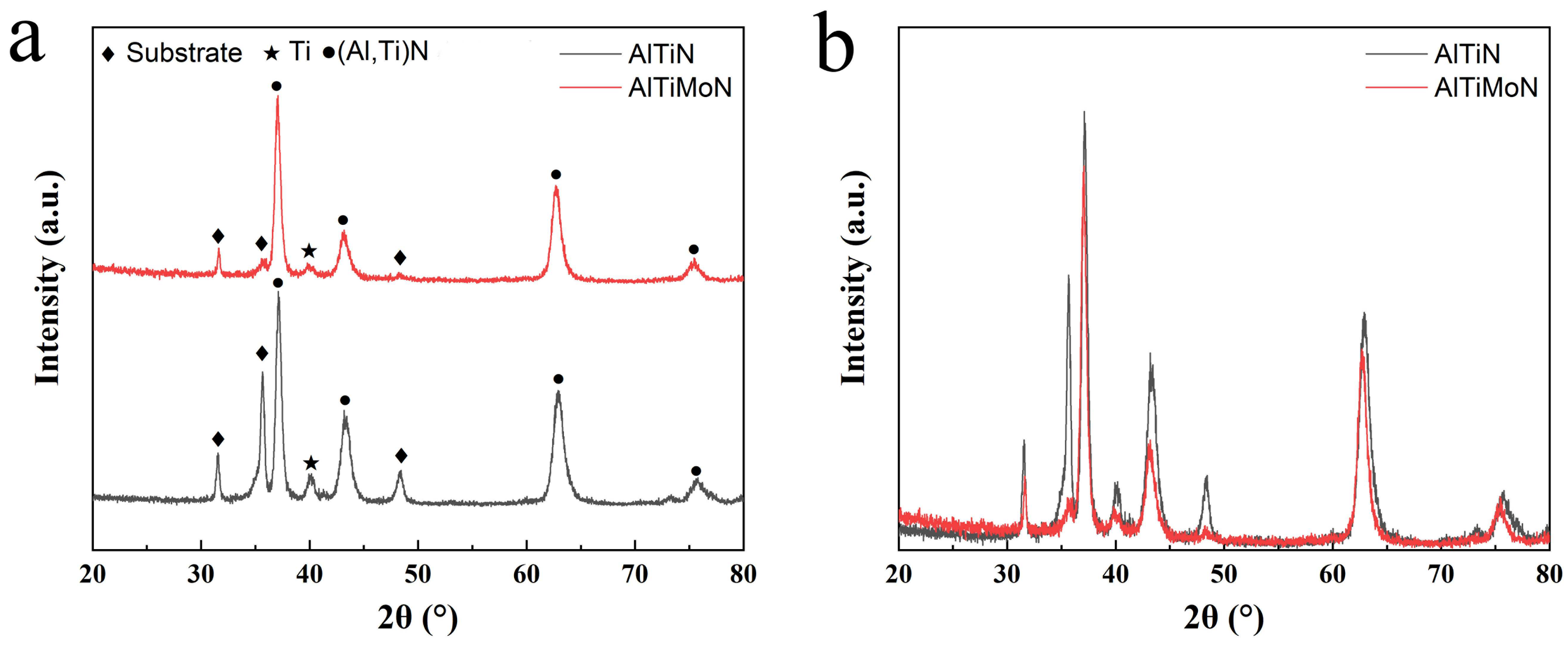
Figure 2 shows the GIXRD patterns of the AlTiN and AlTiMoN coatings. A diffraction peak was detected in both coatings at a 2θ of approximately 40°, which corresponds to the Ti layer in both coatings. Figure 2 also shows diffraction peaks of the substrate (mainly tungsten carbide). The remaining peaks were attributed to metallic nitrides, which were the main phase components. The peak positions of the (Al,Ti)N phase in the AlTiN coating were located at 37.1°, 43.3°, 63.0°, and 75.8°, which correspond to the (111), (200), (220), and (311) planes, respectively. The GIXRD pattern of the AlTiN coating shows that the (Al,Ti)N phase has a face-centered cubic (fcc) B1-NaCl structure. Compared to the standard TiN diffraction peaks, the peak positions of the (Al,Ti)N phase shifted by a small angle, which indicates that part of the Ti in the cubic TiN lattice was replaced by Al with a smaller atomic radius. This result was similar to the XRD results reported in Ref. [28]. The formation of the (Al,Ti)N phase was also observed in the AlTiMoN coating. The peaks of the (Al,Ti)N phase were located at 37.1°, 43.2°, 62.7°, and 75.4°, corresponding to the (111), (200), (220), and (311) planes, respectively. The addition of Mo to the AlTiMoN coating shifted the peak positions of the (Al,Ti)N phase to lower angles (Figure 2b), owing to the substitution of Mo atoms [12,30]. No peaks corresponding to pure metallic Mo were observed, which may be related to the low content of pure metallic Mo in the AlTiMoN coating. The diffraction angles of the corresponding peaks of the (Al,Ti)N and Mo2N phases were close to each other, and it is difficult to distinguish from the GIXRD results whether the Mo2N phase exists. The Mo2N phase was found in the AlTiMoN coating with 8% Mo addition in some studies [17,25,34]. XPS may be needed to further determine whether the MoN2 phase exists in the AlTiMoN coating with a 5% Mo addition in this study.
Based on the Debye–Scherrer equation, the peaks of (Al,Ti)N (111), (200), (222), and (311) were selected, and the average grain sizes of the AlTiN and AlTiMoN coatings were calculated using GIXRD data analysis. The grain sizes of the AlTiN and AlTiMoN coatings were approximately 14 and 11 nm, respectively. Thus, the addition of Mo slightly reduced grain size, which is consistent with previously reported results [10,30]. Gao reported that the addition of 8% Mo reduced the grain size of AlTiN coatings from 30 to 28 nm [10]. Belgroune reported that the addition of 4% Mo to an AlTiN coating reduced the grain size of the coating from 58 to 55 nm [30].

3.2. Mechanical Properties of the AlTiN and AlTiMoN Coatings

The adhesion properties of the AlTiN and AlTiMoN coatings on the cemented carbide substrate were evaluated using Rockwell-C indentation. Figure 3 shows images of the indentations after the indentation tests. Only a few tiny cracks are visible around the indentation, as shown by the red arrow in Figure 3. No indication of spallation was observed. Radial cracking without chipping indicates that both coatings exhibited excellent adhesion (HF1 level) and that Mo did not significantly influence the adhesion properties of the AlTiN coatings. This may be because of the favorable effect of the deposited Ti interlayer on improving the adhesion properties between the coating and the substrate. The Ti interlayer can reduce the difference in the physical and mechanical properties between the nitride coating and substrate; therefore, the stress gradient at the interface is lowered [12]. Both coatings exhibited excellent adhesion to the substrate.
Table 2 lists the H and E of the AlTiN and AlTiMoN coatings. The H and E of the AlTiN coating were 26 and 318 GPa, respectively. The H and E of the AlTiMoN coating increased to 30 and 341 GPa, respectively. The addition of Mo clearly increased the H and E values of the AlTiN coating. Furthermore, the AlTiMoN coating exhibited higher H/E and H3/E2 ratios.
The AlTiMoN coating exhibited a higher hardness than the AlTiN coating because (1) the grain size of the AlTiMoN coating is finer than that of the AlTiN coating; thus, the increase in hardness is related to grain refinement strengthening [30]; (2) the increased hardness is related to the increased solution-strengthening effect from the substitution of Ti atoms with Mo atoms [10,12].
The increase in the elastic modulus of the coating owing to the Mo addition can be attributed to the substitution of Mo atoms. The Ti atoms are replaced by Mo atoms, resulting in a smaller lattice. Smaller interatomic spaces result in greater binding forces, which facilitates improvements in the elastic modulus [43].
The values of H/E and H3/E2 indicate the wear resistance of coatings and can be used to predict their tribological behavior [44,45]. The H/E and H3/E2 ratios of the AlTiMoN coating with added Mo were higher than those of the AlTiN coating, which should result in better wear resistance and tribological behavior.

3.3. Tribological Properties of the AlTiN and AlTiMoN Coatings

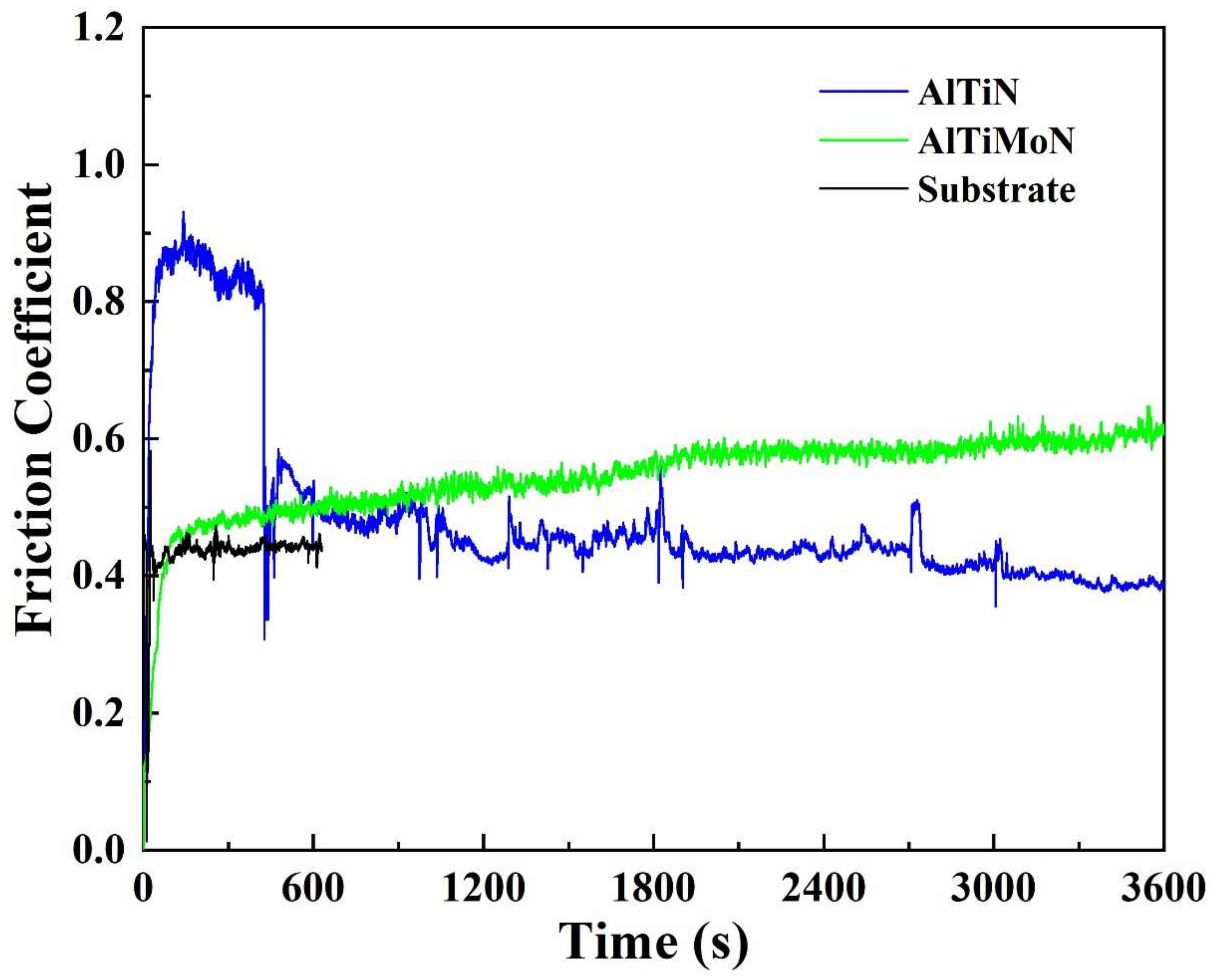
Figure 4 shows the COFs of the AlTiN and AlTiMoN coatings under 10 N with a sliding duration of 3600 s, as well as the COF of the substrate. As shown in Figure 4, the COF of the substrate is stable and low at approximately 0.45. The COF of the AlTiMoN coating is stable and exhibits a progressively increasing trend. The COF of the AlTiMoN coating is approximately 0.60. The COF of the AlTiN coating exhibits two distinct stages, that is, it first increased and then decreased, and then finally stabilized. The first stage of the curve lasts for approximately 430 s, during which the COF is approximately 0.85. Subsequently, the COF decreases rapidly and then fluctuates at approximately 0.45. Notably, the second stage of the COF curve is similar to that of the substrate, which suggests the COF reduced from 0.85 to 0.45 because the AlTiN coating was abraded. Therefore, the COF of 0.85 is the COF of the AlTiN coating during the first stage, and the COF of 0.45 is the COF of the substrate during the second stage. The COF of the AlTiMoN coating is lower than that of the AlTiN coating.
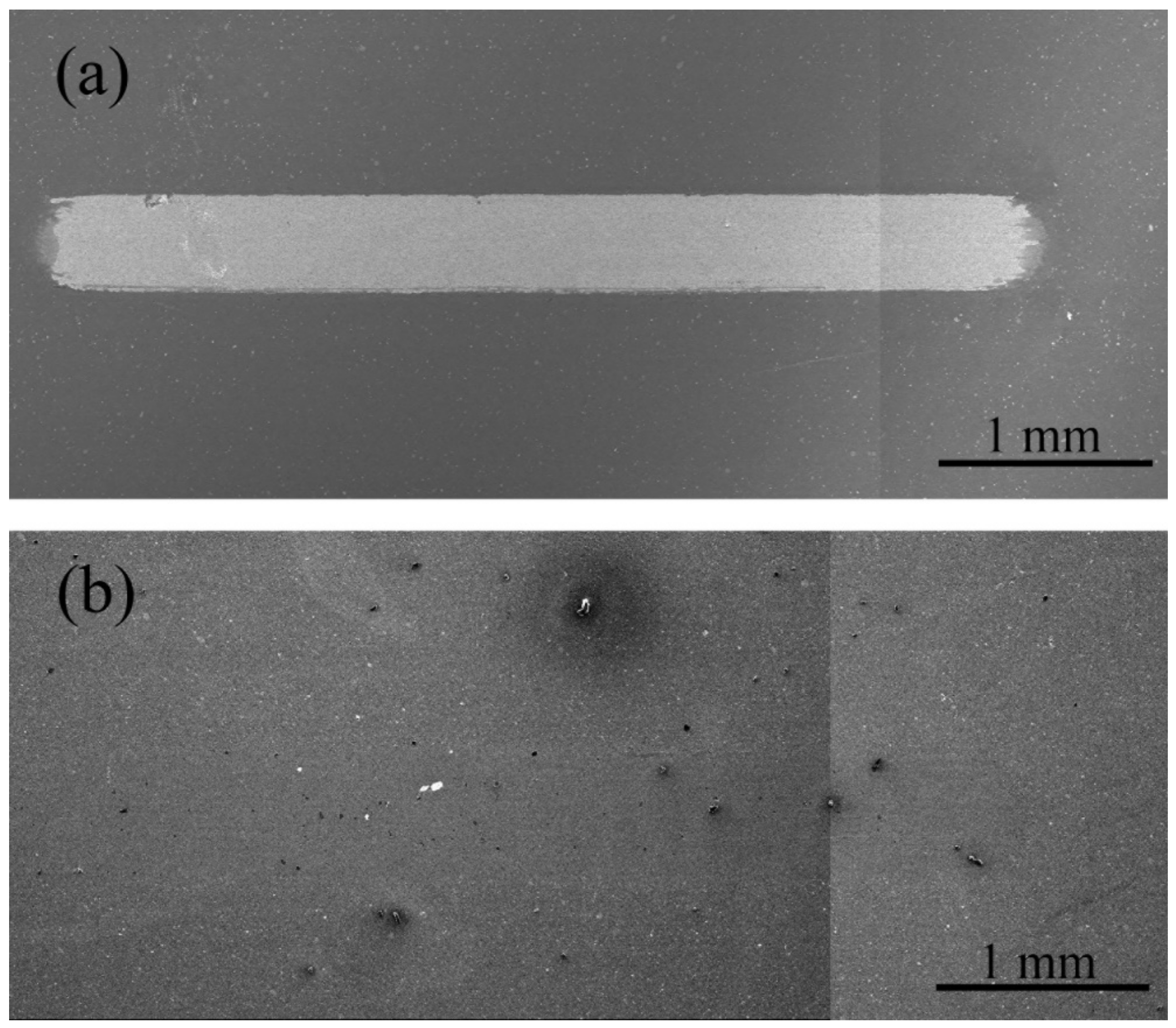
Figure 5 shows the SEM topographies of the wear tracks on the AlTiN and AlTiMoN coatings. The metal substrate is exposed in Figure 5a, indicating that the AlTiN coating was completely abraded. In contrast, the AlTiMoN coating in Figure 5b does not exhibit peeling. The worn surface of the AlTiMoN coating is smooth and clean, except for small holes observed on the wear track. Table 3 lists the elemental compositions of the wear tracks on the AlTiN and AlTiMoN coatings. Tungsten and Co, originating from the cemented carbide substrate, appeared in the wear track of the AlTiN coating, indicating that the AlTiN coating was completely abraded. However, no W or Co was found in the wear track of the AlTiMoN coating, indicating that the AlTiMoN coating was not completely abraded, which is consistent with the SEM observations shown in Figure 5.
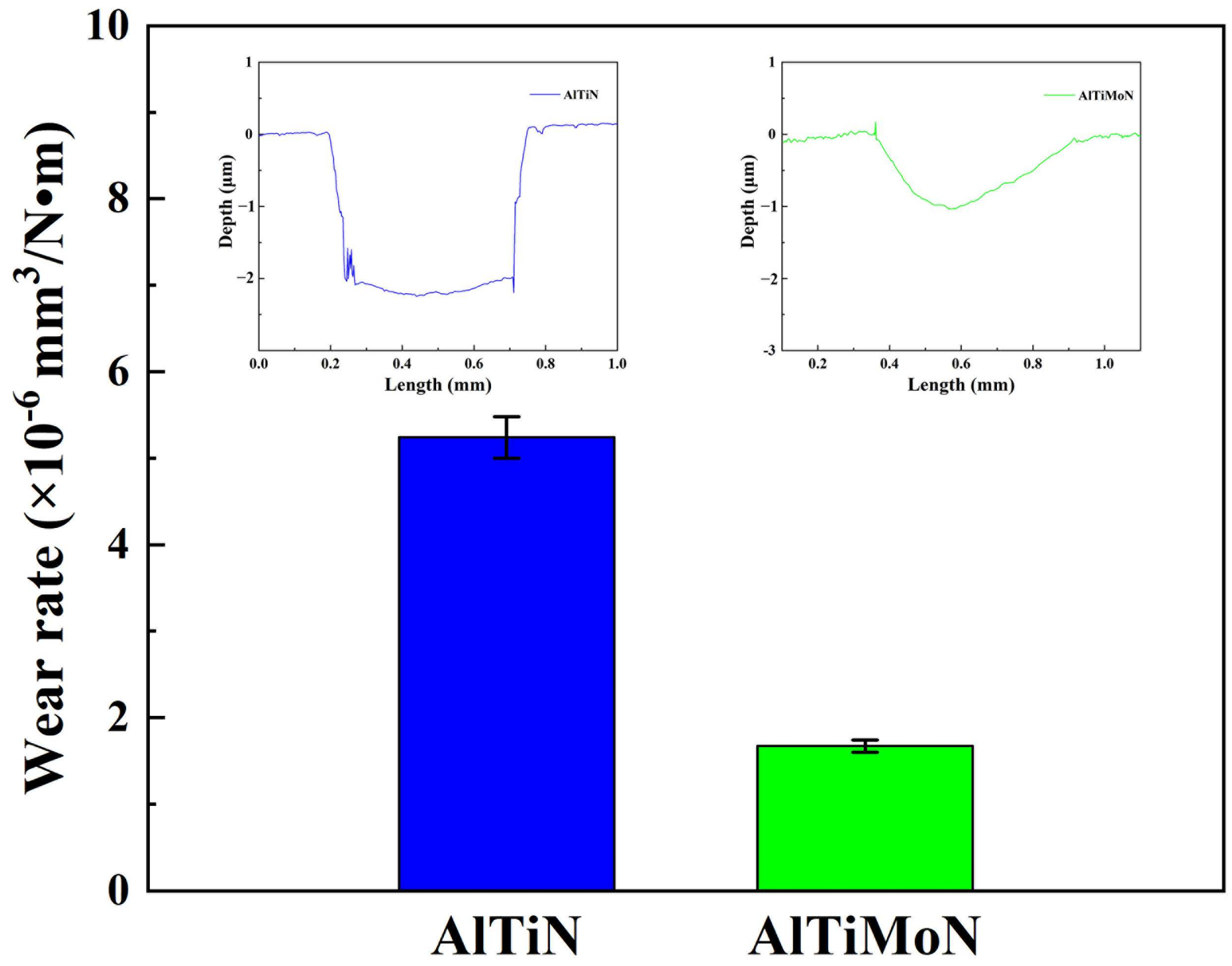
Figure 6 shows the wear rates of the AlTiN (5.24 × 10⁻⁶ mm3/(N·m)) and AlTiMoN coatings (1.67 × 10⁻⁶ mm3/(N·m)). The wear rate of the AlTiMoN coating is lower than that of the AlTiN coating. The results indicate that the addition of Mo increased the wear resistance of the AlTiN coating.
The heat generated by sliding friction can sufficiently increase the temperature of the contact surface for oxidation to occur. TiO2 and Al2O3 phases were formed in the wear track during dry friction of the AlTiN coating. These phases have low ionic potentials, and the cations between them can strongly interact to form strong ionic or covalent bonds, making them difficult to shear [46]. Accordingly, the formation of an oxide layer or wear debris patches of such oxides does not provide any lubricious effect, resulting in a high COF [44]. Additionally, the TiO2 and Al2O3 oxidation phases are hard and act as abrasive particles during the wear tests, causing abrasive wear [10]. Leyland and Tsui reported that lower H/E and H3/E2 values indicate diminished wear resistance [44,45]. Thus, the AlTiN coating failed due to abrasion during sliding, which caused the coating to delaminate, thereby exposing the substrate. The coating failed owing to the low H/E and H3/E2 values and high COF.
Molybdenum doping enhanced the tribological properties and wear resistance of the AlTiN coatings. The COF decreased from 0.85 (AlTiN coating) to 0.60 (AlTiMoN coating), and the wear rate of the AlTiMoN coating was reduced to one-third of that of the AlTiN coating. In addition to the TiO2 and Al2O3 phases, the MoO3 phases were also formed on the wear track of the AlTiMoN coating during dry friction. The layered structure of MoO3 is bonded by weak van der Waals forces; therefore, MoO3 is easily sheared layer by layer. Soft and non-abrasive MoO3 can be used as a solid lubricant to reduce the friction between friction pairs. The wear resistance improvement of the AlTiMoN coating is also attributed to the beneficial contribution of the MoO3 phases, which exhibit self-lubricating properties and facilitate the sliding processes. Moreover, the improved wear resistance of the AlTiMoN coating is related to its higher H/E and H3/E2 ratios [10,11,12,13,16,17,18,26,28,29,30,31,32,47].

3.4. Cutting Performance of the AlTiN and AlTiMoN Coatings

Figure 7 shows a schematic diagram illustrating the cutting force direction of the cutting tool. The cutting forces can be divided into three directions, namely, the Fx (feed force) direction is opposite to the direction of feed movement, the Fy (tangential force) direction is horizontally outward, and the Fz (radial thrust force) direction is vertically downward. Figure 8 shows the cutting forces on the AlTiN- and AlTiMoN-coated tools measured using a force meter during cutting. Figure 8 clearly shows that the cutting force in the Fz direction is more stable than that in the other two directions for both coatings. Specifically, the average cutting forces on the AlTiMoN-coated tool were Fx = 197.4 N, Fy = 302.4 N, and Fz = 195.4 N. The average cutting forces on the AlTiN-coated tool were Fx = 239.2 N, Fy = 345.7 N, and Fz = 233.8 N. The experimental results showed that the forces on the AlTiMoN-coated tool in all three directions were smaller than those on the AlTiN-coated tool, indicating that the addition of Mo resulted in the AlTiN-coated tool exhibiting lower cutting forces.
The cutting temperatures of the AlTiMoN- and AlTiN-coated tools during the cutting process were measured using an A655sc thermal imager. Table 4 shows that the highest cutting temperatures of the AlTiMoN- and AlTiN-coated tools were 577 and 611 °C, respectively. Additionally, the average temperatures of the AlTiMoN- and AlTiN-coated tools at which cutting was stable were approximately 560 and 596 °C, respectively. Therefore, the highest cutting temperature of the AlTiMoN-coated tool was 34 °C lower than that of the AlTiN-coated tool, and the average cutting temperature at which cutting was stable was 36 °C lower than that of the AlTiN-coated tool. Therefore, it can be concluded that the AlTiMoN coating was more effective than the AlTiN coating in reducing the cutting temperature of cutting tools during the cutting process.
Cutting tools produce unavoidable heat during the cutting process. Therefore, cutting heat is the primary reason for the increase in the cutting temperature. A high cutting temperature oxidizes or even causes the coating on the tool surface to fail, which directly impacts the machining accuracy and surface quality of the workpiece.
TiO2 and Al2O3 phases formed during the cutting process of the AlTiN coating. The formation of the TiO2 and Al2O3 phases by a possible reaction during the cutting process may be as follows:
2TiN + 2O2 = 2TiO2 + N2
2AlN + 3/2O2 = Al2O3 + N2
These oxides have low ionic potentials, and the cations between them can strongly interact to form strong ionic or covalent bonds. As a result, these oxides are not easily deformed under shearing force and do not have any lubricating effect [46]. What is worse, the TiO2 and Al2O3 oxides are hard and act as abrasive particles, which are detrimental to the cutting process. Owing to the above reasons, the cutting force and temperature of the AlTiN-coated tools were high during the cutting process.
The oxidation temperature of Mo nitride films is approximately 350–400 °C [12], and the melting point for the lubricious oxide MoO3 is 795 °C [48]. Consequently, the solid–lubricant MoO3 phase formed during the cutting process of the AlTiMoN coating, though the TiO2 and Al2O3 phases were also formed. The formation of the MoO3 phase by tribo-chemical reaction during the cutting process may be as follows [30]:
Mo2N + 2O2 = 2MoO2 + 1/2N2
MoO2 + 1/2O2 = MoO3
or
Mo + 3/2O2 = MoO3
MoO3 phase is a solid-lubricant oxide, which is composed of layers bonded by van der Waals forces that easily deform under shearing force. The existence of the soft and non-abrasive MoO3 phase minimized friction between the tool and chip interfaces, thereby reducing the cutting force and heat generated during machining. Xing [49] and Li [50] found that the formation of a lubricating phase with a low shear strength between the tool and chip interfaces contributes to the improvement of the cutting performance. Low cutting forces and temperatures result in low wear and a long tool life.
In summary, Mo addition improves the mechanical performance, tribological properties, wear resistance, and cutting performance of AlTiN coatings. This study shows a path to increase the performance of AlTiN coating through molybdenum addition and provides ideas for the application of AlTiMoN coatings for cutting tools.

4. Conclusions

AlTiN and AlTiMo coatings were deposited in this study using multi-arc ion plating. The influence of Mo addition on the structure, mechanical properties, and cutting performance of the AlTiN coating was investigated. The main conclusions drawn from this study are as follows:
  • Spherical droplets formed on the surfaces of both coatings, with the AlTiMoN coating exhibiting more surface defects than the AlTiN coating. The GIXRD results for the AlTiN and AlTiMoN coatings showed that an (Al,Ti)N phase was formed. Doping of the AlTiMoN coating with Mo slightly reduced the grain size.
  • Both coatings exhibited excellent adhesion to the substrate. The hardness, elastic modulus, and H/E and H3/E2 ratios of the AlTiMoN coating were higher than those of the AlTiN coating. The improvement in the mechanical properties can be attributed to grain refinement and solution strengthening.
  • The tribological properties and cutting performance of the AlTiN coating improved with the Mo doping, which can be attributed to the formation of MoO3 as a solid lubricant.
The presented research focuses the Mo addition on the structure, mechanical properties, and cutting performance of the AlTiN coating. However, the effect of Mo composition on the structure and properties of the AlTiMoN coating is not involved, especially on the cutting performance. This is what our next research will focus on. In the field of advanced coating technologies for cutting tools, the cutting performance and tool life of coated tools can be further improved by using nano-layer and nano-composite coating. Future research can be focused on depositing nanolayered and nanocomposite AlTiMoN coatings to further improve the performance of AlTiMoN coatings for machining applications.

Author Contributions

Methodology, T.Y. and V.L.; investigation, J.Y. and T.Y.; resources, V.L.; data curation, J.Y. and P.Y.; writing—original draft preparation, P.Y.; writing—review and editing, T.Y., C.L., P.Z., J.W., A.K., M.H., A.Y.G. and D.M.G.; supervision, V.L.; project administration, T.W. All authors have read and agreed to the published version of the manuscript.

Funding

This research was funded by the Zhejiang Provincial Natural Science Foundation of China, grant numbers LQ22E010007 and LTZ20E020001; Wenling Key Research and Development Project, grant number 2023G00007; and Taizhou Science and Technology Plan Project, grant number 22gya09.

Data Availability Statement

The data presented in this study are available on request from the corresponding author. The data are not publicly available due to privacy.

Conflicts of Interest

The authors declare no conflicts of interest.

References

  1. Avila, R.F.; Mancosu, R.D.; Machado, A.R.; Vecchio, S.D.; Silva, R.B.d.; Vieira, J.M. Comparative analysis of wear on PVD TiN and (Ti1−xAlx)N coatings in machining process. Wear 2013, 302, 1192–1200. [Google Scholar] [CrossRef]
  2. Chauhan, K.V.; Rawal, S.K. A review paper on tribological and mechanical properties of ternary nitride based coatings. Procedia Technol. 2014, 14, 430–437. [Google Scholar] [CrossRef]
  3. PalDey, S.; Deevi, S.C. Single layer and multilayer wear resistant coatings of (Ti,Al)N: A review. Mater. Sci. Eng. A 2003, 342, 58–79. [Google Scholar] [CrossRef]
  4. Musil, J.; Hrubý, H. Superhard nanocomposite Ti1−xAlxN films prepared by magnetron sputtering. Thin Solid Films 2000, 365, 104–109. [Google Scholar] [CrossRef]
  5. Kale, A.N.; Ravindranath, K.; Kothari, D.C.; Raole, P.M. Tribological properties of (Ti,Al) N coatings deposited at different bias voltages using the cathodic arc technique. Surf. Coat. Technol. 2001, 145, 60–70. [Google Scholar] [CrossRef]
  6. Richthofen, A.; Cremer, R.; Witthaut, M.; Domnick, R.; Neuschütz, D. Composition, binding states, structure, and morphology of the corrosion layer of an oxidized Ti0.46Al0.54N film. Thin Solid Films 1998, 312, 190–194. [Google Scholar] [CrossRef]
  7. Hardell, J.; Prakash, B. Tribological performance of surface engineered tool steel at elevated temperatures. Int. J. Refract. Met. Hard Mater. 2010, 28, 106–114. [Google Scholar] [CrossRef]
  8. Sousa, V.F.C.; Silva, F.J.G.D.; Pinto, G.F.; Baptista, A. Characteristics and wear mechanisms of TiAlN-based coatings for machining applications: A comprehensive review. Metals 2021, 11, 260. [Google Scholar] [CrossRef]
  9. He, J.; Liu, G.; Ren, H.X.; Liu, J.; Wang, H.; Qiu, L.S.; Hu, X.G. Investigations on the structure, mechanical property, wear and oxidation resistances of TiAlSiN coatings by tailoring Al/(Al + Ti) ratios. Adv. Eng. Mater. 2024, 26, 2400625. [Google Scholar] [CrossRef]
  10. Gao, T.; Yu, L.H.; Lu, G.Y.; Ju, H.B.; Xu, J.H. Influence of Mo content on properties of Ti-Al-Mo-N films. Surf. Eng. 2021, 37, 519–526. [Google Scholar] [CrossRef]
  11. Sergevnin, V.S.; Blinkov, I.V.; Belov, D.S.; Volkhonskii, A.O.; Krupin, A.Y.; Chernogor, A.V. Hardness, adhesion strength, and tribological properties of adaptive nanostructured ion-plasma vacuum-arc coatings (Ti,Al)N-Mo2N. Russ. J. Non-Ferr. Met. 2016, 57, 572–579. [Google Scholar] [CrossRef]
  12. Yang, K.; Xian, G.; Zhao, H.B.; Fan, H.Y.; Wang, J.; Wamg, H.; Du, H. Effect of Mo content on the structure and mechanical properties of TiAlMoN films deposited on WC-Co cemented carbide substrate by magnetron sputtering. Int. J. Refract. Met. Hard Mater. 2015, 52, 29–35. [Google Scholar] [CrossRef]
  13. Sergevnin, V.S.; Blinkov, I.V.; Belov, D.S.; Smirnov, N.I.; Volkhonskii, A.O.; Kuptsov, K.A. Wear and erosion of arc-PVD multilayer Ti-Al-Mo-N coatings under various conditions of friction and loading. Int. J. Adv. Manuf. Technol. 2018, 98, 593–601. [Google Scholar] [CrossRef]
  14. Sangiovanni, D.G.; Chirita, V.; Hultman, L. Toughness enhancement in TiAlN-based quarternary alloys. Thin Solid Films 2012, 52, 4080–4088. [Google Scholar] [CrossRef]
  15. Gassner, G.; Mayrhofer, P.H.; Kutschej, K.; Mitterer, C.; Mitterer, M. Magnéli phase formation of PVD Mo-N and W-N coatings. Surf. Coat. Technol. 2006, 201, 3335–3341. [Google Scholar] [CrossRef]
  16. Tomaszewski, Ł.; Gulbinski, W.; Urbanowicz, A.; Suszko, T.; Lewandowski, A.; Gulbinskin, W. TiAlN based wear resistant coatings modified by molybdenum addition. Vacuum 2015, 121, 223–229. [Google Scholar] [CrossRef]
  17. Sergevnin, V.S.; Blinkov, I.V.; Volkhonskii, A.O.; Belov, D.S.; Kuznetsov, D.V.; Gorshenkov, M.V.; Skryleva, E.A. Wear behaviour of wear-resistant adaptive nano-multilayered Ti-Al-Mo-N coatings. Appl. Surf. Sci. 2016, 388, 13–23. [Google Scholar] [CrossRef]
  18. Yousaf, M.I.; Pelenovich, V.O.; Yang, B.; Liu, C.S.; Fu, D.J. Effect of bilayer period on structural and mechanical properties of nanocomposite TiAlN/MoN multilayer films synthesized by cathodic arc ion-plating. Surf. Coat. Technol. 2015, 282, 94–102. [Google Scholar] [CrossRef]
  19. Tavares, C.J.; Rebouta, L.; Alves, E.; Cavaleiro, A.; Goudeau, P.; Riviere, J.P.; Declemy, A. A structural and mechanical analysis on PVD-grown (Ti,Al)N/Mo multilayers. Thin Solid Film. 2000, 377–378, 425–429. [Google Scholar] [CrossRef]
  20. Tavares, C.J.; Rebouta, L.; Riviere, J.P.; Pacaud, J.; Garem, H.; Pischow, K.; Wang, Z. Microstructure of superhard (Ti,Al)N/Mo multilayers. Thin Solid Film. 2001, 398–399, 397–404. [Google Scholar] [CrossRef]
  21. Tavares, C.J.; Rebouta, L.; Andritschky, M.; Guimarães, F.; Cavaleiro, A. Mechanical and surface analysis of Ti0.4Al0.6N/Mo multilayers. Vacuum 2001, 60, 339–346. [Google Scholar] [CrossRef]
  22. Tavares, C.J.; Rebouta, L.; Alves, E.; Barradas, N.P.; Pacaud, J.; Riviere, J.P. Study of roughness in Ti0.4Al0.6N/Mo multilayer structures. Nucl. Instrum. Methods Phys. Res. B 2002, 188, 90–95. [Google Scholar] [CrossRef]
  23. Tavares, C.J.; Rebouta, L.; Riviere, J.P.; Girardeau, T.; Goudeau, P.; Alves, E.; Barradas, N.P. Atomic environment and interfacial structural order of TiAlN/Mo multilayers. Surf. Coat. Technol. 2004, 187, 393–398. [Google Scholar] [CrossRef]
  24. Tavares, C.J.; Vidrago, C.; Rebouta, L.; Riviere, J.P.; Bourhis, E.L.; Denanot, M.F. Optimization and thermal stability of TiAlN/Mo multilayers. Surf. Coat. Technol. 2005, 200, 288–292. [Google Scholar] [CrossRef]
  25. Sergevnin, V.S.; Blinkov, I.V.; Belov, D.S.; Volkhonskii, A.O.; Skryleva, E.A.; Chernogor, A.V. Phase formation in the Ti-Al-Mo-N system during the growth of adaptive wear-resistant coatings by arc PVD. Inorg. Mater. 2016, 52, 735–742. [Google Scholar] [CrossRef]
  26. Yousaf, M.I.; Abudouwufu, T.; Yang, B.; Tolstoguzov, A.; Fu, D.J. Influence of bilayer thickness on mechanical and tribological properties of (Ti-Al)N/MoN nanostructured hard coatings deposited by cathodic arc ion plating. Coatings 2023, 13, 1654. [Google Scholar] [CrossRef]
  27. Yousaf, M.I.; Pelenovich, V.O.; Yang, B.; Liu, C.S.; Fu, D.J. Influence of substrate rotation speed on the structure and mechanical properties of nanocrystalline AlTiN/MoN coatings synthesized by cathodic arc ion-plating. Surf. Coat. Technol. 2015, 265, 117–124. [Google Scholar] [CrossRef]
  28. Wang, Z.S.; Tian, C.X.; Tolstogouzov, A.; Liang, F.; Zou, C.W.; Li, S.Q.; Gusev, S.I.; Yousaf, M.I.; Pelenovich, V.; Zuo, W.B.; et al. Microstructure and Rutherford backscattering spectrometry of hard/lubricant Mo-Ti-Al-N multilayered coatings prepared by multi-arc ion plating at low substrate rotation. Coatings 2020, 10, 101. [Google Scholar] [CrossRef]
  29. Jirón-Lazos, U.; Rodil, S.E.; Mazón-Montijo, D.A.; Pérez-Higareda, J.R.; Torres, D.; Garay-Tapia, A.M.; Montiel-González, Z. Microstructural behavior of the Ti-Al-Mo-N system controlled by Mo content: Impact on the performance as hard coatings. J. Mater. Sci. 2023, 58, 11771–11787. [Google Scholar] [CrossRef]
  30. Belgroune, A.; Aissani, L.; Alhussein, A.; Zaabat, M.; Obrosov, A.; Rtimi, S. In vitro corrosion and wear investigation of multifunctional TiAlMoN sputtered coatings on cold-sprayed SS316L. ACS Appl. Eng. Mater. 2024, 2, 345–359. [Google Scholar] [CrossRef]
  31. Glatz, S.A.; Moraes, V.; Koller, C.M.; Riedl, H.; Bolvardi, H.; Kolozsvári, S.; Mayrhofer, P.H. Effect of Mo on the thermal stability, oxidation resistance, and tribo-mechanical properties of arc evaporated Ti-Al-N coatings. J. Vac. Sci. Technol. A 2017, 35, 061515. [Google Scholar] [CrossRef]
  32. Glatz, S.A.; Koller, C.M.; Bolvardi, H.; Kolozsvári, S.; Riedl, H.; Mayrhofer, P.H. Influence of Mo on the structure and the tribomechanical properties of arc evaporated Ti-Al-N. Surf. Coat. Technol. 2017, 311, 330–336. [Google Scholar] [CrossRef]
  33. Moreno, M.; Andersson, J.M.; Johansson-Jöesaar, M.P.; Friedrich, B.E.; Boyd, R.; Schramm, I.C.; Johnson, L.J.S.; Odén, M.; Rogström, L. Wear of Mo- and W-alloyed TiAlN coatings during high-speed turning of stainless steel. Surf. Coat. Technol. 2022, 446, 128786. [Google Scholar] [CrossRef]
  34. Demirov, A.P.; Blinkov, I.V.; Sergevnin, V.S.; Volkhonskii, A.O.; Chernogor, A.V.; Shchetinin, I.V. Thermal stability and electrochemical behavior of nanostructured Ti-Al (∼1%(at.))-Mo-N coatings deposited using the Arc-PVD method. J. Alloys Compd. 2022, 929, 167269. [Google Scholar] [CrossRef]
  35. ISO 14577; Metallic Materials-Instrumented Indentation Test for Hardness and Materials Parameters. ISO Central Secretariat: Geneva, Switzerland, 2002.
  36. Wang, H.M.; Shi, P.J.; Yu, H.L.; Zhang, W.; Xu, B.S. Applications of nanoindentation techniques in the field of surface coatings. Key Eng. Mater. 2008, 373–374, 802–805. [Google Scholar] [CrossRef]
  37. ASTM G137; Standard Test Method for Ranking Resistance of Plastic Materials to Sliding Wear Using a Block-on-Ring Configuration. ASTM International: West Conshohocken, PA, USA, 2017.
  38. Ying, P.Y.; Sun, H.Y.; Zhang, P.; Lin, C.H.; Yang, T.; Wu, J.B.; Huang, M.; Wang, T.L.; Lian, Z.B.; Levchenko, V. Preparation and tribological properties of WS2 solid lubricating coating with dense structure using HiPIMS. J. Mater. Res. Technol. 2024, 32, 530–540. [Google Scholar] [CrossRef]
  39. JB/T 11442-2013; Coated Solid-Carbide Tools. Detection Methods. Machinery Industry Press: Beijing, China, 2013.
  40. GB/T 16461-2016; Tool-Life Testing with Single-Point Turning Tools. China Standards Press: Beijing, China, 2016.
  41. Grigoriev, S.; Vereschaka, A.; Milovich, F.; Sitnikov, N.; Andreev, N.; Bublikov, J.; Sotova, C.; Sadov, I. Investigation of the influence of microdroplets on the coatings nanolayer structure. Coatings 2020, 10, 1204. [Google Scholar] [CrossRef]
  42. Wang, L.; Zhang, S.H.; Chen, Z.; Li, J.L.; Li, M.X. Influence of deposition parameters on hard Cr-Al-N coatings deposited by multi-arc ion plating. Appl. Surf. Sci. 2012, 258, 3629–3636. [Google Scholar] [CrossRef]
  43. Ju, H.B.; Yu, L.H.; Yu, D.; Asempah, I.; Xu, J.H. Microstructure, mechanical and tribological properties of TiN-Ag films deposited by reactive magnetron sputtering. Vacuum 2017, 141, 82–88. [Google Scholar] [CrossRef]
  44. Leyland, A.; Matthews, A. On the significance of the H/E ratio in wear control: A nanocomposite coating approach to optimised tribological behaviour. Wear 2000, 246, 1–11. [Google Scholar] [CrossRef]
  45. Tsui, T.Y.; Pharr, G.M.; Oliver, W.C.; Bhatia, C.S.; White, R.L.; Anders, S.; Anders, A.; Brown, I.G. Nanoindentation and nanoscratching of hard carbon coatings for magnetic disks. Mater. Res. Soc. Symp. Proc. 1995, 383, 447. [Google Scholar] [CrossRef]
  46. Erdemir, A. A crystal chemical approach to the formulation of self-lubricating nanocomposite coatings. Surf. Coat. Technol. 2005, 200, 1792–1796. [Google Scholar] [CrossRef]
  47. Yang, Q. Wear resistance and solid lubricity of molybdenum-containing nitride coatings deposited by cathodic arc evaporation. Surf. Coat. Technol. 2017, 322, 283–295. [Google Scholar] [CrossRef]
  48. Biksa, A.; Yamamoto, K.; Dosbaeva, G.; Veldhuis, S.C.; Fox-Rabinovich, G.S.; Elfizy, A.; Wagg, T.; Shuster, L.S. Wear behavior of adaptive nano-multilayered AlTiN/MexN PVD coatings during machining of aerospace alloys. Tribol. Int. 2010, 43, 1491–1499. [Google Scholar] [CrossRef]
  49. Xing, Y.Q.; Deng, J.X.; Li, S.P.; Yue, H.Z.; Meng, R.; Gao, P. Cutting performance and wear characteristics of Al2O3/TiC ceramic cutting tools with WS2/Zr soft-coatings and nano-textures in dry cutting. Wear 2014, 318, 12–26. [Google Scholar] [CrossRef]
  50. Li, X.M.; Deng, J.X.; Lu, Y.; Duan, R.; Ge, D.L. Machinability investigation and sustainability assessment of dry cutting AISI1045 steel using tools configured with shark-skin-inspired structures and WS2/C coatings. Int. J. Precis. Eng. Manuf.-Green Technol. 2022, 9, 83–106. [Google Scholar] [CrossRef]
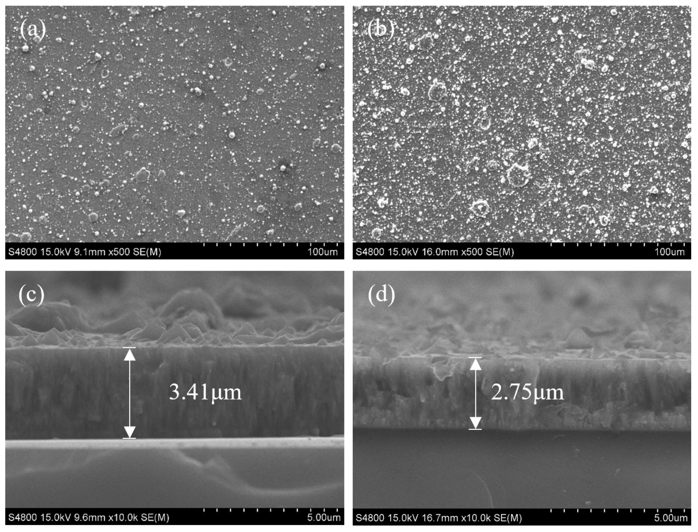
Figure 1. Scanning electron microscopy (SEM) images of the surface and cross-sectional morphologies of the (a,c) AlTiN and (b,d) AlTiMoN coatings.
Lubricants 12 00429 g001
Figure 2. Grazing incidence X-ray diffraction (GIXRD) patterns of the AlTiN and AlTiMoN coatings. (a) is the GIXRD pattern of the two coatings for phase analysis, (b) is the GIXRD pattern of the two coatings after overlapping, which is used to compare the peak positions of the (Al,Ti)N phase.
Lubricants 12 00429 g002
Figure 3. Optical micrographs of the (a) AlTiN and (b) AlTiMoN coatings after the Rockwell-C indentation tests. Red arrows indicate cracks.
Lubricants 12 00429 g003
Figure 4. Coefficient of friction dynamics of the AlTiN and AlTiMoN coatings.
Lubricants 12 00429 g004
Figure 5. SEM topography of the wear tracks of the (a) AlTiN and (b) AlTiMoN coatings.
Lubricants 12 00429 g005
Figure 6. Wear rates of the wear tracks on the AlTiN and AlTiMoN coatings. The width and depth profiles of the wear tracks on both coatings are also shown.
Lubricants 12 00429 g006
Figure 7. Schematic diagram illustrating the cutting force directions of the cutting tool.
Lubricants 12 00429 g007
Figure 8. Cutting forces on (a) the AlTiN- and (b) AlTiMoN-coated tools.
Lubricants 12 00429 g008
Table 1. Elemental composition of the AlTiN and AlTiMoN coatings (at.%).
AlTiMoN
AlTiN27.4 ± 0.915.8 ± 0.756.8 ± 1.5
AlTiMoN24.9 ± 1.014.2 ± 0.95.1 ± 0.655.8 ± 1.2
Table 2. H and E of the AlTiN and AlTiMoN coatings.
CoatingHardness (GPa)Elastic Moduli (GPa)H/EH3/E2
AlTiN26 ± 2318 ± 90.0820.174
AlTiMoN30 ± 3341 ± 120.0880.232
Table 3. Elemental composition of the wear tracks of the AlTiN and AlTiMoN coatings (at.%).
AlTiMoNWCCo
AlTiN36.1 ± 0.861.3 ± 1.32.6 ± 0.7
AlTiMoN23.1 ± 0.614.8 ± 0.55.1 ± 0.557.0 ± 1.2
Table 4. Cutting temperatures of the AlTiN- and AlTiMoN-coated tools.
Highest Temperature During Cutting (°C)Average Temperature at Which Cutting Is Stable (°C)
AlTiN611596
AlTiMoN577560
Disclaimer/Publisher’s Note: The statements, opinions and data contained in all publications are solely those of the individual author(s) and contributor(s) and not of MDPI and/or the editor(s). MDPI and/or the editor(s) disclaim responsibility for any injury to people or property resulting from any ideas, methods, instructions or products referred to in the content.