Article

Investigation of Effect of Surface Modification by Electropolishing on Tribological Behaviour of Worm Gear Pairs

Faculty of Mechanical Engineering and Naval Architecture, University of Zagreb, Ivana Lučića 5, 10000 Zagreb, Croatia
*
Author to whom correspondence should be addressed.
Lubricants 2024, 12(12), 408; https://doi.org/10.3390/lubricants12120408
Submission received: 15 October 2024 / Revised: 3 November 2024 / Accepted: 21 November 2024 / Published: 24 November 2024
(This article belongs to the Special Issue Mechanical Tribology and Surface Technology)

Abstract

Electropolishing using a high-current density results in a pitting phenomenon, producing a surface texture distinguished by many pits. Apart from the change in surface topography, electropolishing forms an oxide surface layer characterized by beneficial tribological properties. This paper introduces surface texturing in worm gear pairs by electropolishing a 16MnCr5 steel worm surface. Electropolishing produces surface pits 1 μm to 5 μm deep and 20 to 100 μm in diameter. The material characterization of 16MnCr5 steel is compared against the electropolished 16MnCr5 steel based on microstructure, hardness, surface topography and chemical composition. Experimental tests with worm pairs employing electropolished worms are conducted, and the results are compared to conventional worm pairs with ground steel worms. Electropolished worms show up to 5.2% higher efficiency ratings than ground ones and contribute to better running-in of worm gear pairs. Moreover, electropolished worms can reliably support full contact patterns and prevent scuffing due to improved lubrication conditions resulting from the produced surface texture and oxide surface layer. Based on the obtained results, electropolishing presents a promising method for surface texturing and modification in machine elements characterized by highly loaded non-conformal contacts and complex geometry.

1. Introduction

The worm gear pair typically comprises a steel worm as the driving member and a bronze worm wheel as the driven member. Worm gear pairs are often used in power transmission applications due to their high transmission ratios in a compact design, heavy shock loading capability, and ability to self-lock and reduce noise and vibration due to the dominant sliding motion. On the other hand, some disadvantages derive from the worm gear pair’s geometry and working principle: lower efficiency compared to other gear types, high sensitivity to assembly and manufacturing errors, and frictional heat generation paired with unfavourable lubrication conditions [1,2,3,4]. The latter is a frequent research topic since lubrication conditions are directly related to worm gear pair efficiency and overall life span. Relatively unfavourable oil entraining geometry of most common worm gear designs limits film-forming ability, load capacity, and efficiency compared to other gear types. These limitations can lead to a contact separated into two parts with contact temperatures in the middle of the contact zone being substantially higher than temperatures at the outer regions of the worm wheel tooth flank. Consequently, these temperature differences cause oil film thinning or even lubrication breakdown [5,6,7].
Researchers investigated new material pairs to improve lubrication conditions in worm gear pairs. Benedetti et al. [8] investigated steel–steel tribo-pairs with different coatings. Coated steel surfaces showed higher wear resistance compared to bronze, which is conventionally used as a worm wheel material. Fontanari et al. [9,10] studied wear damage mechanisms in steel–bronze and alloy steel–cast iron pairs under a mixed lubrication regime. Cast iron showed a lower wear rate, indicating that alternative worm wheel materials may perform better than bronze. Mašović et al. [11] investigated electropolished steel–bronze pairs. Electropolishing created surface texture with many pits/dimples, improving the lubrication and reducing friction by up to 30%. Furthermore, several studies comparing lubricating oils were conducted. The general conclusion was that mineral oils result in approximately 3–5% lower efficiency than synthetic oils [12,13]. Lastly, some researchers have investigated new geometry types on a theoretical level. Such geometries are usually characterized by improved load-carrying capabilities that should improve lubricating conditions in worm gear pairs [14,15,16].
Surface or material modification is commonly employed to improve the lubrication conditions and tribological performance of contacting surfaces of machine elements [17,18]. Typically, surfaces are modified by altering surface topography through surface texturing or employing surface coatings. Surface texturing produces surface micro-cavities with several beneficial functions: entrapment of wear debris, secondary lubrication, friction and wear reduction, and increased oil film thickness [17]. Applying surface texturing in gears is challenging due to their complex geometry, narrow tolerances, high loads accompanied by non-conformal contacts, and strict surface roughness requirements. Therefore, a conventional approach for improving lubrication conditions in gears is primarily surface grinding or superfinishing [19]. Nonetheless, some studies focused on the surface texturing of gears or gear steel. Gupta et al. used chemical etching and laser texturing on spur gear tooth flanks to produce a dimpled surface [20,21]. Such gears presented reduced wear and a decrease in vibrations. Petare et al. [22] laser-textured helical and straight bevel gears. The findings indicated higher wear resistance and increased microhardness compared to untextured gears. Nakatsuji and Mori [23,24] applied electropolishing to medium carbon steel gears. The produced surfaces were characterized by pits and micropores with oxidized and phosphoric surface compounds. The benefits of such surfaces were evident in the better oil film creation which improved pitting and scuffing durability. Li et al. [25] shot peened specimens made of gear steel, thus producing a dimpled surface with friction-reduction properties.
Based on the literature overview, various studies were conducted to improve lubrication conditions in worm gear pairs, as well as to apply surface texturing in other types of gears. However, surface modification in the form of surface texturing in worm gear pairs has not yet been attempted. This paper investigates the tribological behaviour of steel–bronze worm gear pairs employing surface-modified steel worms by electropolishing. The work conducted in this paper is based on the results of electropolished steel–bronze sliding tests presented in earlier research conducted by the authors [11]. The effects of electropolishing on surface topography, material hardness, microstructure, and chemical composition are presented and discussed. Worm gear pairs employing electropolished steel worms are compared to a conventional worm gear pairs with ground steel worms. Obtained benefits regarding better worm gear pair efficiency and operational characteristics suggest that electropolishing can be a promising surface modification method for non-conformal worm pair contact characterized by unfavourable lubrication conditions.

2. Materials and Methods

2.1. Materials

Investigated worm gear pairs comprise case-hardened 16MnCr5 steel worms and CuSn12 worm wheels, which are also considered reference materials for worm pairs by the ISO/TS 14521 standard [26]. The 16MnCr5 steel was supplied in hot-rolled round bars while the CuSn12 bronze was centrifugally cast. The chemical composition (wt.%) of the materials is presented in Table 1. Since this research focuses primarily on surface modification of 16MnCr5 steel, the properties of 16MnCr5 are covered in more detail. The microstructure of the case-hardened 16MnCr5 steel worm is presented in Figure 1. The specimens were ground (1200 grit sandpaper), polished, and etched with 3% nital for 20 seconds before images were taken using an optical microscope. The 16MnCr5 steel specimen surface shows fine martensite, while the core shows low-carbon martensite at 200× magnification. Additional analyses of 16MnCr5 steel were conducted using a scanning electron microscope (SEM-Tescan Vega 3 Easyprobe, from Tescan, Brno, Czech Republic) and by employing energy dispersive spectroscopy (EDS-Bruker B-Quantax EDS Detector, from Bruker, Karlsruhe, Germany). The details of these analyses are presented in the “Results” section.

2.2. Electropolishing Setup

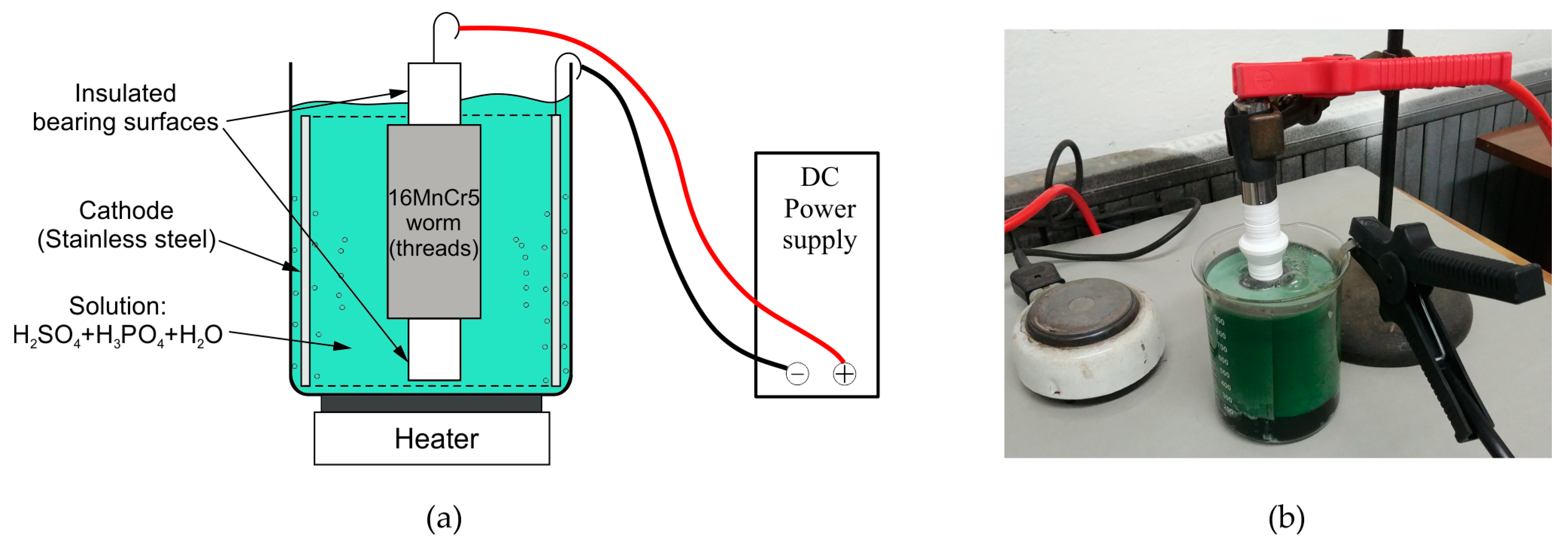
The surface of 16MnCr5 steel worms was modified via electropolishing. The same electropolishing solution and similar setup were already successfully employed in our previous work [11]. Before electropolishing, the steel worms were cleaned in an ultrasonic bath with ethanol (96%) for 10 min. The electropolishing solution was a mixture of 34% sulphuric acid, 42% phosphoric acid, and 24% water [27]. The solution was heated at 50 ± 2 °C without agitation using a Končar flask heater (Končar, Zagreb, Croatia). After electropolishing, the steel worms were rinsed and dried. The cathode, in the form of a cylindrical shell, was made of AISI 304 stainless steel. The distance between the worm and the cathode was approximately 3 cm. The bearing surfaces of the worm shaft should not be electropolished. Therefore, they were insulated using polytetrafluorethylene (PTFE) tape (Figure 2). Electropolishing parameters are provided in Table 2. It should be noted that the abbreviation “EP” will be used for the remainder of the paper to distinguish electropolished from conventional ground-only worms.

2.3. Worm Pair Experimental Testing

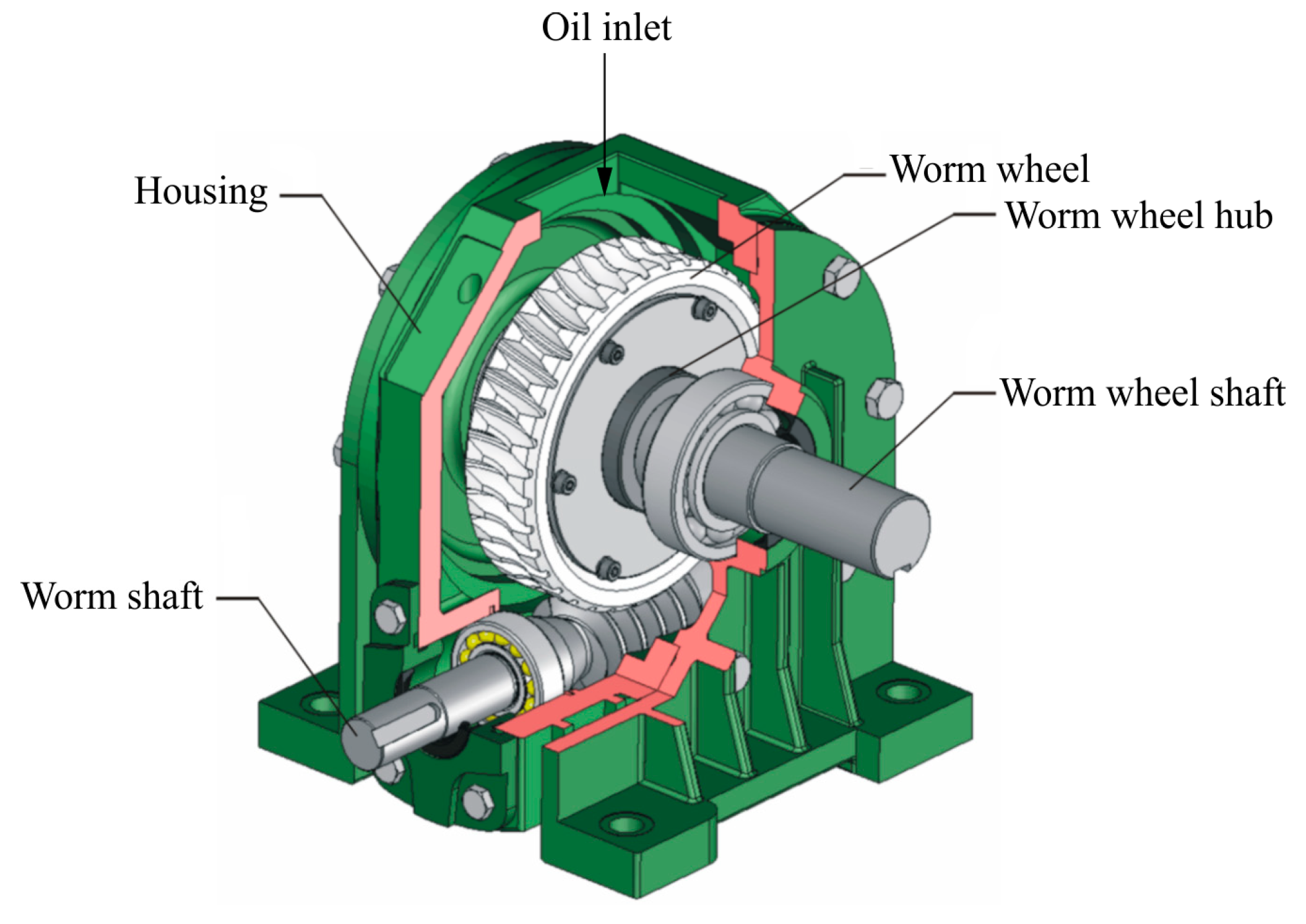
Tested worm pairs were a part of a commercially available gearbox (Figure 3). Rolling bearings were used for worm and worm wheel shafts. A new set of bearings was used for each test run. Continuous oil lubrication was supplied through the oil inlet on the top of the gearbox directly onto the worm wheel. The worm was positioned beneath the worm wheel.
The worm surface was finely ground to the average surface roughness of Ra = 0.25 μm and then electropolished to modify the surface. Bronze worm wheels were produced by the gear hobbing process without any additional surface finishing (Ra = 1.0 μm). The average surface hardness of CuSn12 bronze wheels was 110 HV. The detailed worm gear pair geometry is provided in Table 3.
The employed lubricating oil was Castrol Alpha SP 150 mineral oil. The same lubricating oil was used in the previous research conducted by the authors [11]. This oil is recommended for industrial gearboxes with forced circulation, splash, or bath lubrication. The oil contains extreme-pressure (EP) additives for good thermal and load-carrying stability. The EP additives are compatible with both ferrous and non-ferrous materials. The selected oil conforms with AGMA 9005-E02 [28] and DIN 51517-3 [29] standards. The properties of the oil are provided in Table 4.
All worm gear pairs were dimensionally inspected according to the DIN 3974 standard [30] using an ATOS optical 3D scanner. In addition, the tooth thickness of worm wheels was also measured. The accuracy of the scanner was verified by the acceptance test values based on VDI/VDE 2634 [31] provided in Table 5. Since all worms and worm wheels were produced in the same batch, the quality grades were relatively similar and are reported as average values in Table 6. Grade 1 indicates the highest accuracy and tight tolerances, whereas grade 12 indicates the lowest accuracy.
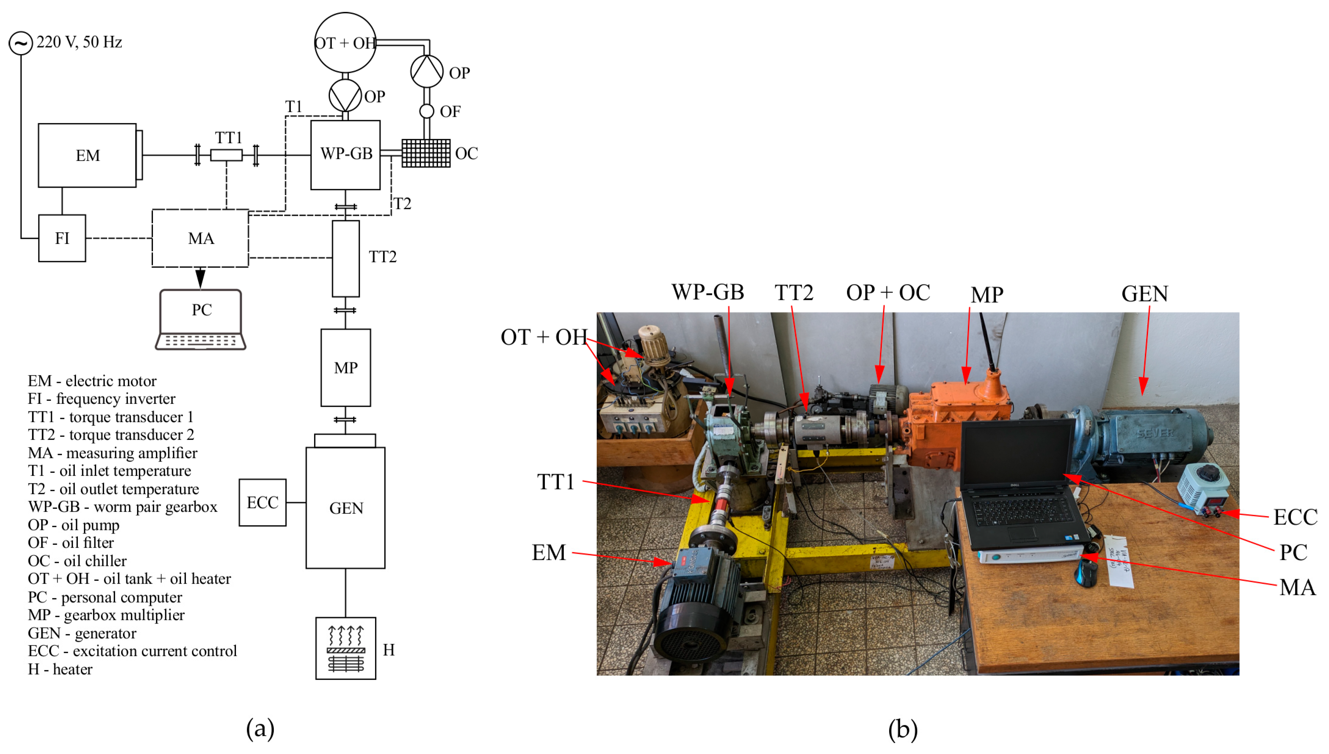
The experimental stand and a corresponding schematic representation are shown in Figure 4. A DC motor/generator (GEN) working in generator mode was used to provide the load that could be varied by the excitation current (ECC) supplied to the generator windings. The rotational speed of the driving electric motor (EM) was regulated by the frequency inverter (FI). Two shaft torque transducers (TT1 and TT2) were used to measure input and output torque from the worm pair gearbox (WP-GB). An additional gear multiplier (MP) was installed to increase the generator input shaft rotational speed. Electrical energy from the generator was supplied to electrical appliances in the test room, e.g., heaters. Oil circulation was carried out using two oil pumps (OP). The oil temperature of 60 °C was controlled by heating inside the oil tank (OT + OH) and by cooling through the oil chiller (OC). The oil was constantly filtered (OF) and fully replaced after each test run. A running-in of each worm wheel was conducted before each test run under gradually increasing load until an acceptable contact pattern was achieved.

3. Results

In this section, the effects of electropolishing on material microstructure, hardness profile, surface topography, and chemical composition of 16MnCr5 steel worms are presented and discussed, followed up with the results of worm pair experimental testing and comparison with conventional worm pairs.

3.1. Microstructure and Chemical Composition

A comparison of ground and electropolished worm microstructure and chemical composition is presented in Figure 5. According to SEM images, the material martensite microstructure remained unchanged after electropolishing, as seen in Figure 5a,b. The difference in chemical composition at the surface level was found based on EDS line analysis. In Figure 5c, the position where iron significantly reduces represents the surface of the ground worm. Other elements remained at relatively low levels, regardless of the position.
On the other hand, on the surface of the electropolished worm, the reduction of iron coincides with the increase in oxygen and silicon. The average chemical composition is provided in Table 7. The presence of oxygen can be attributed to the formation of an oxide surface layer, common in mild steel electropolishing in H2SO4 solutions [11,32,33]. An increase in silicon can be explained by the formation of a viscous salt film on the surface of the electropolished workpiece by diffusion of acceptor anions from the electrolyte or incomplete dissolution of the films produced or precipitated on the metal surface [34]. An additional reason may be found in the uneven development of crystallographic etching. Etching may be present when electropolishing conditions are employed which do not provide perfect polishing conditions.
In this research, the goal was to avoid producing a smoothened and bright surface but rather a surface texture through the pitting phenomenon. Pitting occurs when electropolishing potentials are higher than optimal for conventional electropolishing. Gas evolution occurs when oxygen bubbles are trapped on the workpiece surface. Bubbles represent a place with lower resistance where current density sharply rises, increasing the dissolution rate and consequently generating a pitting hole [35]. Another explanation for pitting can be found in the broken bubble effect. When bubbles in the viscous layer diffuse to the solution, the bubbles tend to break due to the change in surface tension between the viscous layer and the solution. Broken bubbles create a shorter path for electrical current in the viscous layer, and this effect can increase the current density by as much as two times. Consequently, higher current density within the broken bubble increases the local dissolution rate and produces the pitting hole [36].

3.2. Hardness

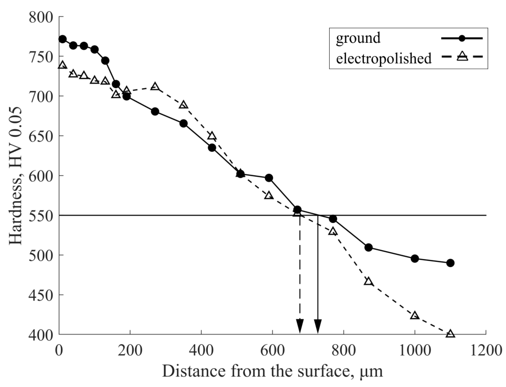
Subsurface hardness profiles of investigated ground and electropolished worms are shown in Figure 6. A worm case-hardening depth of approximately 0.7 mm (±0.03 mm) was determined according to ISO 18203 standard using a limit of 550 HV [37]. Moreover, the case-hardening depth was in accordance with the recommended values for worm module m = 4 mm [38]. Presented profiles correspond to subsurface hardness with the closest measuring point to the surface at 20 μm. A minor decline in hardness can be observed up to the depth of 150 μm. It is important to note that this measured decline in subsurface hardness is inside the measurement uncertainty of the surface hardness measuring method and therefore should not be considered evidence of reduced subsurface hardness in electropolished steel. Also, it is possible that minor microstructural differences among measured samples influenced the presented subsurface hardness values. At larger depths from the surface, the difference in hardness becomes negligible.
Additionally, surface hardness measurement of ground and electropolished worms was conducted. The results showed 870 HV for the ground and 560 HV for the electropolished surface. Additional measurements of electropolished steel worms were conducted after careful removal of the oxide surface layer using 1200-grit sanding paper to investigate the effect of the oxide surface layer on the surface hardness. The results showed a surface hardness of 848 HV. The literature also provides evidence of reduced surface hardness explained by two electropolishing effects. Since electropolishing is a material removal mechanism, a thin case-hardened surface layer of material might be removed from the surface which can affect the measured surface hardness [24]. Secondly, when electropolishing mild steel, the workpiece is passivated by the formation of an oxide and/or phosphate surface layer which is relatively softer than the base material [11,32,33]. Based on the earlier EDS analysis, the thickness of the oxide surface layer in 16MnCr5 steel worms was up to a couple of microns. The results showed that by removing the mentioned oxide surface layer, the surface hardness value of electropolished steel (848 HV) was similar to that of the ground steel (870 HV). According to the presented results, it can therefore be concluded that the formation of a soft oxide surface layer during electropolishing primarily contributes to lower values of surface hardness in electropolished 16MnCr5 steel worms.

3.3. Surface Topography

Surface profile measurements were performed using a Mitutoyo SJ-500 measuring instrument according to the ISO 4287 standard [39]. Examples of surface profiles with corresponding surface parameters of worm wheel and ground and electropolished worms are presented in Figure 7. Electropolished worms were characterized by many pits. Worm EP-1 had deeper pits (≈2–5 μm) compared to shallower pits on worm EP-2 (≈1–2 μm). This observation can be attributed to different current densities as worm EP-1 was electropolished with a current density of 20 A/dm2 compared to 15 A/dm2 employed on worm EP-2. An additional noticeable difference was found in pit diameters. Lower current density employed on worm EP-2 enlarged existing pits/valleys of ground surface that were approximately 1 μm deep, resulting in 50–100 μm pit diameters. On the other hand, pit diameters on worm EP-1 surface were in the range of 20–50 μm.
Regarding surface texture properties, the goal was to produce a surface characterized by pits and negative Rsk and higher Rku surface parameters. Pitted or dimpled surfaces are often characterized by negative Rsk and higher Rku values; such surface textures have already shown friction-reduction characteristics [11,40,41,42]. Pits (or dimples) act as oil reservoirs, providing secondary lubrication and reducing friction. Furthermore, the significant increase in Ra was aimed to be avoided because it usually results in higher friction and wear. In the presented case, the average surface roughness increased from Ra = 0.25 for ground worms to Ra ≈ 0.50 for electropolished worms. This observation results in two types of surface textures that were applied and tested on worm pairs. The first one is the electropolished worm surface (worm EP-1), which has characteristics similar to surfaces mentioned in the literature, with surface parameters Rsk = −0.996 and Rku = 7.228 and deeper but smaller pits. The second one is the electropolished worm surface (worm EP-2) with slightly different characteristics, namely Rsk = −0.008 and Rku = 3.554, but shallower and larger pits. Surface parameter values are presented in detail in Table 8.
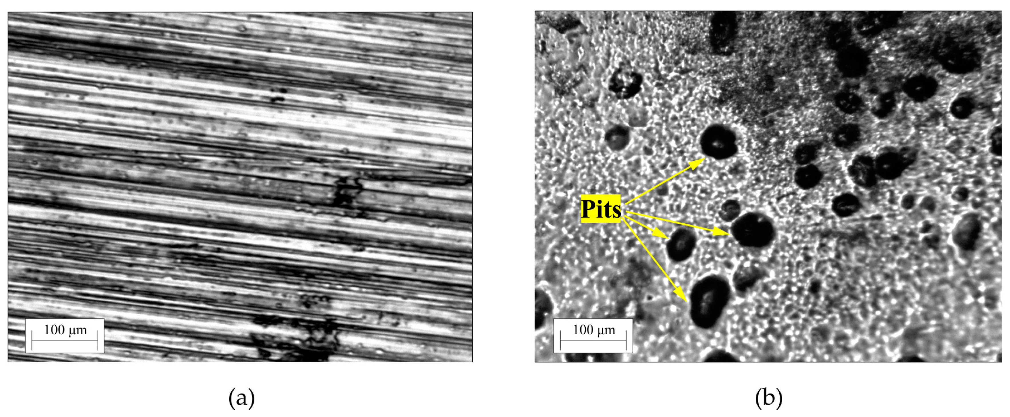
Ground and electropolished worm surfaces are shown in Figure 8. Ground worm’s surface is characterized by grinding marks, while the electropolished surface has many irregular pits/dimples distributed stochastically. The pit area density was 11% in the regions with more pits. In contrast, the pit area density in sparser regions reduced to 9% of the total surface area. In previous research [11], electropolishing 16MnCr5 steel discs with a current density of 30 A/dm2 yielded a similar albeit slightly higher pit area density of 12%. Generally, 5% to 20% pit area density was reported as beneficial regarding friction reduction [43,44,45,46,47].

3.4. Worm Gear Pair Experimental Tests

Experimental testing conditions, such as nominal rotational worm speed, nominal working load, and oil temperature, were selected to replicate realistic working conditions for employed worm gear pair geometry and materials. Also, working conditions were selected to satisfy surface durability (i.e., pitting resistance) and wear load capacity calculation procedures according to ISO/TS 14521 [26]. Tests were carried out for NL = 2∙× 106 worm wheel load cycles. Tested worm pair combinations, testing conditions, and values calculated according to ISO/TS 14521 are presented in Table 9. Worm pair designations that will be used for the remainder of this paper can be found in the rightmost column of Table 9.
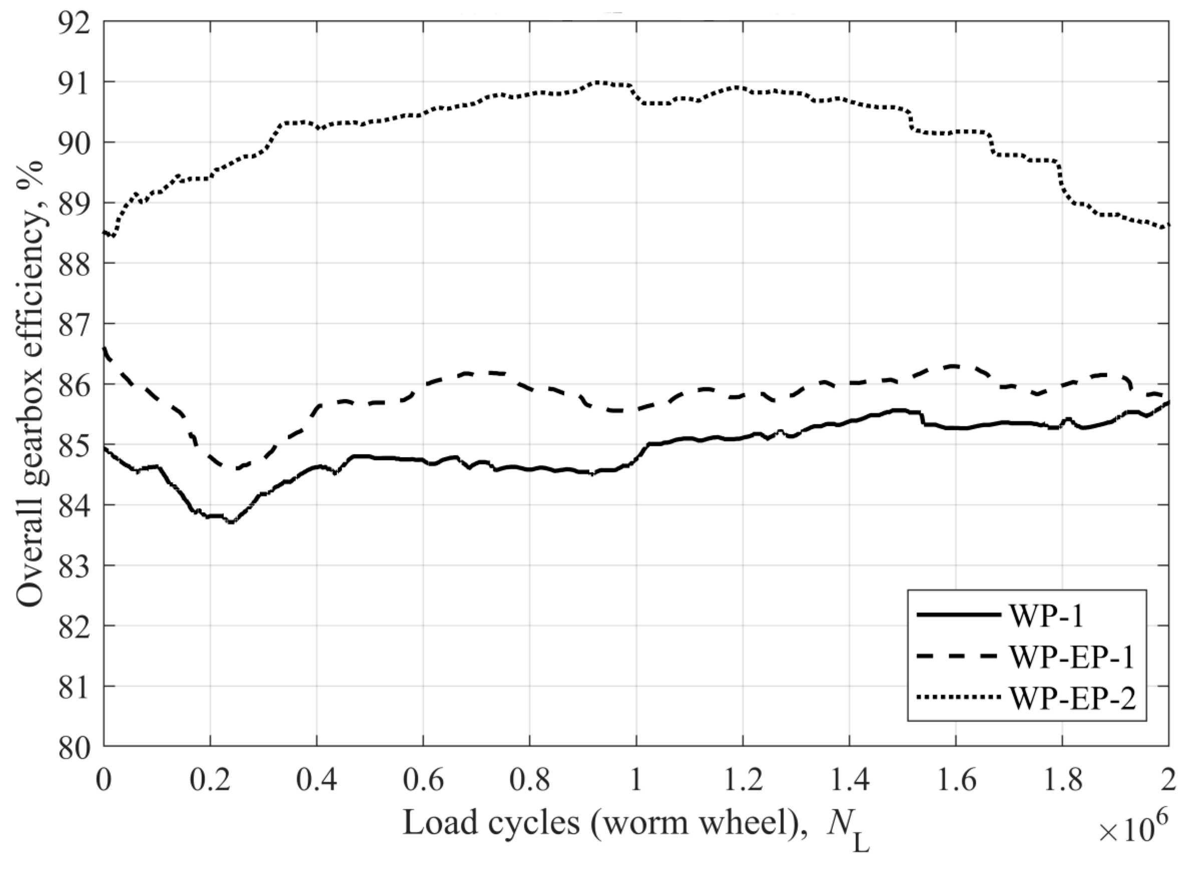
The comparison of the overall gearbox efficiency is presented in Figure 9. The average efficiencies of WP-1, WP-EP-1, and WP-EP-2 were 84.9%, 85.8%, and 90.1%, respectively. The worm gear pair WP-2 will be discussed separately due to the occurrence of scuffing. Both worm gear pairs with electropolished worms showed improved efficiencies compared to WP-1. As mentioned, the electropolished surface had many pits that had multiple functions. Pits act as oil reservoirs, providing secondary lubrication, increasing oil film thickness, and enhancing heat dissipation which is attributed to an increase in overall efficiency. Also, pits can improve the tribological behaviour of contacting surfaces by entrapping abrasive particles [48]. In the case of worm gear pairs, the latter function can be particularly useful as worm wheel wear is usually one or two orders of magnitude larger than wear in steel gears in general. This phenomenon is especially pronounced during the running-in phase and early stages of the operation.
A more noticeable increase in efficiency rating was found for WP-EP-2, where the worm surface was characterized by shallower but larger pits. The explanation for such a phenomenon lies in the geometry of the pits. In the locations of deeper pits in the contact zone, the lubricant experiences a severe decrease in pressure, leading to a lower viscosity that prevents the lubricant from completely separating the contacting surfaces [49]. Also, a countereffect of textured surfaces in non-conformal contacts (as in gears and worm pairs) can occur. An occurrence of cavitation inside deeper cavities in highly loaded non-conformal contacts can result in an increase in the coefficient of friction compared to an untextured surface [50]. On the other hand, the benefit of shallower pits can be explained by their smaller volume, which is more easily filled with oil to build additional hydrodynamic pressure and thus provide the separation of contacting surfaces [40].
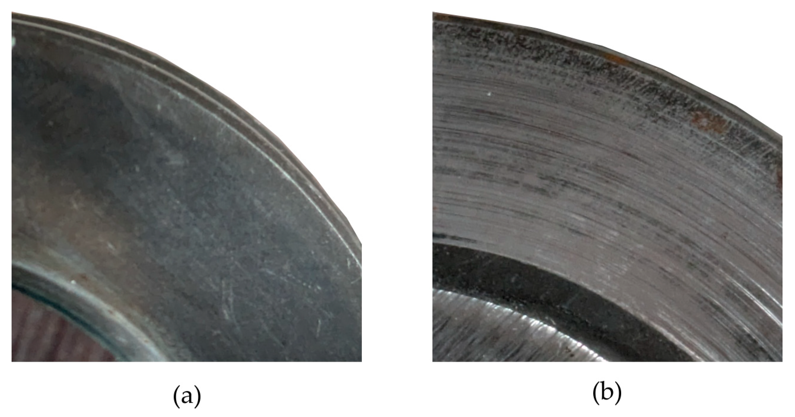
An example of surface profiles after the test is shown in Figure 10. By comparing the surface profiles of the electropolished worm before and after the test, it can be concluded that minimal to no wear occurred on the electropolished surface of the worm as its surface topography remained unchanged. The values of Ra, Rsk, and Rku were similar to those before the test (Figure 7). In addition, the surface pits produced by electropolishing did not deteriorate. The softer oxide surface layer was damaged and removed during worm gear pair operation, presumably already in the running-in phase [11,51]. The appearance of worm threads after electropolishing and after the test can be seen in Figure 11.
In contrast to conventional steel–steel gear material pairs, the steel–bronze pair favours the surface texture on a harder steel worm as most of the wear takes place on a softer bronze worm wheel. A similar finding was reported by Kasem et al. [48]. The authors suggested that surfaces textured with small and shallow dimples could reduce friction in lubricated contact with one contacting body having high wear resistance. Regardless of surface parameters used in the design of surface textures, the presented results imply that in the case of worm gear pairs, the focus should be placed primarily on the pit/dimple geometry and then complemented by surface parameters as a promising guide towards successful surface texturing application.
The additional phenomenon of electropolished steel surfaces in contact with bronze is higher bronze wear and therefore faster running-in [11]. By observing efficiency plots in Figure 9, faster running-in can be observed for WP-EP-2. At the same time, up to NL = 2.5 × 10⁵, both WP-1 and WP-EP-1 had a period of decreasing efficiency, indicating a prolonged running-in process until the steady-state running was reached at approximately NL = 4 × 10⁵. Higher wear was evident in both WP-EP-1 and WP-EP-2 compared to WP-1.
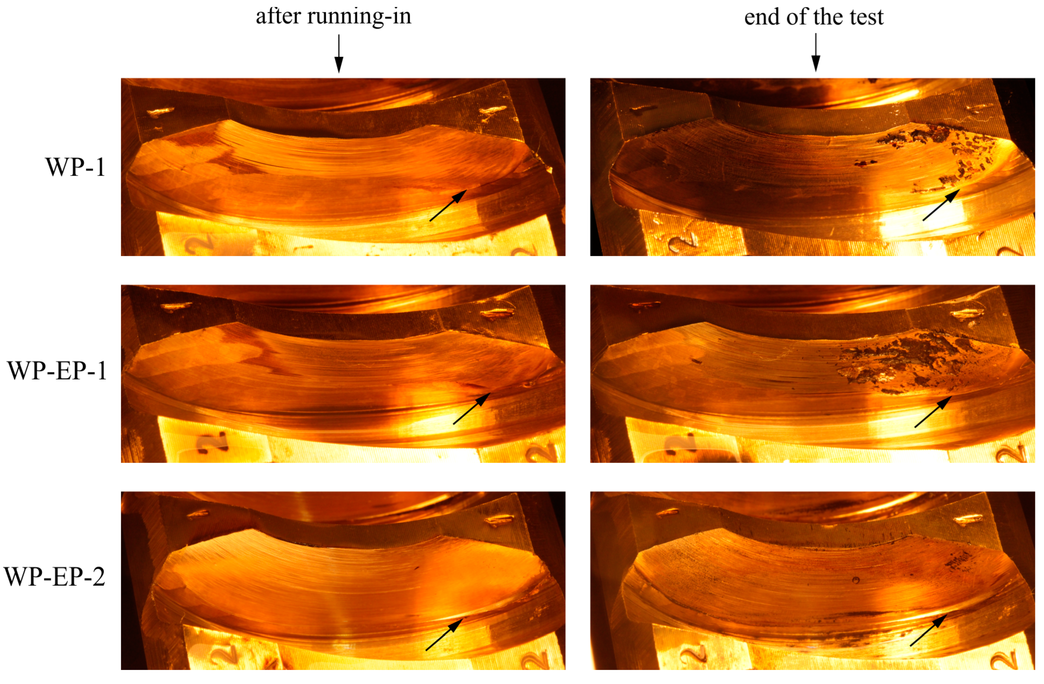
A visual representation of worm wheel wear after running-in and at the end of the test is given in Figure 12. By inspecting the lower right section of the worm wheel tooth flank, the ridge on the WP-EP-2 worm wheel is considerably larger compared to the other two worm wheels. Generally, the difference in wear between “after running-in” and “end-of-test” figures is negligible. This observation suggests that, as anticipated, most wear occurred during the running-in phase due to the nature of wear in sliding contacts [52]. The average tooth thicknesses of a worm wheel based on 36 measurements per worm wheel (z2 = 36) are shown in Table 10. Tooth thickness was measured at the middle of the flank on the worm wheel pitch diameter.
Based on the tooth thickness measurement, the worm wheel in WP-EP-2 experienced the most wear, which can be observed in Figure 12. Larger wear during the running-in phase resulted in a larger initial contact pattern than worm wheels in WP-1 and WP-EP-1. Contact patterns can be recognized by abrasive grooves in the direction of sliding and matted surface appearance.
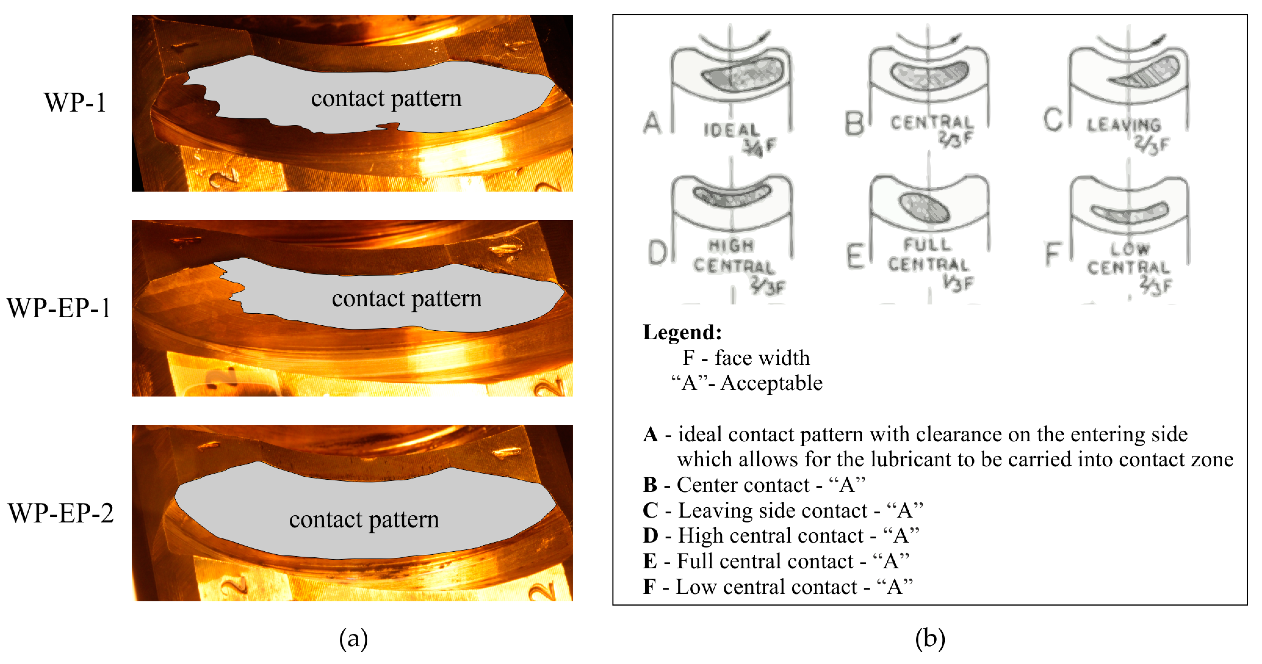
More clear representation of contact patterns can be found in Figure 13. Contact pattern adjustment in worm gear pairs is usually carried out by axial alignment of the worm wheel shaft. Larger contact patterns contribute to more uniform contact stress distribution, which can affect the uniformity and thickness of oil film. This observation also explains the difference in pitting, as the worm wheel in WP-EP-1 experienced the most pitting while having the smallest contact pattern among tested worm pairs. The relationship between contact patterns, pitting, and worm pair efficiency is relatively complex. In the case of 16MnCr5-CuSn12 worm pairs, Huber [53] concluded that neither larger contact patterns nor variation in load or pitting have an explicit or clear effect on the overall efficiency of worm gear pairs. In addition, pitting can provide additional lubrication in the contact zone as pits can act as oil reservoirs, resulting in pitted worm wheels having a similar efficiency rating to non-pitted ones [13,54].
As per Figure 13, the contact pattern established in WP-EP-2 can be considered a full contact pattern. In general, a full contact pattern in worm pairs is avoided as it limits the oil from entering the contact zone, promoting the onset of scuffing and, consequently, worm gear pair failure [55]. Instead, incomplete but acceptable contact patterns primarily positioned on the leaving side of the worm wheel tooth flank are frequently present (Figure 13). Although the full contact pattern was established in WP-EP-2, no problems with scuffing occurred. Moreover, the highest overall efficiency and lowest pitting were recorded for WP-EP-2. This finding suggests that electropolishing modifies the worm surface to provide improved or additional lubrication that can consistently and reliably support full contact patterns in worm gear pairs.
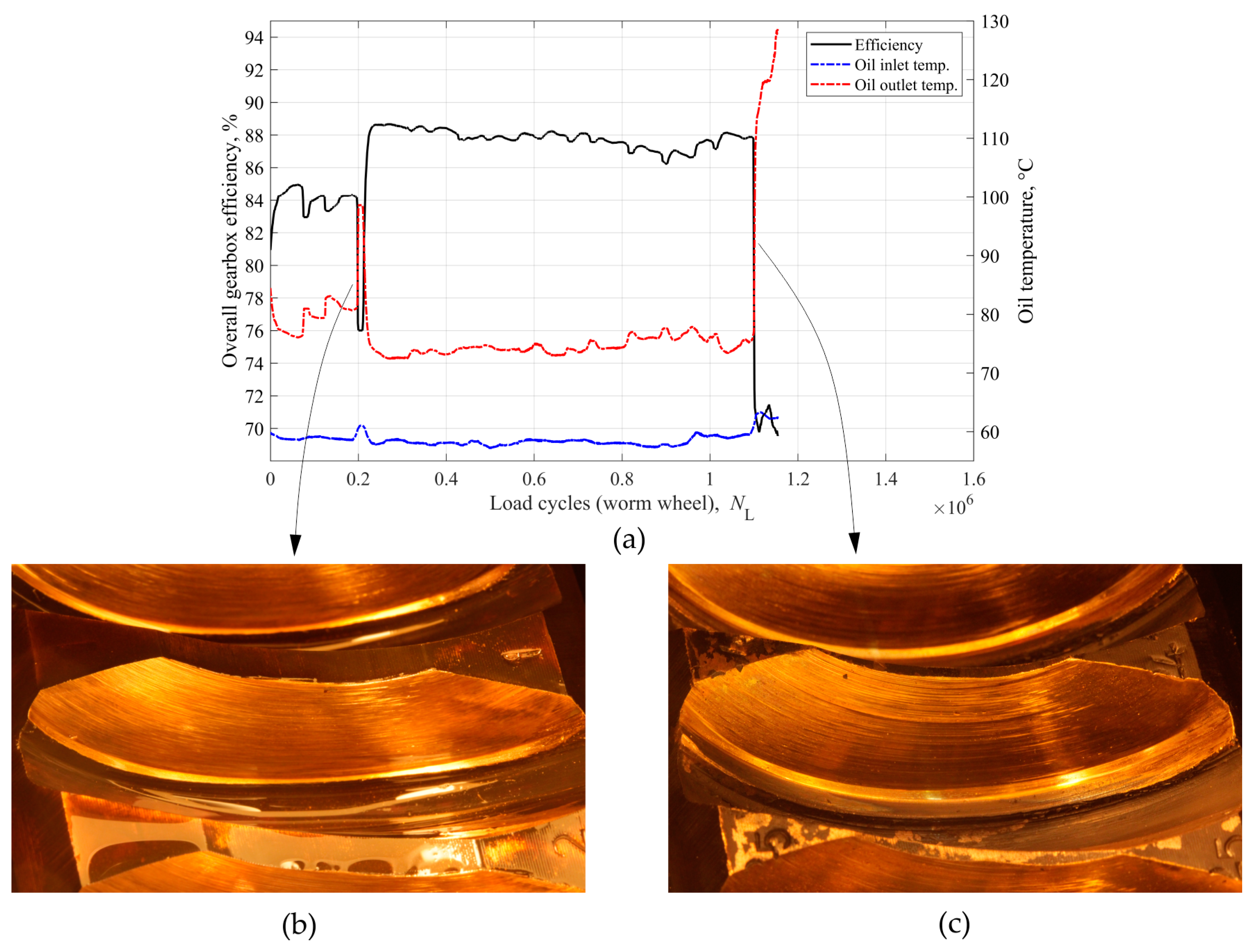
An additional test run was carried out to study the behaviour of conventional worm gear pair WP-2 under a full contact pattern. The results are presented in Figure 14. The test run ended prematurely due to two periods of intense scuffing. In worm gear pairs, scuffing occurs primarily as a consequence of improper lubricating conditions. Due to the dominant sliding motion in the mesh, the oil is constantly scrapped off from contacting surfaces. Therefore, an adequate amount of constant oil supply is necessary for worm gear pairs to function properly. When a full contact pattern is established, the contact spans across the whole worm wheel tooth flank surface, starting from entering and spreading towards the leaving side of the flank. If a contact is established on the entering side of the worm wheel tooth flank, the oil cannot properly supply the contact zone and the temperature in the contact zone will rise significantly. The rise in contact temperatures in turn reduces the oil viscosity, oil film thickness, and desorption of the lubricant from the surface. The sudden increase in heat in the contact zone leads to the micro-welding of asperities in contact. Finally, as surfaces leave the contact, the welded material is torn apart, promoting the adhesive wear of contacting surfaces.
In the example of WP-2, the first scuffing period was noticed at NL = 2 × 10⁵, while the second was observed at NL = 1.1 × 10⁶, causing worm pair failure. The overall efficiency was relatively high between the two scuffing periods, accompanied by high sliding wear. The high wear rate prevented pitting formation as the material was constantly removed from the worm wheel tooth flank. The high wear rate also sharply decreased worm wheel tooth thickness (Figure 14b). By the end of the test, worm wheel teeth were completely worn out and pointed (Figure 14c). Scuffing periods were characterized by low efficiency and a high rise in oil outlet temperature. The oil outlet temperature was approximately 74 °C in other tested worm pairs. In contrast, during two periods of severe scuffing observed in WP-2, the oil temperature was 81 °C during the first period and almost 130 °C before the test was aborted. These findings indicate that the operation of conventional worm gear pairs with an established full contact pattern is not sustainable as improper lubrication conditions can lead to the breakdown of lubrication and scuffing.
While this research focused primarily on the feasibility of surface texturing in worm gear pairs, the question of how different surface texture parameters influence the tribological behaviour of worm gear pairs remains open. Various surface textures can be produced and investigated by varying electropolishing conditions regarding overall efficiency rating and wear behaviour. The main difference and disadvantage of surface texture produced by electropolishing is its stochastic nature and inability to control the pit/dimple geometry and structure. On the other hand, electropolishing is a relatively simple, fast, and affordable process compared to other common surface texturing methods (e.g., laser surface texturing, chemical etching), especially when application on complex geometry is considered. Therefore, comparing different textures produced by electropolishing to optimize surface texture parameters for highly loaded non-conformal contacts as found in gears will be of future interest.
Furthermore, as steel worms experience little wear, there is a possibility to apply two-step electropolishing to “recycle” steel worms. Firstly, conventional electropolishing can be used to remove wear marks and then, in the second step, electropolishing with altered parameters can be employed to produce surface texture. In this way, the need for producing new worms is reduced. A potential disadvantage of this approach is the degraded dimensional accuracy of such worms as electropolishing removes surface material, leading to increased clearance and backlash in worm gear pairs. Nonetheless, this proposed approach remains open for future investigations.

4. Conclusions

In this paper, material characterization of electropolished 16MnCr5 steel was conducted, followed by an investigation of the tribological behaviour of electropolished 16MnCr5 steel worms paired with bronze CuSn12 worm wheels. The focus was on assessing efficiency rating, worm wheel wear, and surface topography. The results were compared to a conventional worm gear pair with a ground 16MnCr5 steel worm. The main results can be summarized as follows:
  • Electropolishing modifies the surface by producing surface texture and an additional oxide surface layer. Surface texture is characterized by pits 1 to 5 μm deep and 20 to 100 μm in diameter with area densities from 9% to 11%.
  • The formation of a softer oxide surface layer during electropolishing primarily contributes to lower surface hardness values in electropolished 16MnCr5 steel worms. However, no deterioration of the produced surface texture was noticed after the test runs.
  • Worm pairs employing electropolished worms showed a higher efficiency rating, up to 5.2%, compared to conventional worm gear pairs with ground worms. This phenomenon can be attributed to improved lubrication conditions due to surface pits providing additional lubrication and promoting hydrodynamic pressure build-up.
  • Improved lubrication conditions can reliably support full contact patterns and prevent scuffing in worm pairs with electropolished worms.
  • Electropolished worms result in larger worm wheel wear, which can assist in faster running-in and better contact patterns.
This research presents the initial attempt at applying and assessing the effects of surface texturing in worm pairs. As such, some challenges and questions regarding the presented work remain open. As the density and geometry of the produced pits cannot be precisely controlled, different electropolishing parameters should be investigated to achieve different pit geometry, followed by an investigation of their tribological performance. Although the literature explains several of the electropolishing effects investigated in this research, the influence of electropolishing solution on surface topography and chemical composition is not yet fully known, as mild steel is not commonly electropolished. Lastly, besides gears and highly loaded non-conformal contacts, the application of electropolishing in conformal contacts is not yet investigated and will be the aim of future work.

Author Contributions

Conceptualization, R.M., S.J. and D.Ž.; methodology, R.M., S.J. and D.Ž.; validation, R.M. and D.Ž.; formal analysis, R.M., I.Č. and D.M.; investigation, R.M., S.J. and D.Ž.; resources, S.J. and D.Ž.; data curation, R.M., I.Č. and D.M.; writing—original draft preparation, R.M.; writing—review and editing, R.M., S.J., I.Č., D.M. and D.Ž.; visualization, R.M. and S.J.; supervision, S.J. and D.Ž. All authors have read and agreed to the published version of the manuscript.

Funding

This research received no external funding.

Data Availability Statement

The data presented in this study are available on request from the corresponding author.

Conflicts of Interest

The authors declare no conflicts of interest.

References

  1. Opalić, M.; Žeželj, D.; Vučković, K. A New Method for Description of the Pitting Process on Worm Wheels Propagation. Wear 2015, 332–333, 1145–1150. [Google Scholar] [CrossRef]
  2. Crosher, W.P. Design and Application of the Worm Gear; ASME Press: New York, NY, USA, 2002; ISBN 0-7918-0178-0. [Google Scholar]
  3. Litvin, F.L.; Fuentes, A. Gear Geometry and Applied Theory, 2nd ed.; Cambridge University Press: New York, NY, USA, 2004; ISBN 978-0-511-23000-4. [Google Scholar]
  4. Razdevich, S.P. Dudley’s Handbook of Practical Gear Design and Manufacture, 3rd ed.; CRC Press: Boca Raton, FL, USA, 2016; ISBN 9781498753104. [Google Scholar]
  5. Sharif, K.J.; Kong, S.; Evans, H.P.; Snidle, R.W. Contact and Elastohydrodynamic Analysis of Worm Gears Part 1: Theoretical Formulation. Proc. Inst. Mech. Eng. Part C J. Mech. Eng. Sci. 2001, 215, 817–830. [Google Scholar] [CrossRef]
  6. Sharif, K.J.; Kong, S.; Evans, H.P.; Snidle, R.W. Contact and Elastohydrodynamic Analysis of Worm Gears Part 2: Results. Proc. Inst. Mech. Eng. Part C J. Mech. Eng. Sci. 2001, 215, 831–846. [Google Scholar] [CrossRef]
  7. Kong, S.; Sharif, K.; Evans, H.P.; Snidle, R.W. Elastohydrodynamics of a Worm Gear Contact. J. Tribol. 2001, 123, 268–275. [Google Scholar] [CrossRef][Green Version]
  8. Benedetti, M.; Fontanari, V.; Torresani, E.; Girardi, C.; Giordanino, L. Investigation of Lubricated Rolling Sliding Behaviour of WC/C, WC/C-CrN, DLC Based Coatings and Plasma Nitriding of Steel for Possible Use in Worm Gearing. Wear 2017, 378–379, 106–113. [Google Scholar] [CrossRef]
  9. Fontanari, V.; Benedetti, M.; Straffelini, G.; Girardi, C.; Giordanino, L. Tribological Behavior of the Bronze-Steel Pair for Worm Gearing. Wear 2013, 302, 1520–1527. [Google Scholar] [CrossRef]
  10. Fontanari, V.; Benedetti, M.; Girardi, C.; Giordanino, L. Investigation of the Lubricated Wear Behavior of Ductile Cast Iron and Quenched and Tempered Alloy Steel for Possible Use in Worm Gearing. Wear 2016, 350–351, 68–73. [Google Scholar] [CrossRef]
  11. Mašović, R.; Miler, D.; Čular, I.; Jakovljević, S.; Šercer, M.; Žeželj, D. The Effect of Steel Electropolishing on the Tribological Behavior of a Steel–Bronze Pair in the Mixed and Boundary Lubrication Regimes. Lubricants 2023, 11, 325. [Google Scholar] [CrossRef]
  12. Muminović, A.; Repčić, N.; Žeželj, D. The Efficiency of Worm Gears Lubricated with Oils of Mineral and Synthetic Bases. Trans. Famena 2013, 37, 65–72. [Google Scholar]
  13. Mautner, E.M.; Sigmund, W.; Stemplinger, J.P.; Stahl, K. Efficiency of Worm Gearboxes. Proc. Inst. Mech. Eng. Part C J. Mech. Eng. Sci. 2016, 230, 2952–2956. [Google Scholar] [CrossRef]
  14. Litvin, F.L.; Gonzalez-Perez, I.; Yukishima, K.; Fuentes, A.; Hayasaka, K. Design, Simulation of Meshing, and Contact Stresses for an Improved Worm Gear Drive. Mech. Mach. Theory 2007, 42, 940–959. [Google Scholar] [CrossRef]
  15. Sohn, J.; Park, N. Modified Worm Gear Hobbing for Symmetric Longitudinal Crowning in High Lead Cylindrical Worm Gear Drives. Mech. Mach. Theory 2017, 117, 133–147. [Google Scholar] [CrossRef]
  16. Simon, V.V. Characteristics of a New Type of Cylindrical Worm-Gear Drive. J. Mech. Des. 1998, 120, 139–146. [Google Scholar] [CrossRef]
  17. Rosenkranz, A.; Grützmacher, P.G.; Gachot, C.; Costa, H.L. Surface Texturing in Machine Elements—A Critical Discussion for Rolling and Sliding Contacts. Adv. Eng. Mater. 2019, 21, 1900194. [Google Scholar] [CrossRef]
  18. Todić, A.; Djordjević, M.T.; Arsić, D.; Džunić, D.; Lazić, V.; Aleksandrović, S.; Krstić, B. Influence of Vanadium Content on the Tribological Behaviour of X140CrMo12-1 Air-Hardening Steel. Trans. FAMENA 2022, 46, 15–22. [Google Scholar] [CrossRef]
  19. Britton, R.D.; Elcoate, C.D.; Alanou, M.P.; Evans, H.P.; Snidle, R.W. Effect of Surface Finish on Gear Tooth Friction. J. Tribol. 2000, 122, 354–360. [Google Scholar] [CrossRef]
  20. Gupta, N.; Tandon, N.; Pandey, R.K. An Exploration of the Performance Behaviors of Lubricated Textured and Conventional Spur Gearsets. Tribol. Int. 2018, 128, 376–385. [Google Scholar] [CrossRef]
  21. Gupta, N.; Tandon, N.; Pandey, R.K.; Vidyasagar, K.E.C.; Kalyanasundaram, D. Tribological and Vibration Studies of Textured Spur Gear Pairs under Fully Flooded and Starved Lubrication Conditions. Tribol. Trans. 2020, 63, 1103–1120. [Google Scholar] [CrossRef]
  22. Petare, A.; Deshwal, G.; Palani, I.A.; Jain, N.K. Laser Texturing of Helical and Straight Bevel Gears to Enhance Finishing Performance of AFF Process. Int. J. Adv. Manuf. Technol. 2020, 110, 2221–2238. [Google Scholar] [CrossRef]
  23. Nakatsuji, T.; Mori, A. Tribological Properties of Eiectrolytically Polished Surfaces of Carbon Steel. Tribol. Trans. 1998, 41, 179–188. [Google Scholar] [CrossRef]
  24. Nakatsuji, T.; Mori, A. Pitting Durability of Electrolytically Polished Medium Carbon Steel Gears—Succeeding Report. Tribol. Trans. 1999, 42, 393–400. [Google Scholar] [CrossRef]
  25. Li, W.; Lu, L.; Zeng, D. The Contribution of Topography Formed by Fine Particle Peening Process in Reducing Friction Coefficient of Gear Steel. Tribol. Trans. 2020, 63, 9–19. [Google Scholar] [CrossRef]
  26. ISO/TS 14521; Gear—Calculation of Load Capacity of Worm Gears. International Organization for Standardization: Geneva, Switzerland, 2020.
  27. ASTM-E1558; Standard Guide for Electrolytic Polishing of Metallographic Specimens. ASTM International: West Conshohocken, PA, USA, 1999.
  28. ANSI/AGMA 9005-E02; Industrial Gear Lubrication. American Gear Manufacturers Associations: Washington, DC, USA, 2014.
  29. DIN 5157-3; Lubricants—Lubricating oils—Part 3: Lubricating oils CLP. Minimum Requirements: Berlin, Germany, 2018.
  30. DIN 3974-1; Toleranzen Für Schneckengetriebe-Verzahnungen—Teil 1: Grundlagen. Deutsches Institut für Normung: Berlin, Germany, 1995.
  31. VDI/VDE 2634; Optical 3D-Measuring Systems—Multiple View Systems Based on Area Scanning. VDI/VDE-Gesellschaft Mess- und Automatisierungstechnik: Berlin, Germany, 2008.
  32. Gabe, D.R. Electropolishing of Mild Steel in Phosphoric and Perchloric Acid Containing Electrolytes. Corros. Sci. 1973, 13, 175–185. [Google Scholar] [CrossRef]
  33. Nakatsuji, T.; Mori, A. The Tribological Effect of Electrolytically Produced Micro-Pools and Phosphoric Compounds on Medium Carbon Steel Surfaces in Rolling—Sliding Contact. Tribol. Trans. 2001, 44, 173–178. [Google Scholar] [CrossRef]
  34. Landolt, D. Fundamental Aspects of Electropolishing. Electrochim. Acta 1987, 32, 1–11. [Google Scholar] [CrossRef]
  35. Han, W.; Fang, F. Fundamental Aspects and Recent Developments in Electropolishing. Int. J. Mach. Tools Manuf. 2019, 139, 1–23. [Google Scholar] [CrossRef]
  36. Lee, S.J.; Chen, Y.H.; Hung, J.C. The Investigation of Surface Morphology Forming Mechanisms in Electropolishing Process. Int. J. Electrochem. Sci. 2012, 7, 12495–12506. [Google Scholar] [CrossRef]
  37. ISO 18203; Steel—Determination of the Thickness of Surface-Hardened Layers. International Organization for Standardization: Geneve, Switzerland, 2016.
  38. Errichello, R.; Milburn, A. Optimum Carburized and Hardened Case Depth. Gear Technol. January/Febr. 2020, 58–65. [Google Scholar]
  39. ISO 4287:1997; Geometrical Product Specifications (GPS)—Surface Texture: Profile Method—Terms, Definitions and Surface Texture Parameters. International Organization for Standardization: Geneva, Switzerland, 1997.
  40. Sedlaček, M.; Gregorčič, P.; Podgornik, B. Use of the Roughness Parameters S Sk and S Ku to Control Friction—A Method for Designing Surface Texturing. Tribol. Trans. 2017, 60, 260–266. [Google Scholar] [CrossRef]
  41. Sedlaček, M.; Podgornik, B.; Vižintin, J. Planning Surface Texturing for Reduced Friction in Lubricated Sliding Using Surface Roughness Parameters Skewness and Kurtosis. Proc. Inst. Mech. Eng. Part J J. Eng. Tribol. 2012, 226, 661–667. [Google Scholar] [CrossRef]
  42. Akamatsu, Y.; Tsushima, N.; Goto, T.; Hibi, K. Influence of Surface Roughness Skewness on Rolling Contact Fatigue Life. Tribol. Trans. 1992, 35, 745–750. [Google Scholar] [CrossRef]
  43. Yue, H.; Schneider, J.; Deng, J. Laser Surface Texturing for Ground Surface: Frictional Effect of Plateau Roughness and Surface Textures under Oil Lubrication. Lubricants 2024, 12, 22. [Google Scholar] [CrossRef]
  44. Schneider, J.; Braun, D.; Greiner, C. Laser Textured Surfaces for Mixed Lubrication: Influence of Aspect Ratio, Textured Area and Dimple Arrangement. Lubricants 2017, 5, 32. [Google Scholar] [CrossRef]
  45. Ali, S.; Kurniawan, R.; Moran, X.; Ahmed, F.; Danish, M.; Aslantas, K. Effect of Micro-Dimple Geometry on the Tribological Characteristics of Textured Surfaces. Lubricants 2022, 10, 328. [Google Scholar] [CrossRef]
  46. Ghaei, A.; Khosravi, M.; Badrossamay, M.; Ghadbeigi, H. Micro-Dimple Rolling Operation of Metallic Surfaces. Int. J. Adv. Manuf. Technol. 2017, 93, 3749–3758. [Google Scholar] [CrossRef]
  47. Ronen, A.; Etsion, I.; Kligerman, Y. Friction-Reducing Surface-Texturing in Reciprocating Automotive Components. Tribol. Trans. 2001, 44, 359–366. [Google Scholar] [CrossRef]
  48. Zhang, H.; Pei, X.; Jiang, X. Anti-Wear Property of Laser Textured 42CrMo Steel Surface. Lubricants 2023, 11, 353. [Google Scholar] [CrossRef]
  49. Mourier, L.; Mazuyer, D.; Ninove, F.-P.; Lubrecht, A.A. Lubrication Mechanisms with Laser-Surface-Textured Surfaces in Elastohydrodynamic Regime. Proc. Inst. Mech. Eng. Part J J. Eng. Tribol. 2010, 224, 697–711. [Google Scholar] [CrossRef]
  50. Rosenkranz, A.; Szurdak, A.; Gachot, C.; Hirt, G.; Mücklich, F. Friction Reduction under Mixed and Full Film EHL Induced by Hot Micro-Coined Surface Patterns. Tribol. Int. 2016, 95, 290–297. [Google Scholar] [CrossRef]
  51. Ueda, M.; Spikes, H.; Kadiric, A. Influence of Black Oxide Coating on Micropitting and ZDDP Tribofilm Formation. Tribol. Trans. 2022, 65, 242–259. [Google Scholar] [CrossRef]
  52. Khonsari, M.M.; Ghatrehsamani, S.; Akbarzadeh, S. On the Running-in Nature of Metallic Tribo-Components: A Review. Wear 2021, 474–475, 203871. [Google Scholar] [CrossRef]
  53. Huber, G. Untersuchungen Über Flankentragfähigkeit Und Wirkungsgrad von Zylinderschneckengetrieben (Evolventenschnecken); TU München: Munich, Germany, 1978. [Google Scholar]
  54. Sievers, B.; Gerke, L.; Predki, W.; Pohl, M. Verschleiß- Und Grübchen Tragfähigkeit von Bronze- Schneckenrädern. Giesserei 2011, 98, 36–45. [Google Scholar]
  55. Janninck, W. Contact Surface Topology of Worm Gear Teeth. Gear Technol. March/April 1988, 31–47. [Google Scholar]
Figure 1. Microstructure and hardness of a 16MnCr5 worm: (a) core (200×); (b) case-hardened surface layer (200×).
Lubricants 12 00408 g001
Figure 2. Electropolishing setup of a steel worm: (a) schematic; (b) actual image.
Lubricants 12 00408 g002
Figure 3. CAD model of the gearbox.
Lubricants 12 00408 g003
Figure 4. Worm pair experimental setup: (a) schematic representation; (b) experimental stand.
Lubricants 12 00408 g004
Figure 5. Microstructure and chemical composition of a steel worm: (a) SEM of a ground worm cross-section; (b) SEM of an electropolished worm cross-section; (c) EDS line analysis of a ground worm; (d) EDS line analysis of an electropolished worm.
Lubricants 12 00408 g005
Figure 6. Hardness profiles of investigated ground and electropolished worms.
Lubricants 12 00408 g006
Figure 7. Surface profiles: (a) worm wheel; (b) ground worm; (c) worm EP-1; (d) worm EP-2.
Lubricants 12 00408 g007
Figure 8. Worm surface: (a) ground worm; (b) worm EP-2.
Lubricants 12 00408 g008
Figure 9. Comparison of worm gearbox efficiency.
Lubricants 12 00408 g009
Figure 10. Surface profiles of worm pair after the test: (a) worm wheel; (b) electropolished worm.
Lubricants 12 00408 g010
Figure 11. Worm surface: (a) after electropolishing; (b) after the test.
Lubricants 12 00408 g011
Figure 12. Worm wheel wear after the running-in phase and at the end of the test.
Lubricants 12 00408 g012
Figure 13. Worm wheel contact patterns: (a) tested worm wheels; (b) acceptable contact patterns according to [55].
Lubricants 12 00408 g013
Figure 14. Scuffing of worm pair WP-2: (a) efficiency and oil temperatures; (b) worm wheel tooth flank wear at NL = 2 × 10⁵; (c) worm wheel tooth flank wear at NL = 1.1 × 10⁶.
Lubricants 12 00408 g014
Table 1. Chemical composition of the materials, wt.%.
16MnCr5FeCSiMnPSCrNiMoAsAlCu
97.050.190.311.110.0180.011.010.080.010.0340.0330.15
CuSn12CuZnSCoCrPbSnNiSi---
86.150. 360.140.080.080.6712.100.40.2---
Table 2. Electropolishing parameters for 16MnCr5 steel worms.
Potential (V)Current Density (A/dm2)Time (min)
Worm EP-16.1205
Worm EP-24.7155
Table 3. Worm pair geometry.
WormWorm Wheel
Number of threads, z1 (-)2Number of teeth, z2 (-)36
Thread directionrightThread directionright
Module, m (mm)4Module, m (mm)4
Pitch diameter, dw1 (mm)36Pitch diameter, dw2 (mm)144
Pressure angle, α (°)20°Pitch, p (mm)12.566
Axial pitch, px (mm)12.566Reference diameter, dw2 (mm)144
Lead, P (mm)25.132Profile shift, x2∙m (mm)0
Lead angle, γm1, (°)12.529°
Tooth thickness, sm1 (mm)6.134
Center distance, a (mm)90
Profile typeZN
Table 4. Main properties of the Alpha SP150 lubricating oil.
Density at 20 °C (kg/m3)Kinematic Viscosity (mm2/s)Viscosity Index (-)Open Flash Point (°C)Pour Point (°C)
89040 °C100 °C>95223−21
15014.5
Table 5. Acceptance test values for ATOS 5 400 MV 320.
ParameterMaximum Deviation (mm)Allowable Limit (mm)
Probing error form (sigma)0.0010.004
Probing error (size)0.0040.015
Sphere spacing error−0.0080.012
Length measurement error−0.0060.027
Table 6. Quality grades.
DeviationWormWheel
Single pitch deviation (axial)fpx9--
Single pitch deviation--fp211
Adjacent pitch differencefux3fu211
Total pitch deviationFpz9--
Total cumulative pitch deviation--Fp29
Total profile deviationFα111Fα212
RunoutFr12Fr212
Table 7. EDS line analysis of ground and electropolished worm, wt.%.
ElementFeOPSSiCaMnCrC
Ground worm97.24-0.010.010.230.021.381.11-
Electropolished worm92.693.520.020.031.250.071.271.15-
Table 8. Average values of surface parameters for worm wheels, ground, and electropolished worms.
Ra (μm)Rq (μm)RskRkuRk (μm)Rpk (μm)Rvk (μm)
Worm wheel1.091.350.632.823.371.431.14
Ground worm 0.250.33−1.0517.680.740.170.45
Worm EP-10.550.77−0.997.231.430.481.54
Worm EP-20.480.60.013.551.530.400.90
Table 9. Tested worm pair combinations and testing conditions.
Worm MaterialWorm Wheel MaterialDesignation
16MnCr5, groundCuSn12WP-1
16MnCr5, groundCuSn12WP-2 *
16MnCr5, ground and electropolishedCuSn12WP-EP-1
16MnCr5, ground and electropolishedCuSn12WP-EP-2
Nominal worm shaft speed1480 rpm
Worm wheel nominal load, T2300 Nm
Oil inlet temperature60 °C
Worm wheel load cycles, NL2 × 106
Mean contact stress, σHm323 N/mm2
Limiting contact stress, σHG415 N/mm2
Pitting resistance-safety factor, SH1.285
Worm wheel tooth flank loss, δWn0.517 mm
Limiting value of tooth flank loss, δWlim,n1.171 mm
Wear load capacity-safety factor, SW2.265
* Occurrence of scuffing.
Table 10. Average worm wheel tooth thickness before and after the test.
Tooth Thickness, sm2Before the Test, mmEnd of the Test, mmDifference, mm
WP-16.1506.0990.051
WP-EP-16.1746.1070.067
WP-EP-26.0865.8320.254
Disclaimer/Publisher’s Note: The statements, opinions and data contained in all publications are solely those of the individual author(s) and contributor(s) and not of MDPI and/or the editor(s). MDPI and/or the editor(s) disclaim responsibility for any injury to people or property resulting from any ideas, methods, instructions or products referred to in the content.