Article

Study on Performance of Compliant Foil Gas Film Seal Based on Different Texture Bottom Designs

1
Aeronautical Engineering Institute, Civil Aviation University of China, Tianjin 300300, China
2
Aeronautical Mechanical and Electrical Engineering Institute, Chongqing Aerospace Polytechnic, Chongqing 400021, China
3
AECC Hunan Aviation Powerplant Research Institute, Zhuzhou 412002, China
4
Safety Science and Engineering Institute, Civil Aviation University of China, Tianjin 300300, China
5
Science and Technology on Helicopter Transmission Laboratory, Zhuzhou 412002, China
6
Sino-European Institute of Aviation Engineering, Civil Aviation University of China, Tianjin 300300, China
*
Author to whom correspondence should be addressed.
Lubricants 2024, 12(12), 445; https://doi.org/10.3390/lubricants12120445 (registering DOI)
Submission received: 18 November 2024 / Revised: 1 December 2024 / Accepted: 6 December 2024 / Published: 12 December 2024
(This article belongs to the Special Issue Mechanical Tribology and Surface Technology, 2nd Edition)

Abstract

:
To investigate how texture affects the sealing performance of compliant foil, a systematic analysis was conducted on the impact of various bottom shapes of rectangular textures on the gas film sealing performance of the foil. The Reynolds equation for the compliant foil seal is solved using the finite difference method., and the average gas film pressure, bearing capacity, leakage, and friction performance parameters of the compliant foil gas film seal are obtained. The results indicate that the convergent right triangle bottom shape texture provides the best sealing performance, with the average gas film pressure reaching 1.457. This is 0.10% higher than the non-textured case and 0.55% higher than the horizontal bottom shape texture. For the same texture area ratio, increasing the texture length in the axial direction improves the dynamic pressure effect. When the aspect ratio is 2/1, the gas film pressure reaches its maximum, and leakage is minimized. With an area ratio of 0.25 and a depth of 5 μm, the compliant foil gas film seal achieves the highest pressure and the lowest leakage. Compared with the average pressure without texture, the average pressure can be increased by 0.83%, and the leakage can be reduced by 6.61%.

1. Introduction

As a new type of non-contact sealing technology for aero-engines [1], compliant foil gas film seal is a kind of sealing structure composed of smooth elastic flat foil and rigid arch foil, which can operate reliably under large rotor offset. It demonstrates low power consumption, minimal wear, and high sealing efficiency, making it suitable for the technical demands of modern high-end rotating machinery [2]. Heshmat et al. [3] showed through experiments that this kind of structure using the dynamic pressure effect to form a rigid gas film to reduce the leakage of the seal is extremely low and shows a wide range of applications. Xu et al. [4] studied the gas film pressure distribution characteristics of bump foil journal bearings and developed a gas film thickness model that accounts for eccentricity, gas compressibility, and foil deformation. Ma et al. [5] studied the quasi-dynamic characteristics of the compliant support floating ring cylindrical gas film seal, offering a theoretical foundation for the design of sealing systems. Lee et al. [6] analyzed the effect of Coulomb friction on the static performance of foil journal bearings and found that compliant foil can adaptively deform under load, absorb unsteady displacement changes through its own deformation, and automatically adjust the balance relationship between the rotor, gas film, and sealing surface to prevent contact friction and collision. At the same time, it also reduces the accuracy of manufacturing and installation and improves the overall inclusiveness.
On this basis, Sun [7] studied the influence of operating and structural parameters on the steady-state characteristics of the compliant support. The findings indicate that as the film thickness increases, the average equivalent stress of the compliant support first decreases and then stabilizes. Jiang et al. [8] studied the parameters of the compliant end face gas film seal, taking into account the slip flow effect. They found that changes in seal structure parameters significantly affect sealing performance. As foil thickness increases, the compliant end face behaves more like a rigid one, weakening the fluid wedge effect and reducing both the gas film opening force and mass leakage rate. Wang et al. [9] investigated the steady-state performance of the compliant foil gas seal, predicted its sealing efficiency, and obtained the pressure distribution in the compressible flow field. They also used the finite difference method to analyze the impact of operating parameters on the rotor dynamic coefficient. Wang et al. [10] analyzed the dynamic performance of compliant foil gas seals with varying structural parameters and found that the compliant structure enhances sealing performance compared to the rigid gas film. Thus, the compliant foil gas seal is highly valuable for improving the dynamic performance of rotating equipment.
To enhance the sealing performance of compliant foils and minimize friction and wear, surface texture technology is used to optimize interface modeling as an effective means to improve tribological characteristics. Hamilont et al. [11] proposed the idea of using surface micro-protrusions to generate additional hydrodynamic lubrication effects. Luz [12] studied the lubrication effect of surface texture in the cylinder and found that the increase in texture area can reduce the overall friction coefficient. Shi et al. [13,14] considered the collective effect of adjacent textures on the textured surface and examined how microgrooves and micropits influence mechanical seal performance. Lu [15] analyzed the anti-friction effect of square micro-texture under lubrication, indicating that micro-texture can greatly lower the friction coefficient. Pei et al. [16] studied the effect of surface texture on the lubrication performance of floating ring bearings and found that while surface texture improves bearing performance and lowers oil film temperature, it also increases total power loss. Based on three types of texture distribution, Zhang et al. [17] investigated how micro-texture depth and configuration affect bearing capacity, finding that an optimal micro-texture configuration can boost the bearing capacity of gas foil bearings by over 10%. Wang et al. [18] explored the impact of rectangular texture orientation on floating ring seal performance, showing that selecting the optimal texture angle can enhance the performance of floating ring gas film seals.
Nowadays, surface texture technology has currently been applied to compliant foil seals. Xu et al. [19,20] compared six typical cavity shapes, showing that the inverted triangle cavity helps control mass leakage rate and enhances stability, resulting in optimal overall sealing performance. Vishal [21] analyzed the tribological properties of foil bearings with micro-holes and found that increasing the depth can reduce the friction coefficient. However, limited research has been conducted on enhancing gas film sealing performance through the design of surface texture bottom shapes. The existing textured structure of the compliant foil seal is also relatively simple. Lu et al. [22] analyzed the tribological properties of the triangular inclined bottom shape, indicating that the fluid pressure generated by the wedge space created by the inclined bottom of the texture contributes to the overall directional friction effect. Nanbu [23] examined the impact of texture bottom shape and relative surface motion on lubrication performance, indicating that the wedge and step bottom morphology can produce thicker oil film. Therefore, the study of the textured bottom shape can offer valuable insights for optimizing the design of textured gas film seals.
In summary, studying the configuration, shape, area ratio, depth, and bottom shape of textures is crucial for optimizing the gas dynamic pressure effect in rotating machinery and enhancing gas film sealing performance. This study focuses on the cylindrical gas film seal of compliant foil as the research subject. The finite difference method (FDM) and the Newton–Raphson iterative method are employed to solve the Reynolds equation and gas film thickness equation, enabling the determination of the performance parameters of the compliant foil gas film seal. The bottom shape models of different textures in rectangular shape were established, and various forms of texture bottom shape were introduced into the compliant foil seal. The optimization mechanism of different configurations, area ratios, and texture depths of texture on the compliant foil gas seal was studied, which provided a supplement for the surface texture design of the compliant foil gas seal.

2. Theoretical Model

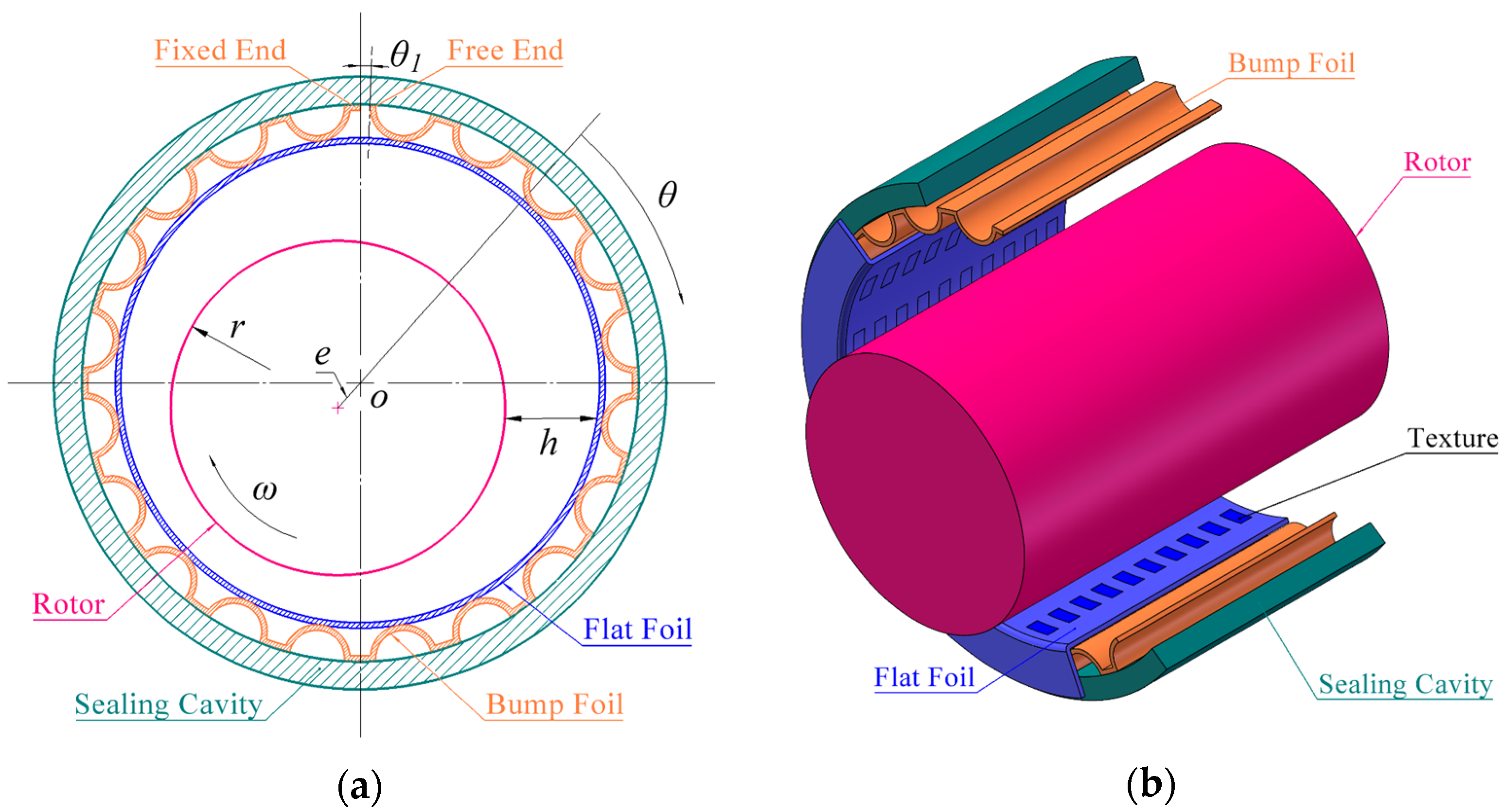
2.1. Geometrical Structure
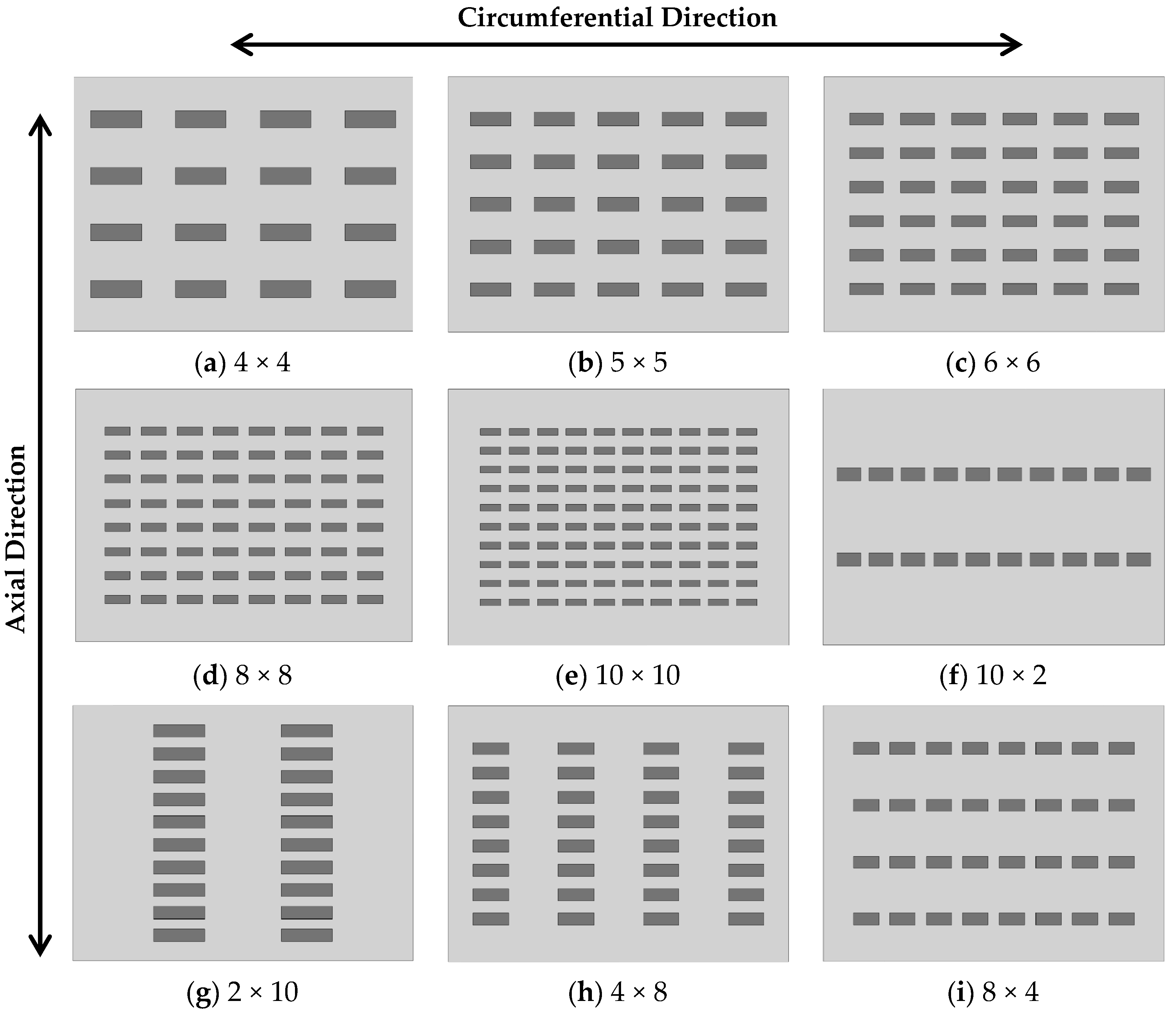
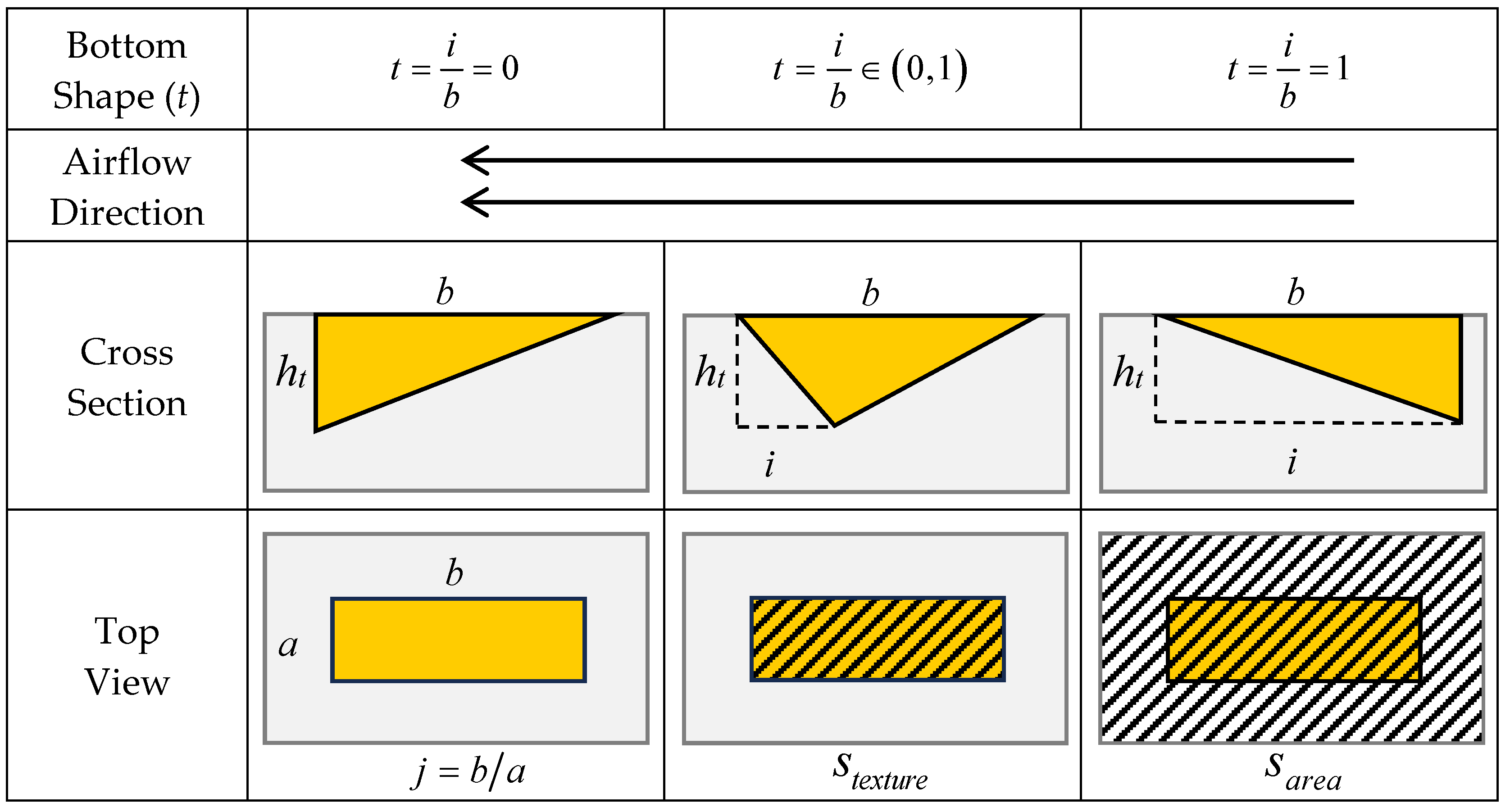
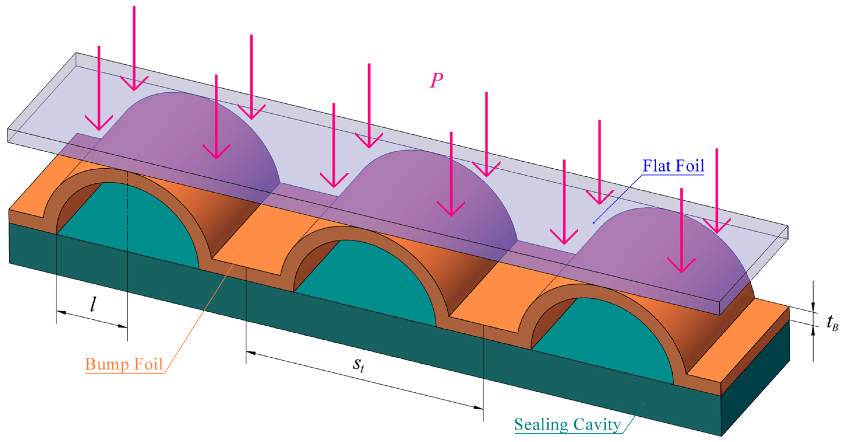
The compliant foil gas film seal is a kind of non-contact seal, as shown in Figure 1a. It consists mainly of a sealing cavity, flat foil, bump foil, and a rigid shaft [20]. The compliant foil seal is eccentrically mounted, and a wedge-shaped convergence angle is formed between the shaft and the flat foil. When the rotating shaft is running at high speed, there will be a certain pressure of air between the flat foil and the rotating shaft, so as to achieve the effect of gas film sealing. Meanwhile, the foil undergoes elastic deformation due to the air pressure difference, ensuring that the shaft and foil remain in a non-contact state, thus effectively reducing the friction and wear caused by the shaft offset and disturbance. The deformation of the foil will increase the thickness of the sealing gas film to a certain extent, so that the pressure of the sealing gas film is reduced, affecting the sealing effect. As shown in Figure 1b, the texture configuration is designed on the flat foil. Numerous practical experiences demonstrate that texture can enhance the dynamic pressure in high-speed rotating systems [13,14,18,19,20], thereby increasing the gas film pressure.
The fluid is assumed to be Newtonian and compressible, ignoring temperature, inertia, and squeeze film effect. For a compliant foil gas film seal operating in steady state, the Reynolds equation used to solve the gas film flow field is given by Equations (1) and (2):
1 R 2 θ h 3 p 2 θ + z h 3 p 2 z = 12 μ ω θ ( p h )
1 R 2 θ p h 3 p θ + z p h 3 p z = 6 μ U R θ ( p h )
where R is the radius of the shaft, h is the thickness distribution of the sealing gas film, p is the pressure distribution of the sealing gas film, μ is the viscosity of the sealing gas, and ω is the angular velocity of the shaft.
According to the geometric structure of the compliant foil seal, the position of the shaft eccentricity, the parameters of the foil deformation, and the design parameters of the texture, the thickness equation of the sealing gas film can be obtained as shown in Equation (3):
h = c + e cos θ + h 1 + h 2
where c is the average thickness of the initial sealing gas film, e is the eccentricity of the shaft, θ is the circumferential coordinate, h 1 and h 2 are the texture depth distribution and the foil deformation distribution, respectively.

2.2. Texture Design

The texture is opened on the surface of the flat foil. This study first examines the impact of texture configuration on the sealing performance of the compliant foil. The designed configuration is shown in Figure 2.
The design scheme of the bottom shape of the texture is shown in Figure 3. The bottom shape of the texture includes 2 inverted right-angle bottom surfaces and 9 V-shaped bottom surfaces with different inclination degrees, a total of 11 bottom shapes. In Figure 3, b is the length of the rectangular edge along the circumferential direction of the texture surface, ht is the depth of the deepest texture, i is the length of the position of the deepest texture perpendicular to the texture surface from the left edge of the texture, t = i / b and 0 ≤ t ≤ 1.
Figure 3 shows the top view of the unfolded flat foil surface, where a is the length of the rectangle of the textured surface along the axial direction, s a r e a is the area of the whole area divided equally according to the configuration, s t e x t u r e is the area of the texture in the area; they are represented by the shadow part in Figure 3, respectively. The aspect ratio is defined as j = b / a , and the area ratio of the texture is defined as s = s t e x t u r e / s a r e a .

2.3. Foil Deformation Model

Figure 4 shows the foil deformation structure diagram, and the wave foil is modeled as a linear elastic spring with stiffness k b . Neglecting the deformation of the flat foil and the Coulomb friction between the flat and bump foils [24], the foil deformation equation is as follows:
P P a = k b s t h 2
where P is the pressure distribution of the sealing gas film, P a is the atmospheric pressure outside the foil, k b is the unit stiffness distribution of the foil, and s t is the length of a single wave foil. The calculation equation of k b is as follows [24]:
k b = E b t B 3 2 l 3 1 v b 2
where E b represents the elastic modulus of the foil material, v b is the Poisson coefficient of the foil material, l is half of the length of the bump foil chord, and t B is the thickness of the bump foil.
The geometric structure and mechanical properties of the compliant foil gas seal used in the calculation in this paper are listed in Table 1.

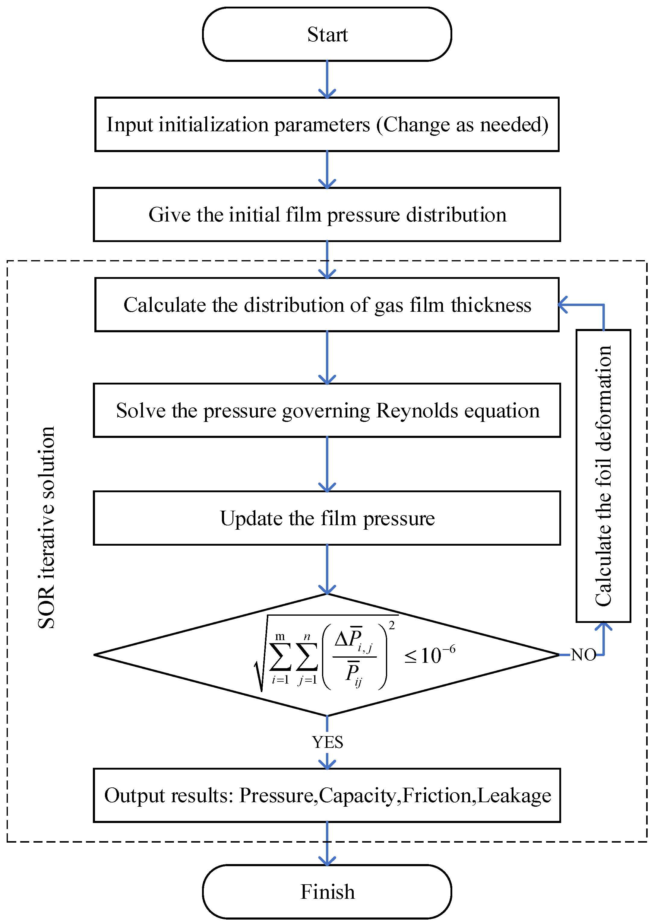
2.4. Solution Method

In this study, the central difference method is used to difference the dimensionless Reynolds equation, and the pointwise iterative method is used to complete the iterative calculation of the difference equation by MATLAB R2022b programming. The dimensionless equation of Equation (1) is obtained as follows:
R 2 L 2 3 H H z ¯ p ¯ z ¯ + R 2 L 2 2 p ¯ z ¯ 2 + 3 H H θ p ¯ θ + 2 p ¯ θ 2 = 2 Λ p a p H 3 H 2 p ¯ θ + p ¯ H θ
where Λ = 6 μ ω p a R c 2 , the dimensionless parameter is defined as:
z ¯ = z L , p ¯ = p 2 p a 2 , H = h c
The complaint foil gas film is expanded and meshed. The mesh division diagram is shown in Figure 5:
The following central difference scheme is introduced:
2 p ¯ z ¯ 2 = p ¯ i , j + 1 2 p ¯ i , j + p ¯ i , j 1 Δ z ¯ 2   2 p ¯ θ 2 = p ¯ i + 1 , j 2 p ¯ i , j + p ¯ i 1 , j Δ θ 2   p ¯ z ¯ = p ¯ i , j + 1 p ¯ i , j 1 2 Δ z ¯
p ¯ θ = p ¯ i + 1 , j p ¯ i 1 , j 2 Δ θ   H z ¯ = H i , j + 1 H i , j 1 2 Δ z ¯   H θ = H i + 1 , j H i 1 , j 2 Δ θ
The central difference Reynolds equation is obtained as follows:
A i , j p ¯ i 1 , j + B i , j p ¯ i + 1 , j + C i , j p ¯ i , j + D i , j p ¯ i 1 , j + E i , j p ¯ i , j + 1 = F i , j
where A i , j , B i , j , C i , j , D i , j , E i , j are the known coefficients in the derivation process. For the dimensionless parameter p ¯ , its n+1th. value can be obtained by iterating the nth. value. The equation is as follows:
p ¯ i , j n + 1 = ( A i , j p ¯ i 1 , j n + 1 + B i , j p ¯ i + 1 , j n + D i , j p ¯ i , j 1 n + 1 + E i , j p ¯ i , j + 1 n + F i , j ) / C i , j
When the following convergence conditions are satisfied, the iteration stops and the solution is completed:
i = 1 m j = 1 n Δ p ¯ i , j p ¯ i , j 2 10 6
The boundary conditions are as follows:
p z = 0 , θ = p h i g h p z = L , θ = p l o w p z , θ = 0 = p z , θ = 2 π
where p l o w is the pressure at the low-pressure end of the compliant foil seal, and p h i g h is the pressure at the high-pressure end of the compliant foil seal. The overall solution of this study is shown in Figure 6.

2.5. Performance Parameter

Traditional gas film seals often take into account the gas film buoyancy or gas film bearing capacity as an important gas film sealing parameter. For fixed eccentric rotating devices, the gas film pressure increases with the increase in gas film bearing capacity. For the compliant foil gas film seal, when the gas film pressure is higher, a larger foil deformation will be generated, so that the actual eccentricity will be reduced, which often leads to an increase in gas film pressure and a reduction in gas film bearing capacity. Therefore, in this study, the average gas film pressure is used as an important parameter to judge the dynamic pressure of texture rather than the gas film bearing capacity. At the same time, the trend of gas film bearing capacity is also listed in this study. Higher gas film pressure also indicates stronger sealing performance of the gas film. The equation of the average gas film pressure is as follows:
P ¯ = 1 m n i = 1 m j = 1 n p ¯ i , j
The bearing capacity of the sealing gas film is the integral of the gas film pressure acting on the flat foil surface. The equation is as follows:
ω ¯ = ω ¯ x 2 + ω ¯ y 2
where ω ¯ x and ω ¯ y are the sum of the pressure of the gas film on the surface of the compliant foil in the transverse and longitudinal directions, respectively. The calculation equation is as follows:
ω ¯ x = 0 1 0 2 π p ¯ θ , z ¯ 1 sin θ d θ d z ¯ ω ¯ y = 0 1 0 2 π p ¯ θ , z ¯ 1 cos θ d θ d z ¯
In addition, for the compliant foil seal, the leakage of the sealing gas is an important performance parameter, which is solved by the pressure gradient of the compliant foil gas film seal. The equation is as follows:
Q = 0 2 π R ρ h 3 12 μ p z z = L d θ
The existence of texture can reduce gas friction to a certain extent. Gas friction is a key parameter in assessing the sealing and texture performance of compliant foil. The solution equation is as follows:
T x = 0 1 0 2 π Λ 6 1 h h 2 p θ sin θ d θ d z T y = 0 1 0 2 π Λ 6 1 h h 2 p θ cos θ d θ d z

3. Validation

This study compares the research results of the compliant support cylindrical gas film seal using the finite element method by Ma et al. [5]. The results of this study have also been verified by other scholars many times. and shows good accuracy. The parameters of the compliant support cylindrical gas seal studied by Ma et al. are shown in Table 2. The results of this study are compared with the results of Ma et al., as shown in Figure 7.
When the elastic foil stiffness of the compliant foil gas film seal is infinite, the compliant foil seal can be regarded as a rigid cylindrical gas film seal with fixed eccentricity. As shown in Figure 7, the dimensionless pressure distribution in the cross section of the sealed gas film in this study under rigid conditions and the pressure distribution in the cross section of the sealed gas film studied by Ma et al. [5]. The inlet pressure represented by the two curves on the lower side of Figure 7 is atmospheric pressure, and the inlet pressure represented by the two curves on the upper side of the gas film seal in Figure 7 is 0.20 MPa. It can be seen from the figure that no matter what kind of inlet pressure, the change curve of the research results in this paper is highly consistent with the change curve of the research results of Ma et al. [5]., which ensures the accuracy of the research program.

4. Result and Discussion

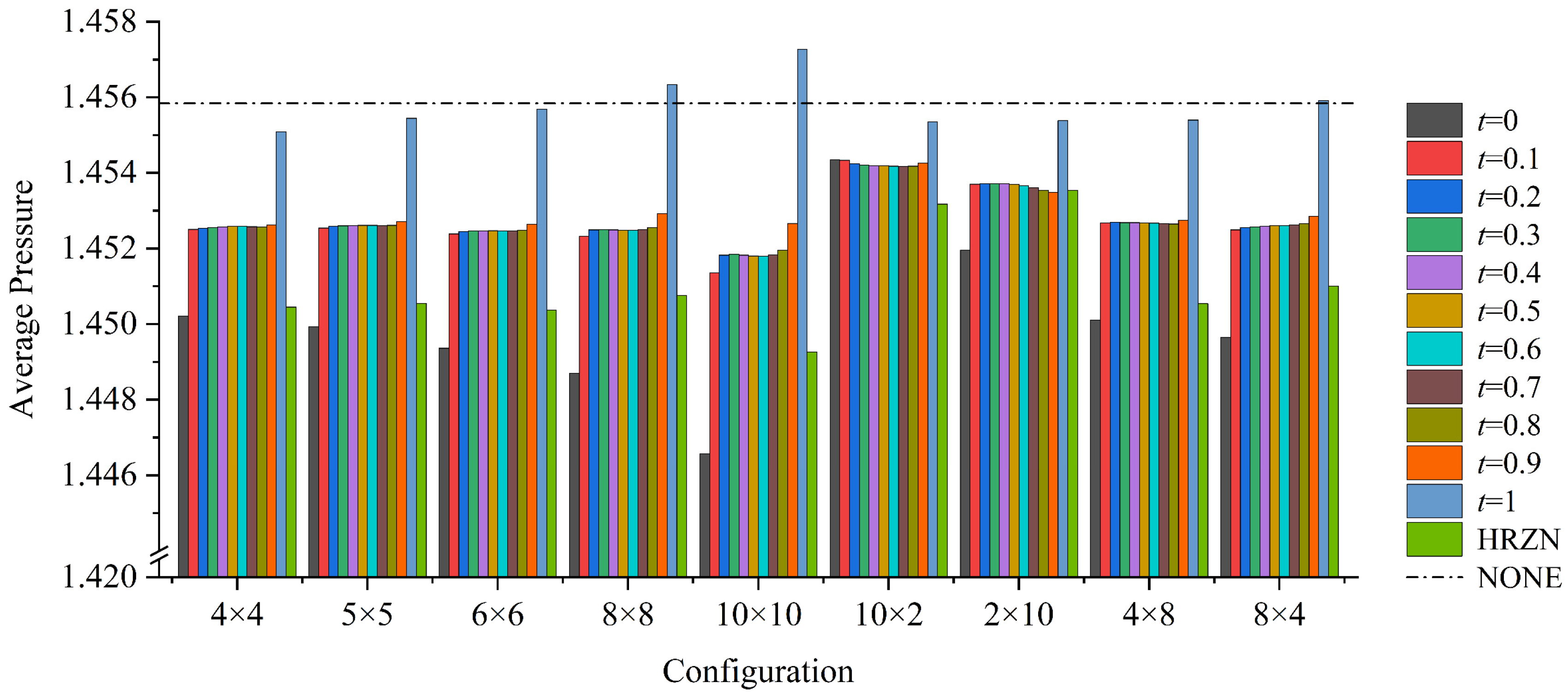
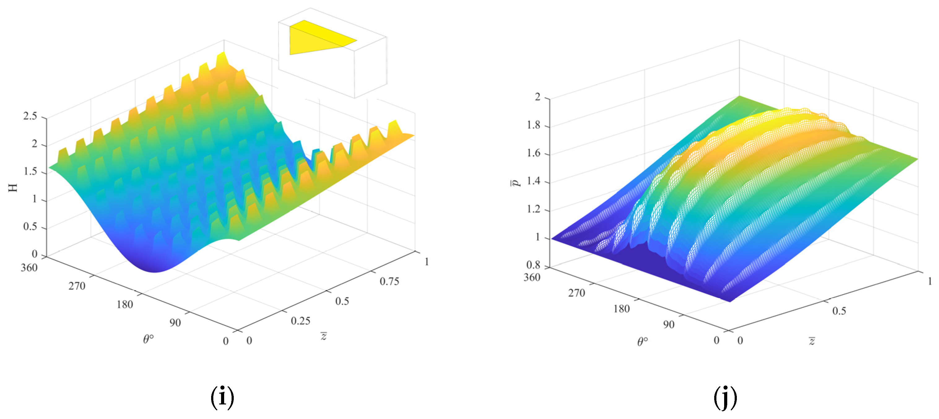
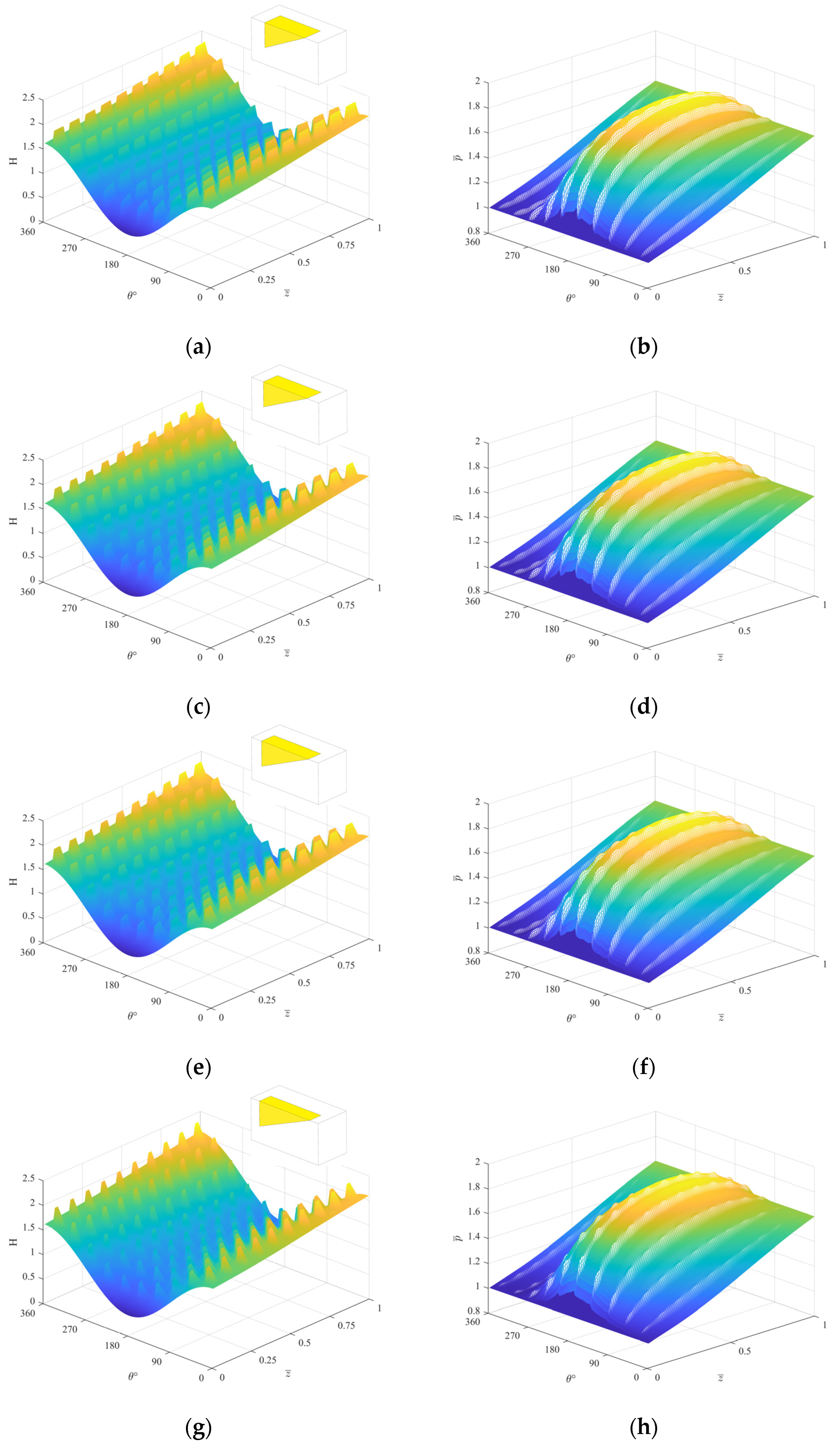
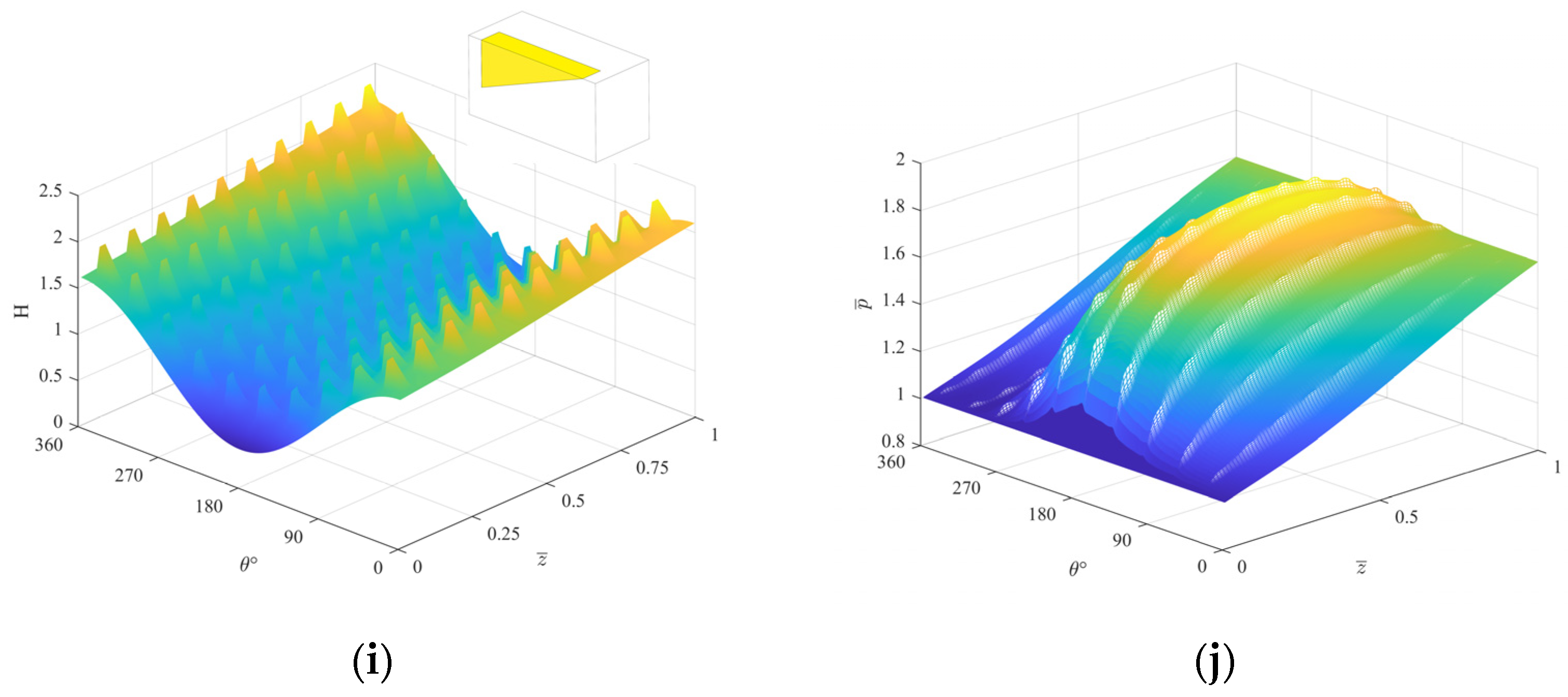
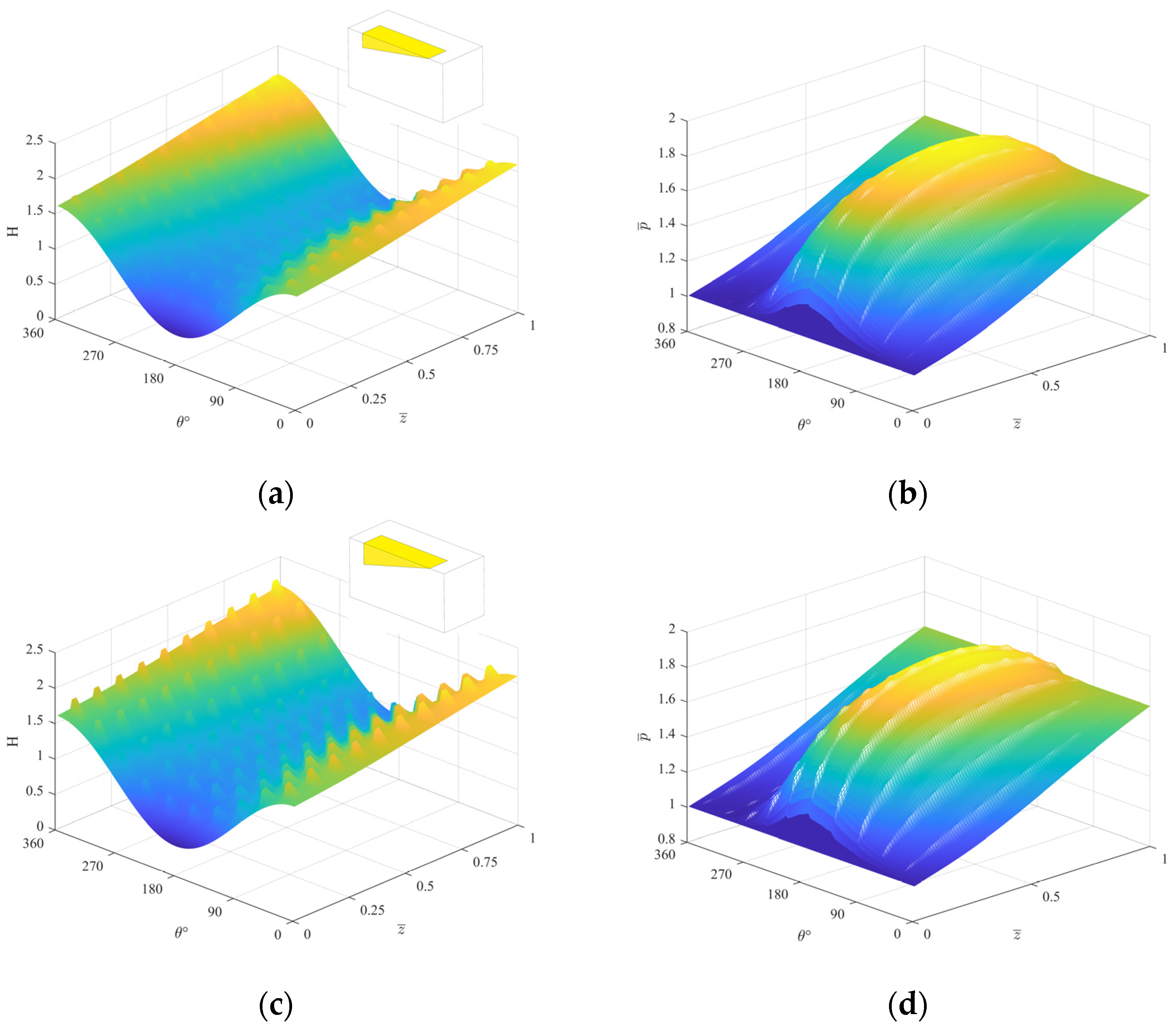
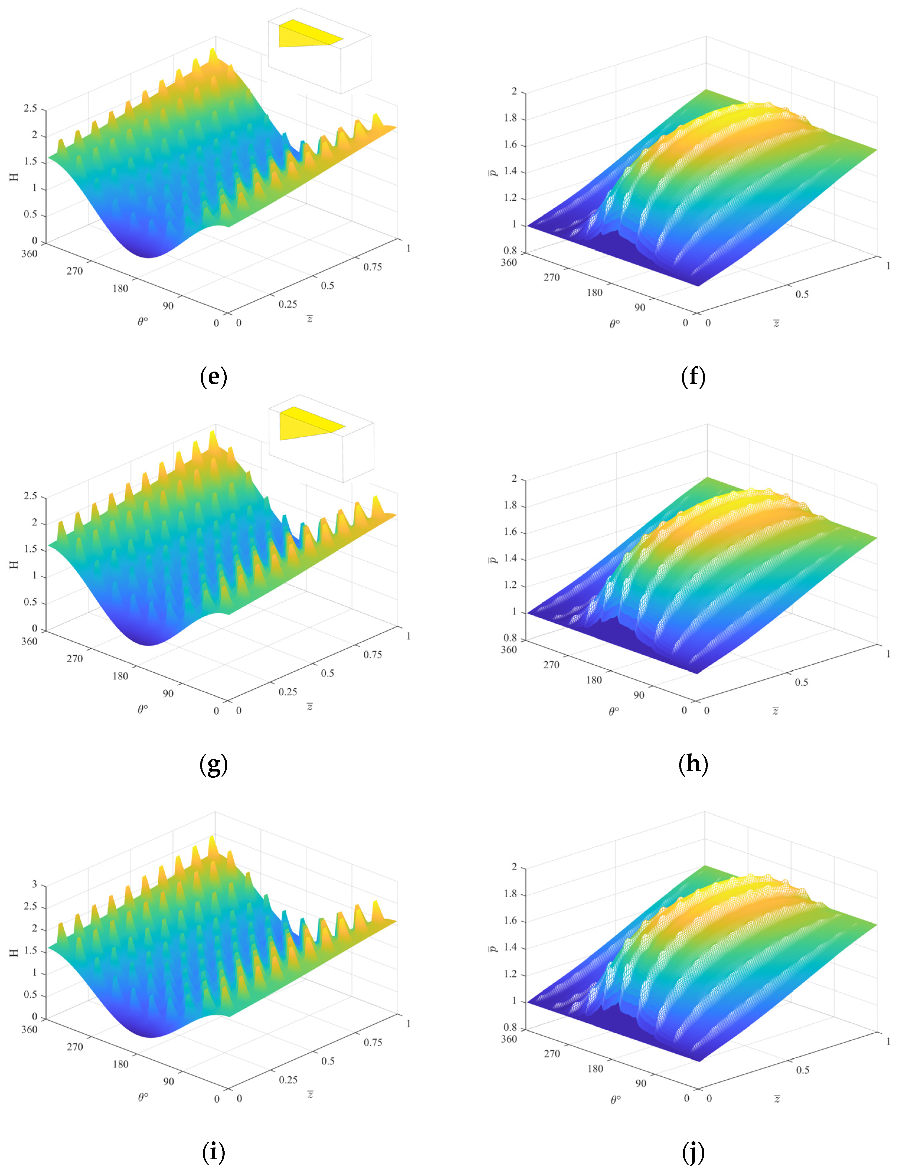
4.1. Effect of Configuration and Bottom Shape

The structural parameters and mechanical properties of Table 1 are used to set the working conditions. The aspect ratio j = 6/1 [18], the area ratio s = 0.2, and the texture depth ht = 3 μm are selected. In the case, eight kinds of rectangular textures with different configuration forms and 11 kinds of textured slope bottom shapes were selected to calculate the average gas film pressure value of the compliant foil seal, and the horizontal bottom texture (labeled as HRZN in Figure 8) and non-texture (labeled as NONE in Figure 8) were set as the reference group. The final calculation results are shown in Figure 8. Comparing the average gas film pressure of the texture under different configurations, it is found that the average gas film pressure varies with different bottom shapes, and the different configurations of the texture have no effect on the variation in the bottom shape of the texture. Under any configuration, when t = 1, that is, the texture is the bottom shape of the inverted right angle, the average gas film pressure of the compliant foil gas film seal is the largest. When t = 0, that is, the texture shape is also an inverted right angle, the average gas film pressure is the smallest. When t = 0.1, 0.2,…, 0.9, that is, the texture is V bottom, the average pressure of the compliant foil gas film seal is basically the same. The gas film pressure generated by different bottom shapes is arranged from large to small: t = 1 ≥ t = 0.1, 0.2,…, 0.9 ≥ t = 0, and the overall effect of t = 1 and t = 0.1, 0.2,…, 0.9 is better than that of the horizontal bottom. The bottom shape is improved by 0.55% when t = 1, which proves that the shape of the slope bottom is better than that of the traditional water surface bottom shape [22].
The primary reason for this phenomenon is that when t = 0, the bottom surface shape of the texture is divergent for the direction of the airflow in the flow field. When t = 0.1, 0.2,…, 0.9, the texture creates a channel that diverges first and then converges in the flow field. When the gas flows into these two types of textures, it is smoother, and the pressure gradually decreases with the wedge channel. Compared with the divergent space of t = 0.1, 0.2,…, 0.9, t = 0 is longer, and the change is more rapid when the gas flows out of the cavity, so the average gas film pressure is lower. When t = 1, the bottom shape of the texture is convergent for the airflow direction in the flow field. The gas flows into the convergent cavity, first expands and decelerates, and then, as the channel convergence leads to the decrease in the airflow channel, the gas pressure gradually recovers. In comparison to the other two bottom shapes, the texture has a longer convergence space, allowing the gas to generate a stronger secondary dynamic pressure effect as it exits the microcavity. As a result, the dynamic pressure effect is optimal when t = 1, leading to a higher average gas film pressure, which aligns with the findings of [23].
It can also be found from Figure 8 that there is a gap in the performance of the same bottom shape under different configurations. When the texture configuration gradually increases from 4 × 4 to 10 × 10, for the bottom shape of t = 0, the more the number of textures, the lower the average gas film pressure. For the bottom shape of t = 1, the average gas film pressure increases as the number of textures increases. And when the bottom shape of the texture is t = 1, the average film pressure reaches a maximum of 1.457 with the increase in the texture configuration. When the configuration is 8 × 8, 10 × 10, 8 × 4, the average gas film pressure can be higher than that without texture, which is 0.10% higher than that without texture. Therefore, the configuration of 10 × 10 is used for calculation in subsequent research.
In the case of 10 textures arranged in the circumferential and axial directions, respectively, the average gas film thickness and average gas film pressure distribution of the compliant foil gas film seal are shown in Figure 9. It can be observed from Figure 9a that due to the design of surface texture, the gas film thickness shows a local increase area at the texture. Due to the pressure difference between the inlet and outlet, the gas film thickness shows a trend of low pressure end low high pressure end high along the Z-axis direction. Comparing the average gas film thickness and the average gas film pressure in Figure 9, it is found that the pressure deformation trend under different bottom shapes is similar. It can be seen that the closer to the minimum area of gas film thickness at θ = 180º, the more significant the average gas film pressure is [20]. It can also be observed that the average gas film pressure gradually produces a higher peak value when the texture bottom shape changes from t = 0 to t = 1, which is the same as the trend in Figure 8.

4.2. Effect of Bottom Shape and Ascept Ratio

It is preliminarily found that when the texture parameter t = 1, the texture generates the strongest dynamic pressure effect. In order to further confirm that the texture shows the best dynamic pressure effect when the texture parameter t = 1, and to explore the influence of the change of the length and width of the texture on the gas film sealing performance of the compliant foil, according to the geometric structure in Figure 3, ten different aspect ratios were selected, that is, the aspect ratio j = 2/1 to j = 10/1, and the sealing performance of the compliant foil was calculated. The calculation results are shown in Figure 10.
From the Figure 10a,b,d, it can be seen that the average pressure, leakage, and friction have the same change trend when the bottom shape changes from t = 0~1 under different aspect ratios. The average pressure increases continuously with the bottom shape from t = 0 to t = 1 and presents a sharp change trend at both ends, which corresponds to Figure 8. The leakage and friction generally decrease with the change of the bottom shape from t = 0 to t = 1 and also show a sharp change trend at both ends of the middle. In the case of t = 1 texture bottom shape, the aspect ratio j = 2/1 shows the highest gas film pressure, which is 0.28% higher than the minimum gas film pressure in this case; the aspect ratio j = 2/1 shows the lowest leakage, which is 0.22% lower than the maximum leakage in this case. The aspect ratio j = 3/1 shows the lowest friction, which is 2.09% lower than the maximum friction in this case.
This is because when the bottom shape is in the case of t = 0.1, 0.2,…, 0.9, the cavity presents a trend of first divergence and then convergence. The dynamic pressure effect generated by the divergence flow channel and the convergence flow channel will cancel each other out, and the positive or negative effects generated by the single convergence and divergence cavity will be reduced compared with the single convergence and divergence cavity. Therefore, the closer the divergence of the bottom shape is to the length of the convergence section, the weaker the influence on the sealing performance. At the same time, it can be seen that when the aspect ratio is larger and the length of the texture in the circumferential direction is longer, the change trend of the curve is more gentle, and the difference between the gas film pressure, the leakage, and the friction force at t = 0 and t = 1 is smaller. This is because the increase in the circumferential length leads to the slow change trend of the convergence or divergence channel in the texture. The longer the length of the circumferential contact with the fluid, increases the viscous dissipation in the wedge space [18], and the smaller the dynamic pressure effect on the fluid. Therefore, when the aspect ratio of the texture is smaller, that is, the length of the texture in the circumferential direction is smaller, the dynamic pressure effect is better. Therefore, the strongest dynamic pressure effect can be produced when the aspect ratio is 2/1, because the cavity can produce a more dramatic change space, resulting in higher gas film pressure and lower leakage.
For Figure 10c, although the change of bearing capacity in the figure also shows a gentle trend in the middle section, there is only a slight change at both ends. This is because the compliant deformation of the foil increases the thickness of the gas film, making the real eccentric position of the shaft more centered, and the pressure difference between the upper and lower parts of the shaft becomes smaller, so that the bearing capacity changes little and shows a decreasing trend. Therefore, there is no significant difference in the bearing capacity generated by different bottom shapes, and when the aspect ratio is 8/1, the dynamic pressure effect is weaker, the bearing capacity is the highest, and its average bearing capacity under different bottom shapes is 1.18% higher than that of the aspect ratio of 7/1.
When the bottom shape parameter t = 1, the average gas film thickness and average gas film pressure distribution of the compliant foil gas film seal under different specific aspect ratios are shown in Figure 11. Similar to Figure 9a in the previous section, it is found that the pressure deformation trend under different aspect ratios is also similar. When the gas film pressure gradually produces a higher peak value when the aspect ratio of the texture changes from j = 10/1 to j = 2/1, the change trend is the same as the different gas film pressure generated by different aspect ratios when t = 1 in Figure 10a.

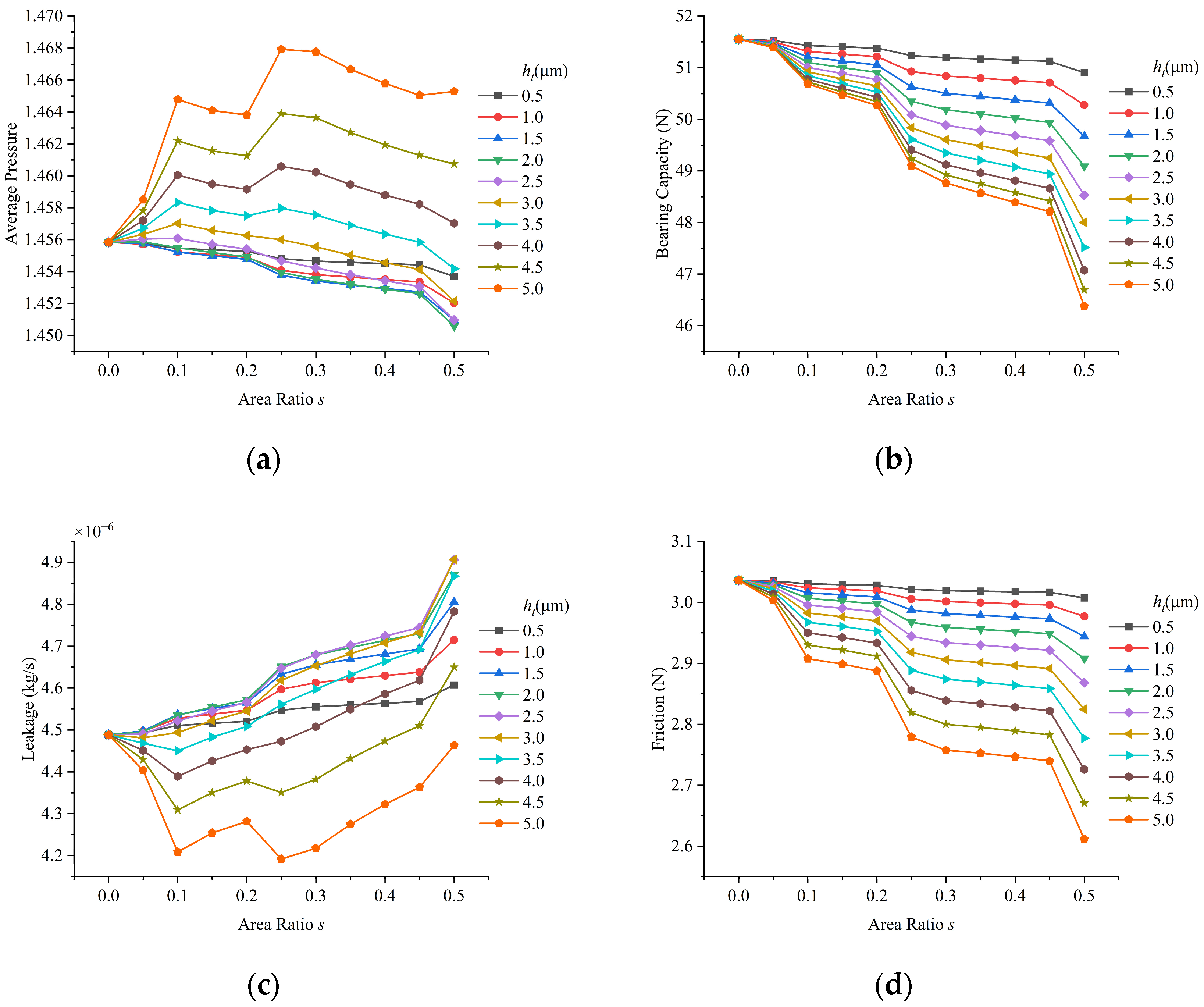
4.3. Effect of Area Ratio and Depth

In order to further explore the influence of different size changes of t = 1 texture on the sealing performance of compliant foil gas film, according to the geometric structure shown in Figure 3, 10 textures with different depths were designed, that is, the texture depth ht = 0.5~5.0 μm, and the influence of its area ratio on the sealing performance of cmpliant foil was studied. The calculation results are shown in Figure 12.
It can be seen from Figure 12b, d that the change trend of bearing capacity and friction force at different depths when the area ratio of texture s = 0~0.5 is gradually decreasing, and the greater the depth is, the greater the decrease is. When ht = 5.0 μm, compared with the case without texture, the bearing capacity decreases by about 10.04%, and the friction force decreases by about 13.99%. Moreover, in the case of any area ratio, the greater the texture depth, the lower the bearing capacity and friction, which is consistent with the results of [20]. At the same time, it can also be seen that the sealing performance of the compliant foil with texture shows lower bearing capacity and friction than that without texture.
As shown in Figure 12a,b that when the texture depth ht ≤ 5.0 μm, the average pressure decreases with the increase in the proportion of texture area, and the leakage increases with the increase in the proportion of texture area. When ht ≥ 5.0 μm, the average pressure typically increases and then decreases as the texture area proportion rises, while leakage initially decreases and then increases with the growing texture area proportion. At the same time, it can be seen that when the area ratio s is between 0.1 and 0.25, the average pressure and leakage will change, and the highest average pressure and the lowest leakage will be obtained when s = 0.25. Compared with the case without texture, it can increase the average pressure by about 0.83% and reduce the leakage by about 6.61%.
This is because when the proportion of depth and area increases, changes in both within a certain range can bring more rapid aspect convergence space to strengthen the dynamic pressure effect. Nevertheless, as the texture depth and area ratio continue to increase, the complexity of the flow field increases, and the lubricating gas film will produce vortices at the bottom after entering the texture, and the generation of vortices at the bottom will offset the energy of the upper gas film [20], weakening the dynamic pressure effect of the texture, so that the gas film pressure generated by the rectangular texture does not rise and fall, and the leakage generated does not fall and rise, which is consistent with [18].
When the texture area ratio s = 0.2, the average gas film thickness and average gas film pressure distribution of the compliant foil gas film seal under different texture depths are shown in Figure 13. Similar to Figure 11a in the previous section, it is found that the pressure deformation trends under different texture depths are also similar. When the gas film pressure changes from ht = 1.0 μm to ht = 5.0 μm, it gradually produces a higher peak value. The change trend is consistent with the different gas film pressures generated by the texture depth when s = 0.2 in Figure 12a.

5. Conclusions

In summary, this paper uses the finite difference method to iteratively solve the Reynolds equation of the sealing fluid and analyzes the influence of the bottom shape of the rectangular texture slope on the sealing performance of the compliant foil gas film. The gas film sealing performance of foils with various bottom shapes, configurations, aspect ratios, depths, and area ratios is systematically introduced and discussed. The following conclusions are obtained:
(1)
The influence of the change of the bottom shape on the performance of the compliant foil gas film seal is not affected by the configuration of the texture. The dynamic pressure effect of the texture of the convergent right-angle triangular slope (i.e., t = 1) is the best, and when the texture is arranged in the axial and circumferential directions, the average pressure of the compliant foil gas film seal can be increased by 0.55% compared with the horizontal bottom surface morphology. On the contrary, the dynamic pressure effect of the texture on the bottom surface of the diffuse right-angle triangular slope (i.e., t = 0) is the weakest. Under a certain configuration, the sealing performance of the textured compliant foil with a convergent right-angle triangular bevel bottom shape is better than that without texture, and the sealing performance of the textured compliant foil is the best when the texture is arranged in 10 axial and circumferential directions, respectively, which can be improved by 0.10% compared with the average gas film pressure without texture.
(2)
The aspect ratio of the texture shows an important influence on the performance of the compliant foil gas film seal. Under the same conditions, when the aspect ratio is smaller within a certain range, the average pressure of the compliant foil gas film seal is higher. In this study, when the aspect ratio of the texture is 2/1, the sealing gas film achieves the maximum gas film pressure and the lowest leakage. It can be found that when the length of the texture in the axial direction of the compliant foil is longer, the dynamic pressure effect is the best.
(3)
In the case of different depths, the bearing capacity and friction force generated by the bottom shape of the convergent right-angle triangular slope decrease with the increase in the texture area ratio, and the compliant foil gas film seal shows the minimum bearing capacity and friction force when the texture is 5.0 μm depth and s = 0.5 area ratio. Compared with the bearing capacity and friction force without texture, it can be reduced by 10.04% and 13.99%. In the range of texture depth ht ≤ 2.5 μm, the average gas film pressure and leakage show a monotonically decreasing and monotonically increasing trend with the increase in texture area ratio. When the depth ht = 5.0 μm, the compliant foil gas film seal with the area ratio of s = 0.25 shows the largest gas film pressure and the lowest leakage. The average pressure can be increased by 0.83% compared with the case without texture, and the leakage can be reduced by 6.61% compared with the case without texture.

Author Contributions

Conceptualization, Z.H., Y.Z. and J.S.; Methodology, Z.H., Y.Z., Z.L. and Y.G.; Validation, Y.Z.; Data curation, Y.Z.; Writing—original draft, Y.Z.; Writing—review and editing, Z.H., Y.Z., J.S., Z.L., N.L. and Y.G.; Visualization, Y.Z.; Supervision, Z.H., J.S. and N.L.; Funding acquisition, Z.H. All authors have read and agreed to the published version of the manuscript.

Funding

This research was funded by XX national science and technology major project, the Tianjin Municipal Science and Technology Bureau Science and Technology Plan Project grant number 23JCYBJC00110, the Fundamental Research Funds for the Central Universities grant number 3122023045, and the Chongqing Natural Science Foundation Project grant number CSTB2024NSCQ-MSX0388.

Data Availability Statement

The original contributions presented in the study are included in the article; further inquiries can be directed to the corresponding author.

Acknowledgments

The authors sincerely acknowledge the financial support mentioned above, which made it possible to continue this study.

Conflicts of Interest

Author Jiaxin Si and author Ning Li are employed by the company AECC Hunan Aviation Powerplant Research Institute. The remaining authors declare that the research was conducted in the absence of any commercial or financial relationships that could be construed as a potential conflicts of interest.

References

  1. Salehi, M.; Heshmat, H. Performance of a complaint foil seal in a small gas turbine engine simulator employing a hybrid foil/ball bearing support system. Tribol. Trans. 2001, 44, 458–464. [Google Scholar] [CrossRef]
  2. Salehi, M.; Heshmat, H. Non-contacting compliant foil seal for gas turbine engine. In Proceedings of the 2001 NASA Seal/Secondary Air System Workshop, Cleveland, OH, USA, 30–31 October 2001. [Google Scholar]
  3. Heshmat, H.; Walton, J. Innovative High-temperature Compliant Surface Foil Face Seal Development. In Proceedings of the AIAA/ASME/SAE/ASEE Joint Propulsion Conference, Hartford, CT, USA, 21–23 July 2008; pp. 1–13. [Google Scholar]
  4. Xu, H.J.; Liu, Z.S.; Zhang, G.H.; Wang, Y.L. Characteristics of Film Pressure Distribution of Bump Foil Gas Bearings. Bearings 2008, 6, 23–27. [Google Scholar]
  5. Ma, G.; Ping, X.; Shen, X.; Hu, G. Analysis of quasi-dynamic characteristics of compliant floating ring gas cylinder seal. Aerosp. Power 2010, 25, 1190–1196. [Google Scholar]
  6. Lee, D.H.; Kim, Y.C.; Kim, K.W. The effect of coulomb friction on the static performance of foil journal bearings. Tribol. Int. 2010, 43, 1065–1072. [Google Scholar] [CrossRef]
  7. Sun, J.; Liu, M.; Xu, Z.; Liao, T.; Hu, X.; Li, Y.; Wang, J. Coupled fluid–solid numerical simulation for flow field characteristics and supporting performance of flexible support cylindrical gas film seal. Aerospace 2021, 8, 97. [Google Scholar] [CrossRef]
  8. Jiang, H.; Yu, S.; Ding, X. Parametric Analysis of Compliant End Face Gas Film Seals Considering Slip Flow Effects. Appl. Sci. 2024, 14, 6953. [Google Scholar] [CrossRef]
  9. Wang, X.; Liu, M.; Kao-Walter, S.; Hu, X. Numerical Evaluation of Rotordynamic Coefficients for Compliant Foil Gas Seal. Appl. Sci. 2020, 10, 3828. [Google Scholar] [CrossRef]
  10. Wang, X.; Liu, M. The Seal Performance of Compliant Foil Gas Seal Based on Multi-Scale Analysis. Processes 2022, 10, 1123. [Google Scholar] [CrossRef]
  11. Hamilton, D.B.; Walowit, J.A.; Allen, C.M. A theory of lubrication by micro irregularitiesm. J. Basic Eng. 1966, 88, 177–185. [Google Scholar] [CrossRef]
  12. Luz, F.K.C.; Profito, F.J.; dos Santos, M.B.; Silva, S.A.; Costa, H.L. Deterministic Simulation of Surface Textures for the Piston Ring/Cylinder Liner System in a Free Piston Linear Engine. Lubricants 2024, 12, 12. [Google Scholar] [CrossRef]
  13. Shi, L.; Zhang, Y.; Chen, S.; Zhu, W. Comparative research on gas seal performance textured with microgrooves and microdimples. J. Braz. Soc. Mech. Sci. Eng. 2019, 41, 280. [Google Scholar] [CrossRef]
  14. Shi, L.; Wang, X.; Su, X.; Huang, W.; Wang, X. Comparison of the load-carrying performance of mechanical gas seals textured with microgrooves and microdimples. J. Tribol. 2016, 138, 021701. [Google Scholar] [CrossRef]
  15. Lu, P.; Wood, R.J.K.; Gee, M.G.; Wang, L.; Pfleging, W. The Friction Reducing Effect of Square-Shaped Surface Textures under Lubricated Line-Contacts—An Experimental Study. Lubricants 2016, 4, 26. [Google Scholar] [CrossRef]
  16. Pei, S.; Xu, H.; Yun, M.; Shi, F.; Hong, J. Effects of surface texture on the lubrication performance of the floating ring bearing. Tribol. Int. 2016, 102, 143–153. [Google Scholar] [CrossRef]
  17. Zhang, G.; Xu, K.; Han, J.; Huang, Y.; Gong, W.; Guo, Y.; Huang, Z.; Luo, X.; Liang, B. Performance of textured oil journal bearings considering the influence of related texture depth. Process. Inst. Mech. Eng. Part J J. Eng. Tribol. 2022, 236, 2105–2117. [Google Scholar] [CrossRef]
  18. Wang, S.; Ding, X.; Li, N.; Ding, J.; Zhang, L. Orientation effect on sealing characteristics of rectangular micro-textured floating ring gas film seal. Beijing Univ. Aeronaut. Astronaut. 2023, 1–18. [Google Scholar]
  19. Xu, J.; Yi, S.R.; Yang, X.C.; Ding, X.X.; Jiang, H.T. Impact Analysis of Surface Morphology on Floating Foil Film Sealing Performance. Tribology 2023, 43, 1341–1352. [Google Scholar]
  20. Xu, J. Analysis and Experimental Research on Dynamic Pressure Lubrication Characteristics of Compliant Foil Gas Film Seal. Ph.D. Thesis, Lanzhou University of Technology, Lanzhou, China, 2022. [Google Scholar]
  21. Vishal, M.; Skylab, P.B. Comparative Study on Tribological Vehavior of Foil Journal Bearings with Micro Pocket. Surf. Topogr. Metrol. Prop. 2024, 12, 015020. [Google Scholar]
  22. Lu, P.; Wood, R.J.K.; Gee, M.G.; Wang, L.; Pfleging, W. A Novel Surface Texture Shape for Directional Friction Control. Tribol. Lett. 2018, 66, 51. [Google Scholar] [CrossRef]
  23. Nanbu, T.; Ren, N.; Yasuda, Y.; Zhu, D.; Wang, J. Micro-Textures in Concentrated Conformal-Contact Lubrication: Effects of Texture Bottom Shape and Surface Relative Motion. Tribol. Lett. 2008, 29, 241–252. [Google Scholar] [CrossRef]
  24. Yan, J. Research on Dynamic Characteristics of Compliant Foil Gas Thrust Bearing-Rotor System. Master’s Thesis, Harbin Institute of Technology, Harbin, China, 2012. [Google Scholar]
Figure 1. Schematic diagram of compliant foil gas film seal structure: (a) Cross-section structure; (b) Three-dimensional structure.
Lubricants 12 00445 g001
Figure 2. Texture schematics in different circumferential and axial configurations: (a) 4 × 4; (b) 5 × 5; (c) 6 × 6; (d) 8 × 8; (e) 10 × 10; (f) 10 × 2; (g) 2 × 10; (h) 4 × 8; (i) 8 × 4.
Lubricants 12 00445 g002
Figure 3. Schematic of the texture in different bottom shapes.
Lubricants 12 00445 g003
Figure 4. Schematic of the foil deformation structure.
Lubricants 12 00445 g004
Figure 5. Schematic of the grid in the 2D flow field.
Lubricants 12 00445 g005
Figure 6. Flowchart of the numerical method.
Lubricants 12 00445 g006
Figure 7. Dimensionless pressure of mid-section with different high pressure.
Lubricants 12 00445 g007
Figure 8. Effect of texture bottom shape on average pressure under different configuration.
Lubricants 12 00445 g008
Figure 9. Distribution diagram of average film thickness and average film pressure under different bottom shapes: (a) film thickness at t = 0; (b) film pressure at t = 0; (c) film thickness at t = 0.3; (d) film pressure at t = 0.3; (e) film thickness at t = 0.5; (f) film pressure at t = 0.5; (g) film thickness at t = 0.7; (h) film pressure at t = 0.7; (i) film thickness at t = 1; (j) film pressure at t = 1.
Lubricants 12 00445 g009aLubricants 12 00445 g009b
Figure 10. Effect of texture bottom shape changes under different aspect ratios on sealing performance: (a) effect on average pressure; (b) effect on capacity; (c) effect on leakage; (d) effect on average friction.
Lubricants 12 00445 g010
Figure 11. Distribution diagram of average film thickness and average film pressure under different aspect ratios: (a) film thickness at j = 2/1; (b) film pressure at j = 2/1; (c) film thickness at j = 4/1; (d) film pressure at j = 4/1; (e) film thickness at j = 6/1; (f) film pressure at j = 6/1; (g) film thickness at j = 8/1; (h) film pressure at j = 8/1; (i) film thickness at j = 10/1; (j) film pressure at j = 10/1.
Lubricants 12 00445 g011aLubricants 12 00445 g011b
Figure 12. Effect of texture bottom area ratio changes under different depths on sealing performance: (a) effect on average pressure; (b) effect on capacity; (c) effect on leakage; (d) effect on average friction.
Lubricants 12 00445 g012
Figure 13. Distribution diagram of average film thickness and average film pressure under different depths: (a) film thickness at h = 1; (b) film pressure at h = 1; (c) film thickness at h = 2; (d) film pressure at h = 2; (e) film thickness at h = 3; (f) film pressure at h = 3; (g) film thickness at h = 4; (h) film pressure at h = 4; (i) film thickness at h = 5; (j) film pressure at h = 5.
Lubricants 12 00445 g013aLubricants 12 00445 g013b
Table 1. Geometry and mechanical properties of compliant foil gas seal.
ParameterValueParameterValue
R [mm]25tB [mm]0.2016
L [mm]26.67μ [Pa·s]1.8 × 10⁻⁵
c [μm]10Pa [MPa]0.101325
e0.6Phigh [MPa]0.16
Eb [GPa]2.14 × 10¹¹ω [r/min]30000
vb0.3st [mm]4.572
l [mm]1.778μf0.10
Table 2. Calculation parameters of seal.
ParameterValueParameterValue
Eccentricity0.5Viscosity [10−5 Pa·s]1.932
Clearance [10−6 m]10Density [kg/m3]1.1614
Width of seal [10−3 m]40Pressure of low side [MPa]0.11
Diameter of rotor [10−3 m]160Pressure of high side [MPa]0.11, 0.20
Speed of rotor [r/min]25,000Lubricants 12 00445 i001Lubricants 12 00445 i002
Disclaimer/Publisher’s Note: The statements, opinions and data contained in all publications are solely those of the individual author(s) and contributor(s) and not of MDPI and/or the editor(s). MDPI and/or the editor(s) disclaim responsibility for any injury to people or property resulting from any ideas, methods, instructions or products referred to in the content.

