Article

Study on the Effects of CeO2 on the Micro-Structure and Wear Resistance of CuCrZr Plasma Cladding Coatings

1
National Demonstration Center of Experimental Teaching for Ammunition Support and Safety Evaluation Education, Army Engineering University of PLA, Shijiazhuang 050000, China
2
Department of Materials Engineering, Hebei Vocational University of Industry and Technology, Shijiazhuang 050000, China
3
Department of Electrical and Information Engineering, Hebei Jiaotong Vocational and Technical College, Shijiazhuang 050000, China
*
Authors to whom correspondence should be addressed.
Lubricants 2024, 12(12), 409; https://doi.org/10.3390/lubricants12120409
Submission received: 3 November 2024 / Revised: 22 November 2024 / Accepted: 22 November 2024 / Published: 24 November 2024

Abstract

:
The electromagnetic railgun, a novel kinetic energy weapon, has found utility in military operations due to its enhanced safety features and superior precision. This study investigates the enhancement of wear resistance in CuCrZr rails through the plasma cladding of CuCrZr-CeO2 coatings with a varying Cerium dioxide (CeO2) content. To enhance the wear resistance of the CuCrZr track, plasma cladding of CuCrZr-CeO2 coatings with varying CeO2 content was investigated. The impact of CeO2 content (0%, 0.1%, 0.15%, 0.2%, 0.25%, 0.3%) on the microstructure, phase composition, and mechanical properties of the CuCrZr coating was assessed using scanning electron microscopy (SEM), X-ray diffraction (XRD), EDS (Energy Dispersive Spectrometer) surface scanning, friction and wear tests, and hardness analysis. The findings indicate that a CeO2 content of 0.15% leads to a transition in the coating’s microstructure from columnar to equiaxed crystals, with the densest grain structure. Beyond 0.15% CeO2, pore defects in the coating increase, compromising mechanical properties. The coating containing 0.15% CeO2 exhibits optimal performance, with a hardness of 75.3, representing a 5.31% increase compared to CeO2-free CuCrZr coatings. Under a 10 N load, the friction coefficient decreases by approximately 17.9% to about 0.64. Moreover, the minimum wear mass is reduced by 44.7% to 3.87 mg. The aforementioned research findings hold immense importance in extending the lifespan of the electromagnetic railgun and improving its operational efficiency.

1. Introduction

The electromagnetic railgun represents a novel kinetic energy weapon concept that has garnered significant attention in modern weapon technology advancements. Known for its high rate of fire, long range capabilities, and cost-effective launch method, the electromagnetic railgun has become a focal point in military research [1,2]. The electromagnetic railgun, a novel weapon system, has demonstrated significant technological advancements in recent years. This technology harnesses electromagnetic forces to propel projectiles at high velocities and precision, surpassing the range capabilities of traditional artillery. Through advancements in materials science and electromagnetic technology, researchers have achieved breakthroughs in energy storage, emission mechanisms, and thermal regulation. The fundamental components of an electromagnetic railgun comprise a launch track, an energy storage device, and a control system. Typically, the launch track consists of paired conductive rails that create a robust electromagnetic field for accelerating the projectile [3,4]. Energy storage devices commonly utilize supercapacitors or high-energy batteries to deliver instantaneous high-power output. Currently, the CuCrZr matrix track is extensively utilized in electromagnetic railgun systems. This alloy effectively minimizes energy loss and enhances launch efficiency under high-current conditions. Moreover, the material exhibits superior mechanical strength, corrosion resistance, and suitability for demanding operational environments, rendering the CuCrZr matrix an optimal choice for electromagnetic railgun design. However, operational challenges such as transition ablation, planing, groove erosion, and the velocity skin effect arise as the armature moves swiftly along the track [5]. Lian et al. [6] used Ni45A-TiC-CeO2 as cladding material to perform laser cladding on metal surfaces, proving that the addition of CeO2 enhanced the coating quality and mechanical properties, and that CeO2 could significantly improve its wear resistance [7,8,9]. CeO2 is a crucial rare earth metal oxide known for its exceptional chemical stability and superior tribological properties. Recent research indicates that coating metal surfaces with cerium dioxide significantly enhances wear resistance due to its hardness and heat resistance, effectively combating wear [7,8,9,10]. The utilization of cerium dioxide in surface treatment of steel, aluminum alloys, and other metals has emerged as a key technique. The nanostructuring of cerium dioxide enhances its potential applications in composite materials, particularly in enhancing mechanical and wear-resistant properties when combined with polymers or other ceramics. This composite material exhibits promising applications in aerospace, automotive manufacturing, and various other industries [11,12,13].
In this study, plasma cladding is adopted for coating cladding. Plasma cladding technology has obvious advantages in improving material surface properties, reducing production costs, and improving production efficiency [14,15,16,17,18], and is more suitable for mass production of rails. Despite the limited research on utilizing CeO2 for surface modification of CuCrZr matrices in electromagnetic railgun tracks, this study pioneers the use of CeO2 as a modifying element. Various CuCrZr-CeO2 coatings with different CeO2 contents were applied to the electromagnetic railgun track surface using plasma cladding. The microstructural and property changes of these coatings were analyzed. The results demonstrated the successful production of high-performance CuCrZr-CeO2 coatings, leading to improved track lifespan and enhanced operational efficiency of the electromagnetic railgun. This advancement holds significant implications for the progress of electromagnetic railgun technology.

2. Materials and Methods

2.1. Coating Preparation

The CuCrZr track, extensively utilized in electromagnetic railguns, not only matches the electrical conductivity of pure copper tracks but also exhibits enhanced mechanical properties. The composition of the CuCrZr electromagnetic railgun track is detailed in Table 1.
CeO2 and CuCrZr powders were procured from Shijiazhuang (Hebei, China) Dongming New Material Technology Co., Ltd. The CuCrZr powder had an average particle size ranging from 400–500 nm, with the particle size distribution based on strength, quantity, and volume depicted in Figure 1a. The majority of particles fell within the 400–500 nm range, as illustrated in Figure 1a. The macro color of CuCrZr powder is dark yellow, exhibiting a microstructure of spherical particles, as depicted in Figure 1b. Table 2 outlines the composition of the powder, primarily consisting of Cu with minor amounts of Cr and Zr elements. CeO2 powder, characterized by irregular particles, displays a light-yellow hue, with its microscopic morphology presented in Figure 1c.
A 100 g GuZrCr metal alloy powder was combined with CeO2 powder in varying amounts (0.001 g, 0.0015 g, 0.002 g, 0.0025 g, 0.003 g) and mechanically mixed for 1 h to produce CuCrZr-CeO2 mixed powder compositions containing CeO2 concentrations of 0.1%, 0.15%, 0.2%, 0.25%, and 0.3%. Subsequently, CuCrZr-CeO2 coatings were applied onto a CuCrZr orbital matrix using plasma cladding equipment, with the matrix dimensions set at 20 mm × 20 mm × 20 mm. The matrix was then sanded, subjected to ultrasonic cleaning in alcohol to eliminate surface impurities, and dried thoroughly. Specific cladding parameters are detailed in Table 3. Prior to testing, the substrate track was preheated to 300 °C. During the test preparation phase, the molten pool temperature was maintained at 1700 °C. Following completion of the cladding process, the sample was insulated using insulation sand until it cooled to room temperature. The macroscopic view of the coating post-cladding is illustrated in Figure 2. When 0.3% CeO2 is incorporated, the red box highlights a distinct presence of macroscopic void defects. The overall coating appeared dense and smooth, but at a CeO2 addition of 0.3%, numerous surface porosity defects were observed.

2.2. Characterization and Testing Methods

The microstructure analysis was conducted collaboratively by Scientific Compass Testing Service Company, Hebei Material Fine Crystal Preparation Technology Center, and Hebei Iron and Steel Group Material Research Institute. The Zeiss metallographic microscope was utilized to observe the microstructure of the coating, while the scanning electron microscope (ZEISS GeminiSEM 300, Baoding, China) was employed to examine the microstructure of the powder, coating, and friction and wear marks. Elemental distribution on the coating surface was determined using an ESD spectrometer. The phase composition of the coating was assessed with an X-ray diffractometer, surface wear morphology was evaluated with a surface profilometer, and the wear rate was subsequently calculated.
The coating’s hardness was assessed using a Wilson MicroVickers hardness tester (Wilson, Tukon 2500, Shijiazhuang, China) at the Materials Research Institute of Hebei Iron and Steel Group. XRD analysis was conducted by the Hebei Fine Crystal Material Preparation Technology Center utilizing an X-ray diffractometer, scanning angles from 10° to 80° at a speed of 2°/min. Copper was the target material.
Friction and wear testing were conducted by Scientific Compass Testing Services. Prior to the friction test, the coating underwent polishing with various grades of diamond sandpaper (400#, 800#, 1500#, 2000#) to achieve a smooth surface. Subsequently, the polished coating was subjected to ultrasonic cleaning in anhydrous ethanol for 30 min to eliminate surface contaminants. The tribological assessment was performed using a reciprocating friction test apparatus, utilizing a GGr155 steel ball with a 6 mm diameter for linear reciprocating friction evaluation at ambient temperature. The testing parameters included a load of 10 N, a friction velocity of 100 mm/s, a stroke length of 8 mm, and a duration of 30 min. The friction coefficient was directly determined from the software of the testing machine.

3. Results and Discussion

3.1. XRD Phase Analysis

The X-ray diffraction (XRD) pattern in Figure 3 illustrates the coatings with varying CeO2 concentrations (0.1%, 0.15%, 0.2%, 0.25%, and 0.3%). The spectral lines of all five powders exhibit pure Cu diffraction peaks without any new phases introduced by the incorporation of CeO2 powder. This absence of new phases may be attributed to the dispersion of CeO2 as fine particles within the coating, forming a composite structure with the matrix that retains the primary characteristics of the original phase. Alternatively, it is possible that the XRD detection sensitivity is influenced by the sample content, and the low CeO2 concentrations used in this study may fall below the equipment’s detection threshold, precluding the identification of new phases. The CeO2 content employed in this investigation is minimal, likely below the detection limit of the apparatus, thus preventing the detection of any new phases [19].

3.2. Microstructure and Element Distribution of Coatings

The microstructure of the coating was initially characterized. Figure 4a presents the surface morphology of the plasma cladding coating containing 0% CeO2, predominantly exhibiting columnar crystal structures with anisotropic properties. The coating primarily consists of a copper matrix with dispersed Cr and Zr phases. Subsequent subfigures (Figure 4b–f) depict scanning electron microscope (SEM) images of the cladding coating surfaces with incremental additions of CeO2 at 0.1%, 0.15%, 0.2%, 0.25%, and 0.3%, respectively. The images reveal significant variations in grain morphology and size within the cladding layer corresponding to the varying CeO2 concentrations. At 0.1% CeO2, the grain size is reduced compared to the 0% CeO2 coating, transitioning dendrites into equiaxial crystals; however, the composition distribution is non-uniform, displaying defects like segregation. Increasing the CeO2 content to 0.15% results in more uniform and densely packed grains than at 0.2%, where all grains transform into equiaxed crystals, exhibiting the highest density. At 0.2% CeO2, fine grains persist, forming a substantial area of equiaxed crystals, yet component segregation and the onset of void defects become apparent. With a CeO2 addition of 0.25%, internal defects within the coating escalate. Finally, at 0.3% CeO2, the grain size increases, accompanied by a broader spectrum of defects. The findings demonstrate that the addition of CeO2 hinders the growth of columnar crystals, facilitates the development of equiaxed crystals, and significantly refines grain size, with optimal results observed at a 0.15% addition rate. This phenomenon is attributed to the ability of CeO2 to act as a stable dopant, creating a passivation layer at grain boundaries that lowers their energy levels. As a result, the formation of equiaxed crystals is promoted while the growth of columnar crystals is inhibited. Additionally, CeO2 enhances the nucleation process, leading to the formation of a greater number of fine grains during the initial stages, as opposed to a few larger grains. This increased nucleation rate contributes to a higher proportion of fine grains. Furthermore, CeO2 may impede the formation of unfavorable phases, such as high-temperature phases, thereby favoring the dominance of the more stable equiaxed phase.
To investigate the impact of CeO2 content on element distribution within the coating, EDS scanning was employed. Figure 5 shows the distribution of elements, and Figure 6 shows the quantitative analysis results of elements. The analysis revealed that Cu predominantly resided in the matrix, while Zr, Cr, and Ce exhibited uniform distribution. Figure 5 displays the EDS surface scan element distribution for CeO2 coatings ranging from 0.1% to 0.3%. Furthermore, SEM imaging indicated the prevalence of the Cu phase in the coating, with the presence of Ce gradually increasing with higher CeO2 content. When the CeO2 addition reached 0.3%, a decrease in the Ce element was observed in the quantitative results of EDS scanning. This reduction can be attributed to the presence of numerous coating defects at this concentration, leading to potential deviations during scanning [20].
Upon integration with XRD data, it was observed that Zr, Cr, and Ce were present in the microstructure scan, despite not being detected in the XRD pattern, possibly due to their low concentrations falling below the equipment’s detection limit. Moreover, the incorporation of CeO2 did not introduce a new phase; instead, it dispersed within the coating as fine particles, forming a synergistic composite structure with the matrix while preserving the primary characteristics of the original phase.

3.3. Mechanical Properties of Coating

The Vickers hardness line diagram in Figure 7 illustrates the impact of CeO2 content on the hardness of the coating under an HV0.1 load. The results indicate that the addition of 0.15% CeO2 yields the highest hardness value of 75.3, representing a 5.31% increase compared to the coating without CeO2. Following this, the coating with 0.2% CeO2 shows a hardness of 73.4, marking a 2.66% rise from the baseline. Similarly, the coating with 0.1% CeO2 exhibits a hardness of 72.6, reflecting a 1.26% increase, while the coating with 0.25% CeO2 records a hardness of 70.2. Conversely, the coating with 0.3% CeO2 displays a lower hardness of 65.8 compared to the CeO2-free coating. The variations in hardness are attributed to differences in phase composition and microstructure. Despite the low CeO2 content, no new phases were detected in the XRD analysis. Microscopic examination reveals that the addition of 0.15% CeO2 results in uniform and densely packed equiaxial crystals, attributed to CeO2’s role as a grain refiner. CeO2’s oxide properties facilitate the formation of finely dispersed phases in the melt, inhibiting grain growth [21]. Furthermore, CeO2’s high melting point and chemical stability ensure its efficacy in high-temperature friction conditions, thereby enhancing the mechanical properties of the coating. Incorporating an optimal quantity of CeO2 serves to enhance both the microstructure and mechanical properties of CuCrZr coatings. The study findings indicate that the mechanical properties are optimized at a 0.15% addition rate. Conversely, a 0.1% addition rate results in an unstable microstructure due to insufficient CeO2 for uniform strengthening phase formation. Exceeding a 0.15% addition rate adversely impacts the matrix microstructure and weakens interface binding force. Moreover, excessive CeO2 can lead to coarse grain enlargement, increased coating brittleness, and reduced macro-level hardness.

3.4. Coating Friction and Wear

The friction coefficient of the CuCrZr coating, subjected to a 10 N load, exhibits time-dependent variation, as depicted in Figure 8. Notably, at a CeO2 content of 0.1%, the friction coefficient displays erratic behavior, likely attributed to the dispersion of CeO2 particles and their interactions within the matrix. Despite these fluctuations, the overall friction coefficient of the CeO2-containing coating remains lower than that of the CeO2-free counterpart, primarily due to the lubricating properties of CeO2 and its enhancement of the friction surface microstructure. Specifically, the coating with 0.15% CeO2 exhibited the most stable coefficient of friction at approximately 0.64, while the coating lacking CeO2 had a coefficient of friction of around 0.78, resulting in a 17.9% decrease in friction coefficient. This stability is attributed to CeO2’s ability to optimize the coating microstructure at this concentration, thereby enhancing solid solution strengthening of the substrate and improving the coating’s lubricating characteristics. When the CeO2 content is at 0.2%, the friction coefficient of the coating stabilizes at approximately 0.76, slightly below the value of the coating lacking this additive by about 2.5%. Upon increasing the CeO2 addition to 0.25%, the friction coefficient starts to exhibit instability, characterized by significant fluctuations over time due to the formation of holes and bubble defects in the coating. This instability intensifies at a CeO2 addition of 0.3%, leading to pronounced fluctuations in the friction coefficient as a result of numerous holes within the coating and poor adhesion to the substrate, rendering the friction curve less indicative. Beyond an addition of 0.15%, the friction coefficient once again becomes unstable and rises. This instability is attributed to the alteration of the coating’s microstructure and the development of uneven CeO2 distribution, disrupting the contact between friction surfaces and consequently increasing friction resistance. Moreover, excessive CeO2 may compromise the lubrication properties of the coating, causing varying friction coefficients under different operational conditions and diminishing the overall performance and reliability of the material.
The coating surface’s trace profile post-friction and wear testing was analyzed using a profilometer. Figure 9 illustrates the topographical contour of the wear mark’s central section under a 10 N friction load, with a 3 mm length selected for assessment. The wear volume varied with different CeO2 additions: 0% CeO2 resulted in a wear volume of 0.6732 mm3. Introducing 0.1% CeO2 decreased the wear volume to 0.3798 mm3, narrowing the wear trace width compared to the uncoated surface, displaying uneven depths at the bottom. At 0.15% CeO2 inclusion, the wear volume decreased to 0.0879 mm3, showing narrower wear marks, varied bottom depths, and pronounced protrusions of a hard phase. A 0.2% CeO2 addition resulted in a wear volume of 0.0980 mm3, widening wear marks, uneven bottoms, and reduced bulges. With 0.25% CeO2, the wear volume increased to 0.9543 mm3, showing amplified wear and deeper bottom depressions. At 0.3% CeO2 content, the wear volume peaked at 0.9851 mm3. Notably, the 0.15% CeO2 addition facilitated grain refinement in the coating, enhancing material strength and toughness through a fine crystal structure [22], thereby boosting wear resistance and reducing wear volume.
When subjected to a 10 N load, the wear mass, as depicted in Figure 10, exhibits a pattern of initial decrease, followed by an increase with the progressive addition of CeO2. At a CeO2 content of 0.15%, the coating demonstrates the lowest wear mass at 3.87 mg, representing a reduction of 3.13 mg compared to the additive-free coating, equivalent to a 44.7% decrease. Conversely, when the CeO2 content exceeds 0.2%, the coating quality diminishes, manifesting numerous holes and wear masses of 7.89 mg and 9.03 mg, respectively, surpassing those of the unalloyed coating. This behavior is primarily ascribed to the strength of CeO2 particles and their enhanced lubricating properties. The incorporation of CeO2 particles as a dispersed phase within the alloy matrix not only bolsters matrix hardness and wear resistance but also ameliorates frictional characteristics at the contact interface. Furthermore, CeO2 facilitates the formation of a compact oxide film during wear, diminishing direct metal-to-metal contact, lowering the friction coefficient, and effectively mitigating wear.
The microscopic morphology of wear marks post-friction testing was observed, as depicted in Figure 11. The analysis revealed plastic deformation in the coating during dry friction and wear, attributed to the copper matrix’s low hardness and high plasticity, facilitating plastic deformation under frictional stress. Localized melting and adhesion occurred at the interface of adjacent materials, leading to irregular surface protrusions indicative of adhesive wear. Besides adhesive wear, distinct wear marks and grooves were evident, demonstrating material delamination and abrasive wear from wear particles. Microscopic examination post-testing identified numerous particles adhered to the sample surface within the wear marks, acting as wear particles that exacerbated the formation of wear mark gullies. The collective micro-morphological analysis indicates a wear mechanism characterized by a combination of adhesive and abrasive wear in the coating [23].

4. Conclusions

This study investigates the use of plasma cladding technology for preparing CuCrZr-CeO2 coating on a CuCrZr rail. The incorporation of CeO2 in the coating serves to mitigate high-speed planing induced by localized stress and enhance its wear resistance. Moreover, varying proportions of CeO2 contribute to reducing the friction coefficient, enhancing hardness, and improving the performance of the electromagnetic railgun track. The specific findings are outlined below:
(1)
The microstructure of CuCrZr-CeO2 coating transitions from columnar to equiaxial with increasing CeO2 content, leading to gradual homogenization. This transformation occurs due to the ability of CeO2 particles to nucleate at grain boundaries in CuCrZr, reinforcing their strength and inhibiting grain growth.
(2)
With increasing CeO2 content, the hardness of CuCrZr-CeO2 coating initially increased and then decreased. The optimal hardness of CuCrZr-CeO2 coating reached 75.3 when the CeO2 content was 0.15%, representing a 5.31% increase. CeO2 is a ceramic material known for its high hardness and excellent wear resistance, attributed to its stable lattice structure. The addition of CeO2 effectively enhances the overall hardness of the CuCrZr matrix by forming a strong bond with the metal matrix. Furthermore, the appropriate CeO2 content can impede dislocation movement, thereby enhancing material strengthening. This optimization of fine structure contributes to improving the hardness and strength of the coating.
(3)
The addition of CeO2 resulted in a reduction of approximately 18.7% in the friction coefficient of the coating containing 0.15% CeO2 under a 10 N load, as compared to the coating without CeO2. Experimental evidence supports the notion that the inclusion of CeO2 is beneficial in decreasing the friction coefficient. The wear mechanism observed is a combination of adhesive and abrasive wear.
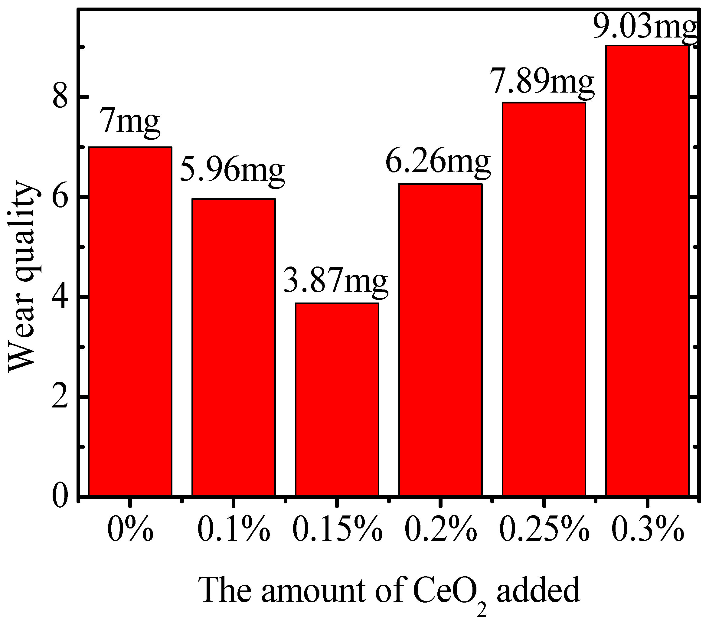
(4)
With the rise in CeO2 supplementation, the coating wear initially decreased before increasing, leading to enhancements in coating hardness and wear resistance. At a CeO2 supplementation level of 0.15%, wear decreased from 7.00 mg to 3.87 mg, marking a reduction of 3.13 mg, which is a 44.7% decrease compared to CuCrZr coating without CeO2 supplementation.
This study investigates the plasma cladding of CuCrZr-CeO2 coating on a CuCrZr rail gun. The incorporation of varying amounts of CeO2 is found to lower the friction coefficient of the CuCrZr-CeO2 coating, enhance its hardness, and boost the wear resistance of the electromagnetic rail gun rail gun.

Author Contributions

Conceptualization, Y.W. and H.X.; methodology, Y.W. and G.C.; software, Q.L.; validation, H.X., Z.Q. and X.Y.; formal analysis, Y.W.; investigation, G.C. and Q.W.; resources, Q.L.; data curation, C.L.; writing—original draft preparation, Y.W.; writing—review and editing, Y.W.; visualization, H.X.; supervision, H.X.; project administration, H.X.; funding acquisition, H.X. All authors have read and agreed to the published version of the manuscript.

Funding

This work was funded by the Youth Fund project of Hebei Provincial Education Department (QN2024248).

Data Availability Statement

Data are contained within the article.

Conflicts of Interest

The authors declare no conflicts of interest.

References

  1. Xiang, H.J.; Qiao, Z.M.; Lv, Q.A. Principle and Technology of Electromagnetic Railgun; Beijing Institute of Technology Press: Beijing, China, 2022. [Google Scholar]
  2. Lu, J.Y.; MA, W.M. Electromagnetic Orbital Launch Theory and Technology; Science Press: Beijing, China, 2020. [Google Scholar]
  3. Du, X.Y.; Liu, S.W.; Guan, J. Design and Performance Analysis of an Electromagnetic Railgun. J. Phys. Conf. Ser. 2022, 2378, 012008. [Google Scholar] [CrossRef]
  4. Liu, Z.Y. Preparation of Conductive Antifriction Coating for Electromagnetic Gun Armature and Study on Current-Carrying Friction Properties; Xiangtan University: Xiangtan, China, 2022. [Google Scholar]
  5. Lv, Q.A.; Xiang, H.J.; Lei, B.; Zhang, Q.; Zhao, K.Y.; Li, Z.Y. Physical Principle and Relevant Restraining Methods About Velocity Skin Effect. IEEE Trans. Plasma Sci. 2015, 43, 1523–1530. [Google Scholar]
  6. Lian, G.F.; Que, L.Z.; Cao, Q. Effect of CeO2 content on microstructure and properties of laser cladding Ni45A+TiC composite coating. Surf. Technol. 2019, 52, 448–456. [Google Scholar]
  7. Li, S.; Liu, D.F.; Liu, G.; Xin, S.W.; Deng, Z.; Li, C.; Chen, T. Study on the preparation of CeO2-doped AlCoCrFeNiTi high entropy alloy bioinert coatings by laser cladding: The effect of CeO2 particle size on the tribological properties of the coatings. Surf. Coat. Technol. 2023, 475, 130155. [Google Scholar] [CrossRef]
  8. Wang, X.; Yao, P.; Zhou, H.; Fan, K.; Deng, M.; Kang, L.; Yuan, Z.; Lin, Y. Research Progress on Surface Damage and Protection Strategies of Armature–Rail Friction Pair Materials for Electromagnetic Rail Launch. Materials 2024, 17, 277. [Google Scholar] [CrossRef] [PubMed]
  9. Zhang, B.; Shi, W.; Lin, Y.; Jiang, L.; Wang, L.; He, K. Effect of CeO2 Content on Microstructure and Wear Resistance of Laser-Cladded Ni-Based Composite Coating. Lubricants 2024, 12, 227. [Google Scholar] [CrossRef]
  10. Le, T.T.; Venugopal, I.P.; Truong, T.H.; Cao, D.N.; Le, H.C.; Nguyen, X.P. Effects of CeO2 nanoparticles on engine features, tribology behaviors, and environment. Energy Sources Part A Recovery Util. Environ. Eff. 2023, 45, 8791–8822. [Google Scholar]
  11. Prakash, S.D.; Shubham, S. Effect of CeO2–Ni addition on the behavior of AZ91-A356 based composite fabricated by friction solid state technique. Mater. Chem. Phys. 2024, 311, 128551. [Google Scholar]
  12. Ma, G.F.; Li, Z.P.; Zhao, X.R.; Wang, Z. Microstructure and corrosion-resisting properties of CeO2-SiO2-Al2O3 composite coatings prepared by plasma electrolytic oxidation on aluminum matrix composites. J. Alloys Compd. 2024, 1008, 176673. [Google Scholar] [CrossRef]
  13. Safari, A.; Mozammel, M.; Emarati, S.M.; Khalil-Allafi, J. Fabrication of a durable corrosion-resistant superamphiphobic CeO2–TiO2 ceramic nanocomposite coating on AZ31B Mg alloy by plasma electrolyte oxidation. Ceram. Int. 2024, 50, 34657–34669. [Google Scholar] [CrossRef]
  14. Hu, R.; Wang, R.D.; Zhang, J.; Zhang, C.; Zhang, Y.; Li, G.; Lu, X.; Yang, Y.; Liu, Q. An in-situ synthesised TiC/Ni60A composite coating on copper by plasma cladding. Mater. Sci. Technol. 2023, 39, 729–735. [Google Scholar] [CrossRef]
  15. Peng, Y.; Zhang, W.; Li, T.; Zhang, M.; Liu, B.; Liu, Y.; Wang, L.; Hu, S. Effect of WC content on microstructures and mechanical properties of FeCoCrNi high-entropy alloy/WC composite coatings by plasma cladding. Surf. Coat. Technol. 2020, 38, 125326. [Google Scholar] [CrossRef]
  16. Cao, L.; Xia, Y.; Cui, H.; Li, Q.; Zhu, B.; Wang, Q. Microstructural characteristics of TiB2–TiC–NiAl composite coatings via Plasma Cladding Process. Surf. Eng. 2019, 35, 997–1002. [Google Scholar] [CrossRef]
  17. Zhang, C.; Wang, R.; Hu, R.; Zhang, Y.; Wu, W.; Lu, X. Layer-by-layer analysis: Tribological behaviour of Ni60A coating on copper substrate prepared by plasma cladding. Mater. Sci. Technol. 2022, 17, 1467–1473. [Google Scholar] [CrossRef]
  18. Wei, S.Y.; Wang, C.M.; Peng, W.Y.; Luo, R.K.; Chen, Y.; Wan, Z.Z.; Jin, Y. Effects of process parameters and annealing on microstructure and properties of CoCrFeMnNi high-entropy alloy coating prepared by plasma cladding. China Foundry 2023, 6, 491–502. [Google Scholar] [CrossRef]
  19. Huang, Y.; Dong, S.; Lü, K.; Li, G.; Jiang, J.; Deng, L.; Chen, W.; Cao, X. Effects of CeO2 doping on the mechanical, infrared radiative, and thermophysical properties of Pr2Zr2O7 ceramics for potential thermal protective coatings. Ceram. Int. 2024, 50, 48862–48868. [Google Scholar] [CrossRef]
  20. Yang, C.; Jing, C.N.; Fu, T.L.; Lin, T.; Guo, W.; Liu, N. Effect of CeO2 on the microstructure and properties of AlCoCrFeNi2.1 laser cladding coatings. J. Alloys Compd. 2024, 976, 2948. [Google Scholar] [CrossRef]
  21. Meng, J.B.; Wang, S.K.; Guan, Q.Y.; Dong, X.; Li, L.; Yu, H.; Li, H. Fabrication and performance of composite coating doped with CeO2 nanoparticles by plasma electrolytic oxidation on Cu–Zn alloy surface. J. Appl. Electrochem. 2023, 53, 2347–2357. [Google Scholar] [CrossRef]
  22. Zhang, Y.; Sun, S.L.; Zhao, L.; Yang, C.D.; Wu, L.P.; Guo, Y.; Ang, A.S.M. Corrosion Behavior of Plasma-Sprayed Al2O3-3%TiO2 Coatings Doped with CeO2. J. Therm. Spray Technol. 2022, 32, 290–305. [Google Scholar] [CrossRef]
  23. Zhang, H.; Zhuang, J.; Li, J. The Effect of Laser-Cladded Co6, T400, and Ni-Based 30WC Coatings on the Wear Resistance of H13 Steel. Coatings 2024, 14, 114. [Google Scholar] [CrossRef]
Figure 1. (a) Particle size distribution of CuCrZr powder; (b) Microstructure of CuCrZr powder; (c) Microstructure of CeO2 powder.
Lubricants 12 00409 g001
Figure 2. CuCrZr-CeO2 coating comparison of real objects before and after cladding.
Lubricants 12 00409 g002
Figure 3. XRD pattern of CeO2 coatings with different contents.
Lubricants 12 00409 g003
Figure 4. (a) 0% CeO2 coating surface image; (b) 0.1% CeO2 coating surface image; (c) 0.15% CeO2 coating surface image; (d) 0.2% CeO2 coating surface image; (e) 0.25% CeO2 coating surface image; (f) 0.3% CeO2 coating surface image.
Lubricants 12 00409 g004
Figure 5. Different contents of CeO2 coating elements scanning. (a) 0.1% CeO2; (b) 0.15% CeO2; (c) 0.2% CeO2; (d) 0.25% CeO2; (e) 0.3% CeO2.
Lubricants 12 00409 g005
Figure 6. EDS scanning results of CeO2 coatings with different content (a) 0.1% CeO2; (b) 0.15% CeO2; (c) 0.2% CeO2; (d) 0.25% CeO2; (e) 0.3% CeO2.
Lubricants 12 00409 g006
Figure 7. Vickers hardness of six samples.
Lubricants 12 00409 g007
Figure 8. At 10 N load, the addition amounts of CeO2 are 0%, 0.1%, 0.15%, 0.2%, 0.25%, and 0.3% friction coefficients, respectively.
Lubricants 12 00409 g008
Figure 9. Load 10 N wear profile and wear volume.
Lubricants 12 00409 g009aLubricants 12 00409 g009b
Figure 10. Wear loss quality of CeO2 coatings with different content.
Lubricants 12 00409 g010
Figure 11. (a) 0% CeO2; (b) 0.1% CeO2; (c) 0.15% CeO2; (d) 0.2% CeO2; (e) 0.25% CeO2; (f) 0.3% CeO2 SEM for friction and wear marks.
Lubricants 12 00409 g011aLubricants 12 00409 g011b
Table 1. Main composition of CuCrZr rail (Wt%).
ZrCrCu
0.12%0.79%Bal.
Table 2. Main components of CuCrZr powder (Wt%).
ZrCrCu
0.1–0.25%0.7–0.8%Bal.
Table 3. Parameters of plasma cladding.
ParameterValue
Cladding modeHand cladding
Powder feeding methodPneumatic powder feed
Protective gas typeHigh purity argon
Cladding currentMain arc current 143
Ionic gas (L/min)2.5
Shielding gas velocity (L/min)5
Speed of powder gas delivery (L/min)2.8
The quantity of powder dispensed (g/min)280
Disclaimer/Publisher’s Note: The statements, opinions and data contained in all publications are solely those of the individual author(s) and contributor(s) and not of MDPI and/or the editor(s). MDPI and/or the editor(s) disclaim responsibility for any injury to people or property resulting from any ideas, methods, instructions or products referred to in the content.

