Abstract
Spiral bevel gears are extensively employed in mechanical transmissions; however, they are prone to adhesive wear when operating under high-speed and heavy-load conditions. Research indicates that the tooth surface roughness of gears significantly influences the friction and wear of the meshing gears. The present study delves into the origins of tooth surface roughness through the integration of the W-M function and fractal theory. Utilizing an involute helical gear with surface roughness for tooth cutting, a three-dimensional model is established with roughened tooth surfaces. This paper introduces an approach to developing three-dimensional gear models with roughness and applies the finite element method to perform thermodynamic analysis on gears exhibiting diverse levels of surface roughness. The thermal analysis of gears with varying degrees of roughness was conducted using the finite element method. Comparative analysis of the results under specific operating conditions elucidated the impact of roughness on tooth surface temperature rise. In order to validate the simulation model, an experimental test platform for spiral bevel gears of identical size was established. This model integrates tooth surface roughness with thermodynamic analysis, allowing for the rapid assessment of tooth surface temperature rise under different machining conditions, and reducing the cost of validating predicted tooth surface load-carrying capacity.
1. Introduction
A helicopter comprises a fuselage, three primary systems (lift, power, and transmission), and on-board flight equipment. Notably, the transmission system stands out as the crucial component [1]. The spiral bevel gear, a critical element in the transmission system, significantly influences the operational performance of the helicopter’s aero-engine [2].
During operation, the meshing surfaces of spiral bevel gears experience considerable power loss due to friction, normal forces, and high sliding speeds. Much of this lost power is converted into frictional heat, leading to a significant localized temperature increase on the gear tooth surfaces. This rise in temperature weakens the lubricant film between the meshing surfaces, eventually causing direct metal-to-metal contact, which can result in scuffing failure [3]. The microstructure of the spiral bevel gear tooth surface plays a key role in influencing the friction-induced temperature rise, which in turn affects the likelihood of scuffing. Therefore, studying the impact of surface roughness on the temperature distribution in spiral bevel gears is crucial.
Since the early 20th century, significant progress has been made in theoretical and simulation-based studies on rough surface modeling techniques. Patir [4] proposed a numerical method for generating 3D rough surfaces with specific statistical characteristics, utilizing a linear transformation of a random matrix to produce a Gaussian surface with a defined autocorrelation function. Ge [5] conducted individual measurements of surface profiles for various samples and examined the fractal properties of rough surfaces, introducing the concept of characteristic roughness. Meng et al. [6] combined the W-M function from fractal theory with the involute and helical equations of gears, using Matlab to simulate involute gear tooth profiles. Their findings showed a shift in surface morphology from being irregular to smoother as the fractal dimension increased. Han et al. [7] developed an accurate method for generating the microscopic morphology of curved bevel gear tooth surfaces. Sutyagin et al. [8] created a computer program to simulate contact between rough surfaces, determining the real contact area under load. Wang et al. [9] established a numerical model for rough surface contact with high computational accuracy, applying it to predict wear in spur gears. In the exploration of the temperature field of spiral bevel gears, establishing a three-dimensional finite element model for these gears proves challenging, and acquiring the contact stress on the tooth surface is not straightforward. Consequently, determining parameters, such as frictional heat flux density and other thermal properties, becomes intricate.
S et al. [10] conducted a numerical analysis to evaluate how fluid properties affect thermal behavior, validating their findings against experimental data. This work provides a dependable approach for investigating heat transfer. In another study, [11] proposed a method based on the finite element method (FEM) to examine the thermal behavior of spiral bevel gears, particularly focusing on frictional heat generation. This method can determine the distribution and variation of the actual temperature field of gears. Liu et al. [12] established a heat transfer model of spiral bevel gears and analyzed the temperature distribution during gear operation using the gear heat transfer model. Wang et al. [13] established a three-dimensional model of the gear based on the actual scattered point distribution of the gear tooth surface. They conducted thermal analysis to solve for the temperature field distribution of the tooth surface. The authenticity of the model was verified by comparing the simulation results with the experimental results. By using Loaded Tooth Contact Analysis (LTCA), they derived the key kinematic parameters of the tooth surface and used finite element analysis to assess the steady-state temperature distribution of a single gear tooth. Zhang et al. [14] introduced a coupled thermo-elasto-hydrodynamic analysis model, addressing the lubrication conditions on the tooth surface. This model overcomes the challenge of applying a dynamic heat source to an intricate spiral bevel gear surface, improving thermal analysis for spiral bevel gears. Cao et al. [15] investigated how the meshing path of spiral bevel gears affects various performance metrics, applying hybrid elastohydrodynamic lubrication and gear loading contact analysis principles. Lyu et al. [16] created a transient mixed elastohydrodynamic lubrication model for spiral bevel gears, using it to explore the mechanism of frictional thermal effects that contribute to scuffing failure.
In experimental analysis, Zhang et al. [17] performed two different shot peening treatments on carburized and quenched 17CrNiMo6 gear steel specimens to evaluate surface wear under varying treatments. Li et al. [18] proposed a wear model for spur gear contacts, developing a heat transfer equation to estimate the volumetric temperature of the gears. The frictional heat flux was examined using thermo-mixed elastohydrodynamic lubrication (EHL). Handschuh et al. [19] introduced a tribometer specifically designed for traction and wear tests, simulating gear contacts common in aerospace and automotive applications. Chen et al. [20] experimentally verified the load-carrying capacity and failure modes of gears under aerospace conditions, employing various surface treatments. Castro et al. [21] investigated how operating conditions, gear geometry, and base oil viscosity affect gear wear, using tests conducted on the FZG test rig.
The issue of heat transfer in scuffing should also consider the thermal elastohydrodynamic problem of the tooth surface. Simon V [22,23] studied the theoretical aspects of elastohydrodynamic lubrication (EHD) in gears.
From the reviewed literature, it is clear that much of the research focuses on gear scuffing or the effects of gear surface microstructures on various gear properties. However, a comprehensive theoretical framework and simulation method addressing the influence of surface roughness on scuffing has yet to be fully developed. In this study, we propose a method to model spiral bevel gears with varying surface roughness using fractal theory combined with finite element analysis. The findings highlight the impact of surface roughness on the frictional thermal behavior of spiral bevel gears. Additionally, a gear test rig is designed to validate the simulation results. Adhesive wear emerges as a key failure mode in gears, with the temperature rise in the tooth surface being a crucial factor influencing this wear. Efficient gear production with enhanced performance requires the quick and accurate validation of tooth surface temperature rise during manufacturing. This method accelerates the evaluation of how surface friction influences temperature rise, offering a cost-effective way to predict the adhesive bonding potential of spiral bevel gears manufactured using different machining processes. Moreover, it provides a theoretical basis for gear manufacturing processes.
2. Modeling of Spiral Bevel Gears with Different Surface Roughnesses
2.1. Simulation of Surface Profile Curves of Spiral Bevel Gears
The W-M function simulation method was utilized to generate rough surface profile curves that display fractal characteristics. This method offers the advantage of producing continuous curves with fractal properties, effectively representing the features of rough surfaces. The W-M function is expressed as follows [24]:
where x is the displacement coordinate of the contour, mm; z(x) is the height of the random contour of the rough surface, mm; D is the fractal dimension of the surface contour, generally taken as 1 < D < 2; G is the characteristic scale coefficient of the surface contour; γ is a constant greater than 1, for the random surface obeying the normal distribution, usually taken as γ = 1.5; γn denotes the spatial frequency of the rough surface contour; and nl is the number of the lowest cutoff frequency in the curve of the rough surface contour, usually taken as nl = 0, the number of the sequence of the rough surface contour. Equation (1) indicates that the W-M function is mainly determined by D, G, γ, and n. Usually, n = 0, 1, ……, 100 and γ = 1.5. The function only is affected by the fractal dimension and the characteristic scale factor.
In this study, we selected three types of spiral bevel gears, each produced using one of the three commonly used machining methods: unground machining, grinding, and polishing. The surface roughness of the gears, measured by the profile arithmetic mean deviation, was 0.8 μm, 0.4 μm, and 0.2 μm, respectively, for the gears manufactured using these methods.
Gao found the relationship among the fractal dimension, characteristic scale factor, and surface roughness [25], shown in the following equation:
Using the equations mentioned earlier and taking into account the roughness of the selected spiral bevel gears, Table 1 presents the fractal dimensions and characteristic scale factors corresponding to the surfaces of the gears with different levels of surface roughness.

Table 1.
Calculated data for surface fractal dimensions and eigen-scale coefficients.
The surface profile curves for spiral bevel gears with different roughness levels were simulated using Equation (1), as shown in Figure 1. With a decrease in surface roughness, the amplitude of the profile height reduces, and the distance between the peaks and valleys on the tooth surface also decreases. This results in a smoother, flatter gear surface profile.
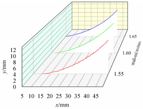
Figure 1.
Surface profile curves at different roughnesses.
2.2. Representation of Gear Involutes
The fundamental parameters of the spiral bevel gears in this paper are presented in Table 2. Each parameter of the spiral bevel gear can be computed using the corresponding relation equation.

Table 2.
Design parameters of spiral bevel gears.
Manufacture gears with different roughness levels using various machining techniques, as outlined in Table 3. Select the appropriate machining method according to the specified tooth surface roughness requirements.

Table 3.
Gear manufacturing methods.
The parameters of the cutting tool disk are crucial in the gear design and manufacturing process. Figure 2 provides the basic parameters of the gear cutting tool disk, laying the foundation for subsequent analysis.
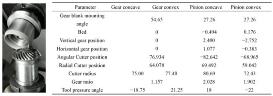
Figure 2.
Parameters of the gear cutting tool disk.
The involute equation for the tooth surface is based on previous studies [26]. By integrating the W-M function with this equation, the surface characteristics of spiral bevel gears with varying roughness can be determined. A three-dimensional model of the spiral bevel gear with defined roughness is then developed through the analysis of these formulas. The steps involved in creating this 3D model are illustrated in Figure 3.
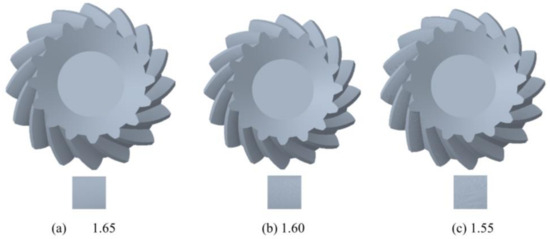
Figure 3.
Models of spiral bevel gears with different roughnesses.
Figure 4 presents the models of spiral bevel gears with varying surface roughness, along with the corresponding tooth surface topography. Surface roughness significantly influences the transmission performance of spiral bevel gears, making it essential to analyze the temperature rise of the tooth surfaces through finite element modeling.
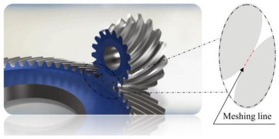
Figure 4.
Flash temperature contact diagram of tooth surface.
3. Thermal Analysis of Spiral Bevel Gears
Spiral bevel gears are crucial components in helicopter transmissions. Under heavy loads, they are susceptible to scuffing failure. The friction generated on the surface of the gears produces considerable heat, causing a rapid increase in temperature on the tooth surfaces, which can lead to severe scuffing. Flash temperature analysis is the most prevalent approach to studying tooth surface scuffing, with the Blok flash temperature method [27] being the most widely used. Figure 3 illustrates the Blok flash temperature model.
The main idea of using this method in this study is as follows:
Contact temperature refers to the sum of the bulk temperature of the contact surface and the flash temperature, where TMi is the bulk temperature and Tfl is the instantaneous flash temperature.
The maximum contact temperature refers to the sum of the bulk temperature of the contact surface and the maximum flash temperature, where TMi is the bulk temperature and Tflmax is the maximum instantaneous flash temperature. The likelihood of scuffing is predicted by comparing the maximum contact temperature with the critical value. The scuffing critical value is determined through gear scuffing tests. For bevel gears with band-shaped contact areas and tangential velocities parallel to each other, the flash temperature formula for the tooth surface is shown in Equation (6):
where μm is the average friction coefficient, XM is the thermo-elastic coefficient, XJ is the entrainment coefficient, is the load-sharing coefficient, is the end-face unit load (N/mm), is the normal unit load, BM1 is the pinion thermal contact coefficient, BM2 is the gear heat transfer coefficient, bH is half of the Hertzian contact area width, vg1 is the pinion tangential velocity, and vg2 is the gear tangential velocity.
The bulk temperature of the gear can be expressed as Equation (7):
Toil represents the lubricant oil temperature, and for oil-spray lubrication, Xs is 1.2. Xmp is a parameter that characterizes the number of gears in simultaneous mesh and can be expressed by Equation (8).
np is the number of pinion and gear pairs in simultaneous mesh. Here, it is taken as two.
The aforementioned method can be employed to calculate the flash temperature of the tooth surface during the operation of spiral bevel gears. Additionally, predicting the tooth surface temperature using finite element methods offers greater accuracy. This approach involves simulating the frictional heat generated at the gear meshing points.
The heat source during gear meshing is the frictional heat produced by the relative sliding of the tooth surfaces throughout the meshing process. Based on the principles of energy conservation and Fourier’s law, the differential equation governing the transient temperature field in the Cartesian coordinate system can be expressed as follows:
where T is the gear body temperature, °C, t is time, ρ is the density of the material, c is the thermal capacity of the material, k is the thermal conductivity of the material, W/(m·°C), and qv is the internal heat source strength of the gear.
In the bulk temperature field during the gear meshing process, the heat source is solely derived from the frictional heat between the tooth surfaces, resulting in qv = 0.
Additionally, since the bulk temperature field reaches a steady state, the temperature remains constant over time. Consequently, Equation (9) can be simplified to [28]
To solve the differential equation mentioned above, it is essential to establish the boundary conditions. During the operation of the gears, the contact environment varies for each surface. Different contact environments correspond to different heat exchange conditions, and the heat generated and transferred per unit time differs. Figure 5 shows the heat exchange conditions corresponding to different surfaces. Each contact surface corresponds to different descriptions, and the corresponding numbers for each contact surface are given in the figure below [29].
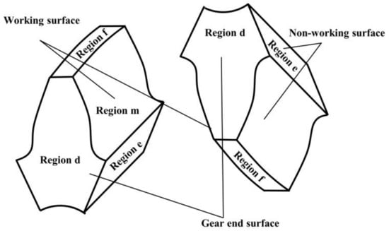
Figure 5.
Heat exchange conditions of different gear surfaces.
In the m-region
αm is the heat transfer coefficient for mixed lubrication on the gear surface during the experiment.
In the f-region
In the d-region
In the e-region
The above formulas provide the boundary conditions for each surface during the heat transfer process of spiral bevel gears. The heat transfer process involves heat generation from a specified heat source, and this heat is transferred to various surfaces through defined boundaries. Therefore, solving the heat exchange conditions for each contact surface using the above boundary conditions is crucial. The parameters mentioned above are all derived from previous research [26]. The transfer of frictional heat is the source of temperature variations across the contact surfaces of the gears.
According to our knowledge of heat transfer, it can be assumed that the heat equilibrium equation of the transient temperature field of gears that do not generate heat autonomously is the following program [30]:
After analyzing the steady-state temperature field of the tooth surface, it is necessary to analyze the transient temperature field. The two temperature fields share the same heat transfer conditions, so they will not be repeated here [29,30,31].
3.1. Calculation of Heat Transfer Coefficient for Gear Contact
The convective heat transfer coefficient in the actual running contact surface is calculated as follows [32,33]:
The convective heat transfer coefficient of a gear is an important parameter that describes the heat exchange capacity between the gear surface and the surrounding fluid (such as air or lubricating oil). It determines the rate of heat transfer between the gear surface and the fluid and is a key factor in analyzing the temperature field distribution and heat dissipation performance of the gear. Therefore, this paper provides a detailed calculation formula for the convective heat transfer coefficient. The convective heat transfer coefficient reflects the heat exchange efficiency between the gear surface and the fluid.
The heat transfer conditions for surfaces other than the contact surfaces are as follows [34,35]:
When the gear rotates, the tooth surface comes into contact with lubricating oil or air, generating frictional heat, which is transferred to the surrounding medium through convection. All the parameters of the above formulas are provided in previous studies [26].
During the simulation, only the heat exchange conditions between the contact surfaces are considered, while the heat exchange conditions of the remaining surfaces are neglected. This does not affect the simulation analysis of the maximum temperature of the tooth surface.
The influence of lubricating oil is considered when calculating the convective heat transfer coefficient of the tooth surface.
3.2. Heat Exchange Conditions under Different Lubrication Methods
Dry friction and mixed friction are two important friction states in the contact process of gears. Dry friction is prone to causing gear damage, while mixed friction helps to improve the performance and service life of gears. Understanding the characteristics and influencing factors of these two friction states is important for optimizing gear design and enhancing the efficiency of transmission systems.
The lubrication state has a significant impact on the heat exchange conditions of spiral bevel gears. Therefore, it is crucial to study the convective heat transfer coefficients of gears under different lubrication states. The convective heat transfer coefficients under dry friction and mixed lubrication can be calculated using the above formulas. Table 4 lists the basic parameters of the gear materials.

Table 4.
Basic parameters of gear materials.
3.3. Calculation of Frictional Heat
During the operation of the gear, there is mutual friction between the tooth surfaces. Relative sliding occurs between the two tooth surfaces. The heat generated by the friction becomes the sole heat source for the temperature rise in the tooth surfaces. The formula for the generated heat is as follows:
where Q represents the frictional heat flux in W/m2, and l is the length of the contact line. The friction coefficient f is set at 0.055 for the mixed lubrication state and 0.18 for dry friction [34]. The relative sliding speed v and the maximum contact stress P are obtained through finite element analysis. The frictional heat is calculated using the above formula.
After performing the calculations, the frictional heat flux density at the pinion’s meshing point under mixed lubrication, as shown in Figure 6, is determined. Thirteen contact points along the meshing line were carefully selected for heat flux density calculations. The frictional heat flux density at the pinion’s meshing point under dry friction conditions is also obtained and depicted in Figure 6.
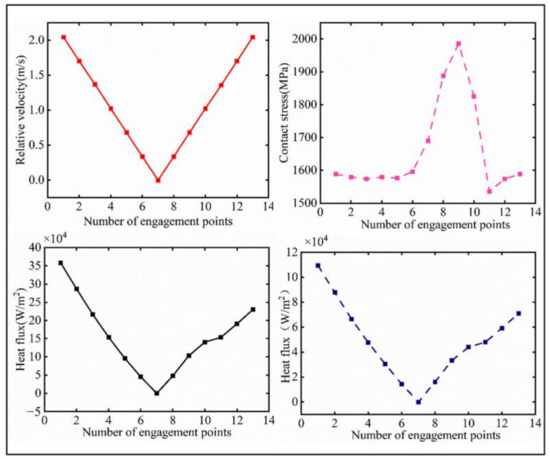
Figure 6.
The distribution of different factors along the meshing line.
Based on Equation (21), the key factors affecting the average frictional heat flux are the maximum Hertzian contact pressure, the friction coefficient, and the relative sliding speed. Since these factors are the focus of this paper, Figure 2 shows their distribution along the meshing line.
In Figure 5, the horizontal axis represents the normalized coordinates of the meshing line, with the relationship to the pressure angle at the meshing point explained in Gong et al. [36]. Using Matlab, the relative sliding velocity between the engaging tooth surfaces during the meshing process of the spiral bevel gear pair is computed. Figure 5 displays the relative sliding velocities at 13 contact points along the meshing trajectory of the driving gear, providing a foundation for frictional heat flux calculations. Additionally, Masta 14.0 software is used for loading contact analysis, offering insights into the engagement process of the gear pair. The meshing trajectory and the maximum contact stress at the 13 meshing points, as shown in Figure 5, are essential for determining the frictional heat flux.
4. Temperature Field Simulation of Spiral Bevel Gears
Firstly, a 3D model of the spiral bevel gear with smooth surface roughness and a different surface roughness can be established, as shown in Figure 7a; then, the 3D model of the spiral bevel gear is cut into single teeth in Solidworks 2018 software, as shown in Figure 7b; finally, the single-tooth model is imported into Workbench 2021R1 software to perform meshing, as shown in Figure 7c.

Figure 7.
Spiral bevel gear model.
4.1. Temperature Field in Steady State
Steady-state thermal analysis is conducted for the individual teeth of the spiral bevel gears, comparing smooth surfaces with surfaces of varying roughness characterized by different fractal dimensions, as shown in Figure 8. The resulting steady-state temperature fields for each tooth, along with temperature distribution curves across the tooth width, are presented. Additionally, plots illustrating the maximum and minimum steady-state temperatures for individual teeth with different fractal dimensions are generated.
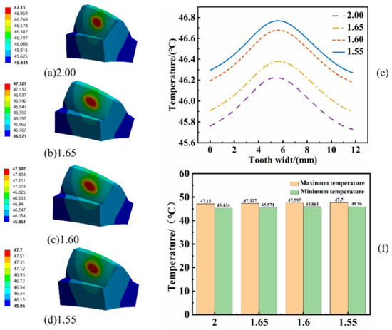
Figure 8.
(a–d) Tooth surface temperature rise under different roughnesses, (e) Temperature change in the direction of the tooth width, (f) Temperature range at different roughnesses.
From Figure 8, several observations can be made:
The peak temperature of a single tooth appears in the central region of the meshing surface due to the concentration of frictional heat flow in this area. The temperature within the tooth body is lower than in the meshing zone, but higher than at the gear’s end face, reflecting the heat input and dissipation capacity of the tooth face.
The steady-state temperature distributions for teeth with varying fractal dimensions are similar to those of smooth teeth (D = 2). However, the maximum steady-state temperature decreases as the fractal dimension increases. This occurs because higher fractal dimensions correlate with reduced surface roughness, which lowers the contact area during gear meshing and, as a result, reduces temperature.
The maximum tooth temperature increases by 1.16%, 0.95%, and 0.38% at fractal dimensions of 1.55, 1.60, and 1.65, respectively, compared to smooth teeth.
4.2. Temperature Field in Transient State
Lubrication conditions during the transient simulation were transitioned from mixed lubrication to dry friction in a spiral bevel gear. This paper addresses the computation of the transient temperature field for spiral bevel gears, utilizing the steady-state temperature field as the initial temperature distribution.
As illustrated in Figure 9, the transient temperature field of the pinion under smooth tooth surface conditions is obtained at various time intervals. Furthermore, the variation in temperature rise for an individual tooth within a 1200 s timeframe is determined. Observations from Figure 9 include the following:
- (1)
- The transient temperature field distribution of an individual tooth closely resembles that of the steady-state temperature field. Notably, the temperature at the end face of the single tooth is comparatively lower. The temperature within the body section of the tooth is higher than at the end face, but lower than on the meshing surface.
- (2)
- The maximum temperature on the meshing surface of the single tooth experiences a notable increase of 74.92 °C from 0 s to 1200 s.
- (3)
- Examining the temperature rise curve reveals distinct phases: initially, the maximum temperature of the single tooth rises sharply with increasing time, followed by a period where the rise becomes more gradual, and eventually stabilizes.
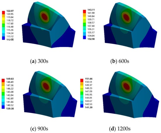
Figure 9.
Transient temperature field of single tooth of smooth tooth face (°).
Figure 10 illustrates the transient temperature field distribution of an individual tooth in a spiral bevel gear at 1200 s, considering fractal dimensions of 1.65, 1.6, and 1.55. The maximum temperatures of the gear teeth exhibit increases of 1.22%, 3.23%, and 4.00%, respectively, compared to those observed on a smooth tooth surface.
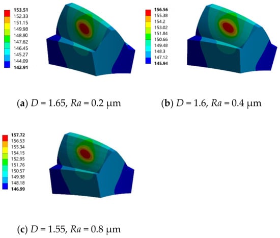
Figure 10.
Transient temperature field of tooth surface for a single tooth with different fractal dimensions and surface roughnesses at 1200 s (°).
The above are the simulation analysis results under different roughness levels. The simulation conditions correspond to the results under the load level 11, shown in Figure 11.
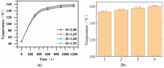
Figure 11.
Trend in transient maximum temperature of single tooth with different surface roughness. (a) Transient temperature curves at different roughnesses. (b) Transient temperature changes at different roughnesses.
The transient maximum temperature variation curves for spiral bevel gears with different fractal dimensions, specifically for a single tooth at 1200 s, are depicted in Figure 10. As the fractal dimension changes, the transient maximum temperature exhibits a continuous increase. The temperature experiences an initial sharp rise, and, over time, the growth rate gradually decelerates until it stabilizes. Figure 10b illustrates the variation in maximum temperature under different roughness levels. Figure 12 is a diagram of experimental equipment.
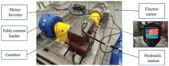
Figure 12.
Bevel gear test rig.
4.3. Experimental Validation
A test rig, depicted in Figure 12 and scaled to match, is established for the spiral bevel gear. The scuff experiment adheres to the ISO 6336-20/21 [37] standards, integrated with the consideration of actual conditions. The initial test temperature is set at 50 °C, determined by aligning with the steady-state results obtained from simulation analysis. The steps followed in determining this temperature are outlined in the literature [36].
The torque applied to the pinion is computed using Equation (22) [38]. Subsequently, the normal force is determined based on Equation (23). The experimental equipment was operated up to a load level of 14, as illustrated in Figure 13.
where T1 represents the torque applied during operation on the pinion (N·m), d1 is mentioned above, and u is the tooth number ratio. KA is the application coefficient, KV the dynamic load coefficient, Kγ is the load uniformity coefficient, KHα is the inter-tooth load distribution coefficient for contact strength calculations, and KHβ is the helix load distribution coefficient. ZH is the nodal region coefficient, ZE the elasticity coefficient, Zε the overlap coefficient for contact calculation, Zβ the helix angle coefficient, and ZB the single-tooth pair engagement coefficient.
where αn is the normal pressure angle in degrees (°), β is the helix angle in degrees (°).
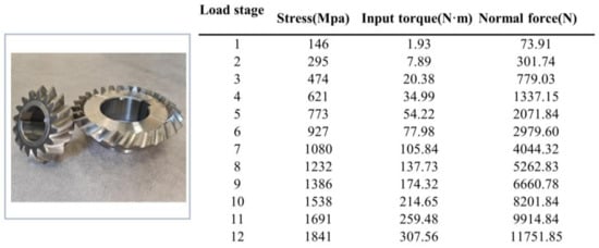
Figure 13.
Loaded load stage.
To validate the simulation results, an experiment is conducted using gears with a surface roughness of Ra 0.8 and oil injection lubrication. The experiment is designed to match the seven-stage loading condition used in the simulation analysis. The experimental setup for temperature measurement is shown in Figure 14.
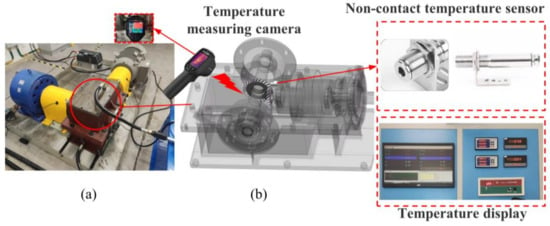
Figure 14.
(a) Test bench diagram (b) Temperature sensor position.
A Hikvon Microfilm infrared thermometer was used to measure the pinion temperature. At specified time intervals, the gearbox was promptly stopped and opened for temperature testing. The measurement results are shown in Figure 15.
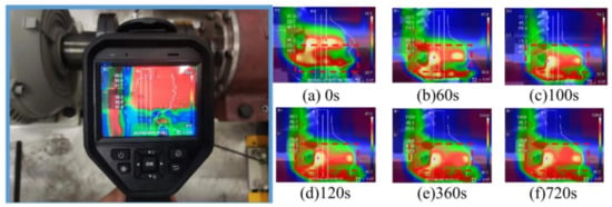
Figure 15.
Experimental temperature measurement.
The tooth surface temperatures were recorded at various time intervals (initial, 60 s, 100 s, 120 s, 360 s, and 720 s) for comparison with actual measurements. As shown in Figure 10, a significant temperature rise occurs at the meshing points of the tooth surfaces. The points with the fastest temperature increase correspond closely to the friction zones in the gearbox, confirming the accuracy of the contact path. The maximum error at these time points is 4.74%, as illustrated in Figure 16, indicating a strong correlation between the simulation and experimental results.
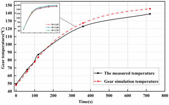
Figure 16.
Temperature comparison of the tooth surface between the simulation and the test.
5. Conclusions
A novel approach was introduced to explore the influence of tooth surface roughness on the temperature of spiral bevel gears by integrating fractal theory, meshing principles, and heat transfer analysis. Both steady-state and transient temperature fields were simulated, with key findings summarized as follows:
- Three-dimensional modeling of gears with roughness: A three-dimensional gear model, considering surface roughness, was established by combining the W-M function with the involute of spiral bevel gears. It was observed that reducing the fractal dimension increased surface fluctuation and roughness. Using these models, gears with varying roughness levels were generated.
- Temperature increase with roughness: The steady-state maximum tooth temperatures increased by 0.38%, 0.95%, and 1.16% at surface roughness values of 0.2 μm, 0.4 μm, and 0.8 μm, respectively. These results can help determine the initial oil temperature in scuffing tests.
- Validation with experiments: A comparison between simulation and experimental results showed a maximum error of 4.74%. Higher transient temperatures were observed with increasing fractal dimensions, confirming the model’s effectiveness in predicting.
Author Contributions
Methodology, Z.-J.C., X.-Q.Z., H.-Q.L., L.-N.W. and S.-W.Y.; Software, Z.-J.C., X.-Q.Z., S.-W.Y. and R.S.; Validation, Z.-J.C., X.-Q.Z. and R.S.; Formal analysis, X.-Q.Z., H.-Q.L. and R.S.; Investigation, L.-N.W.; Resources, Z.-J.C., S.-W.Y. and R.S.; Data curation, Z.-J.C., X.-Q.Z. and H.-Q.L.; Writing—original draft, L.-N.W.; Visualization, H.-Q.L. and L.-N.W.; Funding acquisition, Z.-J.C., S.-W.Y. and R.S. All authors have read and agreed to the published version of the manuscript.
Funding
This research was funded by [China Aviation Development Innovation Special Fund Project] grant number [No. KY-1003-2021-0020].
Data Availability Statement
The datasets generated during the current study are available from the corresponding author on reasonable request.
Conflicts of Interest
The authors declare no conflicts of interest.
References
- Zhao, Z.; Yang, Y.; Han, H.; Ma, H.; Wang, H.; Li, Z. Meshing characteristics of spur gears considering three-dimensional fractal rough surface under elastohydrodynamic lubrication. Machines 2022, 10, 705. [Google Scholar] [CrossRef]
- Hu, X.; Jiang, Y.; Luo, C.; Feng, L.; Dai, Y. Churning power losses of a gearbox with spiral bevel geared transmission. Tribol. Int. 2019, 129, 398–406. [Google Scholar] [CrossRef]
- Li, W.; Pang, D.; Hao, W. Effects of the helix angle, the friction coefficient and mechanical errors on unsteady-state temperature field of helical gear and thermal sensitivity analysis. Int. J. Heat Mass Transf. 2019, 144, 118669. [Google Scholar] [CrossRef]
- Patir, N. A numerical procedure for random generation of rough surfaces. Wear 1978, 47, 263–277. [Google Scholar] [CrossRef]
- Ge, S.R. Study on fractal characterization and fractal representation of rough surfaces. J. Tribol. 1997, 1, 74–81. [Google Scholar]
- Meng, F.; Xia, H.; Zhang, X.; Wang, J.; Jin, Y. Study on nonlinear dynamic characteristics of gear system with 3D anisotropic rough tooth surface based on fractal theory. Int. J. Non-Linear Mech. 2023, 150, 104366. [Google Scholar] [CrossRef]
- Ding, H.; Li, Y.; Zhao, Q.; Lu, S.; Rong, K.; Sun, J.; Hu, Z. On micro flank geometric topography design for spiral bevel and hypoid gears. Mech. Mach. Theory 2023, 183, 105236. [Google Scholar] [CrossRef]
- Sutyagin, O.V.; Bolotov, A.N.; Rachishkin, A.A. Computer simulation of the contact of rough surfaces. J. Frict. Wear 2016, 37, 198–203. [Google Scholar] [CrossRef]
- Wang, H.; Zhou, C.; Wang, H.; Hu, B.; Liu, Z. A novel contact model for rough surfaces using piecewise linear interpolation and its application in gear wear. Wear 2021, 476, 203685. [Google Scholar] [CrossRef]
- Modaresahmadi, S.; Khalesi, J.; Li, K.; Bird, J.Z.; Williams, W.B. Convective heat transfer analysis of a laminated flux focusing magnetic gearbox. Therm. Sci. Eng. Prog. 2020, 18, 100552. [Google Scholar] [CrossRef]
- Handschuh, R.F.; Kicher, T.P. A Method for thermal analysis of spiral bevel gears. J. Mech. Des. 1996, 118, 580–585. [Google Scholar] [CrossRef]
- Liu, S.; Liu, Z.; Lyu, Y. Investigation Into the Temperature Field and Thermal Deformation of a Spiral Bevel Gear Pair at Different Rotational Speeds. In Turbo Expo: Power for Land, Sea, and Air; American Society of Mechanical Engineers: New York, NY, USA, 2018; Volume 51098, p. V05BT18A003. [Google Scholar]
- Wang, Z.; Zheng, P. Thermal Elastohydrodynamic Lubrication and Efficiency of Grease Lubricated Spiral Bevel Gears. Tribology 2023, 44, 323–334. [Google Scholar]
- Zhang, J.; Liu, S.; Fang, T. Determination of surface temperature rise with the coupled thermo-elasto-hydrodynamic analysis of spiral bevel gears. Appl. Therm. Eng. 2017, 124, 494–503. [Google Scholar] [CrossRef]
- Cao, W.; Pu, W.; Wang, J.; Xiao, K. Effect of contact path on the mixed lubrication performance, friction and contact fatigue in spiral bevel gears. Tribol. Int. 2018, 123, 359–371. [Google Scholar] [CrossRef]
- Lyu, B.; Meng, X.; Zhang, R.; Wen, C. A deterministic contact evolution and scuffing failure considering lubrication deterioration due to temperature rise under heavy loads. Eng. Fail. Anal. 2021, 123, 105276. [Google Scholar] [CrossRef]
- Zhang, J.; Li, W.; Wang, H.; Song, Q.; Lu, L.; Wang, W.; Liu, Z. A comparison of the effects of traditional shot peening and micro-shot peening on the scuffing resistance of carburized and quenched gear steel. Wear 2016, 368, 253–257. [Google Scholar] [CrossRef]
- Li, S.; Kahraman, A. A scuffing model for spur gear contacts. Mech. Mach. Theory 2021, 156, 104161. [Google Scholar] [CrossRef]
- Handschuh, M.J.; Kahraman, A.; Anderson, N.E. Development of a high-speed two-disc tribometer for evaluation of traction and scuffing of lubricated contacts. Tribol. Trans. 2020, 63, 509–518. [Google Scholar] [CrossRef]
- Chen, T.; Wei, P.; Zhu, C.; Zeng, P.; Li, D.; Parker, R.; Liu, H. Experimental Investigation of Gear Scuffing for Various Tooth Surface Treatments. Tribol. Trans. 2023, 66, 35–46. [Google Scholar] [CrossRef]
- Castro, J.; Seabra, J. Global and local analysis of gear scuffing tests using a mixed film lubrication model. Tribol. Int. 2008, 41, 244–255. [Google Scholar] [CrossRef]
- Simon, V. Influence of misalignments on EHD lubrication in hypoid gears. In Proceedings of the International Design Engineering Technical Conferences and Computers and Information in Engineering Conference, Las Vegas, NV, USA, 4–7 September 2007; Volume 48086, pp. 671–680. [Google Scholar]
- Simon, V. Minimization of the influence of misalignments on EHD lubrication in face-hobbed spiral bevel gears. In Proceedings of the International Design Engineering Technical Conferences and Computers and Information in Engineering Conference, Portland, OR, USA, 4–7 August 2013; American Society of Mechanical Engineers: New York, NY, USA, 2013; Volume 55928, p. V005T11A037. [Google Scholar]
- Liu, J.; Ma, C.; Wang, S.; Wang, S.; Yang, B. Thermal contact resistance between bearing inner ring and shaft journal. Int. J. Therm. Sci. 2019, 138, 521–535. [Google Scholar] [CrossRef]
- Zhu, H.; Ge, S.; Huang, X.; Zhang, D.; Liu, J. Experimental study on the characterization of worn surface topography with characteristic roughness parameter. Wear 2003, 255, 309–314. [Google Scholar] [CrossRef]
- Cai, Z.J.; Zheng, X.Q.; Lan, H.Q.; Wang, L.N.; Yang, S.W.; Sheng, R. Time-Varying Meshing Stiffness and Dynamic Parameter Model of Spiral Bevel Gears with Different Surface Roughness. Appl. Sci. 2024, 14, 1533. [Google Scholar] [CrossRef]
- Blok, H. The postulate about the constancy of scoring temperature. NASA Spec. Publ. 1970, 237, 153. [Google Scholar]
- Wang, T. Study on the Steady-State Temperature Field of Spiral Bevel Gears; Northwestern Polytechnical University: Xi’an, China, 1999. [Google Scholar]
- Luo, B.; Li, W. Influence factors on bulk temperature field of gear. Proc. Inst. Mech. Eng. Part J J. Eng. Tribol. 2017, 231, 953–964. [Google Scholar] [CrossRef]
- Yan, Y.; Sun, L. Transient thermal analysis of spiral bevel gears under loss of lubrication. Appl. Mech. Mater. 2010, 1021, 566–570. [Google Scholar] [CrossRef]
- Xue, J.H. The Research on Thermal Behavior and the Modification Design of High-Speed and Heavy Power Gear System; University of Science and Technology Beijing: Beijing, China, 2015. [Google Scholar]
- Hu, X.; Yuan, Y.; Chen, J. Study on Temperature Field Distribution of a High-Speed Double-Helical Gear Pair with Oil Injection Lubrication. Lubricants 2024, 12, 315. [Google Scholar] [CrossRef]
- Shao, S.; Zhang, K.; Yao, Y.; Liu, Y.; Yang, J.; Xin, Z.; He, K. A Study on the Lubrication Characteristics and Parameter Influence of a High-Speed Train Herringbone Gearbox. Lubricants 2024, 12, 270. [Google Scholar] [CrossRef]
- Hartnett, J.P.; Deland, E.C. The influence of Prandtl number on the heat transfer from rotating non-isothermal disks and cones. Trans. ASME J. Heat Transf. 1961, 83, 95–96. [Google Scholar] [CrossRef]
- Dorfman, L.A. Hydrodynamic Resistance and the Heat Loss of Rotating Solids; Oliver and Boyd: Edinburgh, UK, 1963; pp. 150–230. [Google Scholar]
- Gong, M.Y.; Chen, S.C.; Wang, Y.J. Strength Calculation and Structure Design of Involute Cylindrical Gear; China Machine Press: Beijing, China, 1986. [Google Scholar]
- ISO 6336-21:2017; Calculation of Load Capacity of Spur and Helical Gears. Calculation of Scuffing Load Capacity (also Applicable to Bevel and Hypoid Gears). ISO: Geneva, Switzerland, 2017.
- Chen, T.; Zhu, C.; Liu, H.; Wei, P.; Zhu, J.; Xu, Y. Simulation and experiment of carburized gear scuffing under oil jet lubrication. Eng. Fail. Anal. 2022, 139, 106406. [Google Scholar] [CrossRef]
Disclaimer/Publisher’s Note: The statements, opinions and data contained in all publications are solely those of the individual author(s) and contributor(s) and not of MDPI and/or the editor(s). MDPI and/or the editor(s) disclaim responsibility for any injury to people or property resulting from any ideas, methods, instructions or products referred to in the content. |
© 2024 by the authors. Licensee MDPI, Basel, Switzerland. This article is an open access article distributed under the terms and conditions of the Creative Commons Attribution (CC BY) license (https://creativecommons.org/licenses/by/4.0/).
