Article

Study on the Dynamic Characteristics of Gears Considering Surface Topography in a Mixed Lubrication State

1
School of Mechanical Engineering, Chongqing Industry Polytechnic College, Chongqing 401120, China
2
College of Mechanical and Vehicle Engineering, Chongqing University, Chongqing 400044, China
3
Whole Design Department of Beijing Space Aircraft, China Academy of Space Technology, Beijing 100094, China
4
Shandong INVES Intelligent Equipment Co., Ltd., Zibo 255086, China
*
Author to whom correspondence should be addressed.
Lubricants 2024, 12(1), 7; https://doi.org/10.3390/lubricants12010007
Submission received: 18 November 2023 / Revised: 19 December 2023 / Accepted: 19 December 2023 / Published: 27 December 2023
(This article belongs to the Special Issue Friction–Vibration Interactions)

Abstract

:
Based on mixed lubrication analysis, considering the influence of rough interface contact stiffness, contact damping, and interface friction on the gear transmission system, the relationship between interface contact and the overall performance of the gear transmission system has been established. First, the surface topography is characterized using statistical parameters of rough surfaces, and the contact stiffness and damping for tooth surfaces with different roughnesses are calculated. Subsequently, a six degree of freedom gear tribo-dynamics coupling model is developed. Finally, the established tribo-dynamics model is employed to investigate the relationship between surface roughness and the overall performance of the gear transmission system. This study provides a more intimate connection between the contact interface and the general behavior of the gear transmission system, enabling a better representation of real-world engineering problems. The research findings reveal that contact stiffness and damping decrease with increasing surface roughness. Higher roughness leads to greater gear vibration amplitude. Moreover, elevated surface roughness results in intensified meshing force and more significant energy loss. Surprisingly, when the roughness is appropriate, gears with rough surfaces lose less energy than those with smooth surfaces.

1. Introduction

Analyzing the lubrication properties of surface contact is fundamental to discussing gear transmissions’ dynamic characteristics and energy loss. Wang and Cheng [1] established a numerical solution model that can predict the minimum film thickness during gear meshing. Hua and Khonsari [2], under the assumption of smooth gear surfaces, solved the transient elastohydrodynamic lubrication equation for straight gears. Many scholars have also conducted research on gear lubrication, with a focus on the analysis of oil film thickness and other factors. Shi et al. [3] found a solution to the lubrication state of low-speed heavy-duty gears and proposed parameter optimization selection principles based on the obtained results of gear surface oil film thickness and load-bearing capacity. Zhang and Mei [4] studied the elastic fluid lubrication problem of straight gears under non-steady-state conditions, and their research showed that the non-steady-state parameters during the gear meshing process are key factors affecting the central oil film thickness. Yi and Wang [5] studied the lubrication characteristics of gears under the influence of non-Newtonian fluid properties. Chang et al. [6] have researched the lubrication of tooth surfaces with groove textures to reduce friction. In recent years, research on gear lubrication has further expanded to encompass thermal elastohydrodynamic lubrication [7,8] and the study of lubricants [9,10]. Sivayogan et al. [11] have further studied the transient non-Newtonian elastohydrodynamics of rough meshing tooth surfaces under complex contact kinematics. From the literature review, it can be seen that basic research on gear lubrication characteristics has been relatively well-established.
Many researchers extended the study to investigate lubrication interface tribology properties and the stiffness and damping of lubricant films. Wang et al. [12], under the assumption of Newtonian fluids, researched the effect of heat transfer on the friction coefficient of gear lubrication interfaces. Lu and Cai [13] obtained the variation in lubricant film and pressure and corresponding friction coefficients during gear meshing using an elastohydrodynamic lubrication model for non-Newtonian fluids. Guilbault and Lalonde [14] derived formulas for calculating damping during gear meshing. Zhang et al. [15] used elastohydrodynamic lubrication theory to calculate the oil film stiffness and damping at gear contact interfaces and analyze their response to changing parameters. Some scholars [16,17] developed normal, tangential, and equivalent models for gear lubrication interface oil film stiffness and damping. Lastly, Xiao [18] researched the oil film stiffness of shaped gears through elastohydrodynamic lubrication theory.
The preceding analysis of gear lubrication friction and stiffness/damping was primarily based on the assumption of elastohydrodynamic lubrication. However, surface roughness must be addressed in practical engineering scenarios, making mixed lubrication familiar. Several scholars have delved into research related to mixed lubrication. Castro et al. [19] developed a formula for calculating the coefficient of friction under mixed lubrication conditions by establishing a relationship between load ratio and film thickness ratio. They analyzed changes in the coefficient of friction at the contact interface during gear meshing. They conducted experiments to compare the experimental results with the calculated ones, thereby validating the model’s effectiveness. Ouyang et al. [20] employed a three-dimensional contact mixed lubrication model to study the oil film and pressure distribution and the corresponding friction coefficient of involute cylindrical gears under different speeds and surface roughness. Li and Kahraman [21] constructed a model for transient mixed elastohydrodynamic lubrication analysis of involute gears, taking into account real surface topography. They examined the effects of various parameters on lubrication during gear meshing. More recently, Chimanpure et al. [22] further advanced the field by developing a non-Newtonian fluid transient mixed elastohydrodynamic lubrication model suitable for helical gears, enhancing the understanding of gear mixed lubrication. Building upon previous work, Cheng et al. [23,24] proposed a method for determining the contact stiffness and damping of involute gears under mixed lubrication conditions. Wang et al. [25] calculate and analyze the contact stiffness and damping of bevel gears under mixed lubrication conditions.
The stiffness, damping, and friction coefficient of gear transmission systems are directly influenced by the lubricants and asperity contact, leading to changes in the overall performance, including the dynamic characteristics, transmission efficiency, and fatigue failure properties of gears. Li et al. [26,27] established a relatively complete tribo-dynamic model for gears under mixed lubrication conditions to study dynamic characteristics, and based on this, they analyzed the energy loss and contact fatigue of gears. In the case of considering lubrication, the effects of contact stiffness and contact damping on gear dynamics cannot be ignored. For example, Ankouni et al. [28] and Guilbault [14] studied gear dynamic characteristics based on the analysis and calculation of oil film damping, while Xiao et al. [29] not only considered damping but also included contact stiffness in their research scope, discussing its impact on gear dynamic characteristics. Cao et al. [30,31] established a tribo-dynamics model of bevel gears based on the theory of mixed elastohydrodynamic lubrication and analyzed the effects of tribology properties on gear dynamics and contact fatigue by solving the lubrication characteristics of bevel gears. Recent studies [32,33] have investigated the influence of asperity distribution and other micro-surface topography on gear dynamics. Some new research [34,35,36] on surface texture and tribo-dynamics of journal bearings provides new ideas for subsequent work, in which we can delve into the discussion about the impact of surface texture during the analysis of gear tribo-dynamics. Gupta et al. [37] have studied the influence of lubricant additives on gear friction dynamics, taking into account surface textures. The study of gear friction dynamics is one of the current research hotspots, with numerous related research findings [38,39,40,41,42,43,44]. Based on the above survey results, in recent years, the analysis and research of tooth surface tribology properties and the tribo-dynamics research developed from that place have received extensive attention from scholars. The tribo-dynamics models, as mentioned above, can conduct an in-depth examination of the impacts brought by specific factors or parameters while also effectively bridging tribology with dynamics. However, the study of gear dynamics, considering both lubricant contact and asperity contact, remains insufficient. This paper aims to address the gaps in this particular research area.

2. Gear Stiffness and Damping under Mixed Lubrication Consideration

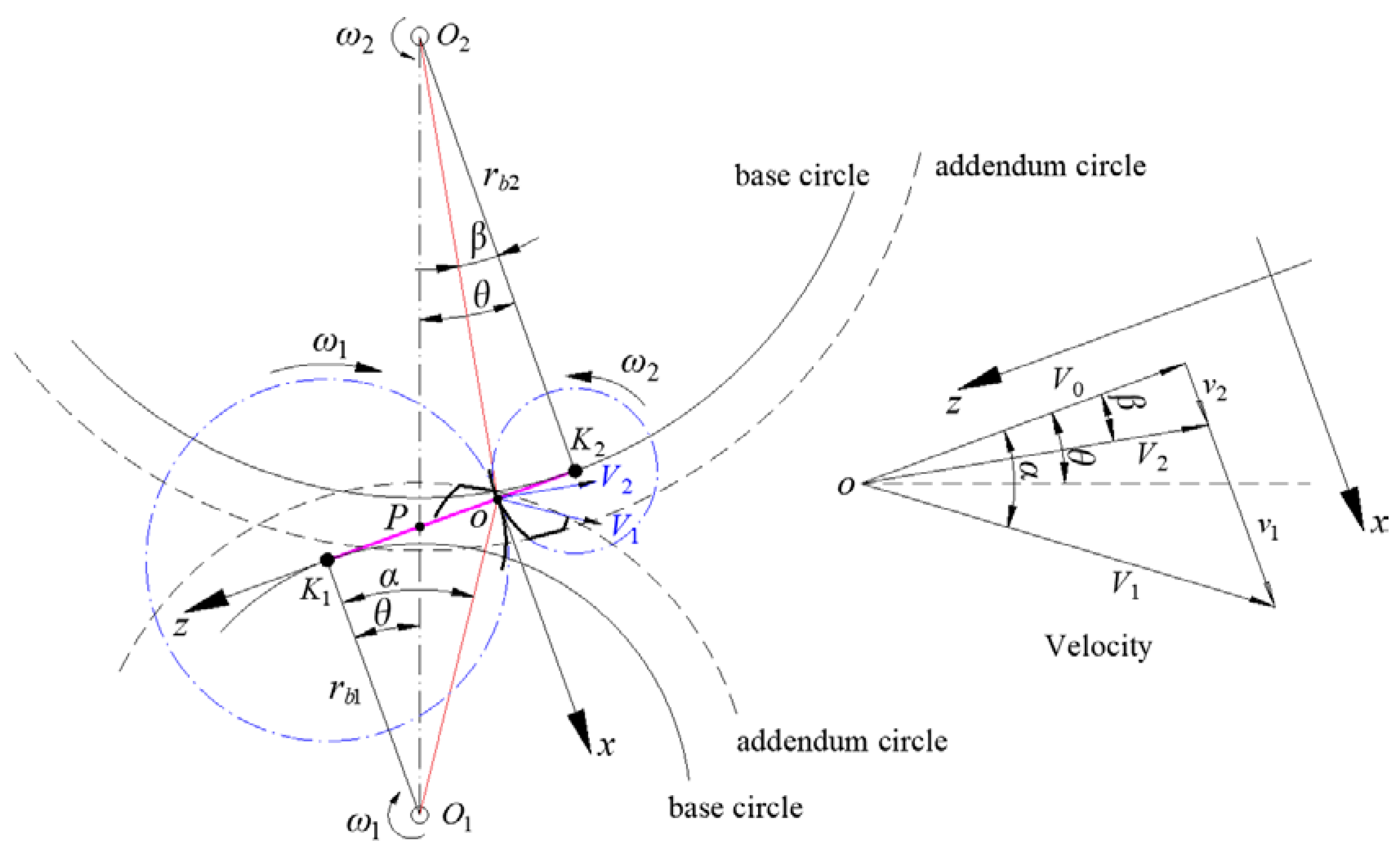
2.1. Gear Parameters and Lubrication Analysis

When the parameters of the rough surface (E, H, and σ) and tribology analysis (F, v, η, ρ, and re) at each contact point during gear engagement are established, the contact stiffness and damping in the process of gear meshing can be computed using the developed model [24]. The main variables that change over time during gear engagement are the meshing force, velocity, and radius of curvature. These parameters should be initially calculated and discussed. The load-sharing coefficients for these engaged tooth pairs can be determined through research conducted by Sánchez et al. [45], while velocity and radius of curvature can be obtained through gear meshing motion parameter analysis. The results have been listed in Appendix A.
Upon acquiring the various parameters during the gear meshing process, we can proceed to conduct optimized lubrication friction calculations. For real surface topology, a three-dimensional linear contact model should be used for lubrication solutions [46]. The primary control equations for calculating lubrication and friction are also listed in Appendix A.

2.2. Calculation of Stiffness and Damping

For engaged gear pairs, the oil film contact damping formula presented by Guillbault et al. [14] applies to smooth gear surfaces:
c g = 8 η b 3 w h c 3 ,
where b is the Hertzian half-width of the contact region, and hc represents the average film thickness. Considering the impact of asperity contact and the fact that lubricant only exists on part of the entire surface, the damping calculation expression is adjusted accordingly as follows:
C l = ( 1 λ ) c g = ( 1 λ ) 8 η b 3 w h c 3 ,
where λ is the ratio of actual contact area to apparent contact area (asperity contact ratio). When considering mixed lubrication, refer to reference [24] to compute contact stiffness and damping. We can obtain the following formulas for computing the total contact stiffness and contact damping:
K h = K s + K l = ψ A n [ h y s h y s + δ 1 k e ϕ ( z ) d z + h y s + δ 1 h y s + δ 2 k e p ϕ ( z ) d z + h y s + δ 2 k p ϕ ( z ) d z ] + A n ( 1 λ ) B h ,
C h = ( 1 ξ m K s + h 3 ( 1 λ ) 8 η b 3 w ) 1 .
Based on the calculation models of contact stiffness and damping during gear engagement introduced above, we can further establish the models of gear mesh stiffness and damping under mixed lubrication conditions. There are many calculation models for gear stiffness. The potential energy method presented by Yang and Lin [47] is both concise and efficient, making it a widely used calculation approach. As illustrated in Figure 1, the forces F acting on gears during engagement can be determined using the following expressions for the bending stiffness Kb, shear stiffness Kt, and compressive stiffness Ka:
1 K b = 0 d ( x cos α 1 h x sin α 1 ) 2 E I x d x ,
1 K s = 0 d 1.2 cos 2 α 1 G A x d x ,
1 K a = 0 d 1.2 sin 2 α 1 E A x d x .
In the equations, E represents Young’s modulus, while Ix, Ax, and G denote moments of inertia, area moments, and shear module of the gear, which are calculated as follows:
I x = 2 3 h x 3 w ,
A x = 2 h x w ,
G = E 2 ( 1 + ν ) .
During engagement, the presence of fillet radii at tooth roots and micro-deformations of the gear body both affect mesh stiffness. Calculating the gear stiffness that takes into account fillets and base deformation is quite complex. According to Sainsot et al. [48], the empirical formula for calculating the stiffness Kf caused by fillets and base deformation is:
1 K f = cos 2 α m w E L ( u f S f ) 2 + M ( u f S f ) + P ( 1 + Q tan 2 α m ) ,
where αm denotes the pressure angle, uf represents the distance from the point of engagement to the root radius, and sf refers to the radius of the root fillet. L*, M*, P*, and Q* are coefficients determined by gear geometric parameters, the values of which are detailed in the literature [48] and thus not repeated here. The total mesh stiffness, considering the effects of root fillets and base deformation, is expressed as:
K m = 1 / ( 1 K b 1 + 1 K t 1 + 1 K a 1 + 1 K f 1 + 1 K b 2 + 1 K t 2 + 1 K a 2 + 1 K f 2 + 1 K h ) .
It should be noted that in the above equation, subscripts 1 and 2 refer to the wheel and pinion, respectively, and Kh represents the contact stiffness. Taking into account surface deformations due to Hertzian contact, it can be said that:
K h = π E w 4 ( 1 ν 2 ) .
From Formula (13), it can be inferred that if only tooth surface deformation is considered, the contact stiffness is determined by material properties and tooth width. Therefore, when the gear parameters are determined, the stiffness becomes invariant. However, if the effects of asperity contact and lubrication are taken into account, the contact stiffness will be represented by Formula (3) instead. Under this condition, the gear contact stiffness is time-varying, and as a result, the total meshing stiffness Km would also become a time-varying quantity.
Meshing damping of gears can also be decomposed into two parts, one part being the damping of the overall system of engaged gears, while the other part refers to the damping generated from tooth surface contact, i.e., the contact damping under mixed lubrication mentioned previously. The total mesh damping can be expressed as:
C m = C s y s + C h .
System damping is typically directly related to the corresponding stiffness, and its calculation formula is:
C s y s = 2 ζ m 1 m 2 m 1 + m 2 K ¯ s y s ,
where ζ is the damping factor, a constant coefficient determined by the material. m1 and m2 represent the masses of the two engaged gears, respectively, and K ¯ sys represents the average value of the system engagement stiffness Ksys. It should be noted that the stiffness Ksys represents the stiffness of the gear engagement system without considering the contact stiffness:
K s y s = 1 / ( 1 K b 1 + 1 K t 1 + 1 K a 1 + 1 K f 1 + 1 K b 2 + 1 K t 2 + 1 K a 2 + 1 K f 2 ) .
To discuss the influence of the real surface topography of gear teeth on gear dynamics, it is also necessary to obtain the microscopic topography of the tooth surface. According to the research of Bakolas [49], we can obtain a rough surface, as shown in Figure 2.

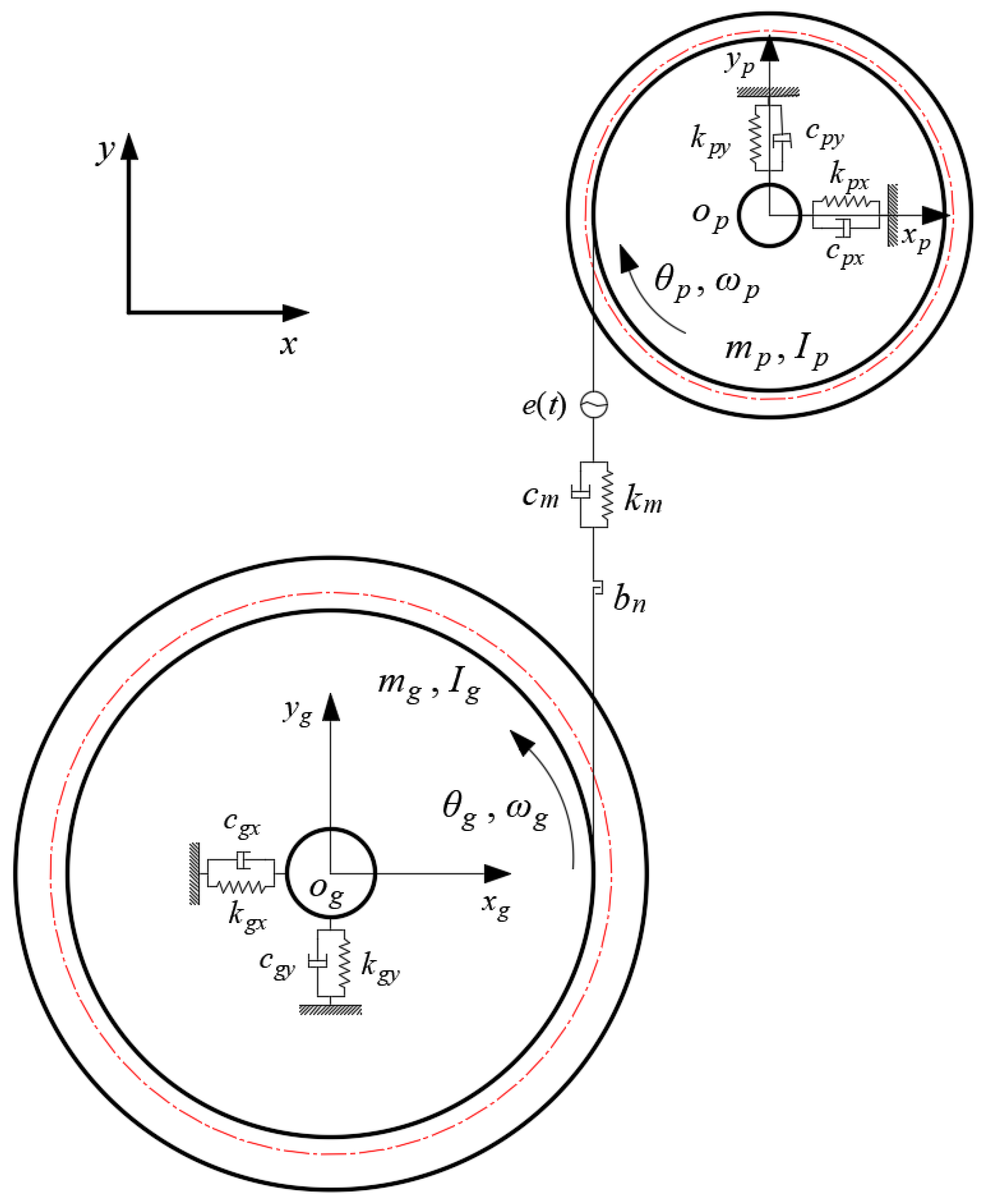
3. The Dynamics Model of Gears and Its Energy Dissipation

Taking into account lubrication and surface roughness, calculate the gear meshing stiffness and damping, then determine the friction coefficient of the gear surface. Subsequently, discuss the dynamic characteristics of gears while also calculating the energy loss caused by friction on the gear surface.
In this paper, a six degree of freedom dynamic model, as shown in Figure 3, is adopted. The gear is replaced by a rigid disk, and the subscripts p and g are used to identify the physical quantities related to the driving gear and driven gear, respectively. The mass and moment of inertia of the gear pair are denoted by m and I, while the angular position and velocity are denoted by θ and ω. The engagement between gears is modeled using stiffness km and damping cm along the meshing line. It should be noted that these values represent periodic changes under mixed lubrication conditions, taking into account factors such as dynamic transmission errors e resulting from the processing and installation of the gear pair as well as side clearance bn during the meshing process. The gear base is supported by a pair of spring-damping elements, with kx and cx representing stiffness and damping in the x-direction and ky and cy representing stiffness and damping in the y-direction. These elements represent the supporting effect of the shaft and bearing on the gear. Since torsion needs to be considered, the torsional stiffness kθ and torsional damping cθ of the support shaft must also be included in the overall dynamics system. Assuming a load torque Tg is applied, the following set of equations can be obtained based on Figure 3:
m p x ¨ p + c p x x ˙ p + k p x x p = F f 1 + F f 2 m p y ¨ p + c p y y ˙ p + k p y y p = F m 1 + F m 2 I p θ ¨ p + c p θ θ ˙ p + k p θ θ p = F m 1 + F m 2 r b p F f 1 L p 1 + F f 2 L p 2 m g x ¨ g + c g x x ˙ g + k g x x g = F f 1 + F f 2 m g y ¨ g + c g y y ˙ g + k g y y g = F m 1 + F m 2 I g θ ¨ g = F m 1 + F m 2 r b g F f 1 L g 1 + F f 2 L g 2 T g .
In addition to the parameters mentioned above, in the equation, rbp and rbg represent the base circle radius, x and y denote the displacement along the coordinate axis, i = one, two identifies the meshing gear pair, Fmi represents the dynamic meshing force of the gear, and Ffi denotes the frictional force on the gear surface. Lpi and Lgi represent the arm length of friction torques of the driving gear and driven gear, respectively.
During the engagement process, the actual flank clearance at the point of contact varies with displacement, so the function expression during engagement is:
f b ( Y ) = Y 1 2 b n , Y > 1 2 b n 0 ,                                             1 2 b n < Y < 1 2 b n Y + 1 2 b n , Y < 1 2 b n ,
where Yi denotes the dynamic transmission error during gear engagement. As a dynamic variable, its physical meaning is the difference between the relative vibration displacement in the meshing gear pair along the meshing line direction and the static transmission error, so its expression can be written as:
Y = y ¯ p y ¯ g e ( t ) = ( y p + θ P r b p ) ( y g θ g r b g ) e ( t ) .
During the gear meshing process, various factors cause energy loss, such as vibration shock and damping dissipation. However, the most direct and primary reason is the energy loss caused by friction between the contact tooth surfaces. In this study, the energy loss caused by vibration and contact damping is not considered, and only the frictional energy loss is focused on. The instantaneous energy loss can be calculated using the following formula:
P L ( t ) = 0 b [ f u ( x , t ) F m ( x , t ) v s ( x , t ) ] d x .
In the formula, fu(x,t) represents the dynamic friction coefficient, Fm(x,t) represents the dynamic meshing force, vs(x,t) represents the relative sliding speed, and b is the tooth width. In practical calculations, the values of each parameter along the tooth width direction can be replaced by a discrete value, so the above formula can be rewritten as a calculation formula directly related to time:
P L ( t ) = f u ( t ) F m ( t ) v s ( t ) .
Therefore, fu(t) is the gear engagement friction coefficient calculated by the mixed lubrication model, while Fm(t) is the meshing force obtained through the aforementioned dynamic model. Based on previous analysis, the relative sliding speed vs(t) is easily determined. After solving the dynamic model, the energy loss can then be calculated according to Equation (21).
The transmission error e(t) is referenced to the detailed study by Smith [50], and the data on transmission errors are fitted to obtain a function curve with respect to time. Other parameters are listed in Table 1.
Due to the incorporation of real surface contact stiffness and damping, as well as friction coefficients, into the gear dynamics model under mixed lubrication conditions, a connection between surface micro-topography and gear dynamic characteristics has been established. The study employs the common drop-by-drop lubrication method to apply lubricants to gears, which are made of ordinary alloy steel. The gear surfaces do not have protective coatings, such as plating layers. As the primary focus is on the impact of surface micro-topography on gear dynamics, the effects of lubricant characteristics and wear are not discussed.

4. Simulation Results and Analysis

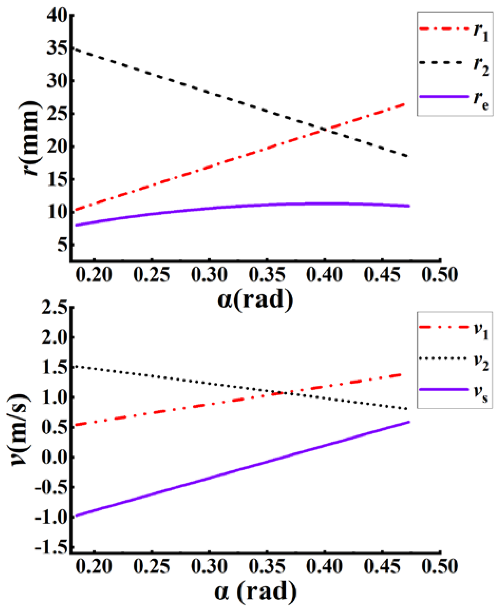
4.1. Gear Meshing Stiffness and Damping Analysis

With given parameters relevant to gear engagement, numerical solutions for mixed lubrication can be derived using a three-dimensional line contact mixed lubrication model. For a load of 50 N·m, a speed of 500 rpm, and a surface hardness of 2.38 GPa with surface roughness (represented by surface standard deviation σ) values of σ1 = 0.35644 μm, σ2 = 0.63991 μm, and σ3 = 0.92883 μm, the non-dimensional oil film thickness and pressure distribution from tooth engagement to disengagement were solved. Rough surfaces with micro-topography were generated through numerical simulation (as shown in Figure 2, and their roughness could be altered by adjusting control parameters. The three different roughness values presented in the text were obtained by calculating the statistical parameters (standard deviation) of the surface roughness.
As an example, the film thickness and pressure distribution across the pitch are shown in Figure 4, with the first and second rows corresponding to pressure and film thickness, respectively. It is evident that there are noticeable variations in film thickness across different surfaces. Given that both contact damping and contact stiffness are closely associated with film thickness, one can infer from Figure 4 that the meshing stiffness and damping of gears are affected by surface roughness at various engagement positions. Once the oil film thickness and distribution have been determined, meshing stiffness and damping can be obtained by substituting the film thickness h and the proportion of asperity contact λ into the appropriate formula.
In this study, the effects of different surface roughness on meshing stiffness and damping were analyzed and compared with the original stiffness Ksys without considering mixed lubrication. The values of speed, load, lubricant viscosity, and surface hardness were given as 500 rpm, 50 N·m, 0.096 Pa·s, and 2.38 GPa, respectively. Figure 5 shows the engagement stiffness and damping under different surface roughnesses. It can be seen from the figure that the greater the surface roughness, the smaller the damping and stiffness. As shown in Figure 5a, the overall amplitude of damping changes decreases with increasing surface roughness. When the engagement gear pair undergoes a sudden change in damping from double-tooth engagement to single-tooth engagement, the relative change amplitude increases with increasing surface roughness. Not only is the amplitude of damping changes greatly affected by the load, but the overall pattern of change in damping in the double-tooth engagement area is also different. According to Figure 5b, the higher the roughness, the smaller the stiffness, and there is almost no sudden change when the gear transitions from double-tooth engagement to single-tooth engagement. Additionally, it should be noted that when surface roughness and lubrication are not considered, i.e., the contact stiffness and damping are not included in the overall stiffness and damping of the gear, its damping is Csys, which is a constant value. Moreover, its stiffness, Ksys, is smaller than the stiffness of the rough tooth surface.

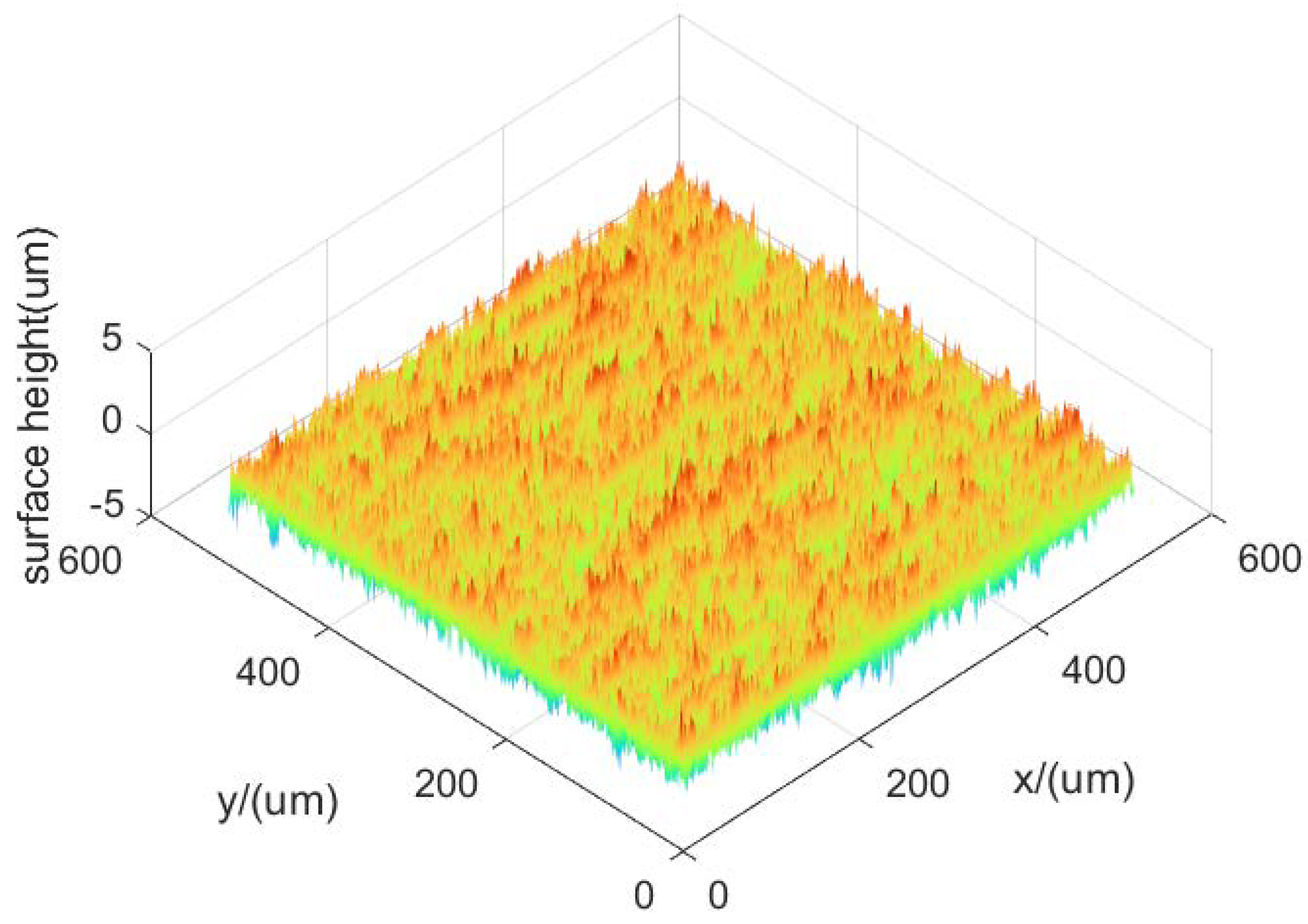
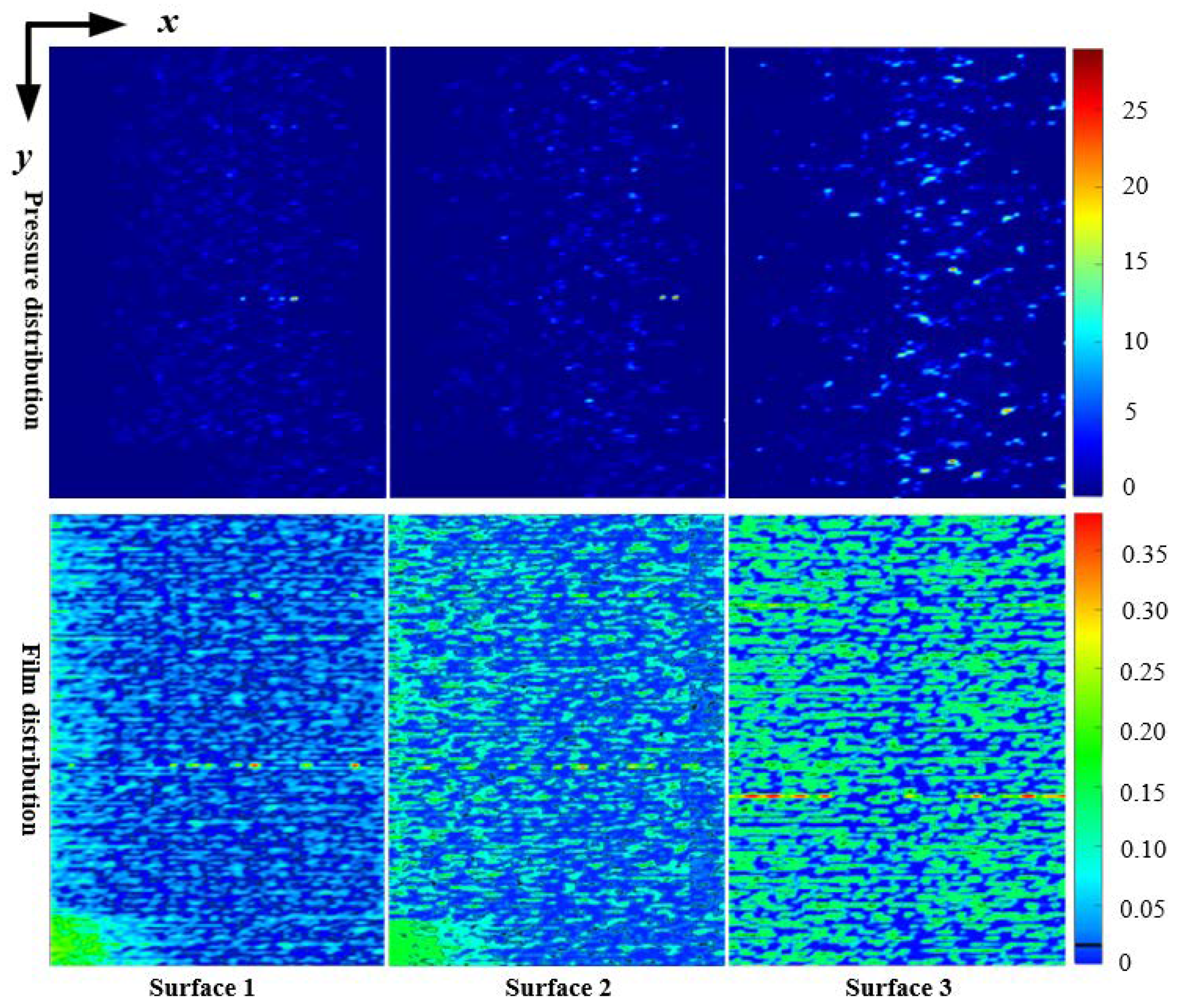
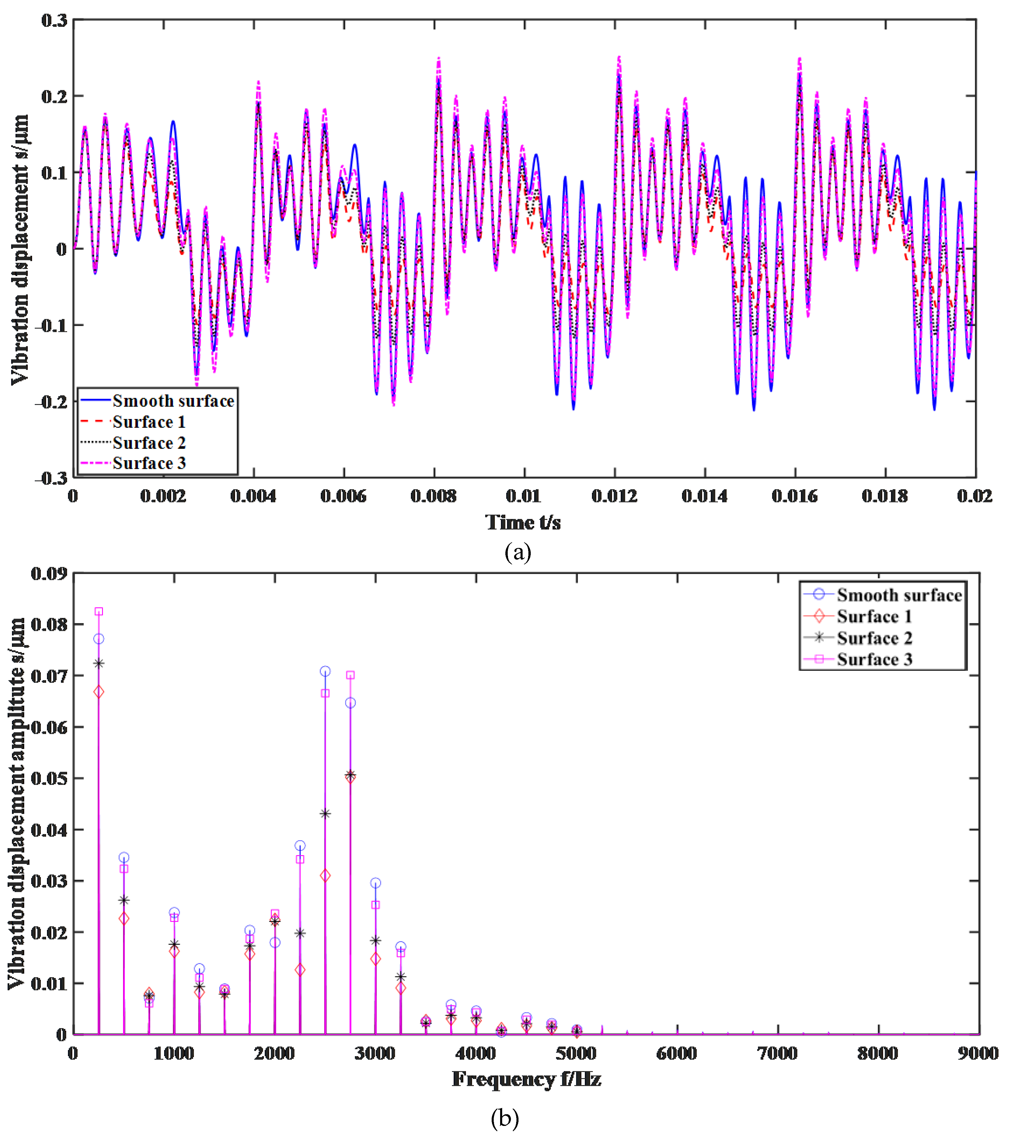
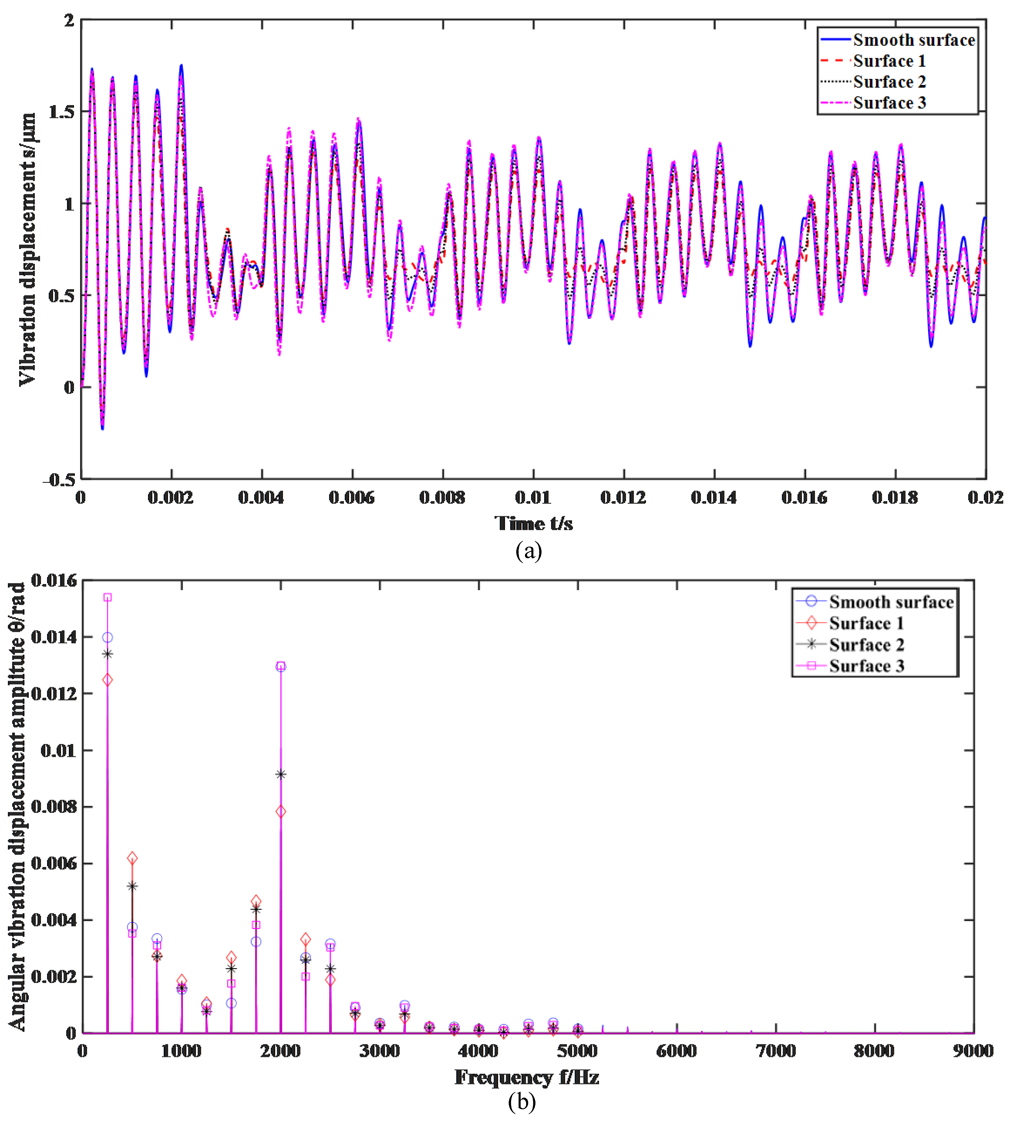
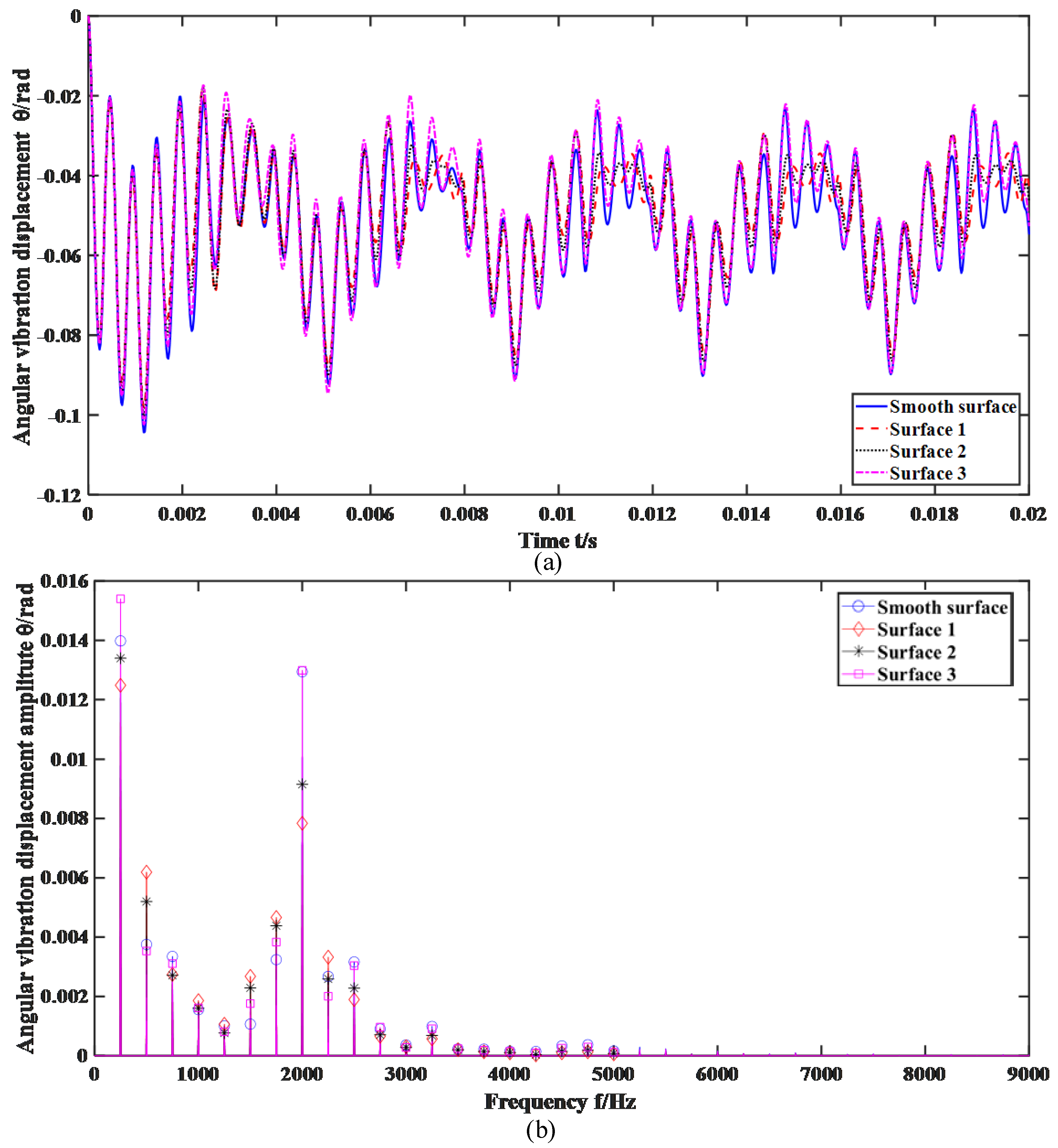
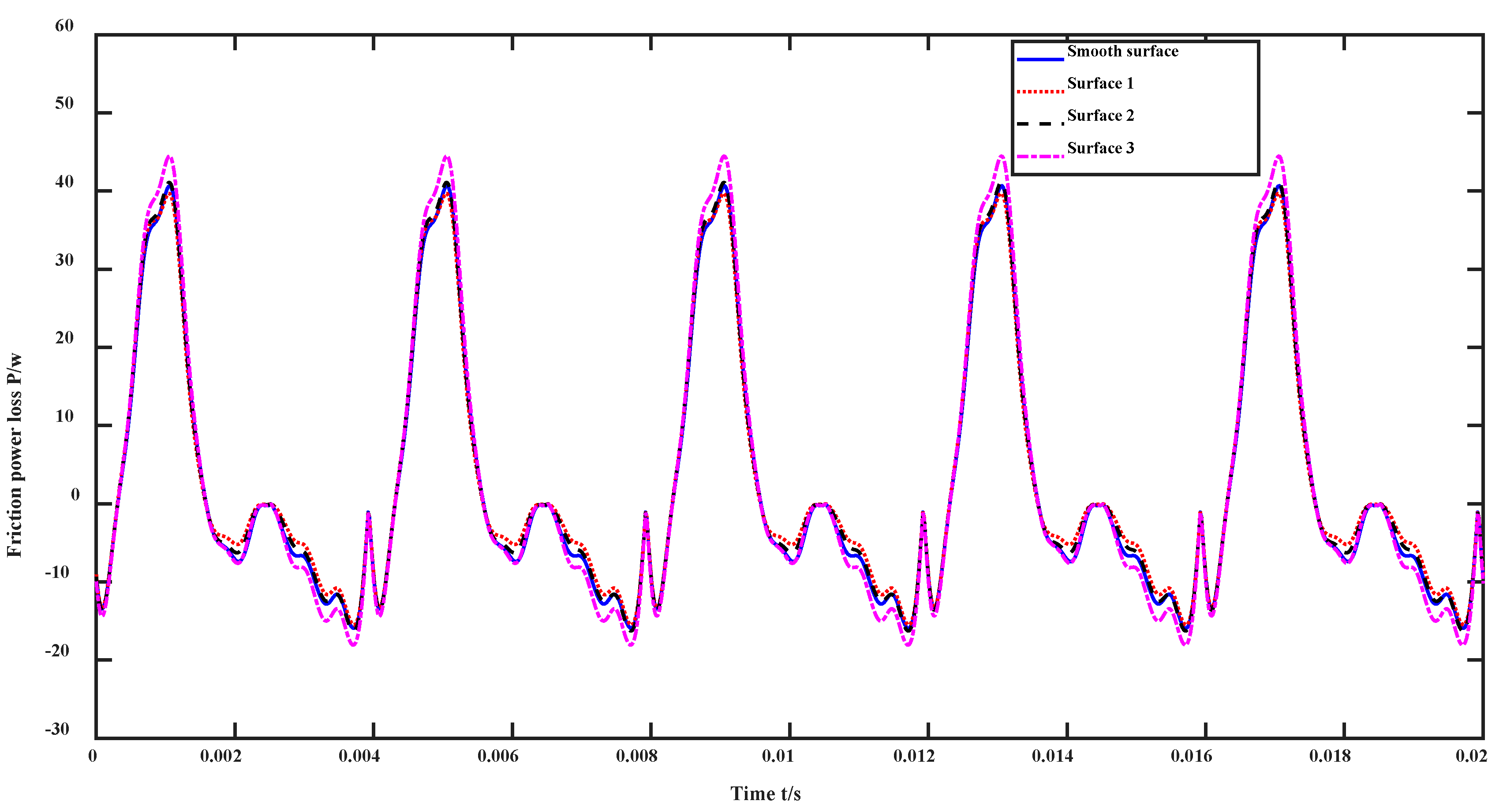
4.2. Dynamic Characteristics and Energy Loss Analysis

The dynamic characteristics and frictional energy dissipation of gears under mixed lubrication with different surface roughnesses are solved separately, and the results are compared with the dynamic response without considering lubrication and surface roughness. The main parameters used for the solution are listed in Table 1. The values of roughness 1, roughness 2, and roughness 3 are: σ1 = 0.35644 μm, σ2 = 0.63991 μm, and σ3 = 0.92883 μm.
The chart shown in Figure 6 displays the vibration displacement of the driven gear in the x-direction as well as its spectral plot. The maximum amplitude of the vibration displacement is around 0.25 μm, and except for the startup phase, a distinct periodical trend is observable in the variation in the vibration displacement after 0.008 s. The graph indicates a notable influence of varying surface roughness levels on vibration displacement, where despite similar trends over time, gears with higher roughness exhibit greater amplitude. It is worth noting that without considering surface roughness and mixed lubrication, the amplitude of vibration displacement for the smooth surface is significantly higher than those of gears with roughness σ1 and σ2 but more comparable to that of gears with roughness σ3. Furthermore, after the onset of steady, periodic variation in vibration displacement (post 0.008 s in the graph), the amplitude of the control group exceeds that of gears with roughness σ3 for about half of the duration.
From the spectrum chart, it is evident that the vibration displacement possesses distinct harmonic characteristics, manifesting as prominent peaks at the mesh frequency f, followed by its harmonics 11f and 12f. The amplitude is greatest at the mesh frequency f, followed by 11f and 12f, with spectral amplitudes becoming negligible beyond 5000 Hz. While the rules governing the spectral amplitude distribution remain consistent among surfaces with differing roughness levels, significant discrepancies exist among specific amplitudes at certain frequencies. At frequencies f, 8f, and 12f, gears with roughness level σ3 display the highest amplitudes. Except for frequency 3f, at all other harmonics, gears with smooth surfaces exhibit the greatest amplitudes. Moreover, apart from frequency 3f, the amplitude tends to increase with increasing roughness level.
The vibration displacement and spectrum chart of the driven gear in the y-direction are shown in Figure 7. It can be seen that during the start-up phase, the amplitude is relatively large, with values exceeding 1.5 μm. As the transmission stabilizes, the vibration displacement begins to exhibit periodic changes, with amplitudes not exceeding 1.5 μm. Similar to the x-directional vibration displacement, roughness has a greater impact on the change in vibration displacement, with larger changes observed as roughness increases. The smooth surface gear’s vibration displacement change amplitude is significantly higher than those of gears with roughness σ1 and σ2, but closer to that of gears with roughness σ3. However, there are slight differences in the temporal patterns of vibration displacement change, corresponding to different levels of roughness. Gears with smaller roughness exhibit local extrema at earlier times, with only the vibration displacement change pattern of gears with roughness σ3 being more consistent with the smooth surface gear. This indicates that roughness not only affects the amplitude of vibration displacement change but also influences its change pattern. Therefore, roughness has a greater impact on the y-directional vibration.
The frequency spectrum of the vibration displacement in the y-direction of the driven gear also exhibits distinct harmonic characteristics. However, unlike the x-direction, the maximum amplitude is at 8f, followed by the meshing frequency f. At multiple frequencies with significant amplitudes, larger roughness corresponds to larger amplitudes. It is worth noting that at 6f and 9f, smaller roughness results in larger spectral amplitudes. In the range of harmonics from 2f to 5f, the smooth surface gear has the largest spectral amplitudes. However, at 6f, the spectral amplitude of the smooth surface gear can be essentially ignored. By examining both the vibration displacement diagram and the distribution of the vibration displacement frequency spectrum, it can be seen that different levels of roughness have a greater impact on the y-directional vibration compared to the x-direction.θ.
Figure 8 shows the angular vibration displacement and frequency spectrum of the driven gear in the rotational direction. The larger the roughness, the greater the angular vibration amplitude. The smooth surface gear’s angular vibration amplitude change is significantly greater than that of gears with roughness σ1 and σ2. Although the smooth surface gear has a similar angular vibration amplitude to the gear with roughness σ3, there are time intervals where the amplitude is significantly greater than that of the gear with roughness σ3. In contrast to the y-directional vibration displacement, the smaller the roughness, the later the local extrema appear in the rotational angular vibration displacement.
The frequency spectrum distribution of rotational vibration displacement differs significantly from that of x- and y-directional displacements. While they both exhibit harmonic characteristics, the specific distribution of spectral amplitudes in the frequency domain varies greatly for gears with different roughness levels. The most notable difference is at several frequencies, such as 2f, 4f, 5f, 6f, 7f, and 9f, where smaller roughness corresponds to larger amplitude values. In some cases, the corresponding amplitude values are even greater than those of the smooth surface gear. Only at the meshing frequencies f, 8f, and 10f, gears with roughness σ3 have a significantly larger amplitude value compared to those with other roughness levels. Based on the analysis of rotational vibration displacement and its frequency spectrum, combined with the previous analysis of x- and y-directional vibrations, it can be concluded that roughness has the greatest impact on rotational vibration displacement.
It is worth noting that when surface roughness and mixed lubrication effects are not considered, the vibration of gears is significantly larger than when the surface roughness is small, while the gear vibration is close to that observed with larger surface roughness. This suggests it is essential to account for surface roughness and lubricating factors during nonlinear vibration analysis when gear manufacturing precision is high, i.e., when roughness is minimum.
The gear meshing force and its frequency spectrum are shown in Figure 9. It can be observed that under different conditions, the changes in the meshing force are highly consistent, with only minor differences in the specific values. The smooth surface gear has a smaller meshing force than that under consideration of roughness and lubrication, and the larger the roughness, the smaller the absolute peak value of the meshing force.
Compared to the vibration displacement frequency spectrum, the meshing force spectrum is complex, with the major amplitude distributed in the harmonics from f to 8f. Higher frequency ranges have negligible amplitudes, with each point decreasing successively as the frequency increases. At the meshing frequencies f and 2f, the amplitudes of the meshing force considering roughness and lubrication are greater than those of the smooth surface gear, and the amplitudes of the meshing force under various conditions are quite close at higher frequencies.
The energy loss due to frictional sliding during gear meshing is shown in Figure 10 (the negative sign indicates relative motion direction). As with the meshing force, the pattern of energy loss with time remains consistent under different conditions. The energy loss associated with gears under various roughness levels approaches similarity, except for specific time intervals within one cycle, where gears with roughness level σ3 have significantly greater energy losses than others, and gears with roughness level σ1 correspond to minimum energy loss.

5. Conclusions

This research is grounded in the analysis of mixed lubrication, with a focus on micro-interface contact. By incorporating friction, contact stiffness, and damping into the dynamic characteristics analysis of gear surfaces, we were able to establish a link between microscopic surface topography and gear performance. Building on this, we analyzed the vibration characteristics of gears under mixed lubrication conditions and calculated the energy loss caused by friction. The study concludes with several key findings:
(1).
Surface roughness has a direct impact on gear meshing stiffness and damping. As the roughness increases, both the contact stiffness and damping decrease;
(2).
Different surface roughness results in distinct vibration characteristics, with the overall trend being that the greater the roughness, the larger the amplitude of vibration. Although gears with different roughness have dissimilar frequency components, they all exhibit a clear harmonic characteristic. When the roughness is small, gear vibrations under rough surface conditions are less than those of smooth surface gear without considering roughness;
(3).
A higher surface roughness leads to increased mesh force, where the mesh force of the rough surface gear surpasses that of the smoother surface gear. The energy loss is similar to the vibration displacement under varying levels of roughness, i.e., increasing roughness means more significant energy loss. Yet interestingly, the energy loss in the smooth surface gear control group, which does not factor in roughness, outweighs that in cases of lower surface roughness;
(4).
While the gear tribo-dynamics model established in this study has connected surface micro-topography with gear dynamic characteristics, providing a theoretical basis for improving gear service performance, there are still some shortcomings. Firstly, the coupling relationship between tribology and dynamics is not tight enough, and parameter exchange has not been realized through real-time iteration. Secondly, the evolution of surface topography under actual conditions has not been sufficiently considered. Lastly, the analyzed working conditions and surface topographies are insufficient. In our subsequent research, we will mainly focus on addressing these three shortcomings.

Author Contributions

Validation, J.M.; Resources, J.L., K.S. and K.W.; Writing—original draft, G.C. and Y.W. All authors have read and agreed to the published version of the manuscript.

Funding

Supported by the National Key R&D Plan Project (Grant No. 2022YFB3404804), the Science and Technology Research Program of Chongqing Municipal Education Commission (Grant No. KJQN202303214) and Doctoral Science Foundation of Chongqing Industry Polytechnic College (2022GZYBSZK1-007).

Data Availability Statement

The datasets supporting the conclusions of this article are included within the article.

Conflicts of Interest

Author Yun Wang was employed by Shandong INVES Intelligent Equipment Co., Ltd. The remaining authors declare that the research was conducted in the absence of any commercial or financial relationships that could be construed as a potential conflict of interest.

Appendix A

Appendix A.1. Gear Parameters

The contact position relationship between involute gears in a gear pair is shown in Figure A1, where Point O denotes any engagement position on the tooth profile. Points O1 and O2, respectively, represent the centers of the pinion and wheel, while V1 and V2 denote the speeds of the small and large gears at point O. The common tangent of the base circle is denoted by K1K2, with rb1 and rb2 representing the radii of the base circles and α and β indicating the rolling angles. According to the principle of involute gears, the radius of curvature at contact point O can be expressed as follows:
r 1 = O K 1 = r b 1 tan α = O 1 K 1 tan α ,
r 2 = O K 2 = r b 2 tan β = O 2 K 2 tan β = K 1 K 2 O K 1 .
Figure A1. Gear meshing diagram.
Lubricants 12 00007 g0a1
The equivalent curvature radius at the engagement point is re = r1r2/(r1 + r2). Given the rotational speeds n1 and n2, the tangential velocity at the engagement point can be expressed according to the geometric relationship shown in Figure A1:
v 1 = r 1 ω 1 = r 1 π n 1 30 ,
v 2 = r 2 ω 2 = z 1 z 2 r 2 ω 1 = r 2 z 1 z 2 π n 1 30 .
The geometrical parameters of the wheel and pinion are listed in Table A1. Substituting these parameters into the expressions gives the curvature radius and speed during engagement, as shown in Figure A2, where vs denotes the relative sliding speed.
Table A1. Basic parameters of gears.
ParametersPinionWheel
Number of teeth3036
Module (mm)44
Pressure angle (°)2020
Radius of the base circle (mm)56.38267.658
Rotation speed (rpm)500416.667
Figure A2. Curvature radius r and speed v during the gear meshing process.
Lubricants 12 00007 g0a2
The total number of engaged gear teeth may exceed one, leading to load distribution across multiple pairs of teeth. With shifting engagement positions, the load placed upon individual engaged tooth pairs varies, necessitating an evaluation of load allocation among the various pairs. The load-sharing coefficients for these engaged tooth pairs are depicted in Figure A3. SAP is the start of the active profile, Tip donates the top point of gear, and LPSTC and HPSTC represent the lowest point and highest point of single-tooth contact, respectively.
Figure A3. The meshing force sharing coefficient of the gear pair. SAP: start of the active profile; Tip: top point of gear; LPSTC and HPSTC: lowest point and highest point of single-tooth contact.
Lubricants 12 00007 g0a3

Appendix A.2. Equation of Lubrication and Friction Analysis

Through the above analysis, we have obtained the variation in load, speed, and curvature radius during engagement. Involute straight gears belong to “linear-contact” components. In practical applications, the contact areas of “linear-contact” components tend to be rectangular rather than truly linear. The main control equations are:
x ρ 12 η h 3 p x + y ρ 12 η h 3 p y = u ( ρ h ) x + ( ρ h ) t .
In this context, u denotes the entrainment velocity, ρ refers to the density, η* indicates the viscosity, p represents the pressure, and h signifies the film thickness. When solving for the three-dimensional mixed EHL model, the equation for the film thickness should incorporate contact geometry, three-dimensional surface topography, and elastic deformation. As such, the equation for the film thickness is as follows:
h = h 0 ( t ) + f ( x , y , t ) + S 1 ( x , y , t ) + S 2 ( x , y , t ) + V ( x , y , t ) .
In this formula, the original roughness surfaces S1(x, y, t) and S2(x, y, t) have been determined, while the original gap h0(t) and contact geometry f(x, y, t) can be derived based on the geometric relationship of the contacting pair. The elastic deformation V(x, y, t) requires particular consideration in calculation as it is associated with pressure. Its calculation formula can be expressed as follows:
V ( x , y , t ) = 2 π E Ω p ( ξ , ζ ) ( x ξ ) 2 + ( y ζ ) 2 d ξ d ζ .
In the study, the lubricant is a non-Newtonian fluid, and the viscosity is:
1 η = 1 η τ 0 τ 1 Sinh ( τ 1 τ 0 ) .
In this context, τ0 and τ1, respectively, denote the shear stress under standard conditions and the ultimate shear stress, while η indicates the viscosity related to pressure, which can be derived through the following equation:
η = η 0 e α 0 p .
The density is given by:
ρ = ρ 0 ( 1 + 0.6 × 10 9 p 1 + 1.7 × 10 9 p ) .
A numerical solution necessitates convergence conditions. In this context, we utilize load balance to determine the attainment of convergence. As such, we have:
F ( t ) = Ω p ( x , y , t ) d x d y .
Through the above formula, we can determine the film thickness and pressure distribution. The friction coefficient is composed of two parts in a mixed lubrication state. In the hydrodynamic pressure region, the friction coefficient is determined by the shear stress of the lubricant that forms the elastic hydrodynamic oil film. In the asperity contact area, the friction coefficient is related to the materials. Over the entire solution domain, considering the friction coefficients in both cases, we can obtain the overall friction coefficient. In the hydrodynamic pressure region:
γ ˙ = τ ˙ G x τ L η ln ( 1 τ τ L ) ,
where τL and Gx are the limiting shear stress and limiting elastic modulus, respectively. Given τL and Gx, the shear stress can be obtained by solving Equation (A12), and then integrating the shear stress gives the friction coefficient. In the asperity contact area, the friction coefficient can be taken as a constant depending on the interface material, typically ranging from 0.08 to 0.15.

References

  1. Wang, K.L.; Cheng, H.S. A Numerical solution to the dynamic load, film thickness, and surface temperatures in spur gears, part I: Analysis. J. Mech. Des. 1981, 103, 177–187. [Google Scholar] [CrossRef]
  2. Hua, D.Y.; Khonsari, M. Application of transient elastohydrodynamic lubrication analysis for gear transmissions. Tribol. Trans. 1995, 38, 905–913. [Google Scholar] [CrossRef]
  3. Shi, S.; Li, J.; Wu, L. An investigation of the lubrication regime in slow speed gearing under heavy loads. J. Southwest Jiaotong Univ. 1987, 1, 91–101. (In Chinese) [Google Scholar]
  4. Zhang, Y.; Mei, X. Study on the unsteady state effect of elastic-hydrodynamic lubrication in spur gear meshing. J. Mech. Eng. 2000, 36, 32–35. (In Chinese) [Google Scholar] [CrossRef]
  5. Yi, X.; Wang, Y. Analysis of the isothermal transient Non-Newtonian EHL of the involute spur gear. Lubr. Eng. 2004, 3, 54–56. (In Chinese) [Google Scholar]
  6. Chang, X.; Renqing, D.; Liao, L.; Zhu, P.; Lin, B.; Huang, Y.; Luo, S. Study on hydrodynamic lubrication and friction reduction performance of spur gear with groove texture. Tribol. Int. 2023, 177, 107978. [Google Scholar] [CrossRef]
  7. Lu, R.; Tang, W.; Huang, Q.; Xie, J. An Improved Load Distribution Model for Gear Transmission in Thermal Elastohydrodynamic Lubrication. Lubricants 2023, 11, 177. [Google Scholar] [CrossRef]
  8. Farrenkopf, F.; Schwarz, A.; Lohner, T.; Stahl, K. Analysis of a Low-Loss Gear Geometry Using a Thermal Elastohydrodynamic Simulation including Mixed Lubrication. Lubricants 2022, 10, 200. [Google Scholar] [CrossRef]
  9. Hirani, H.; Jangra, D.; Sidh, K.N. Experimental Analysis of Chemically Degraded Lubricant’s Impact on Spur Gear Wear. Lubricants 2023, 11, 201. [Google Scholar] [CrossRef]
  10. Hirani, H.; Jangra, D.; Sidh, K.N. Experimental Investigation on the Wear Performance of Nano-Additives on Degraded Gear Lubricant. Lubricants 2023, 11, 51. [Google Scholar] [CrossRef]
  11. Sivayogan, G.; Rahmani, R.; Rahnejat, H. Transient non-Newtonian elastohydrodynamics of rough meshing hypoid gear teeth subjected to complex contact kinematics. Tribol. Int. 2022, 167, 107398. [Google Scholar] [CrossRef]
  12. Wang, Y.; Li, H.; Tong, J.; Yang, P. Transient thermo-elastohydrodynamic lubrication analysis of an involute spur gear. Tribol. Int. 2004, 37, 773–782. [Google Scholar] [CrossRef]
  13. Lu, L.; Cai, Y. Transient Non-Newtonian elastohydrodynamic lubrication of spur gear transmission. Lubr. Eng. 2005, 6, 36–38. (In Chinese) [Google Scholar]
  14. Guilbault, R.; Lalonde, S.; Thomas, M. Nonlinear damping calculation in cylindrical gear dynamic modeling. J. Sound Vib. 2012, 33, 2110–2128. [Google Scholar] [CrossRef]
  15. Zhang, Y.; Liu, H.; Zhu, C.; Liu, M.; Song, C. Oil film stiffness and damping in an elastohydrodynamic lubrication line contact-vibration. J. Mech. Sci. Technol. 2016, 30, 3031–3039. [Google Scholar] [CrossRef]
  16. Zhou, C.; Xiao, Z.; Chen, S.; Han, X. Normal and tangential oil film stiffness of modified spur gear with non-Newtonian elastohydrodynamic lubrication. Tribol. Int. 2017, 109, 319–327. [Google Scholar] [CrossRef]
  17. Zhou, C.J.; Xiao, Z.L. Stiffness and damping models for the oil film in line contact elastohydrodynamic lubrication and applications in the gear drive. Appl. Math. Model. 2018, 61, 634–649. [Google Scholar] [CrossRef]
  18. Xiao, Z.L. Oil Film Stiffness Model and Parameter Analysis for Modified Spur Gears Based on Elastohydrodynamic Lubrication. Ph.D. Thesis, Hunan University, Changsha, China, 2017. [Google Scholar]
  19. Castro, J.; Campos, A.; Sottomayor, A.; Seabra, J. Friction coefficient between gear teeth in mixed film lubrication. In Tribology and Interface Engineering Series; Elsevier: Amsterdam, The Netherlands, 2005; Volume 48, pp. 525–533. [Google Scholar]
  20. Ouyang, T.; Cheng, N.; Niu, Y. Mixed elastohydrodynamic lubrication for involute gear with different rough surfaces. J. Jilin Univ. (Eng. Technol. Ed.) 2016, 46, 1933–1939. (In Chinese) [Google Scholar]
  21. Li, S.; Kahraman, A. A transient mixed elastohydrodynamic lubrication model for spur gear pairs. J. Tribol. 2010, 132, 011501. [Google Scholar] [CrossRef]
  22. Chimanpure, A.S.; Kahraman, A.; Talbot, D. A transient mixed elastohydrodynamic lubrication model for helical gear contacts. J. Tribol. 2021, 143, 061601. [Google Scholar] [CrossRef]
  23. Cheng, G.; Xiao, K.; Wang, J.; Pu, W.; Han, Y. Calculation of gear meshing stiffness considering lubrication. J. Tribol. 2020, 142, 031602. [Google Scholar] [CrossRef]
  24. Cheng, G.; Xiao, K.; Wang, J. Contact damping and stiffness calculation model for rough surface considering lubrication in involute spur gear. Int. J. Appl. Mech. 2021, 13, 2150078. [Google Scholar] [CrossRef]
  25. Wang, Z.; Pu, W.; Pei, X.; Cao, W. Contact stiffness and damping of spiral bevel gears under transient mixed lubrication conditions. Friction 2022, 10, 545–559. [Google Scholar] [CrossRef]
  26. Li, S. A thermal tribo-dynamic mechanical power loss model for spur gear pairs. Tribol. Int. 2015, 88, 170–178. [Google Scholar] [CrossRef]
  27. Li, S.; Anisetti, A. A tribo-dynamic contact fatigue model for spur gear pairs. Int. J. Fatigue 2017, 98, 81–91. [Google Scholar] [CrossRef]
  28. Ankouni, M.; Lubrecht, A.; Velex, P. Modelling of damping in lubricated line contacts—Applications to spur gear dynamic simulations. Proc. Inst. Mech. Eng. Part C J. Mech. Eng. Sci. 2016, 230, 1222–1232. [Google Scholar] [CrossRef]
  29. Xiao, Z.; Zhou, C.; Chen, S.; Li, Z. Effects of oil film stiffness and damping on spur gear dynamics. Nonlinear Dyn. 2019, 96, 145–159. [Google Scholar] [CrossRef]
  30. Cao, W.; Pu, W.; Wang, J. Tribo-dynamic model and fatigue life analysis of spiral bevel gears. Eur. J. Mech. A Solid 2019, 74, 124–138. [Google Scholar] [CrossRef]
  31. Cao, W.; He, T.; Pu, W.; Ke, X. Dynamics of lubricated spiral bevel gears under different contact paths. Friction 2022, 10, 247–267. [Google Scholar] [CrossRef]
  32. Huang, S.W. The Influence of Micro Surface Topography on Gear Dynamic Parameters and Dynamic Characteristics. Master’s thesis, Hefei University of Technology, Hefei, China, 2016. [Google Scholar]
  33. Li, Z.; Wang, J.; Zhang, H.; Chen, J.; Liu, K. Influence of surface topography on the friction and dynamic characteristics of spur gears. Proc. Inst. Mech. Eng. Part J J. Eng. Tribol. 2020, 234, 1892–1907. [Google Scholar] [CrossRef]
  34. Xiang, G.; Yang, T.; Guo, J.; Wang, J. Optimization transient wear and contact performances of water-lubricated bearings under fluid-solid-thermal coupling condition using profile modification. Wear 2022, 502–503, 204379. [Google Scholar] [CrossRef]
  35. Tang, D.; Xiang, G.; Guo, J.; Cai, J.; Yang, T.; Wang, J.; Han, Y. On the optimal design of staved water-lubricated bearings driven by tribo-dynamic mechanism. Phys. Fluids 2023, 35, 093611. [Google Scholar] [CrossRef]
  36. Guo, J.; Ding, B.; Wang, Y.; Han, Y. Co-optimization for hydrodynamic lubrication and leakage of V-shape textured bearings via linear weighting summation. Phys. Scr. 2023, 98, 125218. [Google Scholar] [CrossRef]
  37. Gupta, N.; Tandon, N.; Pandey, R.K.; Vidyasagar, K.C.; Kalyanasundaram, D. Tribodynamic studies of textured gearsets lubricated with fresh and MoS2 blended greases. Tribol. Int. 2022, 165, 107247. [Google Scholar] [CrossRef]
  38. Jiang, Y.; Chen, Z.; Tong, S.; Li, S.; Tong, Z. Gear tribodynamic modeling and analysis considering tooth profile modification. Tribol. Int. 2023, 178, 108023. [Google Scholar] [CrossRef]
  39. Chen, Z.; Jiang, Y.; Li, S.; Tong, Z.; Tong, S.; Tang, N. Uncertainty propagation of correlated lubricant properties in gear tribodynamic system. Tribol. Int. 2023, 179, 107812. [Google Scholar] [CrossRef]
  40. Li, Z.; Zhu, C.; Liu, H.; Gu, Z. Mesh stiffness and nonlinear dynamic response of a spur gear pair considering tribo-dynamic effect. Mech. Mach. Theory 2020, 153, 103989. [Google Scholar] [CrossRef]
  41. Mughal, H.; Dolatabadi, N.; Rahmani, R. An integrated tribodynamic model for investigation of efficiency, durability and NVH attributes of gear mesh in electric vehicle powertrains. Tribol. Int. 2023, 189, 108977. [Google Scholar] [CrossRef]
  42. Jiang, Y.; Tong, S.; Tong, Z.; Li, S.; Cheng, W. Tribodynamic analysis of spur gear drives with uncertain time-variant loads: An interval process approach. Mech. Mach. Theory 2024, 191, 105511. [Google Scholar] [CrossRef]
  43. Huangfu, Y.; Dong, X.; Chen, K.; Tu, G.; Long, X.; Peng, Z. A tribo-dynamic based pitting evolution model of planetary gear sets: A topographical updating approach. Int. J. Mech. Sci. 2022, 220, 107157. [Google Scholar] [CrossRef]
  44. Chen, Z.; Jiang, Y.; Li, S.; Tong, Z.; Tong, S.; Tang, N. Effect of lubricant viscosity on dynamics of high-precision gear considering lubricant-induced backlash reduction. Tribol. Int. 2022, 168, 107447. [Google Scholar] [CrossRef]
  45. Sánchez, M.B.; Pleguezuelos, M.; Pedrero, J.I. Approximate equations for the meshing stiffness and the load sharing ratio of spur gears including hertzian effects. Mech. Mach. Theory 2017, 109, 231–249. [Google Scholar] [CrossRef]
  46. Ren, N.; Zhu, D.; Chen, W.W.; Liu, Y.; Wang, Q.J. A three-dimensional deterministic model for rough surface line-contact EHL problems. J. Tribol. 2009, 131, 011501. [Google Scholar] [CrossRef]
  47. Yang, D.C.H.; Lin, J.Y. Hertzian damping, tooth friction and bending elasticity in gear impact dynamics. J. Mech. Trans. Autom. Des. 1987, 109, 189–196. [Google Scholar] [CrossRef]
  48. Sainsot, P.; Velex, P.; Duverger, O. Contribution of gear body to tooth deflections-a new bi-dimensional analytical formula. J. Mech. Des. 2004, 126, 748–752. [Google Scholar] [CrossRef]
  49. Bakolas, V. Numerical generation of arbitrarily oriented non-Gaussian three dimensional rough surfaces. Wear 2003, 254, 546–554. [Google Scholar] [CrossRef]
  50. Smith, J.D. Gear Noise and Vibration; Marcel Dekker: New York, NY, USA, 2003; pp. 27–76. [Google Scholar]
Figure 1. Force analysis diagram of a single-tooth. F: meshing force; a: pressure angle; d: distance from acting point to root circle; and hx: tooth thickness.
Lubricants 12 00007 g001
Figure 2. The micro−topography of the tooth surface.
Lubricants 12 00007 g002
Figure 3. Illustration of the gear dynamics model.
Lubricants 12 00007 g003
Figure 4. The distribution of pressure and film thickness at the pitches of different tooth surfaces.
Lubricants 12 00007 g004
Figure 5. Damping (a) and stiffness (b) of different rough surfaces: σ1 = 0.35644 μm, σ2 = 0.63991 μm, and σ3 = 0.92883 μm. Csys and Ksys: damping and stiffness without considering roughness and lubrication.
Lubricants 12 00007 g005
Figure 6. Vibration displacement in the x-direction (a) and its frequency spectrum (b) on different rough surfaces.
Lubricants 12 00007 g006
Figure 7. Vibration displacement in the y-direction (a) and its frequency spectrum (b) on different rough surfaces.
Lubricants 12 00007 g007
Figure 8. Vibration displacement in rotation-direction (a) and its frequency spectrum (b) for different rough surfaces.
Lubricants 12 00007 g008
Figure 9. Meshing force (a) and its spectrum (b).
Lubricants 12 00007 g009
Figure 10. Energy loss caused by tooth surface friction.
Lubricants 12 00007 g010
Table 1. Parameters used in the calculation.
ParametersPinionWheel
Number of teeth3036
Module (mm)44
Pressure angle (°)20
Load (N·m)50
Rotation speed (rpm)500416.667
Mass (kg)1.5822.3566
Moment of inertia (kg·m2)0.0017530.003536
Bearing
stiffness (N/m)/damping (N·s/m)
6.9127 × 10⁸/1804
Torsional stiffness (N/m)/damping (N·s/m)7.6712 × 108/2209
Disclaimer/Publisher’s Note: The statements, opinions and data contained in all publications are solely those of the individual author(s) and contributor(s) and not of MDPI and/or the editor(s). MDPI and/or the editor(s) disclaim responsibility for any injury to people or property resulting from any ideas, methods, instructions or products referred to in the content.

