Article

Experimental Investigation on the Effect of Velocity Anisotropy on Oil Film State under Different Surface Wettability Interface

School of Mechanical & Automotive Engineering, Qingdao University of Technology, 777 Jialingjian Road, Qingdao 266520, China
*
Author to whom correspondence should be addressed.
Lubricants 2023, 11(9), 381; https://doi.org/10.3390/lubricants11090381
Submission received: 8 August 2023 / Revised: 28 August 2023 / Accepted: 5 September 2023 / Published: 7 September 2023
(This article belongs to the Special Issue Friction and Wear of Rolling-Element Bearings)

Abstract

:
This study focuses on the utilization of surface modification technology to create glass disks with varying surface wettability. A measurement test bench for point contact lubrication film is employed to investigate the impact of changes in the angle between the velocities of the glass disk and steel ball on the state of the lubricating oil film at the interface. The results show that altering the surface wettability reduces the adhesive strength between the interface and the adjacent lubricant, leading to a decrease in the ultimate shear stress, and inducing interface slippage. When the rotational velocity of the disk matches the translational velocity of the ball and their trajectories are inclined at specific angles, the sliding velocity increases proportionally to the inclination angle, which contributes significantly to the thermal effect. Furthermore, when the velocity varies across the interface with differences in wettability, the contact zone forms a wedge-shaped gap and causes modifications in the oil film’s shape, including the formation of an inlet dimple and an inclined straight stripe. The dominant factor influencing the interface is the slip when the angle is acute, whereas the thermal effect plays a significant role when the angle is obtuse. This work is expected to provide a new strategy for elastohydrodynamic lubrication under surface wettability interfaces.

1. Introduction

In order to meet the demands of complex and fine transmission components, higher levels of lubricity are required, as driven by advancements in science and technology. In the application of elastic fluid lubrication, many gears and bearing parts with multiple pairs are under the harsh working conditions of high speed and heavy load. It is necessary to study the surface lubrication’s condition by observing the surface oil film’s shape and center thickness. Classical elastohydrodynamic lubrication (EHL) has the characteristics of a flat contact area, film thickness shrinkage at the outlet, a secondary pressure peak, horseshoe shape, etc., which are widely recognized by scholars. However, under some special conditions, these characteristics of the oil film will disappear, and the oil film will show abnormal behavior instead. Sibley and Chiu [1] used polyisobutylene as a lubricant in 1972, and experimentally discovered for the first time that the oil film formed a “dimple” in the central contact area. The occurrence of the oil film “dimple” indicates that there is an elastic deformation, which can easily cause parts failure, so people have begun to conduct in-depth research on the phenomenon of the “dimple”. Kaneta [2] found that when the steel ball was sliding purely, the oil film morphology was consistent with the typical elastic-flow oil film, and he explained that this was due to the difference in the elastic modulus leading to a normal extrusion. Ehret et al. [3] successfully explained the formation of the dimple under the pure sliding of the glass disk with plug flow. However, in the numerical simulation, the dimple of the oil film disappeared during the pure sliding of the steel ball, which was not consistent with the experiment. In 2000, Qu, Yang [4,5] et al., based on the “viscosity wedge” mechanism proposed by Cameron [6], studied the pure sliding conditions of the steel ball and glass disk, obtained a complete numerical solution of the steady-state linear contact thermoelastic hydrodynamic lubrication (TEHL) problem, and explained the Kaneta dimple phenomenon with the “temperature viscosity wedge”. At the same time, the sliding velocity effect along the entrainment velocity direction has also been studied. The sliding speed causes shear heating at the inlet, causing the heat generated from the contact to be transferred to the inlet area and resulting in a decrease in inlet viscosity. Based on this assumption, many scholars have proposed a lot of oil film thickness correction formulas [7,8,9].
In recent years, some scholars have begun to pay attention to experimental studies in the direction of different sliding speeds and winding speeds. Omasta et al. [10], in a point contact experiment formed of a glass disk and a steel ball, studied the influence of different angles between the slip ratio, the suction speed, and the sliding speed on the film’s thickness. The results show that the oil film morphology is asymmetric with the change in the surface velocity’s direction, and this asymmetry increases with the increase in the angle of the surface velocity’s direction. He further believed that the sliding direction would affect the shape of the lubricating film, but at low sliding speeds this effect was negligible [11,12].
In gear transmission and worm gear transmission, when the sliding speed is high, the oil film in the contact zone will change significantly, and the thickness of the oil film will increase locally, resulting in the so-called “dimple” phenomenon. Many researchers have proposed a number of models [13,14,15,16] to explain the emergence of the “dimple” phenomenon. However, the research community has not reached a unified conclusion on the question of whether thermal effects, velocity effects, interface slip effects, or other unknown factors play a dominant role in the “dimple” phenomenon. It is worth noting that the interface slip plays a crucial role in the formation of the “dimple” phenomenon when the speed is low, the thermal effect caused by the sliding speed is weak, and the interface slip effect has become the main factor affecting the abnormal behavior of the oil film.
At the microscopic scale, the influence of the interface slip on the state of the lubricant cannot be ignored, and many scholars have explored its mechanism and characteristics through theories and experiments. Within the literature, Black [17] proposed that the slip is related to the surface energy (contact angle). When a solid surface is completely wetted, the liquid exhibits a strong adhesion, resulting in the formation of a no-slip plane within the liquid. The distance between this no-slip plane and the solid interface does not exceed the diameter of a single molecule. Vinogradova [18] analyzed the “appearance” slip of fluids at the hydrophobic interface and concluded that this slippage was caused both by a less viscous oil film close to the solid interface and, possibly, by an air film at the solid/liquid interface. Xiang [19] proposed a surface profile modification method to improve the transient wear and bending contact performance of water-lubricated bearings under fluid–solid–thermal coupling. Tretheway [20] analyzed the absence of slippage at hydrophilic interfaces. At hydrophobic interfaces, the slip velocity is close to 10% of the free stream velocity and the slip length is approximately 1 μm, indicating that slip effects cannot be ignored at the micro/nanoscale. Choo [21] discovered a decrease in the friction coefficient in hydrophobic/hydrophilic contacts, with slips occurring at hydrophobic interfaces. At present, the processing of surface wettability has become an important method for the improvement of tribological performance parts. Some researchers use different methods to prepare the coated surface, for example, reactive magnetron sputtering for coating surfaces [22], the nanosecond laser ablation preparation of 40Cr steel hydrophobic sinusoidal-textured surfaces [23], AlN/CrN coating [24], the design and preparation of sic thin films, and the subsequent chemical grafting modification devices using new reactive sintering methods [25]. The experiments show that the increase in the surface hydrophobicity is beneficial for the decrease in the friction coefficient. Under differences in surface wettability, the research of the elastohydrodynamic lubrication films of hydrodynamic lubrication provides a new strategy. Lu Hewei [26] conducted an experimental observation on the morphology of the depleted oil boundary and the elastic flow lubricating film under the surface tension-driven and velocity cross-co-operative backfilling mechanism, with differences in wettability at the limited oil supply interface. When the surface velocities are in different directions, the lateral backfilling of the lubricant [27,28] caused by the speed track crossing of the two contact sub-surfaces has a great influence on the lubrication state of the oil film, and parameters such as speed, speed angle, and load have a great influence on the appearance of an abnormal oil film. Therefore, by using the point-contact surface-velocity anisotropic light-interference lubricating oil film measurement device, through the observation of the elastic fluid lubrication contact area under differences in wettability, the oil pool shape, central film thickness, and other parameters of elastic fluid lubrication under differences in wettability are obtained, so as to reveal the abnormal lubrication characteristics of elastic fluid lubrication under different working conditions, explore the mechanisms of thermal effect and interface slip on the lubrication behavior of elastic fluid, and provide a theoretical basis for the study of elastic fluid lubrication.

2. Materials and Methods
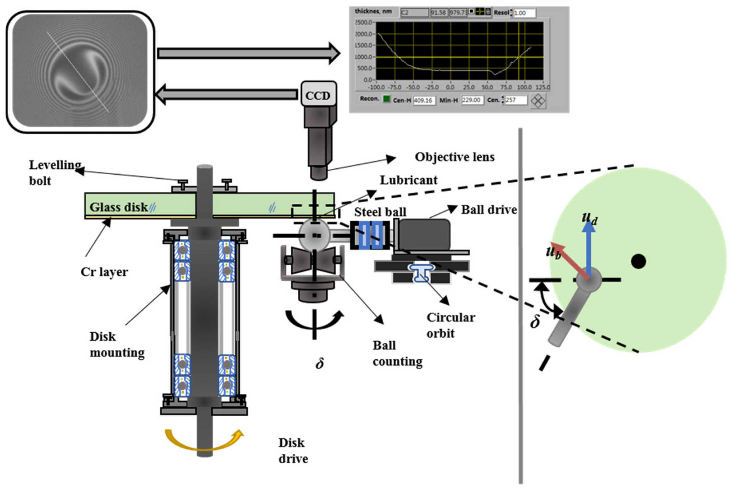
2.1. Test Device

This experiment was conducted on a self-developed point contact surface velocity anisotropic optical elastohydrodynamic lubrication film measurement test rig in a laboratory [29]. The experimental setup is shown in Figure 1 and it utilizes monochromatic light interference measurement technology. By analyzing the bright and dark interference fringes formed by the superposition of coherent light in the contact area, combined with the MBI film thickness processing software [30,31] the lubricating oil film’s thickness at the corresponding position could be calculated. The measurement accuracy could reach 0.89 nm. The motors on the glass disc and servo motor simulated their high sub-point contact, and the glass disc and steel ball were driven by two independent servo motors with reducers. The ball drive system was connected to the HepcoMotion arc guide and could adjust the angle δ of the surface velocity of the ball and disc to achieve its surface velocity association. The motor base was mounted on the circular guide rail, and the ball drive system was reversed to achieve a continuous change in the angle of the ball and disc speed in the range of 0°–180°.

2.2. Experimental Model

In this paper, the anomalous characteristics of lubricating oil film under differences in wettability are consistent with the different disc and ball speeds; that is, that the suction velocity and sliding velocity are orthogonal. At this point, the surface velocity can be equivalent to the velocity vector model shown in Figure 2.
Because the linear velocity direction of the glass disk is constant, when the motor base is in different positions on the arc guide rail, different speed angles are formed between the linear velocity (ub) direction of the steel ball and the linear velocity (ud) direction of the glass disc when the motor base is in different positions (δ). ue represents the suction speed and the us represents the sliding speed, the expression of which can be referred to in [32].

2.3. Experimental Protocol

The experimental ambient temperature was 22 ± 1 °C and the load range was 10–40 N. In this experiment, a K9 glass disk with a diameter of 150 mm and a thickness of 15 mm was used, and the working surface was coated with 1 layer of chromium film and 1 layer of silica film, and its surface roughness was about 8 nm. The diameter of the steel ball was 25.4 mm, its accuracy was G5 grade, and the surface roughness was about 5 nm. The range of the ball speed and disc speed was 0.01–12.8 mm/s. The PB1300 used in the experiment is a class of polymers, which are prone to interface slip, and its physical properties are shown in Table 1.
The use of AF solution to modify the glass disk in the process of surface modification refers to the existing literature [26], in which authors have elaborated that as the modified glass disk surface wettability changes, its oleo-phobic hydrophobicity increases and the adhesion of the lubricant to its surface decreases, and its modified interface is referred to as the AF interface.
When comparing the orthogonal suction speed and sliding speed, and the effect of the speed, speed angle, and load on the elastomeric lubricating oil film, the speed angle (δ) = 15°, 30°, 45°, 60°, 120°, 135°, 150°, 165°; the disc speed is equal to ball speed (ub = ud) = 0.1, 0.2, 0.4, 0.8, 1.6, 3.2, 6.4, 12.8 mm/s; the load is 10 N, 20 N, 30 N, 40 N; and PB1300 lubricant is used.

3. Results and Discussion

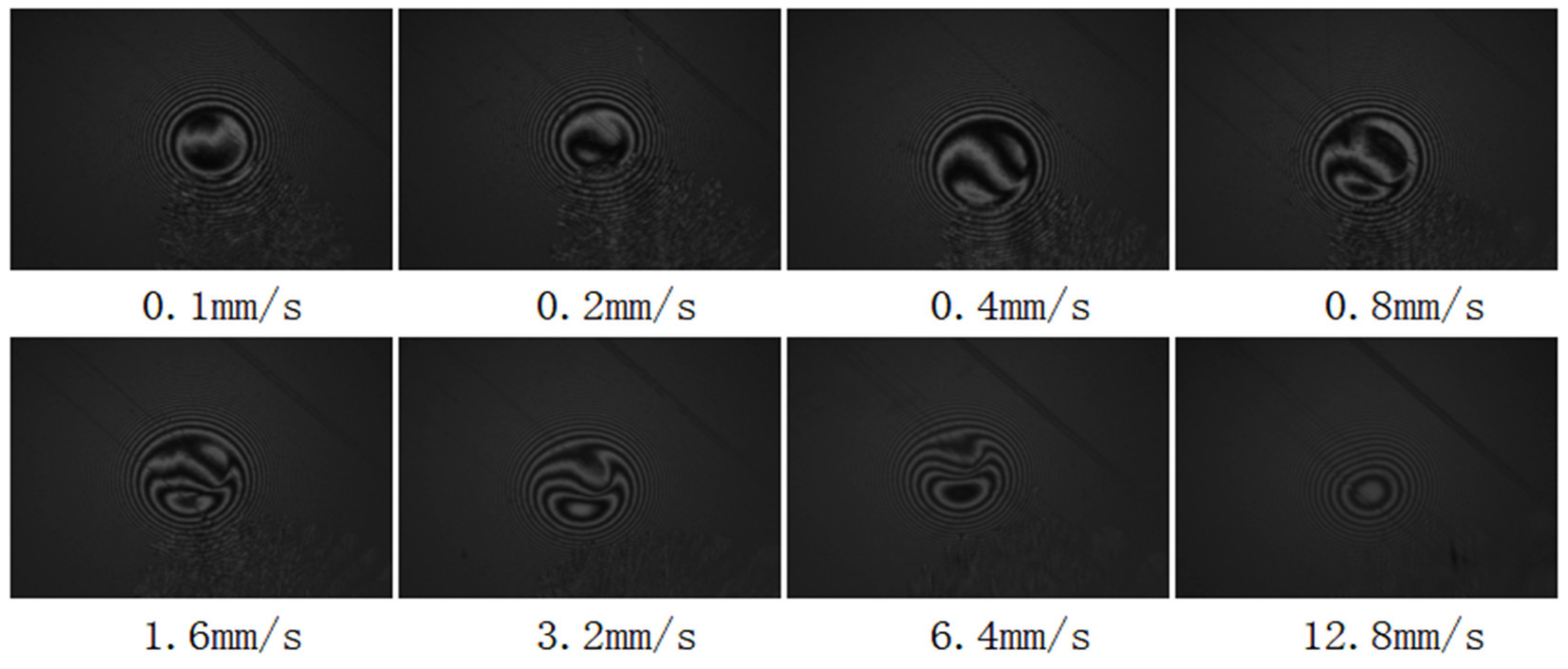
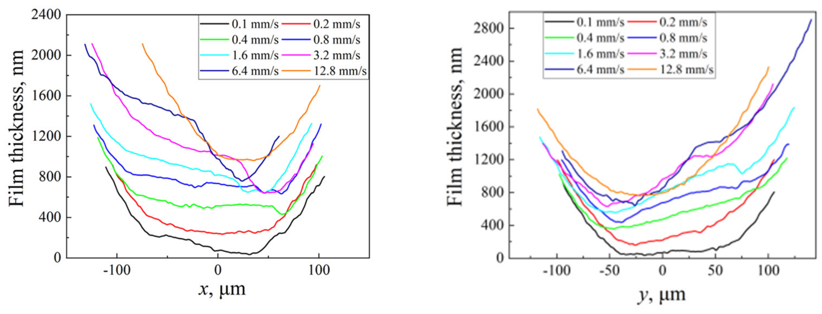
3.1. Effect of Velocity Change on Oil Film State

3.1.1. Surface Velocity Angle (0–90°)

Figure 3 and Figure 4 show the film thickness curve and optical interference image of PB1300 with different velocities on the morphology of the lubricating oil film under the condition of a 45° AF surface velocity angle. It is found from the figure that when the load is 20 N and the speed is 0.1 mm/s, a half-moon shape appears in the x direction along the direction of the winding speed, and with a further increase in speed, the overall film thickness curve increases, but its front half-moon gradually shrinks until it disappears. At the same time, however, the increase in the slope of the film thickness curve becomes flattened, which indicates that the wedge gap in the contact zone increases without the pure slip of PB1300 [32] at the AF interface. At a load of 20 N, the minimum thickness is almost unchanged, but when the surface velocity direction is different, the inhibitory effect of high loads on the minimum thickness is weakened.
Along the y direction of the sliding speed, with the increase in speed, the thickness of the oil film gradually increases, more lubricants are involved in the contact zone, and the overall film thickness also increases; in addition, when the speed increases, the shape of the thick oil film appears asymmetrical, although its essence at this speed is of an extremely low state, and the thermal effect has little effect. Therefore, the interface slip is the main factor due to the difference in the interface properties of the contact surface, as the lubricant has a velocity discontinuity at the limit of the shear stress close to the surface, resulting in an abnormal film thickness increase in the oil film thickness curve. At a speed of 0.4 mm/s, a half-crescent dimple occurs, which corresponds to the entrance half-moon dimple in the optical interferogram. With the further increase in speed, the overall film thickness curve increases and the film thickness curve generally shows an upward trend, but the bulge at the front end of the film thickness curve gradually decreases, and the bulge on the film thickness curve completely disappears when the speed reaches 12.8 mm/s. But at the same time, the slope of the film thickness curve gradually increases, which means that the wedge gap in its contact zone also gradually increases.

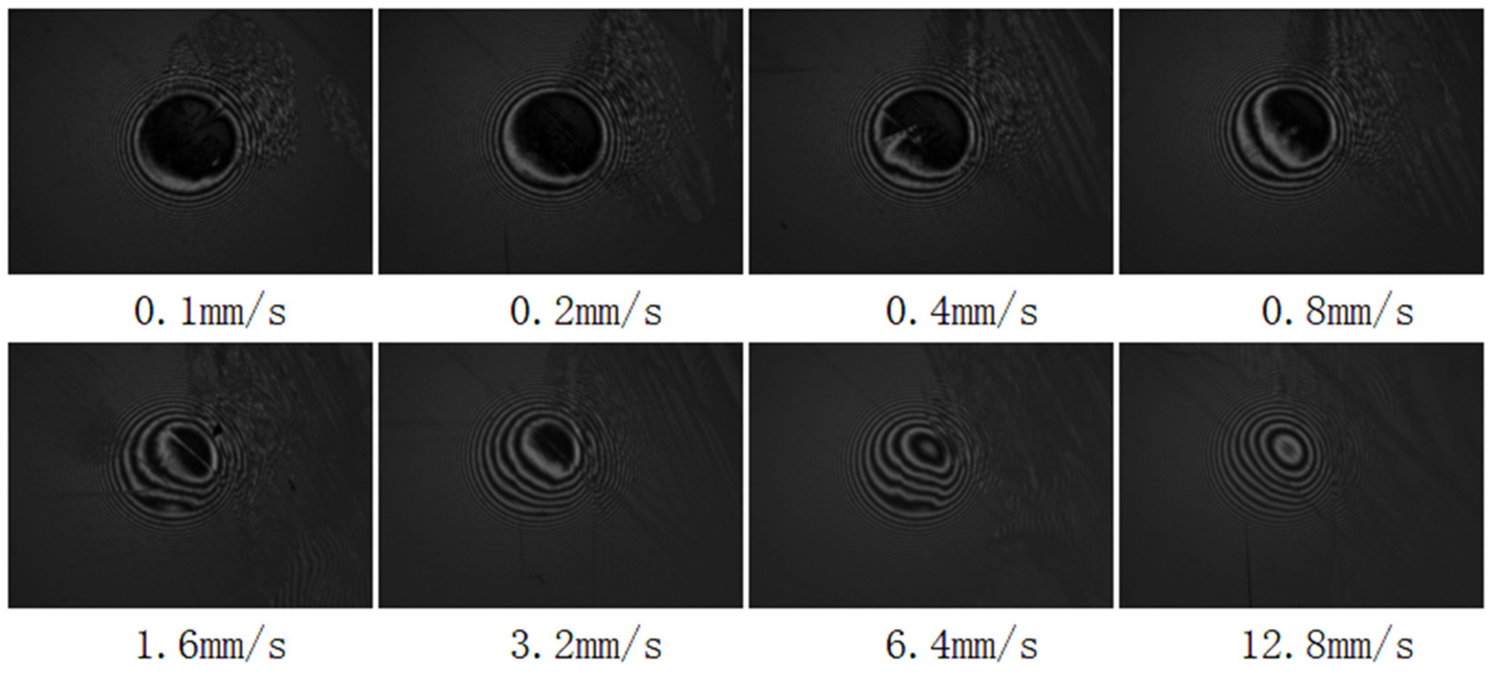
3.1.2. Surface Velocity Angle (90–180°)

As can be seen from Figure 5 and Figure 6, as the speed Angle of the disc increases from acute Angle to obtuse Angle, the shape of the lubrication film gradually changes. Clearly, the greater the velocity at an obtuse angle, the more the lubricant film topography begins to transition from being symmetrical in the direction of the suction, to tilting to the left. This asymmetry is related to the suction speed. At speeds of 3.2 mm/s or less, even when working at a large disc speed angle of 135°, the lubricating oil film asymmetry is still not significant. When the speed is increased to 6.4 mm/s, the shape of the oil film begins to clearly show an asymmetric inclination toward the steel ball’s moving side, without a dimple.

3.2. Effect of Angle Change on Oil Film State

3.2.1. Direction of Suction Speed

It can be seen in Figure 7 that at a lower speed, when the angle is 15°, the film thickness in the center area of the contact zone is relatively flat, and the oil film thickness in the outlet area decreases rapidly. With the increase in the angle, the thickness of the oil film increases, the oil boundary in the contact zone gradually disappears, the state of the lubricating oil film shows asymmetric characteristics along the direction of the winding speed, and the asymmetry becomes more and more obvious with the increase in speed. At higher speeds, when the angle is 15°, the state of the oil film is more symmetrical and a dimple appears in the inlet area, which is due to the accumulation of lubricating oil due to the interface slip caused by the different wettability. When the angle increases, the dimple in the inlet area slowly disappears, and oblique straight streaks appear, indicating that the oil film is no longer flat, but shows a wedge-shaped change, and the larger the angle, the more oblique straight streaks appear.
As the angle of the speed of the disc increases to being obtuse, when the angle between the ball speed and the disc speed are 120° and 135°, respectively, the oil film morphology shows a clear change in trend from the symmetrical suction direction to the left steel ball moving sideways, and this trend gradually weakens with the increase in the angle. At 165°, the oil film morphology is basically symmetrical. In addition, with the increase in the angle, the minimum film thickness also shows a trend of gradual reduction.
In order to study the shape and thickness of the oil film in more detail, the lubricating oil film was measured along the suction speed and along the sliding velocity to obtain two different oil film thickness curves. Firstly, from Figure 8 of the film thickness curve along the suction velocity direction, it can be seen that when it is at an acute angle, the central film thickness gradually increases with the increase of the included angle.At high speeds, the oil film profile begins to show a significant asymmetry, and the oil film thickness on the left side is significantly greater than the oil film thickness on the right, corresponding to the optical interference diagram showing that the lubricating oil film is tilted to the left, and when the angle is 45°, the oil film thickness is the largest. However, when the angle between the ball speed and the disc speed is widened to an obtuse angle, and the angle is between 120° and 135°, there is still a significant asymmetry in the oil film profile, and the thickness of the left oil film is significantly greater than that of the right oil film, and when the thickness of the oil film is lower than the acute angle. When the angle is further increased to 150° and 165°, the area with the minimum film thickness in the outlet area is relatively flat, and there is no gradient change.

3.2.2. Sliding Speed Direction

According to the film thickness curve in Figure 9, along the direction of the sliding speed, when the angle is sharp, with the increase in speed and the expansion of the angle between the ball and disc speeds, the shape of the lubricating oil film shows a gradual asymmetrical trend. With the increase in speed to 3.2 mm/s, the thickness of the oil film shows a gradually increased trend. Especially at the two angles of 45° and 60°, the inlet area and the contact area show a clear inlet dimple and the oil film curve shows a protruding form, which is consistent with the situation presented in the optical interference diagram. With the increase in speed, the film thickness continues to increase, and the dimple depth of the oil film also increases; the angle between the ball speed and the disc speed gradually expands to an obtuse angle. At low speeds, the central part of the contact zone of the elastic flow lubricant film at all four angles appears flat, which corresponds to the classic characteristics of horseshoe-shaped oil films. The speed increases, the angle increases, and the film thickness increases, but there is no fine dimple or asymmetry.
The inlet dimple is mainly due to the different properties of the glass disc surface and the steel ball surface, and when the wettability of the glass disc also changes, the ultimate shear stress is inconsistent when the lubricant is adsorbed on the two surfaces, resulting in lubricant accumulation. The lubricant adsorbed on the glass disc is the same as the up-line speed of the glass disc, and the lubricant near the glass disc pushes the lower lubricant near the steel ball to move. And because the ultimate shear stress of the lubricant near the surface of the glass disc is smaller than that near the surface of the steel ball, the lubricant close to the glass disc during movement is more likely to reach the shear limit and thus rupture, so that part of the lubricant can no longer move like the glass disc. At this time, the glass disc is still brought in by the outside of the contact area at the same speed, and the lubricant in and out balance is destroyed, meaning that these incoming lubricants accumulate at the inlet, forming a larger thickness in the oil film, manifested in the optical interference diagram for the inlet oil film dimple.
In the film thickness curve perpendicular to the direction of the suction speed, the lefthand film thickness shows an asymmetry phenomenon that is higher than the righthand film thickness, which is caused by the thermal effect of the oil film. When performing experiments with suction and sliding, although the glass disk has the same speed as the steel ball, the ball and disc’s speed angle changes. The decomposition of the ball speed and disc speed shows that in the y-axis direction, the ball and disc velocity is in the same direction and equally large, showing a pure rolling state. In the x-axis direction, the ball and disc speed is opposite and equally large, showing a zero-coil state. In the zero-coil suction motion, due to the difference in thermal conductivity at the interface of the glass disc and the steel ball, the lubricants close to the surface of the ball have a lower temperature and higher viscosity, while the lubricants close to the surface of the disc have a higher temperature and lower viscosity. Therefore, under this working condition, as the film thickness on the moving side of the steel ball increases, it is subjected to more friction. When the movement of low-viscosity lubricants is hindered by high-viscosity lubricants, it will lead to an increase in pressure in the area, resulting in an increase in local elastic deformation, which eventually leads to the accumulation of lubricants, which is also the mechanism of forming dimples under zero-roll suction conditions. In addition, because the friction pair has a certain degree of viscosity, and the friction force changes with time, as the friction coefficient decreases, its effect on the flow resistance of the lubricating fluid gradually decreases, resulting in a deeper dimple. Therefore, in the direction perpendicular to the suction speed, under the working condition of orthogonal suction and sliding, when in a state equivalent to zero suction, the lubricant will gradually accumulate on the moving side of the steel ball with a high viscosity, resulting in the film thickness on the left side of the steel ball being significantly higher than that on the right side.

3.2.3. The Central Membrane Is Thick

From Figure 10 of the central film thickness, it can be seen that under the same load and the same speed, when the angle between the ball and disc’s speeds is an acute angle, the central film’s thickness tends to increase with the increase in the angle of the disc. However, if and only if it is obtuse, it shows a rapid decrease in the thickness of the central film. The decrease in the film’s thickness when the disc angle increases to an obtuse angle is caused by the thermal effect of the contact zone. From the vector diagram of the speed model of Figure 2, it can be seen that in the case that the absolute value of the speed of the glass disk and the steel ball is equal, the suction speed (UE) is constant, the sliding speed (us) will increase with the increase in speed, and the sliding speed (us) is the main reason for the occurrence of the thermal effect; the larger the us, the more significant the thermal effect, the greater the heat production during the movement of the lubricant, the temperature rises, the viscosity decreases, and the thickness of the oil film decreases. Therefore, when the suction speed and sliding speed are orthogonal, the increase in the angle has an inhibitory effect on the increase in the lubricating oil film’s thickness, and the inhibition effect is related to the size of the ball and disc speed angle. When the angle is an acute angle, the increase in the angle has no significant effect on the film thickness reduction [27], and when the angle is an obtuse angle, the angle has a greater effect on the decrease in the film’s thickness, which is manifested as the sliding velocity (us) increases with the increase in the angle, and the greater the effect on the film thickness change. When the angle between the discs is an acute angle, the inhibitory effect of the thermal effect is not obvious, and the interface slip at this time mainly affects the increase in the thickness of the central film.

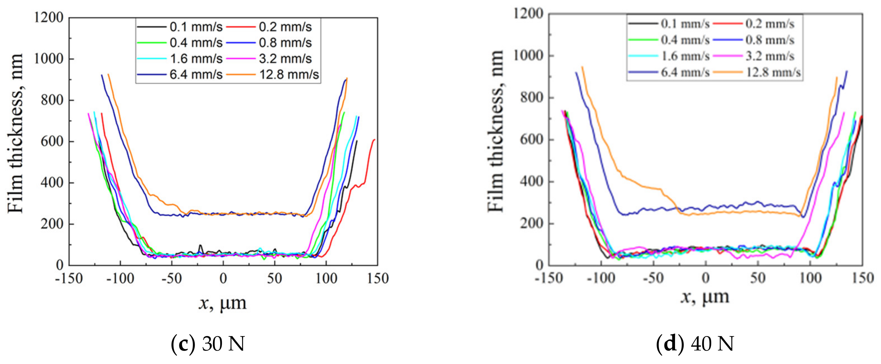
3.3. Effect of Load Variation on Oil Film State

In order to explore the influence of load on the film thickness of the lubricating oil, the film thickness of the oil film under the same working condition was compared with four different loading methods, and the results are shown in Figure 11 and Figure 12. It can be found that the thickness of the oil film increases with the increase in the load. Under the load condition of 20 N, there are obvious bulges along the upper half of the sliding velocity oil film thickness curve at a speed of 1.6 mm/s, which indicates that there is significant lubricant accumulation in this area, resulting in a sudden increase in the oil film’s thickness in this area. With the increase in load, it can be found that when the speed is 3.2 mm/s, the uplift in the front section of the film thickness curve moving towards the center is more obvious, and the dimple depth increases first and then decreases with the increase in the suction speed. In addition, it can also be found that even when the speed reaches 6.4 mm/s under a high load, the front end of the film thickness curve still has a bulge phenomenon, indicating that the high load helps the formation and strengthening of the dimple, and the central part of the contact zone of the elastic lubricating oil film under the action of the four loads is relatively flat along the direction of the winding speed, which is consistent with the classic horseshoe-shaped oil film characteristics.
When the angle is obtuse, the influence of the load on the thickness of the lubricating oil film is explored, and the change in the oil film thickness under different loads is compared when the speed and angle variables are consistent. As can be seen in Figure 13, there is a clear difference from the acute angle as the load increases, but the minimum film thickness of the oil film remains basically unchanged. The inhibition of the high load on the increase in oil the film’s thickness is also verified.

4. Conclusions

This paper mainly introduces the changes in entrainment speed, surface velocity angle, and load under the interface of surface wettability difference, using PB1300 in the orthogonal working condition of the glass disk velocity direction and steel ball velocity direction. The patterns of film thicknesses and film shapes were analyzed. The main conclusions can be summarized as follows:
(1) Under the same load and velocity angle, the lubricating oil film morphology shows an atypical asymmetry with the increase in speed, and when the angle of the ball and disc speed is an acute angle, with the increase in speed, an oblique spindle shape appears in the optical interference image. However, when the angle is obtuse, with the increase in speed, the shape of the oil film does not change significantly and there is no dimple. This phenomenon can be explained by thermal effects and interface slippage, which are related to the thermal conductivity of the two interfaces.
(2) When the angle between the discs is an acute angle, the inhibition of the thermal effect is not obvious, and the interface slip at this time plays a major role in increasing the thickness of the central film, and the accumulation of the lubricating oil occurs along the section of the sliding speed. When the angle between the discs is obtuse, the increase in angle has a great impact on the decrease in film thickness, and the main reason is attributed to the thermal effect, temperature increase, and viscosity decreases, resulting in a decrease in film thickness.
(3) At an acute angle, an oblong dimple appears at the entrance to the contact zone, and the main reason for this phenomenon is the interface slippage. At the same speed, the greater the load, the higher the wedge clearance near the entrance area. When the angle is obtuse, with the increase in load, the minimum film thickness of the oil film is basically unchanged. The contact area is always flat and there is no inlet dimple.
(4) On the difference in surface wettability, there is a reduction in wettability. The wedge-shaped gap characteristics represented by the inlet dimples and transverse inclined stripes generated by the PB1300 lubricant are more pronounced compared to the original surface conditions. This indicates an enhanced interface slip at the AF interface.

Author Contributions

Conceptualization, Z.W. and J.Z.; methodology, Z.W.; software, Z.W.; validation, Z.W., S.W. and W.W.; formal analysis, J.Z.; investigation, S.W.; resources, J.Z.; data curation, Z.W.; writing—original draft preparation, Z.W.; writing—review and editing, Z.W.; visualization, W.W.; supervision, Q.C.; project administration, J.Z.; funding acquisition, J.Z. All authors have read and agreed to the published version of the manuscript.

Funding

The authors would like to express their thanks for the financial support from the Natural Science Foundation of Shandong (Project No. ZR2020ME135).

Data Availability Statement

Not applicable.

Conflicts of Interest

The authors declare no conflict of interest.

References

  1. Chiu, Y.P.; Sibley, L.B. Contact Shape and Non-Newtonian Effects in Elastohydrodynamic Point Contacts. Lubr. Eng. 1972, 28, 48–60. [Google Scholar]
  2. Kaneta, M.; Nishikawa, H.; Kameishi, K. Effects of Elastic Moduli of Contact Surfaces in Elastohydrodynamic Lubrication. J. Tribol. 1992, 114, 75–80. [Google Scholar] [CrossRef]
  3. Ehret, P.; Dowson, D.; Taylor, C.M. On Lubricant Transport Conditions in Elastohydrodynamic Conjuctions. Proc. R. Soc. Lond. A 1998, 454, 763–787. [Google Scholar] [CrossRef]
  4. Qu, S.; Yang, P.; Guo, F. Theoretical Investigation on the Dimple Occurrence in the Thermal EHL of Simple Sliding Steel-Glass Circular Contacts. Tribol. Int. 2000, 33, 59–65. [Google Scholar] [CrossRef]
  5. Yang, P.; Qu, S.; Chang, Q. On the Theory of Thermal Elastohydrodynamic Lubrication at High Slide-Roll Ratios: Line Contact Solution. J. Tribol. 2001, 123, 36–41. [Google Scholar] [CrossRef]
  6. Cameron, A. The Viscosity Wedge. ASLE Trans. 1958, 1, 248–253. [Google Scholar] [CrossRef]
  7. Murch, L.E.; Wilson, W.R.D. A Thermal Elastohydrodynamic Inlet Zone Analysis. J. Lubr. Tech. 1975, 97, 212–216. [Google Scholar] [CrossRef]
  8. Wilson, W.R.D.; Sheu, S. Effect of Inlet Shear Heating due to Sliding on Elastohydrodynamic Film Thickness. Trans. ASME J. Lubric. Technol 1983, 105, 187–188. [Google Scholar] [CrossRef]
  9. Lord, J.; Larsson, R. Effects of Slide-roll Ratio and Lubricant Properties on Elastohydrodynamic Lubrication Film Thickness and Traction. Proc. Inst. Mech. Eng. Part J J. Eng. Tribol. 2001, 215, 301–308. [Google Scholar] [CrossRef]
  10. Omasta, M.; Krupka, I.; Hartl, M. Effect of Surface Velocity Directions on Elastohydrodynamic Film Shape. Tribol. Trans. 2013, 56, 301–309. [Google Scholar] [CrossRef]
  11. Omasta, M.; Krupka, I.; Hartl, M. Study of Elastohydrodynamic Film Shape Under Different Directions of Velocity Vectors. In Proceeding of ASME/STLE 2011 International Joint Tribology Conference, Los Angeles, CA, USA, 24–26 October 2011; pp. 401–403. [Google Scholar]
  12. Omasta, M.; Krupka, I.; Hartl, M. Effect of sliding direction on EHL film shape under high sliding conditions. Tribol. Trans. 2016, 60, 87–94. [Google Scholar] [CrossRef]
  13. Yagi, K.; Vergne, P.; Nakahara, T. In Situ Pressure Measurements in Dimples Elastohydrodynamic Sliding Contacts by Raman Microspectroscopy. Tribol. Int. 2009, 42, 724–730. [Google Scholar] [CrossRef]
  14. Guo, F.; Wong, P.L. Experimental Observation of a Dimple-wedge Elastohydrodynamic Lubricating Film. Tribol. Int. 2004, 37, 119–127. [Google Scholar] [CrossRef]
  15. Kaneta, M.; Yang, P. Effects of the Thermal Conductivity of Contact Materials on Elastohydrodynamic Lubrication Characteristics. J. Mech. Eng. Sci. 2010, 224, 257787. [Google Scholar] [CrossRef]
  16. Bruyere, V.; Fillon, N.; Morales, G.E.; Vergne, P. Computational Fluid Dynamics and Full Elasticity Model for Sliding Line Thermal Elastohydrodynamic Contacts. Tribol. Int. 2012, 46, 3–13. [Google Scholar] [CrossRef]
  17. Black, D.T. Slip between a liquid and a solid: D.M. Tolstoi’s theory reconsidered. Colloids Surf. A 1990, 47, 135–145. [Google Scholar]
  18. Vinogradova, O. Drainage of a thin liquid film confined between hydrophobic surfaces. Langmuir 1995, 11, 2213–2220. [Google Scholar] [CrossRef]
  19. Xiang, G.; Yang, T.Y.; Guo, J.; Wang, J.X. Optimization transient wear and contact performances of water-lubricated bearings under fluid-solid-thermal coupling condition using profile modification. Wear 2022, 502–503, 204379. [Google Scholar] [CrossRef]
  20. Tretheway, D.C.; Meinhart, C.D. Apparent fluid slip at hydrophobic microchannel walls. Phys. Fluids 2002, 14, 9–12. [Google Scholar] [CrossRef]
  21. Choo, J.H.; Spikes, H.A.; Ratoi, M. Friction reduction in low-load hydrodynamic lubrication with a hydrophobic surface. Tribol. Int. 2007, 40, 154–159. [Google Scholar] [CrossRef]
  22. Piotr, W. Investigation of energy losses of the internal combustion engine taking into account the correlation of the hydrophobic and hydrophilic. Energy 2023, 264, 126002. [Google Scholar]
  23. Ma, J.; Liu, Y.C.; Zhang, N.; Zhang, W.J. Wettability transition and tribological properties of hydrophobic alloy surfaces prepared by one-step method. Tribol. Int. 2023, 178, 108020. [Google Scholar] [CrossRef]
  24. Piotr, W. Reduction of friction energy in a piston combustion engine for hydrophobic and hydrophilic multilayer nanocoatings surrounded by soot. Energy 2023, 271, 126974. [Google Scholar]
  25. Wang, Y.X.; Yuan, C.; Zhou, K.; Gu, Q.L.; Jing, W.H. Construction of Janus silicon carbide membranes with asymmetric wettability for enhanced antifouling in water-in-oil emulsification process. J. Membr. Sci. 2023, 671, 121389. [Google Scholar] [CrossRef]
  26. Lu, H.W.; Zhang, J.; Liu, C.; Guo, F. Experimental study of limited oil supply on lubrication characteristics under velocity intersection working condition. Tribology 2022, 43, 178–188. [Google Scholar]
  27. Li, X.M.; Zhou, G.Y.; Guo, F. Experimental Investigation into Enhancement of Lubricant Replenishment Induce by Angled Entrainment. J. Mech. Eng. 2020, 56, 225–232. [Google Scholar]
  28. Ni, Q.B.; Zhang, J.J.; Guo, F. Experimental investigation of effects of surface speed effect on EHL. Lubr. Eng. 2018, 43, 37–39. [Google Scholar]
  29. Liu, H.C.; Guo, F.; Zhao, G.L. A Dichromatic Interference Intensity Modulation Approach to Lubricating Film Thickness Measurement. Tribology 2015, 35, 282–287. [Google Scholar] [CrossRef]
  30. Luo, J.B.; Wen, S.Z.; Huang, P. Thin film lubrication. Part I Study on the transition between EHL and thin film lubrication using a relative optical interference intensity technique. Wear 1996, 194, 107–115. [Google Scholar] [CrossRef]
  31. Guo, F.; Wong, P.L.; Fu, Z. Interferometry measurement of lubricating films in slider-on-disc contacts. Tribology 2010, 39, 71–79. [Google Scholar] [CrossRef]
  32. Zhang, J.J. Study on Non-Collnearentrainment Speed, Thermal Viscosity Wedge and Interface Slippage of Elastohyrodynamic Lubrication; Qingdao Technology University: Qingdao, China, 2022. [Google Scholar]
Figure 1. Schematic diagram of the measurement structure of photo elastic flow lubricant film.
Lubricants 11 00381 g001
Figure 2. Vector illustration of velocity model.
Lubricants 11 00381 g002
Figure 3. Oil film morphology with velocity variation at a 45° angle between surface velocities of AF hydrophobic interface, PB1300, 20 N.
Lubricants 11 00381 g003
Figure 4. Oil film curve with speed at AF hydrophobic interface at a surface velocity angle of 45°, PB1300, 20 N.
Lubricants 11 00381 g004
Figure 5. Oil film curve with speed at AF hydrophobic interface at a surface velocity angle of 135°, PB1300, 20 N.
Lubricants 11 00381 g005
Figure 6. Oil film morphology with velocity at the surface velocity angle of 135°, under the AF hydrophobic interface, PB1300, 20 N.
Lubricants 11 00381 g006
Figure 7. Optical interferogram of the change in angle when the surface velocity is in the opposite direction at the AF interface, PB1300, 20 N.
Lubricants 11 00381 g007
Figure 8. Oil film thickness curve with same load and speed, and different angle and x direction, PB1300, 20 N.
Lubricants 11 00381 g008
Figure 9. Oil film thickness curve with same load and speed, and different angle and y direction, PB1300, 20 N.
Lubricants 11 00381 g009
Figure 10. At different speeds, the thickness of the central film changes with the angle, PB1300, 20 N.
Lubricants 11 00381 g010
Figure 11. Morphology of oil film with load at different speeds, PB1300, δ = 15°.
Lubricants 11 00381 g011
Figure 12. Film thickness curve with 15° velocity angle and with load, PB1300.
Lubricants 11 00381 g012
Figure 13. Film thickness curve with 135° velocity angle and with load, PB1300.
Lubricants 11 00381 g013aLubricants 11 00381 g013b
Table 1. Physical properties of PB1300 lubricant.
Name of the OilDensity ρ
(kg·m−3)
20 °C
Dynamic Viscosity l
(Pa·s)
20 °C
PB1300896117.0
Disclaimer/Publisher’s Note: The statements, opinions and data contained in all publications are solely those of the individual author(s) and contributor(s) and not of MDPI and/or the editor(s). MDPI and/or the editor(s) disclaim responsibility for any injury to people or property resulting from any ideas, methods, instructions or products referred to in the content.

