1. Introduction
High-power transmissions which are designed for modern highly efficient turbofans extensively exploit planetary gears due to their compact design. In most cases, to save space, the planetary gears are supported by integrated bearings. While this solution is extremely competitive both in terms of cost and weight, the planets are subjected to rolling contact fatigue (RCF) conditions. The propagation of micro-cracks starting from the outer race, namely the internal cylindrical surface of the planet gear, could lead to spalling failures. In this framework, the research project has, as its main objective, to provide innovative, effective and validated criteria for the design and assessment of more reliable planet bearings for aerospace application. The project is aimed at analyzing the problem from a damage tolerance perspective. This kind of analysis is designed to estimate the risk of a catastrophic failure in case of development of subsurface propagation of cracks driven by shear stresses. Considering that RCF is a grey area where little data are publicly available, the project is targeted at covering this lack within the literature.
The prediction of the crack growth path, aimed at the maximization of the reliability, can be achieved only if several influence parameters are considered during the analysis: among others, the properties of the base material, the geometry of the component, the heat treatment process, the profile of the residual stresses and the hardness profile, with its case-core transition, etc. The validation of the proposed design criteria will be performed by means of full-scale test articles subjected to load conditions representative of the real application.
The full-scale tests will be performed on a special test rig based on a standard back-to-back bench. The actual design differs from the standard FZG test rig (ISO 14635-1 [
1]) by the presence of a third shaft on which an idle gear—representing the planet with integrated bearing—is mounted.
The housing of the gearbox is manufactured with welded steel plates and will include a lubrication system reproducing the typical oil supply conditions of the planetary gearbox, namely oil injection. The present paper focuses on the study of the lubrication system of the rig to ensure the proper lubricant supply to the idle gear and its integrated bearing during the RCF tests. Concerning the main testing article, namely the planet bearing, different oil injection directions have been analyzed.
The simulations of the whole system on different scale levels (from the main gear arrangement to the single rolling elements of the bearing) was possible thanks to the development and exploitation of an innovative mesh-handling technique (GRAMC Global Remeshing Approach with Mesh Clustering) combined with Rigid Mesh Motions (RMM) and an effective adoption of Arbitrary Mesh Interfaces (AMIs). The whole methodology was implemented in the open-source environment OpenFOAM®. Its GNU (General Public License) allowed the massive parallelization of the computation.
2. State of the Art
On the one side, the design of a gearbox can be nowadays considered a standard practice. Several standards [
2,
3] are available. For special geometries, which are not covered by the latter standards, the adoption of Finite Element Analyses (FEA) is a widespread approach exploited by multiple scholars. Examples of application of FE cover many aspects of gear design, ranging from the rough sizing to the determination of the NVH behavior. Li et al. [
4] have used FEA to study the tooth root crack propagation in Gears. Li [
5] has studied the contact and bending strength via FE simulations including in the model the manufacturing errors. Many other scholars, including which Liu et al. [
6], have determined the meshing stiffness of the gear train using numerical approaches. Concli et al. [
7] used FEA to study the dynamic behavior of a planetary gear train and to monitor the crack initiation site [
8]. Examples in this sense are multiple.
On the other side, the design of the lubrication is still a hard challenge. It is common practice to realize a first prototype and perform experimental test on it to fine tune the injection position and direction, the flow rate, the lubricant, etc. In this regard, some valuable papers give some indication (Dindar et al. [
9,
10,
11], Mauz [
12], Changenet et al. [
13]) on the expected churning losses under different lubrication conditions. More recently, the advancements in computer science and the related growing computational power have led to the development of numerical approaches also concerning lubrication. Gorla et al. [
14] presented a comprehensive review of the available CFD approaches. Among them, Smooth Particle Hydrodynamic (SPH) and Finite Volume (FV) were identified as the most promising ones. Examples in this sense were presented by several authors. Marchesse et al. [
15] studied the flow in simple spur gears via FV. The same method was exploited by Concli et al. [
16] to study the squeezing power losses and the lubrication in the mating region. Good achievements were also presented by Bianchini et al. and Fondelli et al. [
17,
18] concerning the oil injection of high-speed gears. Peng et al. [
19,
20,
21] investigated the oil flow and the power losses in hypoid gears. Hu et al. [
22] and Lu et al. [
23,
24] built a CFD model of an intermediate gearbox of a helicopter to study the power losses and the temperature profile on the teeth.
Zhigang et al. [
25] and Rahmatjan et al. [
26] used the SPH method instead. Liu et al. [
27] and Ji et al. [
28] were able to properly capture the main fluxes around a spur gears pair with an SPH approach. From this pioneering research emerged the fact that SPH is not sufficiently accurate to properly capture the lubricant behavior in terms of power losses and local fluxes but is suitable only to have a rough idea of the main lubricant stream in the gearbox. On the contrary, FV based approaches seem to be very accurate but also extremely time consuming and, in most cases, not applicable to real industrial applications.
To overcome these limitations, some new methods were developed. Legrady et al. [
29], for instance, developed new specific boundary conditions (BC) to better capture the velocity profile near the boundaries. On the FV side, the huge computational efforts required in order to simulate dip lubricated (multiphase) gear lubrication, seem to be strongly related to the fact that, during the simulation, the computational grid needs to be frequently updated to counteract the domain deformation and topology changes. The traditional remeshing algorithms [
30] lead typically to a mesh quality degeneration and the need to reduce the time step to ensure convergency. These algorithms basically remove only the cells which quality results degenerated. This creates a sort of hole in the grid (which shape could not be controlled a priori) that will successively be filled with new elements. While this process is effective, it typically produces smaller and smaller elements. Consequently, the time-step should be gradually decreased to meet the convergence criteria, namely keeping the Courant number below one.
In this framework, Concli et al. [
31,
32] have developed a more controllable approach (so called global remeshing approach—GRA) which allows the grid parameters to be kept constant during the simulation. The main idea is to substitute the entire grid instead of removing and replacing the distorted elements only. While this procedure could be seen as less efficient, the a priori knowledge of the shape of domain to be meshed ensures, on the one hand, the possibility to better parametrize and control the grid resulting in a faster meshing, and, on the other hand, ended up with a grid whose element size remains constant for the entire simulation. This latter fact ensured the possibility to maintain a constant time-step for the entire computation with significant time savings. Recently, Mastrone et al. [
33] have further improved the GRA method (GRA
MC—GRA with mesh clustering) using a recursive adoption of few meshes created a priori. This approach has led, for the reference configuration (a back-to-back test rig), to a speed up of the simulation by a factor of x328. This significant improvement in computational efficiency has paved the way for the possibility of simulating multistage gearboxes [
34] and grease lubrication [
35] in a reasonable amount of time. Moreover, the application of CFD not only to study gears but also to bearings seems to be a growing trend. Maccioni et al. published a review paper first [
30], and successively the results of a numerical study of the lubricant aeration in a tapered roller bearing and their experimental validation [
36]. Other records have been published by Bohnert et al. [
37], Wen et al. [
38], Feldermann et al. [
39], Adeniyi et al. [
40], Liebrecht et al. [
41], Yan et al. [
42] and by Profito et al. [
43].
With these premises, the goal of this work was to run the first FV simulations ever of a complete system, including the bearings, to verify the proper lubricant supply to the gears and to the testing bearing. This was achieved exploiting the GRAMC approach. These simulations are aimed to understand the best nozzle inclination to ensure the optimal lubrication of the bearing.
3. Description of the System
In
Figure 1, the 3D view of the considered system and its 2D schematization are shown. The test rig is a modified version of the standard back-to-back test bench used for pitting and efficiency tests on gears. The rig exploits the mechanical recirculation principle to load the gears [
44]. The rotation of the system is ensured by an electric motor that should supply the power losses only.
The original rig consists of two gearboxes (testing and slave) having the same gear ratio and center distance. The corresponding gears of the two stages are connected via two parallel shafts. In the present version, the testing gearbox was modified and now consists of five gears instead of two. The input shaft drives the first pinion (drive gear) that engages with an idle gear (main gear). The power is transmitted to the driven gears (identical to the first pinion). An idler shaft transmits the power to the return gear #2 which engages with the return gear #1. The latter is connected via an external shaft to the driving gear of the slave gearbox. The mechanical loop is closed by a second external shaft connecting the driven gear of the slave gearbox to the first pinion. All the shafts are supported by roller bearings.
The lubrication of the system is ensured by a hydraulic circuit equipped with a heater/cooler to control the oil temperature. The synthetic lubricant is injected into the gear engagements from both directions. Moreover, to ensure the proper lubrication of the main bearing, two additional nozzles were mounted in front of the bearing. Those nozzles inject the lubricant directly into the bearing. Three nozzle orientations have been studied: (1) parallel to the axis; (2) inclined by 10 degrees on the right (the oil jet has an axial component and a tangential component with the same direction of the cage tangential speed; inclined by 10 degrees on the left (the oil jet has an axial component and a tangential component with the opposite direction with respect to the cage tangential speed.
4. Modelling of the System
The system is subdivided into two regions, as highlighted by the red and green dashed rectangles of
Figure 2. The object of the current investigation is the region highlighted with the green rectangle. This domain is composed of the drive gear, the main gear with the main bearing incorporated, and the driven gear. The design characteristics of the gears are summarized in
Table 1. The bearing incorporated in the main gear is the Schaeffler NUP2207-E-XL-TVP2, whose characteristics are reported in
Table 2.
The synthetic oil PETRONAS ZC 601 FF was used as lubricant. It has good anti-wear and fuel economy characteristics, high thermal stability, shiftability and cleanliness. Dedicated orifices and channels ensure that the gear mesh sites, and the bearing are constantly lubricated with a jet of oil. Its properties are reported in
Table 3.
4.1. Governing Equations
The Finite Volume Method [
45] opensource software OpenFOAM
® v7 [
46] was used to implement the CFD model of the system.
The modeling of incompressible immiscible multiphase flows presents complex challenges [
47,
48]. Indeed, the interface separating the two fluids is extremely thin and discontinuous, and the density variation across the interface is large. Moreover, reactions and phase changes might occur and should be considered.fix.
The Volume of Fluid (VOF) model [
49] was used to simulate the two-phase oil-air condition. The sum of the oil and air volume ratios (αoil and αair, respectively) in each control volume is equal to one.
When αoil = 1, the control unit is full of oil; when αoil = 0, only air is present in the control unit; for any value between 0 and 1, in the control unit an oil–air interface is present. The solution of the continuity equation of the volume fraction allows to trace the oil–air interface.
The Multidimensional Universal Limiter with Explicit Solution (MULES) [
50] algorithm was used to achieve a better boundedness of the volume fraction field. The original formulation of the MULES is explicit, which imposes terrible constraints on the Courant number, while the new formulation of the MULES, Predictor-Corrector Semi-Implicit MULES, overcomes the limitations of the explicit method. A dummy velocity field (u
c) acting perpendicular to the interface is added in the conservation equation of α.
where
uc = min(c
α|
u|, max (|
u|))⋅n), being c
α the coefficient that controls the magnitude of the compression (usually set between 0 and 2).
The generic property ϕ (as viscosity and density) of the equivalent fluid is calculated as
Finally, the continuity and the momentum equations for the oil–air mixture are
The weighted average properties are used so that the two conservation equations are associated with the continuity equation of the volume fraction [
50,
51].
4.2. Implementation of the CFD Model
In this paragraph, the implementation of the numerical model of the system in OpenFOAM® is presented. A detailed description of the geometry partition, the meshing approach, and the mesh-handling technique are presented in the next chapters.
4.2.1. Geometry
In order to build the CFD model of the system, in a first step the negative of the CAD model has to be created, i.e., only the regions where the lubricant can actually flow have to be considered. Small-scale features such as screws, springs and sealings were neglected, as they are not expected to have a noteworthy impact on the oil distribution. The geometry was further cleaned by removing chamfers, edges and small clearances since a very fine mesh would be necessary to resolve the related oil flows and no impact on the main lubricant distribution in the gearbox is expected. The effect of these small-scale features might be better investigated in dedicated sub-models. The gears were scaled radially to 99% of their nominal size. This operation enables to slightly enlarge the very small gap between the teeth flanks, thus avoiding numerical singularities and poor-quality cells in the gear meshing region, and it is actually required for all finite volume-based simulations of intersecting objects.
4.2.2. Domain Partitioning and Meshing Approach
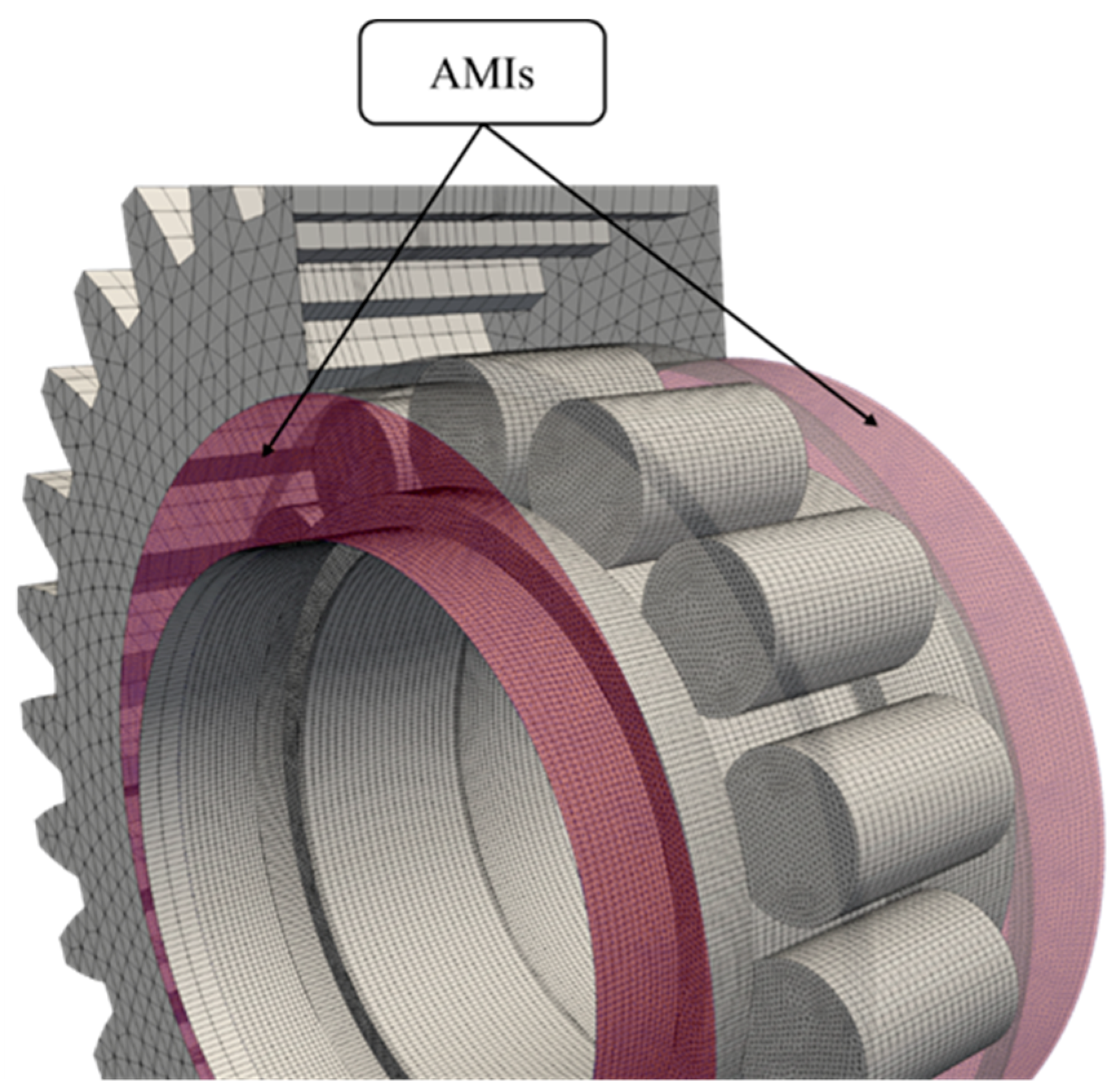
The system under investigation is composed of spur gears and cylindrical roller bearings. Hence, it is possible to mesh the domain with an extruded approach. Extruded meshes are preferable over tetrahedral ones, since they exhibit higher quality, lower memory usage, and faster calculation times. In a first step, the domain was decomposed into four subdomains which were meshed separately. Arbitrary Mesh Interfaces (AMIs) [
49] were introduced to connect the adjacent cell zones numerically. Indeed, at the interface the nodes are not conformal, but the AMIs ensure the continuity of the field variables across the mesh discontinuities. In
Figure 3 the four subdomains are shown with different colors. The bearing domain (colored in red) is inside the gear domain (colored in orange) and has been magnified for visualization purposes.
The green and the light-blue subdomains are composed of the external parts of the gearbox and do not undergo any deformation. Their geometry is relatively simple and extruded grids can be generated with few partitions. On the other side, the orange and the red subdomains contain the gears and the roller bearings, respectively. The complexity of these subdomains requires the dedication of some effort in the partitioning phase. In the gear’s domain, planes in correspondence of the gear sides and around the nozzles were used to partition the domain. The gear profiles were extruded and used to further partition the domain in the axial direction. In the bearing domain, planes in correspondence of the rollers position were defined, and the roller profiles were extruded. These operations allowed to generate a swept mesh in all the four sub-domains. A local refinement around the jet positions was implemented to avoid numerical diffusion of the injected oil. In
Figure 4, the longitudinal and the cross views of the assembled mesh are reported.
A detailed view of the bearing domain inside the main gear is reported in
Figure 5. The outer ring is set with some transparency to better visualize the rollers positioning.
The final mesh is composed of about 2.5 M prismatic elements. The extensive pre-processing phase allowed the obtention of a high-quality mesh composed of extruded elements only. This is of primary importance, especially in simulations involving multiphase flows and moving boundaries, as the one object of this analysis. This procedure reduces the mesh generation time significantly: indeed, the whole 3D mesh is created starting from 2D surface meshes, which are then extruded to create swept elements. In this way, a 2.5D discretization is accomplished. The open-source tools Python [
52] and Salome [
53] were used for the geometry and mesh generation. In
Table 4, the quality parameters of the mesh are reported.
4.2.3. Mesh-Handling Technique
To simulate the considered system, a dynamic mesh-handling approach was introduced. In fact, due to the gears engaging with each other, the mesh is deformed and must be replaced at regular angular positions with a new valid one. A well-known remeshing algorithm is the Local Remeshing Approach (LRA), which can be found in some commercial software. It is based on the automatic remeshing of the distorted cells that should be substituted with new ones. The regeneration considers the imposed mesh quality that should be kept throughout the simulation. The LRA is usually associated with high computational costs and the need for High Performance Computing (HPC). Indeed, since the remeshing process is handled mainly by the code, the user does not have a direct control on the new elements that are generated. Sometimes, significantly smaller elements with respect to the original ones are created, thus influencing the maximum allowable time-step and the Courant number, which should be kept lower than one to have a stable simulation and obtain physical results.
An alternative to the LRA is the Global Remeshing Approach with Mesh Clustering (GRA
MC) [
33,
35], which was implemented by the authors in the open-source environment OpenFOAM
® to overcome the limitations of the previous approach. This algorithm foresees the solution of the Laplace smoothing equation and the pseudo solid equation (linearization of the motion equations for small deformations) to describe the motion of the boundaries.
where
z is the prescribed motion, γ is the diffusivity, x is the grid’s nodes position and t is the current timestep. The GRA
MC is based on the preliminary computation of a set of mesh that covers one complete engagement cycle. Then, the wheels find themselves in the same position as the first mesh; thus, it possible to recursively use the computed mesh set for the entire simulation. In this way, the computational effort of the remeshing process is drastically reduced. Another advantage of this mesh-handling technique is related to the fact that the user has direct control of the elements size. Therefore, the mesh quality can be better controlled with respect to the LRA. Finally, the field variables are interpolated from mesh to mesh following an inverse distance weighting second order method. From the mesh deformation tests, it emerged that five meshes are necessary to complete one complete gear meshing. Afterwards, the first mesh could be reused, and the simulation could continue.
As can be noticed, the algorithm is based on the mesh-to-mesh interpolation of the field variables. The mapping process follows a consistent option since each successive domain is perfectly conformal with the previous one. Furthermore, the interpolation errors are minimized because of the very similar grids that have been computed. The whole simulation is managed by a Bash [
54] script. For this algorithm, it is necessary to coherently set the velocity and the time libraries as to force the passage of the wheels in the computed control positions.
For what concerns the motion of the bearing, a different mesh motion strategy was applied. For this component, it is not necessary to deform the mesh. In fact, as demonstrated by the authors [
55], the Rigid Mesh Motion (RMM) is the most efficient approach to simulate roller bearings. This approach does not foresee topological changes and, therefore, it does not require the implementation of a remeshing approach, as was performed for the gears. The whole grid is set into rotation at the rotational speed of the cage. The rotational speeds of the inner and outer ring were defined in the relative reference frame. A dedicated boundary condition was coded to correctly apply the roto-translation of the rollers. By exploiting this approach, only one mesh was computed. The numerical grid was then appropriately synchronized with the gear motion. In
Figure 6, the velocity contour of the bearing and the gears is shown. The kinematics of both components are correctly reproduced.
Table 5 shows the BCs. The column meshMotion refers to the RMM-domain, where the entire mesh was set into rotation with the speed of the cage (ω
C). pointMotion refers to the imposed motion of the points of the patches. In the GRA
MC-domain, the points of the Gear- and the Shaft-boundaries are set into rotation (ω
G/ω
S). In the RMM-domain, the motion of the points of the Rollers-, InnerRing- and OuterRing-patches are read from the motion of the mesh (the relative pointMotion is zero pM
rel = 0). The fourth column describes the artificial velocities. For the Gear- and the Shaft-boundaries, these velocities correspond to the ones used for moving the boundary points (U
rel = 0). In the RMM-domain, the absolute velocity of the InnerRing was set to zero (independently from the motion of the grid—U
(abs) = 0), while the one of the OuterRing was set considering the contribution given by the RMM, the one of the pointMotion (zero) and from U (U
rel = {ω
OR – ω
C}∙R
OR) resulting in the final value (
Figure 6). Finally, the Rollers-velocity is constructed summing the pure translation (RMM ω
C + pM
rel = 0) and the purely rotational contribution (U
rel = −ω
RCIR∙R
R) around the roller axis.
4.2.4. Operating Condition and Numerical Settings
At the investigated operating condition, the gears rotate at 3000 rpm. The whole mesh of the bearing rotates rigidly at the mean velocity of 1783 rpm. The velocity of the rollers was calculated by adding to the grid motion the pure rotation around their axis. The velocity of the outer and inner rings was defined in the rotating reference frame by adding or subtracting the proper velocities. The oil is injected in the system with a volumetric flow rate of 3.91 L/min.
The PIMPLE (merged PISO-SIMPLE) algorithm was adopted because it allows the use of relatively high time steps with relaxation (SIMPLE) and the maintenance of the temporal information (PISO). In
Table 6, the numerical settings used in the simulation are summarized.
The simulations were run on an INTEL® CORE™ i7-6850K CPU, 6 Cores, 3.60 GHz machine requiring about one week to achieve the regime condition.
5. Discussion
The simulations have been analyzed extensively with the main purpose of understanding if the actual lubrication system that exploits six nozzles (two for each gear pair contact and two for the main bearing) results appropriate.
Figure 7 clearly shows how the oil jets penetrate in the engagement region ensuring sufficient lubrication of the meshing gears. In particular, looking at the local velocities of the upper oil jets lubricating the gears, different behaviors can be appreciated. The left-hand side nozzle injects the lubricant from the gear approaching direction. The depressurization caused by the stream effects of the meshing gears promotes an acceleration of the oil stream that is sucked into the contact. On the right-hand side, instead, the upper nozzle injects the lubricant from the gear recess direction. The oil meets the upcoming air stream generated by the meshing teeth. The stream is consequently suddenly slowed down. This causes a dispersion of the jet that becomes conical. While this phenomenon prevents a deep penetration of the jet into the contact, it ensures a wider wetting of the flanks. On the contrary, the lower nozzle that lubricates the right-hand side gear contact from below (acting in the approaching direction) can penetrate much better the gear meshing region.
Concerning the bearing lubrication, the two nozzles are placed axially on the top and on the bottom of the bearing and inject the lubricant directly between the rollers. In this case, the nozzle is placed close to the bearing. The lubricant stream impacts on the lateral surface of the rollers and the cage with different angles (80°, 90° and 100°).
Concerning the bearing nozzles (
Figure 8), the jet tends to create splashing effects penetrating between the rollers. The surface tension, the capillary effects and the wettability capabilities ensure the adhesion of the lubricant to the rolling elements.
After a short transitory, the bearing results flooded with lubricant. While part of the lubricant never penetrates inside the bearing, most of it escapes axially from the rear opening. This is due to the fact that the presence of the axial nozzles creates an overpressure on the front region that promotes the axial flow. Behind the bearing, the main gear shaft presents a conical surface that helps distribute the oil in all directions.
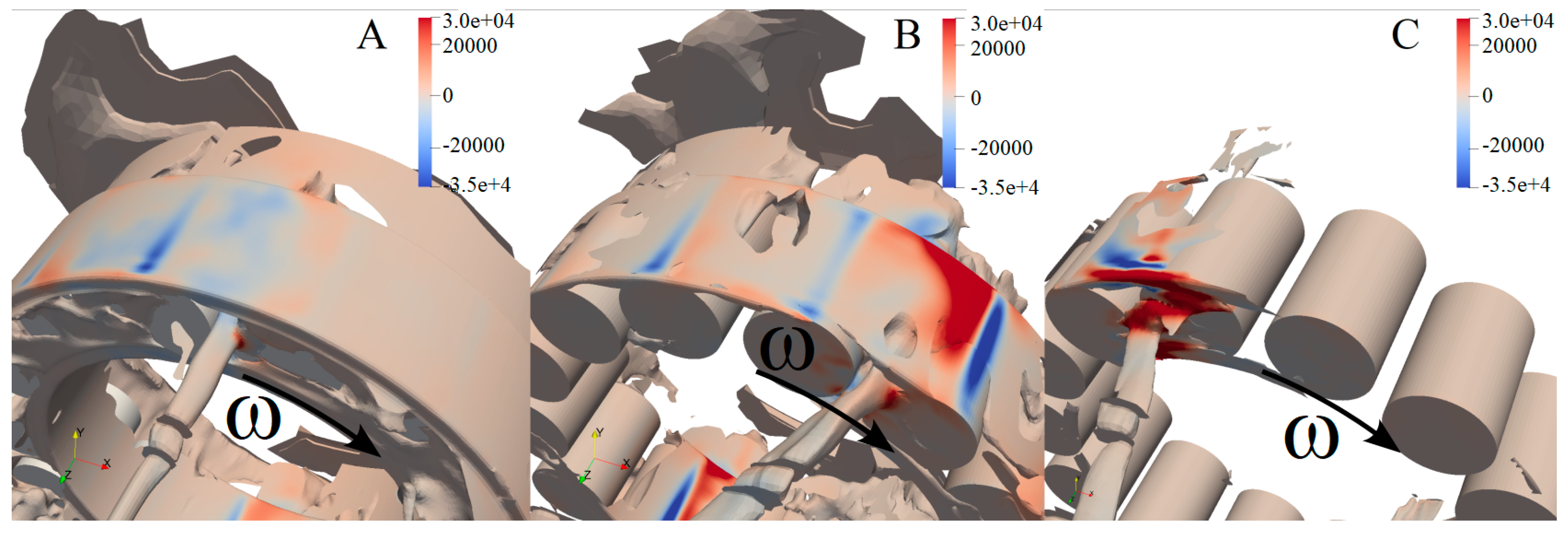
Despite this general consideration, from
Figure 9, it could be clearly observed how the different oil injection directions significantly affect the bearing flooding. The normal direction (
Figure 10A) seems to be the most effective ensuring the highest oil penetration. The oil jet velocity, in fact, is of a higher order of magnitude with respect to the rolling element speed and this fact allows the oil to easily penetrate between the rollers. Moreover, the typical pressures steps of the convergent–divergent can be observed (Bullet 1
Figure 10A).
The 100° configuration (
Figure 10C), with the oil jet oriented in opposition to the cage tangential speed, is not effective at all, and the bearing is not properly lubricated due to the high impact pressures (Bullet 3
Figure 10C). The 80° configuration (
Figure 10B) is better than the 100° one. However, despite the tangential speeds of the jet and the cage having the same orientation, the inclination of the jet implies that the penetration area (namely the area normal to the jet between two rollers) is reduced. Moreover, having the jet at a higher speed with respect to the rollers, the impact foresees a backflow that, in turn, causes a slight overpressure (Bullet 2 in
Figure 10B) that partially limits the oil penetration capability. From these analyses, the 90° configuration is the most effective one. This is confirmed by the streamlines (
Figure 11).
Finally, the lubricant is removed from the gearbox through two holes on the bottom surface. The lubricant flows through the pipes to the reservoir, where the pump picks it up and sends it to the nozzles.
The optimality of the perpendicular (90°) configuration is confirmed by the volumetric flowrate in the axial cross section of the bearing: while the two nozzles provide a total flux of 7.82 L/min, the cross-section flowrates result are 7.44 (90°), 4.83 (100°) and less than 0.5 L/min (80°).
6. Conclusions
The goal of the present paper was to validate the lubricant system design of a special test-rig designed for RCF tests in the framework of a wider project.
To ensure the reliability of the RCF tests, the lubricant supply should be ensured. This condition is particularly difficult to assess, especially in regard to the bearings.
Considering that the oil injection could be affected by the turbulence of the air inside the gearbox, we decided to simulate not only the bearing but the entire test rig. This is still an engineering challenge. The simulation was possible thanks to the GRAMC method for the mesh handling combined with a proper partitioning of the domain and the adoption of arbitrary mesh interfaces.
The simulations took approximately one week to reach the regime condition. The analyses of the gear mating regions have proved the actual oil injection system to be adequate. The study of the bearing nozzle orientation has allowed the selection of the best angle of incidence that maximizes the bearing lubrication.


