Article

Influence of the Distribution of Pits on the Friction and Wear Performance of Textured Rolling Bearings under Starved Lubrication

1
School of Mechanical Engineering and Automation, Northeastern University, Shenyang 110819, China
2
Equipment Reliability Institute, Shenyang University of Chemical Technology, Shenyang 110142, China
3
China Construction Industrial & Engineering Group Co., Ltd., Nanjing 210023, China
*
Author to whom correspondence should be addressed.
Lubricants 2023, 11(5), 197; https://doi.org/10.3390/lubricants11050197
Submission received: 1 March 2023 / Revised: 15 April 2023 / Accepted: 27 April 2023 / Published: 28 April 2023
(This article belongs to the Special Issue Friction and Wear of Rolling-Element Bearings)

Abstract

:
Most of the published documents on the friction and wear properties of textured contact surfaces with partially distributed units (e.g., dots, grooves) are focused on sliding tribo-pairs or journal bearings. To study the friction and wear performance of rolling bearings with different distributions of pits, several patterns were introduced: OS-1/4 (Outside, 1/4 of raceway), OS-1/2 (Outside, 1/2 of raceway), OS-3/4 (Outside, 3/4 of raceway), IS-1/4 (Inside, 1/4 of raceway), IS-1/2 (Inside, 1/2 of raceway), IS-3/4 (Inside, 3/4 of raceway), TS (Two sides, 2/3 of raceway), FT (fully textured) and SR (Smooth reference), with two circumferential interval angles (CFIAs, 1.5° and 2.0°). The dimensions of the pits are the same in all patterns (diameter of 300 μm and depth of 15 μm), which were only prepared on the raceways of the shaft washers of 81107 bearings (nylon cages) using the laser marking method. All bearings were tested under 4000 N, 250 RPM and starved lubrication using a vertical universal wear test rig. Their mass losses and worn raceways were measured and observed. Their surface equivalent stresses were also analyzed and compared. The obtained results show that the influence of different distributions of pits on the tribological properties of rolling bearings is significant. The friction-reducing and anti-wear performance of TS is acceptable, whether the CFIA is 1.5° or 2.0°. A fully textured pattern cannot provide the best tribological properties and its behavior even becomes worse when the CFIA is 2.0°. In this work, when the CFIA is 1.5°, the friction-reducing and anti-wear performance of OS-1/4 is the best among all patterns. Using a smooth reference as a benchmark for comparison, its friction-reducing and anti-wear performance can be enhanced by 60.46% and 16.05%, respectively. The results of this work will be an important reference for the optimal design of the “washers-cage-rollers” contact system for rolling bearings.

Graphical Abstract

1. Introduction

The friction and wear properties of rolling/sliding/sliding-rolling tribo-pairs largely depend on the surface features (e.g., roughness, waveness, toughness and topography) [1], type of contact (e.g., point-to-surface and line-to-surface) [2,3], lubrication regime (e.g., dry wear, boundary lubrication, mixed lubrication and elastohydrodynamic lubrication) [4,5,6], loads (varied or fixed) [7,8], lubricant (e.g., mineral oil, full synthetic oil, water, solid lubricants and 2D materials coatings) as well as materials [9,10,11]. To prolong the service life and improve the reliability of machines, it is very important to enhance the tribological performance of the tribo-pairs involved.
Among all the above-mentioned, only surface features and materials can be customized to meet specific conditions. Through fabricating periodically distributed macro-/micro/multi-scale units (e.g., pillars, pits, grooves and grids) on the contact surfaces, fully or locally, laser surface texture (LST) provides us with a feasible, flexible and economic way to tune the tribological properties and wettability of inter-surfaces [12,13,14,15,16]. Most importantly, there is no need to add any external element. So far, most of the publicly available documents on the partially distributed texture units or local-textured patterns are focused on sliding contact surfaces or journal bearings [17,18,19,20,21,22,23,24,25,26,27]. Tala-Ighil N. et al. researched the influence of textures on contact performance (e.g., the thickness of oil-film, oil-film pressure and oil-film flow in the axial direction) and found that they can be enhanced by choosing a suitable texture unit and entire or partial distribution on the target surface [28]. Rahmani R. et al. outlined a method to calculate the global-optimum design parameters for partially textured sliding surfaces with rectangular and triangular features. They found that when the textured area is between 2/3 and 3/4 of the whole contact surface, the optimal tribological behavior can be obtained [29].
Thrust roller bearings (TRBs) are typically applied to withstand huge axial force and restrict the axial movement of shafts in mechanical devices. TRBs were also chosen to research the effect of different texture units on the friction and wear properties of rolling bearings (RBs) due to their separability and easy processability. Rosenkranz A. et al. prepared dots on the washers of cylindrical roller thrust bearings (CRTB, 81212, SAE 52100). The periodicity of dots was 6.5 μm and their depth was 1 μm. Finally, an 83% reduction in the mass loss of textured bearing was obtained compared with the loss of the non-textured bearing [30]. Long R.S. et al. studied the tribological behavior of rolling bearings (81107TN, nylon cages) with bionic texture units (e.g., dimples, grooves and bionic veins) under different lubricating conditions [4,7,8,31,32,33,34,35,36]. However, research on the tribological properties of partially textured rolling bearings under starved lubrication has not been reported yet.
Therefore, based on previous works [4,7,31,32,33,34], eight patterns with fully or locally distributed pits were prepared on the contact surfaces of the shaft washers of TRBs (81107TN, nylon cages). The dimensions of the pits were the same in all patterns. All bearings were tested under 4000 N, 250 RPM and starved lubrication using a vertical universal wear test rig [35,37]. Their friction torques, wear losses and worn raceways (shaft washers) were measured and characterized. The surface equivalent stresses on the contact surfaces and the influence of fully/locally distributed patterns on the friction and wear properties of rolling bearings under the above conditions were also analyzed and discussed. The obtained data and conclusions will be an important reference for the design of the “washers-cage-rollers” contact system for rolling bearings.

2. Materials, Modeling and Setup

2.1. Materials

The structure and load parameters of the bearings (81107TN, YFB, Changzhou, China) can be found in Table 1 [32]. The metal components, i.e., housing washer, shaft washer and rollers, were manufactured with SAE52100 steel. Their surface hardness is 60 ± 1 HRC. The cage is made of black nylon (PA66) [38].
During wear tests, the purchased HX7 (5W-30) lubricating oil was used. The dynamic viscosity of the oil is 14.45 mm2/s and its density at 30 °C is 0.8678 kgL−1.

2.2. Modeling

Based on the locations of pits and the width of the textured area, eight patterns were introduced: OS-1/4 (Outside, 1/4 of raceway), OS-1/2 (Outside, 1/2 of raceway), OS-3/4 (Outside, 3/4 of raceway), IS-1/4 (Inside, 1/4 of raceway), IS-1/2 (Inside, 1/2 of raceway), IS-3/4 (Inside, 3/4 of raceway), TS (Two-sides, 2/3 of raceway) and FT (fully textured) (see Figure 1). The diameter of each pit is 300 μm. The depth of each pit is 15 μm. The aspect ratio of pits is 1. The minimum distance between the center points of two pits in the radius direction is 0.89 mm. The above four parameters are the same in all patterns. The circumferential interval angle (CFIA) is 1.5° or 2.0°. In addition, one smooth group was also tested as a reference and named SR. The area density of one pattern is the percentage of the total area of pits to the area of the raceway (see Table 2).
To minimize the effect of uncertain factors on the results, each pattern was repeatedly tested using three new bearings. Therefore, the 81107TN bearings consumed is 3 × (9 + 8) = 51.

2.3. Experimental Setup and Methodology

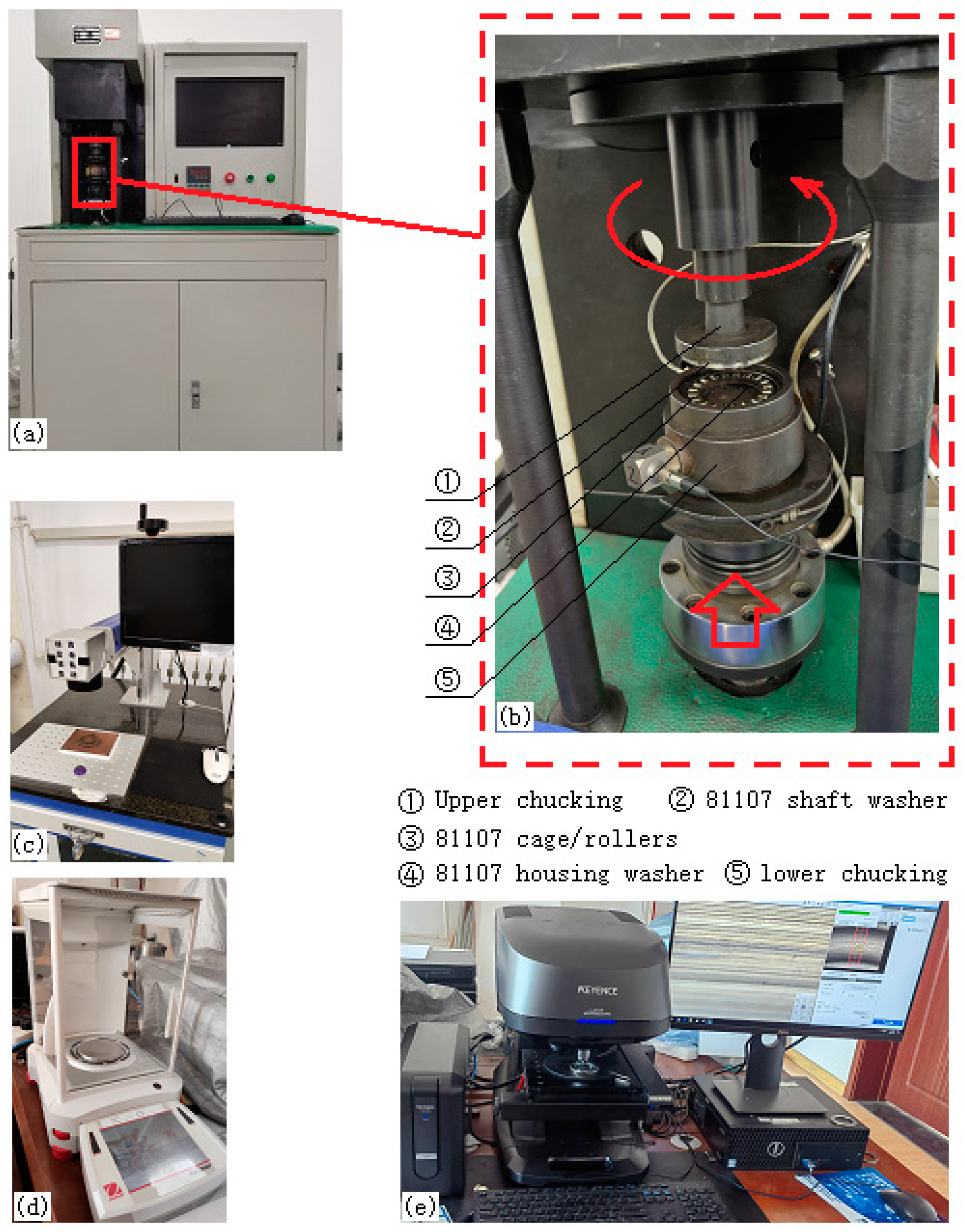
The PL100-30W laser marking machine was chosen to prepare pits on the shaft washer. The processing parameters are shown in Table 3. Before laser marking, the antirust oil on the target surfaces was swept away in advance. As shown in Figure 2a,b, the MMW-1A vertical universal wear test rig was selected to study the friction and wear performance of TRBs using customized chucking [35].
During wear tests, the applied vertical force was fixed and equal to 4000 N. The rotating speed was 250 revolutions per minute (RPM). Every bearing was tested for 18,000 s (5 h). Prior to each test, the textured shaft washer was polished to remove the micro-bulges caused by the laser pulse using waterproof abrasive papers (from 800 meshes to 2000 meshes). When the surface roughness met the requirement, the textured washer was cleaned using an ultrasonic cleaner (≥15 min) and dried with hot air. Then, a drop of lubricating oil was dripped on the textured contact surface. The mass of the added oil is 12.1 mg, which is the arithmetic mean of twenty measurements and can be adjusted by an operator with the help of an EX225D balance. The precision of the electronic analytical balance is 0.1 mg, and its readability is 0.01 mg. Using repeated trials, the combination of 4000 N, 250 RPM and 12.1 mg was chosen. In this condition, the bearings can finish the wear tests and their variations in the coefficients of friction (COF) will be evident and significant. Note that no lubricating oil was provided in wear tests to ensure that all bearings were running under starved lubrication.
When one test was finished, a VK-1050 profilometer was used to observe the contact surface first. The work mode of the profilometer is white + laser confocal. Then, the whole bearing was placed in an ultrasonic cleaner (≥15 min) prior to mass measurement and dried with hot air. The mass loss of the shaft washer can be obtained by subtracting its mass after the test from its mass before the test.

2.4. Simulation Modeling and Setup

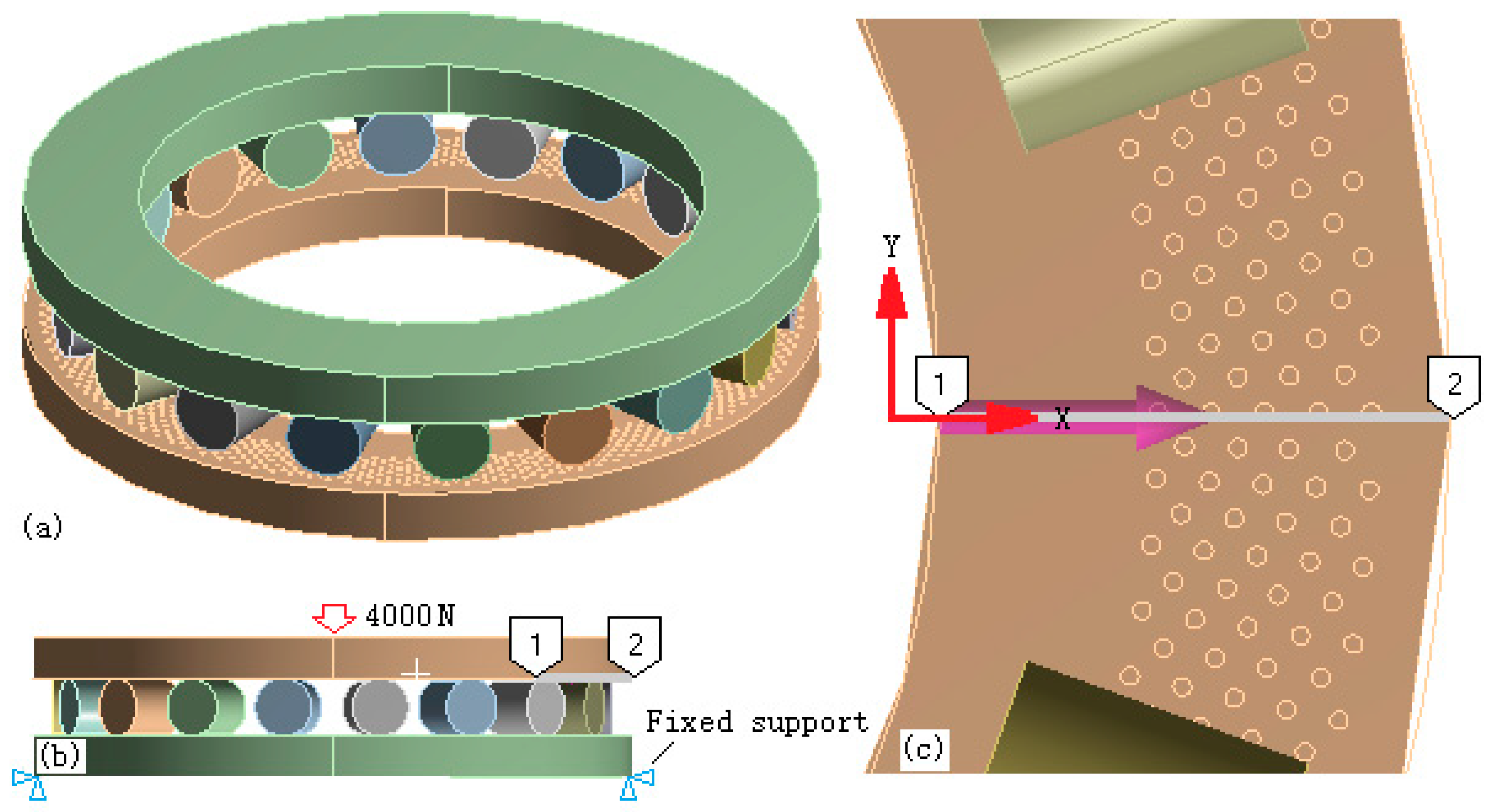
The surface stresses of CRTBs with different patterns were studied using an ANSYS Workbench. The created model can be found in Figure 3. The materials of washers and rollers are steel, whose elastic modulus and Poisson’s ratio are 210 GPa and 0.30, respectively.
As shown in Figure 3b, the bottom of the housing washer was applied as a fixed support. A vertical force (4000 N) was added to the upper surface of the shaft washer. The mesh type and solver were selected using the program. The element size was set to 0.6 mm during meshing. As a result, the number of elements in the textured models is about 222,600–266,600, which is much higher than that of the smooth reference at 71,600.
In addition, as shown in Figure 3c, a path was introduced to compare the surface stress difference among all patterns easily. The path is set 0.02 mm below the contact surface of the shaft washer to ensure that it is below all the pits. The direction is from point 1 to point 2 along the X-axis.

3. Results of Experiments and Simulations

3.1. COFs

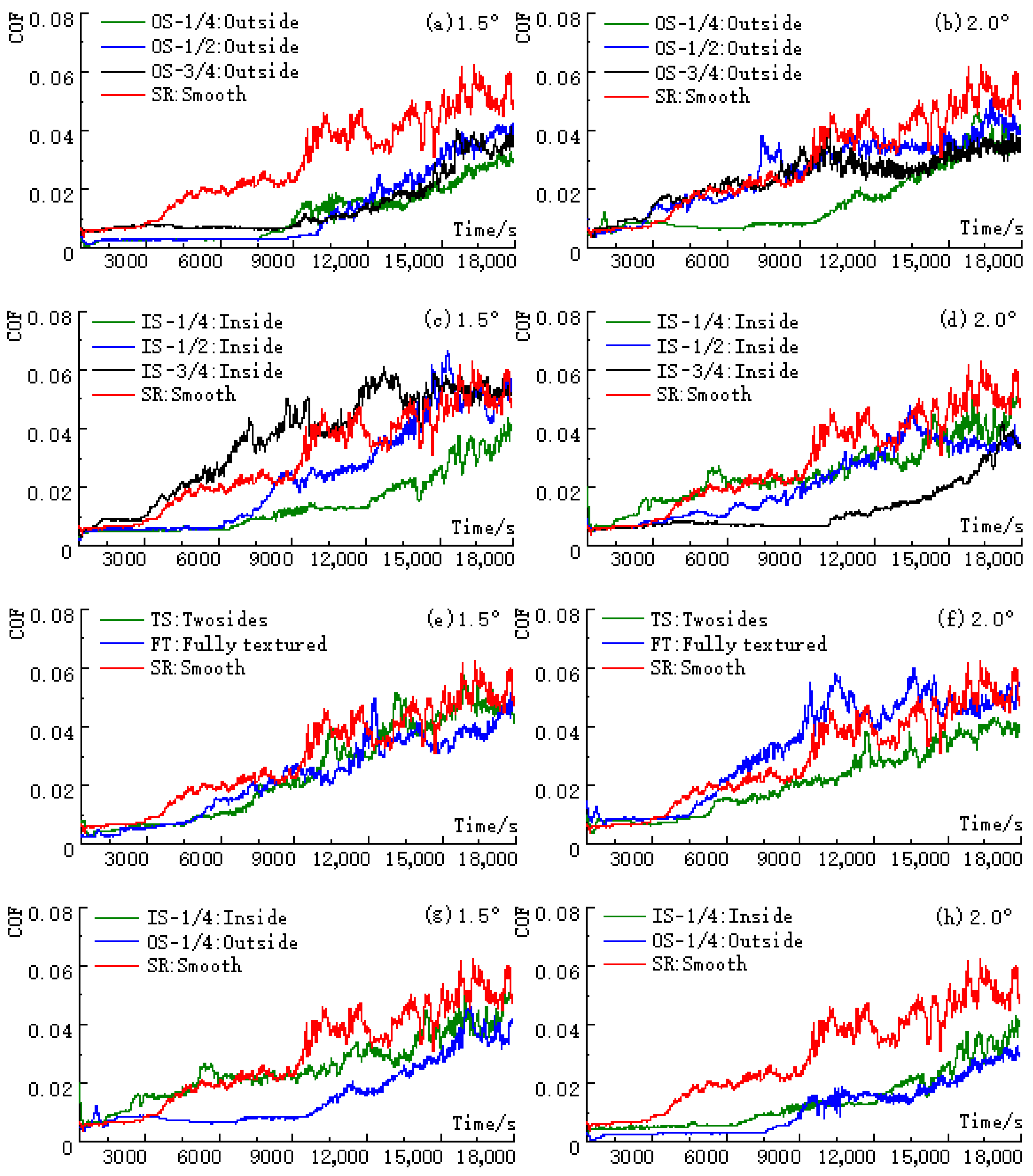
The COF curves for the different patterns under starved lubrication are shown in Figure 4. It should be noted that every point on one curve in Figure 4 is the arithmetic mean of the values from three bearings at the same sampling point. Evidently, there are two periods in all the curves in the figure: the stable-running period and the fast-rising period, whether textured or smooth. When the CFIA is 1.5°, the stable-running periods in the COF curves tend to be longer.
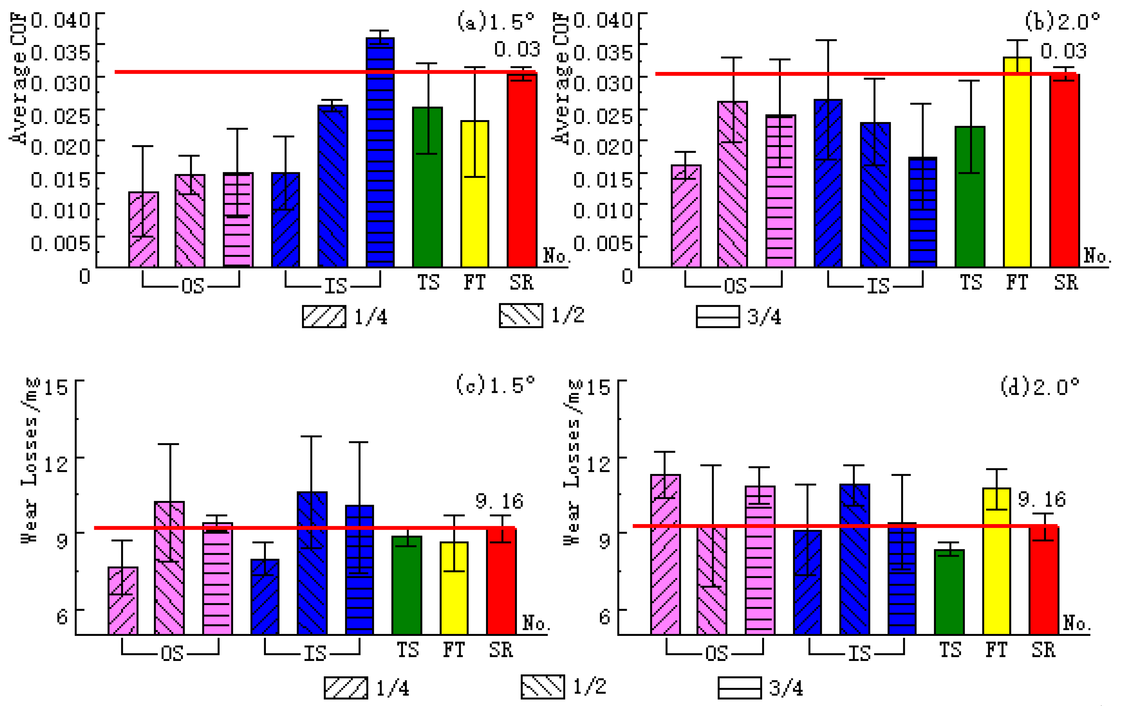
The average COF for the different patterns is compared in Figure 5a,b. Apparently, the values for most textured groups are smaller than the value for the SR, except IS-3/4 (1.5°) and FT (2.0°), indicating the significant friction-reducing performance of textured bearings under 4000 N, 250 RPM and starved lubrication.

3.2. Mass Losses and Worn Raceways

The wear losses in the eight patterns and two CFIAs are compared in Figure 5c,d. It should be noted that the value of one pattern in the figure is the arithmetic mean of the losses from three tests. It is easy to find that when the CFIA gets larger, from 1.5° to 2.0°, the anti-wear properties of the eight patterns are quite different. Specifically, when the CFIA is 1.5°, the mass losses in OS-1/4, IS-1/4, TS and FT are less than the loss in the SR (9.16 mg). Among the four groups, the mass loss in OS-1/4 is the least (see Figure 5c). The mass losses in OS-1/2 and IS-1/2 are quite larger than that in the SR. While the CFIA is 2.0°, as shown in Figure 5d, the mass loss in TS is the smallest. The wear loss in IS-1/4 is also smaller than the loss in the SR. The losses in OS-1/4, OS-3/4, IS-1/2 and FT are much larger than the value in the SR.
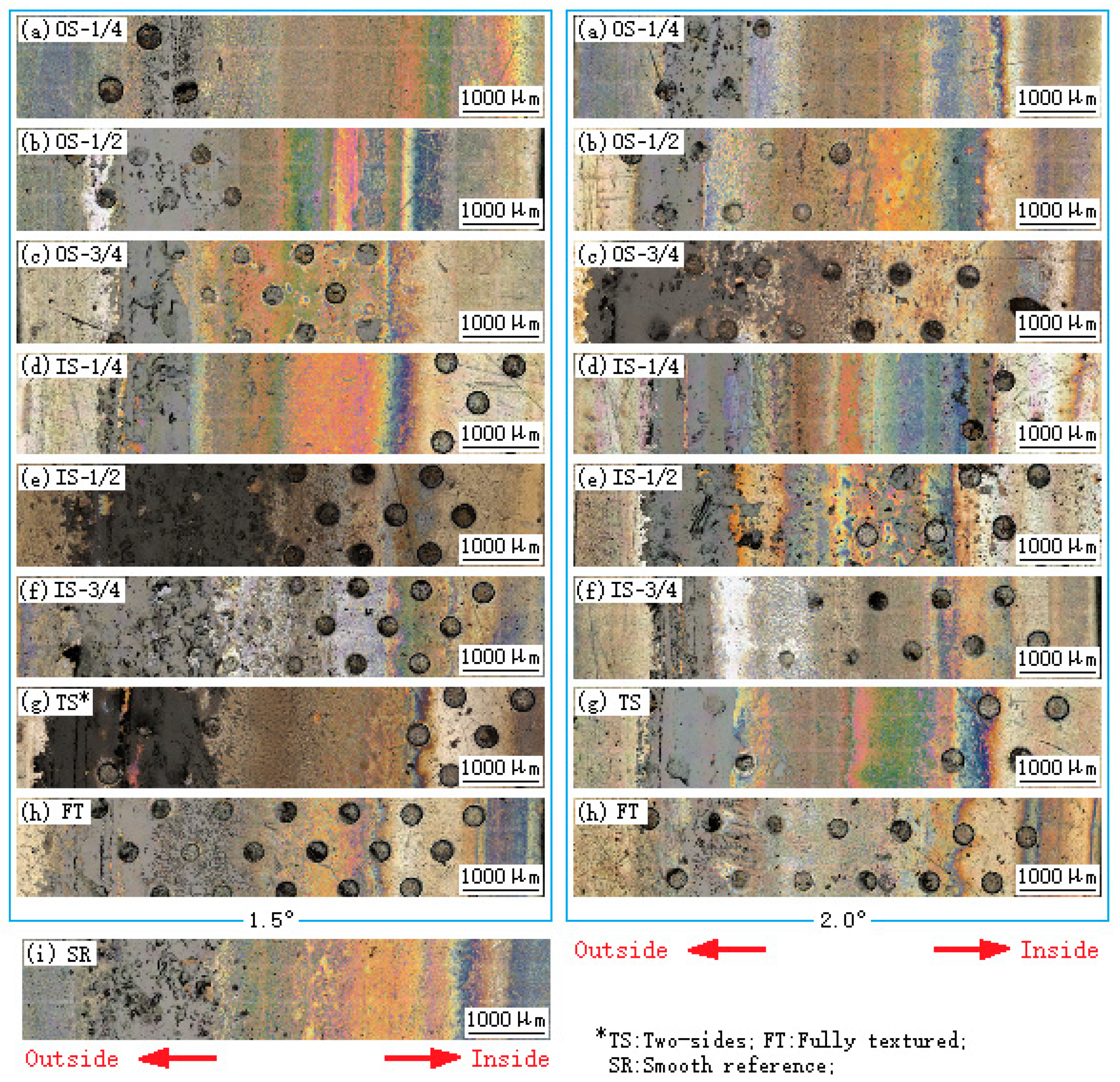
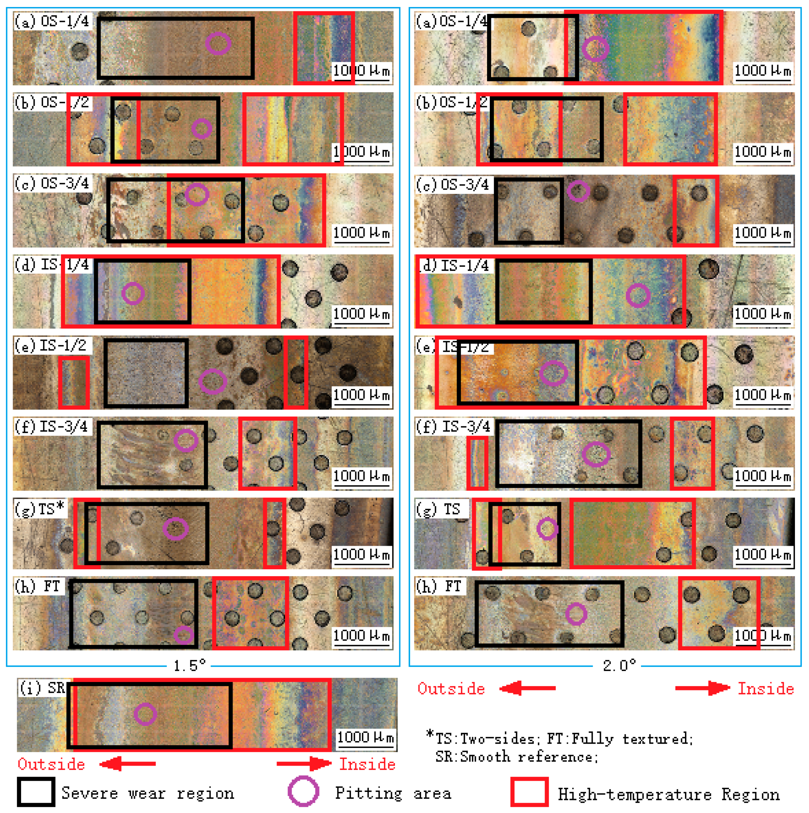
The unwashed worn raceways of eight patterns and two CFIAs are compared in Figure 6. Apparently, black film forms on the outside of the contact surface in every pattern, especially IS-1/2(1.5°), IS-3/4(1.5°), TS(1.5°) and OS-3/4(2.0°). The film was identified in Ref. [32] using an IS10 infrared spectrometer, and the spectra of PA66 were clearly found. The cleaned worn raceways of the eight patterns and two CFIAs are compared in Figure 7. As shown in the figure, high-temperature regions can be found on the worn surfaces. When the CFIA is 2.0°, the high-temperature marks are much more serious than the conditions when the CFIA is 1.5°. By comparing the raceways in Figure 7, the failure mode for all CRTBs in this work can be inferred as serious abrasive wear and obvious fatigue pitting.

3.3. Surface Equivalent Stresses

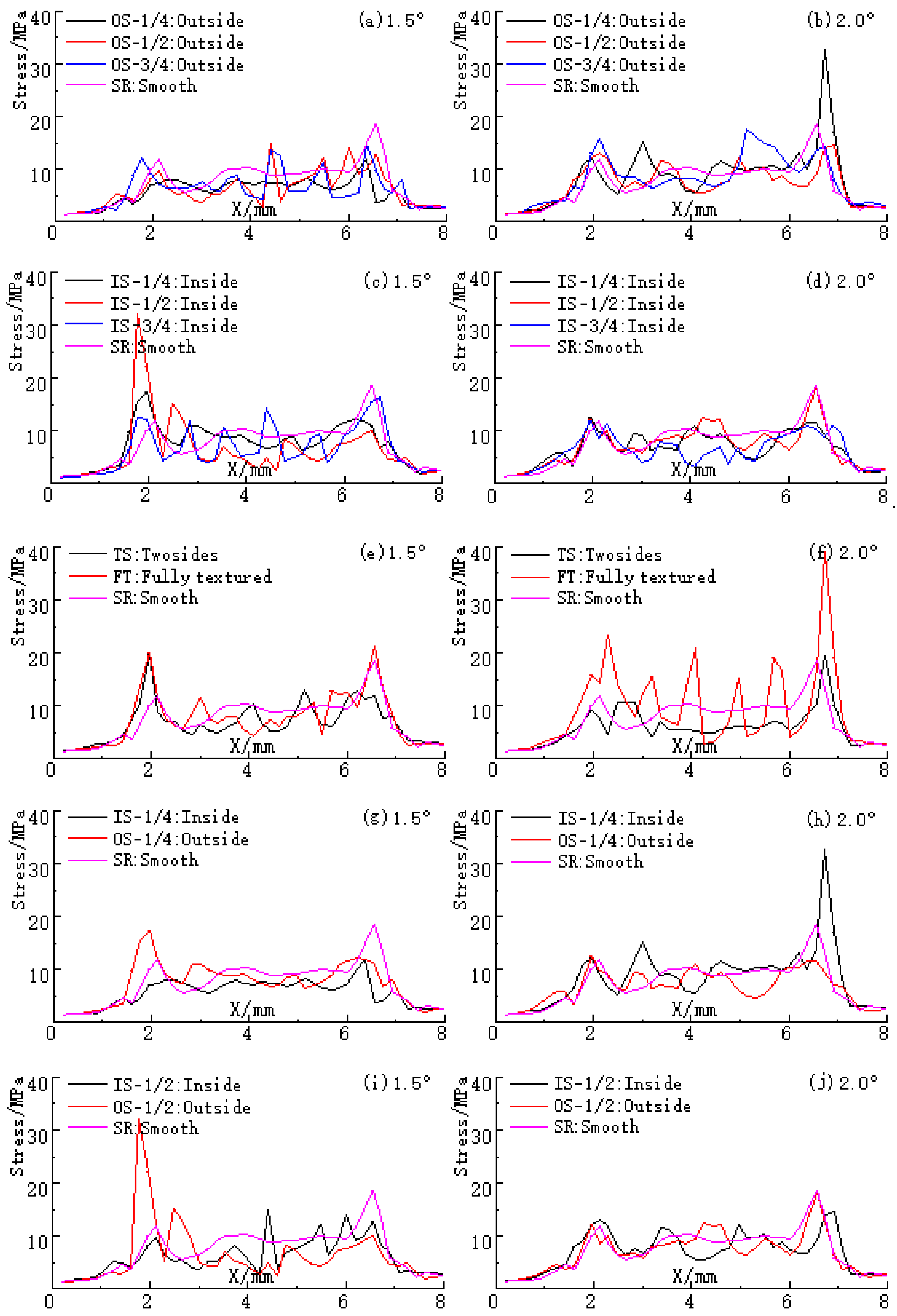
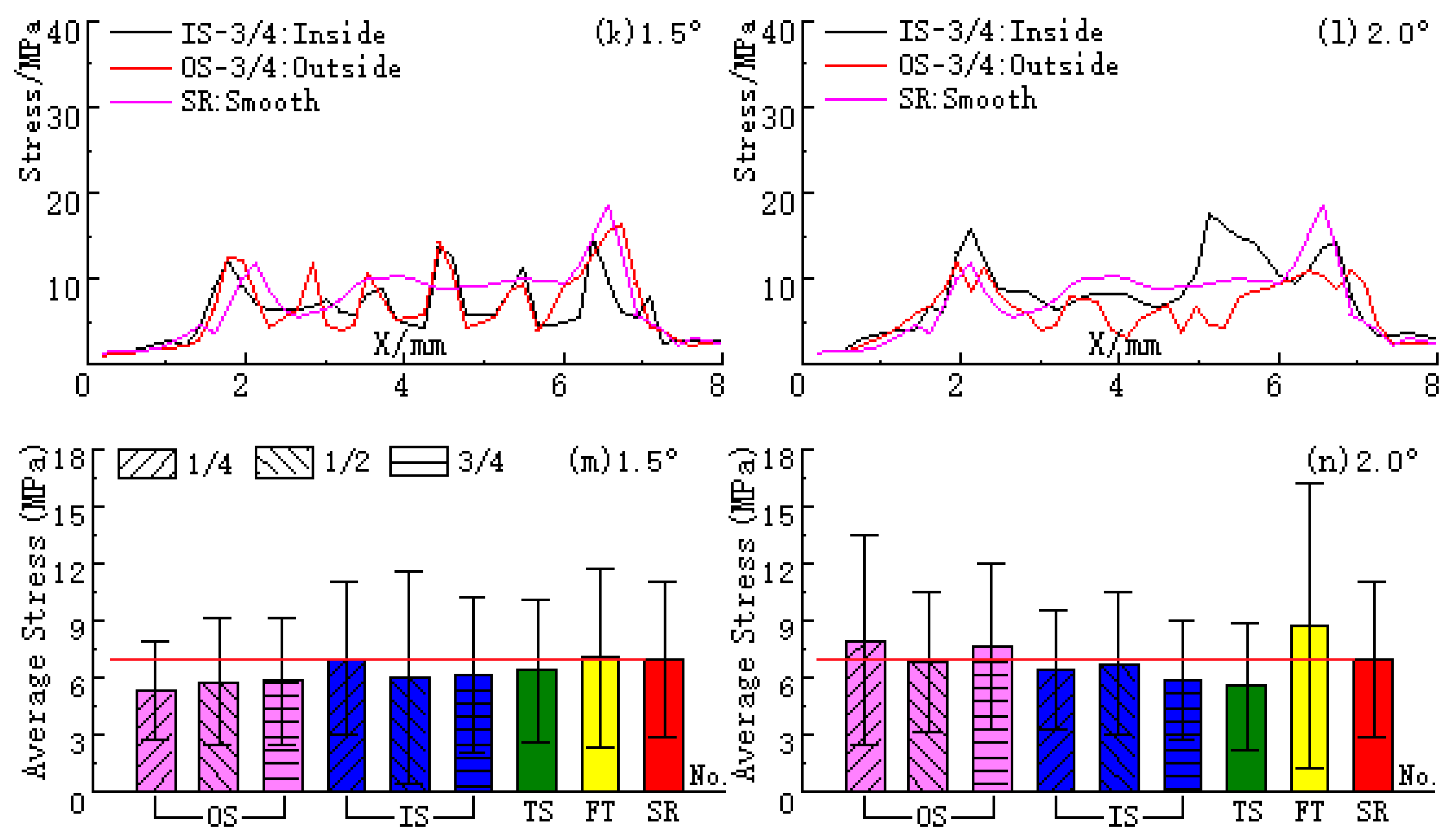
The surface equivalent stress curves for the different patterns (along the paths) and their averages are compared in Figure 8. Owing to the “edge crushing effect” between the rollers and the shaft washers, two apparent stress peaks can be found on all curves, whether textured or smooth. As for each curve in the figure, the stress peak near the endpoint on the path is obviously larger than the peak near the start point on the path. Different from the results in Ref. [32], when the CFIA is 1.5°, the average surface equivalent stresses in most partially textured patterns are smaller than the stresses in the SR and FT, except IS-1/4 (see Figure 8m).
As shown in Figure 8n, when the CFIA is 2.0°, the average surface equivalent stresses in OS-1/4, OS-3/4 and FT are significantly larger than the stress in the SR [32]. The surface equivalent stress in OS-1/2 is very close to the value in the SR.
Therefore, the effect of partially textured patterns on the surface equivalent stresses is significant. The average stress in FT is close to the stress in the SR when the CFIA is 1.5° and even is larger than the value in the SR as the CFIA is 2.0°.

4. Discussion

4.1. Effect of CFIAs on the Friction and Wear Properties

When the CFIA is 1.5°, as shown in Figure 5a,c, the average COF for most patterns were greatly reduced, especially OS-1/4, OS-1/2, OS-3/4 and IS-1/4. The value for IS-3/4 is the only one higher than that of the smooth reference. Using the data from the SR as a benchmark for comparison, the anti-wear properties of OS-1/4 and IS-/1/4 are greatly enhanced. The wear resistance of FT is also improved, but the wear behavior of OS-1/2, OS-3/4, IS-1/2 and IS-3/4 become worse.
When the CFIA is 2.0°, the average COF for almost all patterns was significantly reduced too, except FT. The anti-wear properties of most patterns are worse than the wear resistance of SR, except IS-1/4 and TS (see Figure 5b,d). FT is the only one with a higher average COF and greater mass loss. The wear resistance of TS is the only group that has been significantly improved. By comparing Figure 5d and Figure 8n, it is easy to find that when the CFIA is 2.0°, the wear losses of the bearings have the same trend as their surface stresses. However, this phenomenon is not obvious when the CFIA is 1.5° (see Figure 5c and Figure 8m).
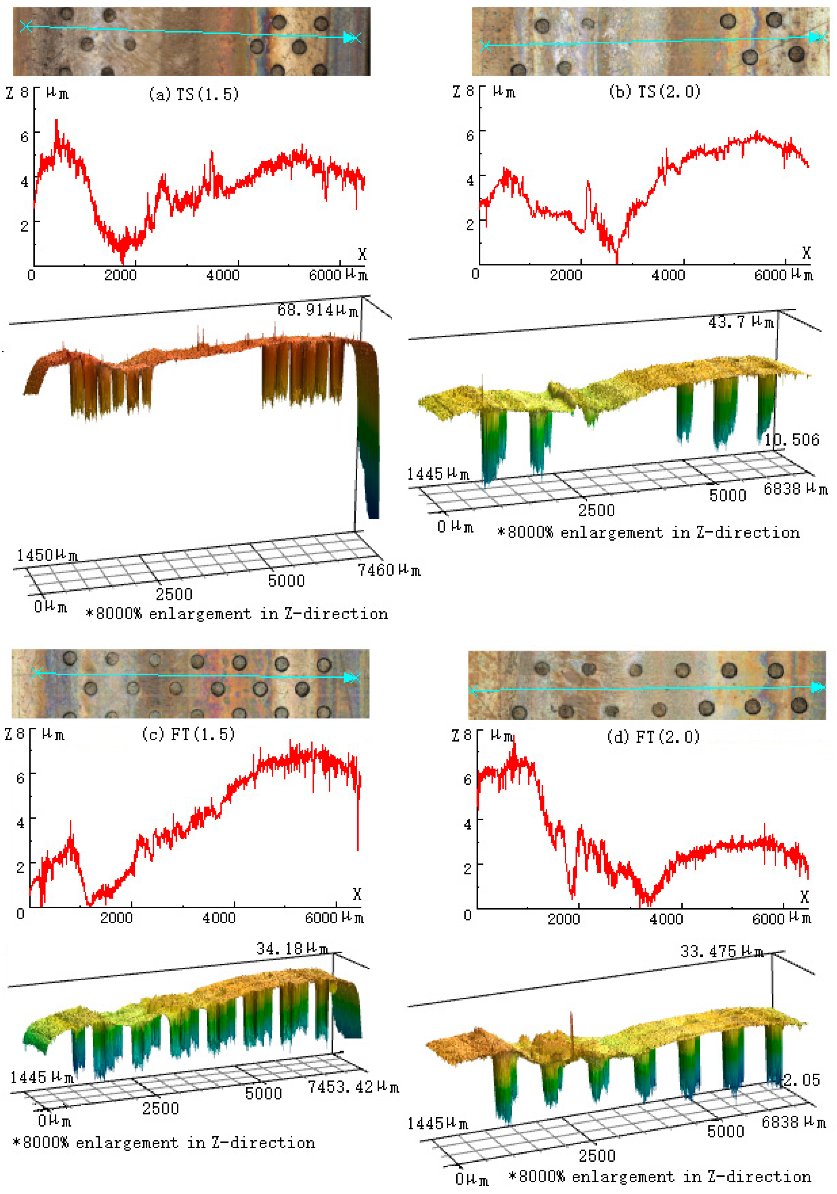
Therefore, in summary, the influence of CFIAs on the friction and wear properties of rolling bearings is significant under 4000 N, 250 RPM and starved lubrication. The COF variations in the textured patterns are even completely opposite when the CFIA is different (see Figure 4c,d,i–l). This is because CFIAs determine the count of pits on the textured raceways, i.e., area densities. When the CFIA is 2.0°, the area densities of the eight patterns are quite smaller than the densities when the CFIA is 1.5° (see Table 2). Higher area density means a larger capacity to hold debris (both metal and nylon) and store more lubricating oil in the “washers-cage-rollers” contact system in the earlier stage, which is crucial to reduce the average COF and mass loss of rolling bearings. This is the main reason for the tribological difference in FT between the two CFIAs. However, higher area density also indicates a reduced effective contact area (ECA) and more pits. If the ECA is too small, the fatigue pitting and spalling of the material will become serious, which will significantly deteriorate the tribological behavior of bearings and cause severe abrasive wear. Obviously, a turning point exists for the CFIA, which has not been obtained in this work yet and needs to be further studied. Among all patterns, when the CFIA is 1.5°, the tribological performance of OS-1/4 is the best. Using the data from the SR as a benchmark for comparison, its friction-reducing performance is improved by 60.46% and its wear resistance is enhanced by 16.05%.

4.2. Effect of the Location of Pits on Friction and Wear Properties

When the CFIA is 1.5°, the average COF for the outside-distributed groups (OS-1/4, OS-1/2 and OS-3/4) is significantly smaller than the value for the SR (see Figure 5a). When the CFIA is 2.0°, the average COF for OS-1/2 and OS-3/4 is much higher than that for OS-1/4, and their curves in Figure 4b are entangled with the curve of the SR first and then gradually become lower. When the pits are on the inside of raceways, as shown in Figure 4c,d, the COF curves of the three patterns are the opposite: The curve of IS-1/4 is the lowest in Figure 4c but the highest in Figure 4d. The curve of IS-3/4 is the highest in Figure 4c but the lowest in Figure 4d. With regard to the fully textured (FT) and two sides (TS) patterns, their curves are entangled with that of the smooth group when the CFIA is 1.5° (see Figure 4e) but are more easily distinguished when the CFIA is 2.0° (see Figure 4f).
To reveal the effect of the widths of textured regions on the tribological properties of rolling bearings, W is introduced and defined as the percentage of the width of the textured region to the width of the whole contact surface. When W is 25%, the COF curves of IS-1/4 and OS-1/4 are apparently lower than the curve of the SR and mix together when the CFIA is 2.0°. When the CFIA is 1.5°, the curve of IS-1/4 is entangled with that of the smooth reference instead (see Figure 4g).
When W is 50%, OS-1/2 and IS-1/2 can be distinguished clearly in Figure 4i, but they mix together in Figure 4j. When W is 75%, the curves of the two patterns are the opposite (see Figure 4k,l): the curve of OS-3/4 is the lowest in Figure 4k, but it is much higher than that of IS-3/4 in Figure 4l. The curve of IS-3/4 is the highest in Figure 4k but the lowest in Figure 4l.
Using the mass loss in the SR as a benchmark for comparison, as shown in Figure 5c, when the CFIA is 1.5°, the wear resistance of OS-1/4 is the best in all patterns. The anti-wear performance of IS-1/4 is also greatly improved. The wear losses in OS-1/2 and IS-1/2 are quite high. When the CFIA is 2.0°, the anti-wear performance of TS is the best. The wear resistance of IS-1/4 is also improved. The wear behavior of OS-1/4, OS-3/4, IS-1/2 and FT is worse than the result for the SR (see Figure 5d). TS can provide acceptable friction-reducing and anti-wear properties, whether the CFIA is 1.5° or 2.0°.

4.3. Influence Mechanism for Partially Distributed Patterns on the Friction and Wear Properties of Rolling Bearings under Starved Lubrication

The effect of the partially distributed patterns on the tribological performance of rolling bearings under the conditions in this work (4000 N, 250 RPM and starved lubrication) can be summarized as the following:
(1)
When a rolling bearing keeps rotating under lubricated conditions, the lubricant will move on the raceways of washers under the driving of centrifugal force, whether textured or smooth [39]. When there is no oil added during the whole test under starved lubrication, the bearing will gradually enter the dry wear stage with the gradual consumption of lubricant. The storage capacities of the pits in textured patterns can cause “secondary lubrication” of the contact surfaces, which is the reason why the friction drag in almost all textured patterns becomes more reduced than the result for the SR, especially when the CFIA is 1.5°. During the transition process from boundary lubrication to the dry condition, nylon powder is gradually generated for the gradual direct contact between metal rollers and the holes of a cage. Owing to the “centrifugal throwing effect” during fast rotating, wear debris (both metal and nylon) transfers onto the raceway, which will cause a transition from two-body friction to three-body friction. As a result, the friction drag and temperature in the “washers-cage-rollers” contact system increase gradually, and the rollers may even become stuck by debris [4,31,32,33,34,35,36]. Due to the collection and storage capacity of pits, the metal debris and nylon powder retained on the textured contact surface is quite less than the conditions of smooth bearings. However, the nylon transferring film is still gradually formed for high-contact flash temperature and concentrated on the positions, as shown in Figure 6. Finally, the friction-reducing performance of the bearing will gradually decrease but its anti-wear may be enhanced because of the well-tribological and self-lubricating properties of nylon (see Figure 4 and Figure 5).
(2)
Partially distributed patterns may decrease the surface equivalent stresses of textured contact surfaces, especially the two stress peaks [32]. This will bring more advantages than disadvantages for the tribological behavior of rolling bearings and is also the reason why the friction and wear properties of TS are improved, whether the CFIA is 1.5° or 2.0°. Although the inside-distributed pits can collect and store wear debris, a sudden change from the textured region to the smooth region can seriously break the transfer of debris. This is the reason why the tribological properties of IS-3/4 are so poor when the CFIA is 1.5°. This is also the reason for the excellent tribological performance of outside-distributed patterns (OS-1/4, OS-1/2 and OS-3/4) when the CFIA is 1.5°.
(3)
CFIA directly affects the area density of textured patterns and the number of pits. A larger area density and more pits mean a large capacity of the textured contact surface. Consequently, the stored oil in the earlier stage and the debris storage capacity in the later stage will be significantly enhanced, which is why, when the CFIA is 1.5°, the tribological behavior of bearings is obviously better than that when the CFIA is 2.0°. However, more pits also imply a reduced ECA. Based on the classical Coulomb formula, the friction will increase, and the COF is also bound to increase. The fatigue peeling of material along the edges of pits will become serious for the stress concentration in this condition (see Figure 9). Eventually, the metal debris generated may leave the “washers-cage-rollers” contact system or be melted with the nylon transferring film. What is left in the system will cause deterioration in the tribological performance of rolling bearings, as observed for IS-1/2 and IS-3/4 [4,7,8,31,32,33,34,35,36].
(4)
Different from the conditions of partially textured patterns, the “secondary lubrication effect” of the fully textured group is the strongest, but it also has the problem of seriously hindering the transfer of debris and powder. This is the reason why the friction and wear properties of OS-1/4(1.5°), IS-1/4 and TS are superior to FT.
In fact, the real tribological behavior of entirely/partially textured rolling bearings is very complicated and unpredictable. It is mainly dependent on the comprehensive effect of the following factors: area density of textured contact surface (i.e., effective contact area), the effective capacity of pits (i.e., number of pits), surface equivalent stresses, “secondary lubrication”, the “edge crushing effect”, loads, lubricant, nylon film, etc.

5. Conclusions

According to the obtained tribological data under starved lubrication, the following conclusions were obtained and listed as follows:
(1)
The influence of different distributions of pits on the tribological performance of rolling bearings is obvious and great. The tribological behavior of a fully textured pattern cannot be satisfactory and even becomes worse when the CFIA is 2.0°. The friction and wear properties of TS are acceptable, whether the CFIA is 1.5° or 2.0°.
(2)
When the CFIA is 1.5°, the tribological properties of most textured groups are enhanced compared with those when the CFIA is 2.0°. So, a turning point exists for the CFIA, which needs to be further studied in the future.
(3)
Compared with the surface stress data for the full-textured patterns, the stresses in the partially textured patterns are significantly reduced. When the CFIA is 2°, the surface stresses and wear losses in all patterns have the same trend. When the CFIA is 1.5°, this phenomenon is not obvious.
(4)
In this work, when the CFIA is 1.5°, the tribological performance of OS-1/4 is outstanding. Using the data from the non-textured group (SR) as a benchmark for comparison, its friction-reducing performance is improved by 60.46%, and its wear resistance is enhanced by 16.05%.

Author Contributions

Conceptualization, R.L.; methodology, R.L.; software, M.W.; validation, M.W.; formal analysis, Y.C. and C.Z.; investigation, Y.C. and C.Z.; resources, Z.J.; data curation, C.Z.; writing—original draft preparation, Y.C.; writing—review and editing, R.L.; visualization, Y.C.; supervision, Z.J.; project administration, Z.J.; funding acquisition, R.L. All authors have read and agreed to the published version of the manuscript.

Funding

The research was funded by the National Key R & D Program of China (No. 2019YFB2004400), the National Natural Science Foundation of China (No. 52275156), the National Natural Science Foundation of China Young Scientist Fund (No. 51901141), the Natural Science Foundation of Liaoning province (No. 2023-MS-234) and the Scientific Research Fund of Liaoning Provincial Education Department (No. LJKMZ20220800).

Institutional Review Board Statement

Not applicable.

Informed Consent Statement

Not applicable.

Data Availability Statement

The data presented in this study are available on request from the corresponding author.

Conflicts of Interest

The authors declare no conflict of interest.

References

  1. König, F.; Rosenkranz, A.; Grützmacher, P.G.; Mücklich, F.; Jacobs, G. Effect of single- and multi-scale surface patterns on the frictional performance of journal bearings—A numerical study. Tribol. Int. 2020, 143, 106041. [Google Scholar] [CrossRef]
  2. Marian, M.; Grützmacher, P.; Rosenkranz, A.; Tremmel, S.; Mücklich, F.; Wartzack, S. Designing surface textures for EHL point-contacts-Transient 3D simulations, meta-modeling and experimental validation. Tribol. Int. 2019, 137, 152–163. [Google Scholar] [CrossRef]
  3. Boidi, G.; Tertuliano, I.S.; Profito, F.J.; De Rossi, W.; Machado, I.F. Effect of laser surface texturing on friction behaviour in elastohydrodynamically lubricated point contacts under different sliding-rolling conditions. Tribol. Int. 2020, 149, 105613. [Google Scholar] [CrossRef]
  4. Zhao, C.; Long, R.S.; Zhang, Y.M.; Wang, Y.B.; Wang, Y.Y. Influence of characteristic parameters on the tribological properties of vein-bionic textured cylindrical roller thrust bearings. Tribol. Int. 2022, 175, 107861. [Google Scholar] [CrossRef]
  5. Gropper, D.; Wang, L.; Harvey, T.J. Hydrodynamic lubrication of textured surfaces: A review of modeling techniques and key findings. Tribol. Int. 2016, 94, 509–529. [Google Scholar] [CrossRef]
  6. Kovalchenko, A.; Ajayi, O.; Erdemir, A.; Fenske, G.; Etsion, I. The effect of laser surface texturing on transitions in lubrication regimes during unidirectional sliding contact. Tribol. Int. 2005, 38, 219–225. [Google Scholar] [CrossRef]
  7. Long, R.S.; Ma, Q.; Jin, Z.H.; Zhang, Y.M.; Han, H.; Sun, S.N.; Du, X.Y. Tribological behavior of dimples textured rolling bearings under stepped load and starved lubrication. Ind. Lubr. Tribol. 2022, 74, 876–883. [Google Scholar] [CrossRef]
  8. Long, R.S.; Li, M.H.; Jin, Z.H.; Zhang, Y.M.; Han, H. Tribological behavior of pits textured multi-rollers sliding-rolling tribo-pair under periodic varied load and dry wear. Adv. Mech. Eng. 2022, 14, 16878132221092520. [Google Scholar] [CrossRef]
  9. Rosenkranz, A.; Costa, H.L.; Baykara, M.Z.; Martini, A. Synergetic effects of surface texturing and solid lubricants to tailor friction and wear—A review. Tribol. Int. 2021, 155, 106792. [Google Scholar] [CrossRef]
  10. Grützmacher, P.G.; Suarez, S.; Tolosa, A.; Gachot, C.; Song, G.C.; Wang, B.; Presser, V.; Muücklich, F.; Anasori, B.; Rosenkranz, A. Superior Wear-Resistance of Ti3C2Tx Multilayer Coatings. ACS Nano 2021, 15, 8216–8224. [Google Scholar]
  11. Marian, M.; Feile, K.; Rothammer, B.; Bartz, M.; Wartzack, S.; Seynstahl, A.; Tremmel, S.; Krauß, S.; Merle, B.; Böhm, T.; et al. Ti3C2Tx solid lubricant coatings in rolling bearings with remarkable performance beyond state-of-the-art materials. Appl. Mater. Today 2021, 25, 101202. [Google Scholar] [CrossRef]
  12. Grützmacher, P.G.; Rosenkranz, A.; Szurdak, A.; Grüber, M.; Gachot, C.; Hirt, G.; Mücklich, F. Multi-scale surface patterning-an approach to control friction and lubricant migration in lubricated systems. Ind. Lubr. Tribol. 2019, 71, 1007–1016. [Google Scholar] [CrossRef]
  13. Rosenkranz, A.; Grützmacher, P.G.; Murzyn, K.; Mathieu, C.; Mücklich, F. Multi-scale surface patterning to tune friction under mixed lubricated conditions. Appl. Nanosci. 2021, 11, 751–762. [Google Scholar] [CrossRef]
  14. Gachot, C.; Rosenkranz, A.; Hsu, S.M.; Costa, H.L. A critical assessment of surface texturing for friction and wear improvement. Wear 2017, 372–373, 21–41. [Google Scholar] [CrossRef]
  15. Rosenkranz, A.; Grützmacher, P.G.; Gachot, C.; Costa, H.L. Surface Texturing in Machine Elements-A Critical Discussion for Rolling and Sliding Contacts. Adv. Eng. Mater. 2019, 21, 1900194. [Google Scholar] [CrossRef]
  16. Khaskhoussi, A.; Risitano, G.; Calabrese, L.; D’Andrea, D. Investigation of the Wettability Properties of Different Textured Lead/Lead-Free Bronze Coatings. Lubricants 2022, 10, 82. [Google Scholar] [CrossRef]
  17. Etsion, I.; Sher, E. Improving fuel efficiency with laser surface textured piston rings. Tribol. Int. 2009, 42, 542–547. [Google Scholar] [CrossRef]
  18. Senatore, A.; Risitano, G.; Scappaticci, L.; D’Andrea, D. Investigation of the Tribological Properties of Different Textured Lead Bronze Coatings under Severe Load Conditions. Lubricants 2021, 9, 34. [Google Scholar] [CrossRef]
  19. Ali, S.; Kurniawan, R.; Moran, X.; Ahmed, F.; Danish, M.; Aslantas, K. Effect of Micro-Dimple Geometry on the Tribological Characteristics of Textured Surfaces. Lubricants 2022, 10, 328. [Google Scholar] [CrossRef]
  20. Tang, H.S.; Ren, Y.; Xiang, J.W.; Anil, K. Evaluation and optimization of axial piston pump textured slipper bearings with spherical dimples based on hybrid genetic algorithm. Proc. Inst. Mech. Eng. Part J Eng. Tribol. 2021, 235, 1719–1741. [Google Scholar] [CrossRef]
  21. Prasad, K.N.; Syed, I.; Subbu, S.K. Laser dimple texturing—Applications, process, challenges, and recent developments: A review. Austral. J. Mech. Eng. 2019, 20, 316–331. [Google Scholar] [CrossRef]
  22. Galda, L.; Sep, J.; Olszewski, A.; Zochowski, T. Experimental investigation into surface texture effect on journal bearings performance. Tribol. Int. 2019, 136, 372–384. [Google Scholar] [CrossRef]
  23. Vlădescu, S.C.; Fowell, M.; Mattsson, L.; Reddyhoff, T. The effects of laser surface texture applied to internal combustion engine journal bearing shells-An experimental study. Tribol. Int. 2019, 134, 317–327. [Google Scholar] [CrossRef]
  24. Rodrigues, G.W.; Bittencourt, M.L. Surface virtual texturing of the journal bearings of a three-cylinder ethanol engine. Ind. Lubr. Tribol. 2020, 72, 1059–1073. [Google Scholar] [CrossRef]
  25. Jin, J.; Chen, X.C.; Fu, Y.Y.; Chang, Y.H. Optimal design of the slip-texture on a journal-bearing surface. Ind. Lubr. Tribol. 2021, 73, 230–237. [Google Scholar] [CrossRef]
  26. Sharma, S.; Sharma, A.; Jamwal, G.; Awasthi, R.K. The effect of v-shape protruded and dimple textured on the load-carrying capacity and coefficient of friction of hydrodynamic journal bearing: A comparative numerical study. Proc. Inst. Mech. Eng. Part J Eng. Tribol. 2021, 235, 997–1011. [Google Scholar] [CrossRef]
  27. Li, J.N.; Han, K.; Chen, W.G.; Tang, X.J.; Wang, Q. An improved TEHL analysis of textured roller bearings consider various texture parameters and slip. Ind. Lubr. Tribol. 2020, 73, 373–380. [Google Scholar] [CrossRef]
  28. Tala-Ighil, N.; Maspeyrot, P.; Fillon, M.; Bounif, A. Effects of surface texture on journal-bearing characteristics under steady-state operating conditions. Proc. Inst. Mech. Eng. Part J Eng. Tribol. 2007, 221, 623–633. [Google Scholar] [CrossRef]
  29. Rahmani, R.; Rahnejat, H. Enhanced performance of optimised partially-textured load bearing surfaces. Tribol. Int. 2018, 117, 272–282. [Google Scholar] [CrossRef]
  30. Rosenkranz, A.; Stratmann, A.; Gachot, C.; Burghardt, G.; Jacobs, G.; Mücklich, F. Improved Wear Behavior of Cylindrical Roller Thrust Bearings by Three-Beam Laser Interference. Adv. Eng. Mater. 2016, 18, 854–862. [Google Scholar] [CrossRef]
  31. Long, R.S.; Zhao, C.; Jin, Z.H.; Zhang, Y.M.; Pan, Z.; Sun, S.N.; Gao, W.H. Tribological Behavior of Dents textured Rolling bearings under Starved Lubrication. Ind. Lubr. Tribol. 2021, 73, 971–979. [Google Scholar] [CrossRef]
  32. Long, R.S.; Shang, Q.Y.; Jin, Z.H.; Zhang, Y.M.; Ju, Z.C.; Li, M.H. Tribological behavior of laser textured rolling bearings under starved lubrication. Ind. Lubr. Tribol. 2022, 74, 453–462. [Google Scholar] [CrossRef]
  33. Long, R.S.; Pan, Z.; Jin, Z.H.; Zhang, Y.M.; Sun, S.N.; Wang, Y.Y.; Wang, Y.B.; Li, M.H. Tribological behavior of grooves textured thrust cylindrical roller bearings under dry wear. Adv. Mech. Eng. 2021, 13, 16878140211067284. [Google Scholar] [CrossRef]
  34. Long, R.S.; Zhao, C.; Zhang, Y.M.; Wang, Y.B.; Wang, Y.Y. Effect of vein-bionic surface textures on the tribological behavior of cylindrical roller thrust bearing under starved lubrication. Sci. Rep. 2021, 11, 21238. [Google Scholar] [CrossRef] [PubMed]
  35. Chen, Y.Z.; Long, R.S.; Jin, Z.H.; Zhao, C.; Wang, M. Research on the Tribological Behavior of Textured Cylindrical Roller Thrust Bearings with Different Distributions of Pits and Nylon Cages under Dry Condition. Lubricants 2023, 11, 154. [Google Scholar] [CrossRef]
  36. Wang, Y.Y.; Zhang, Y.M.; Long, R.S. Influence of Pits on the Tribological Properties and Friction-Induced Vibration Noise of Textured Tapered Roller Bearings. Tribol. T. 2022. [Google Scholar] [CrossRef]
  37. Saeidi, F.; Parlinska-Wojtan, M.; Hoffmann, P.; Wasmer, K. Effects of laser surface texturing on the wear and failure mechanism of grey cast iron reciprocating against steel under starved lubrication conditions. Wear 2017, 386–387, 29–38. [Google Scholar] [CrossRef]
  38. Gao, S.; Han, Q.K.; Zhou, N.N.; Zhang, F.B.; Yang, Z.H.; Chatterton, S.; Pennacchi, P. Dynamic and wear characteristics of self-lubricating bearing cage: Effects of cage pocket shape. Nonlinear Dynam. 2022, 110, 177–200. [Google Scholar] [CrossRef]
  39. Grützmacher, P.G.; Rosenkranz, A.; Rammacher, S.; Gachot, C.; Mücklich, F. The influence of centrifugal forces on friction and wear in rotational sliding. Tribol. Int. 2017, 116, 256–263. [Google Scholar] [CrossRef]
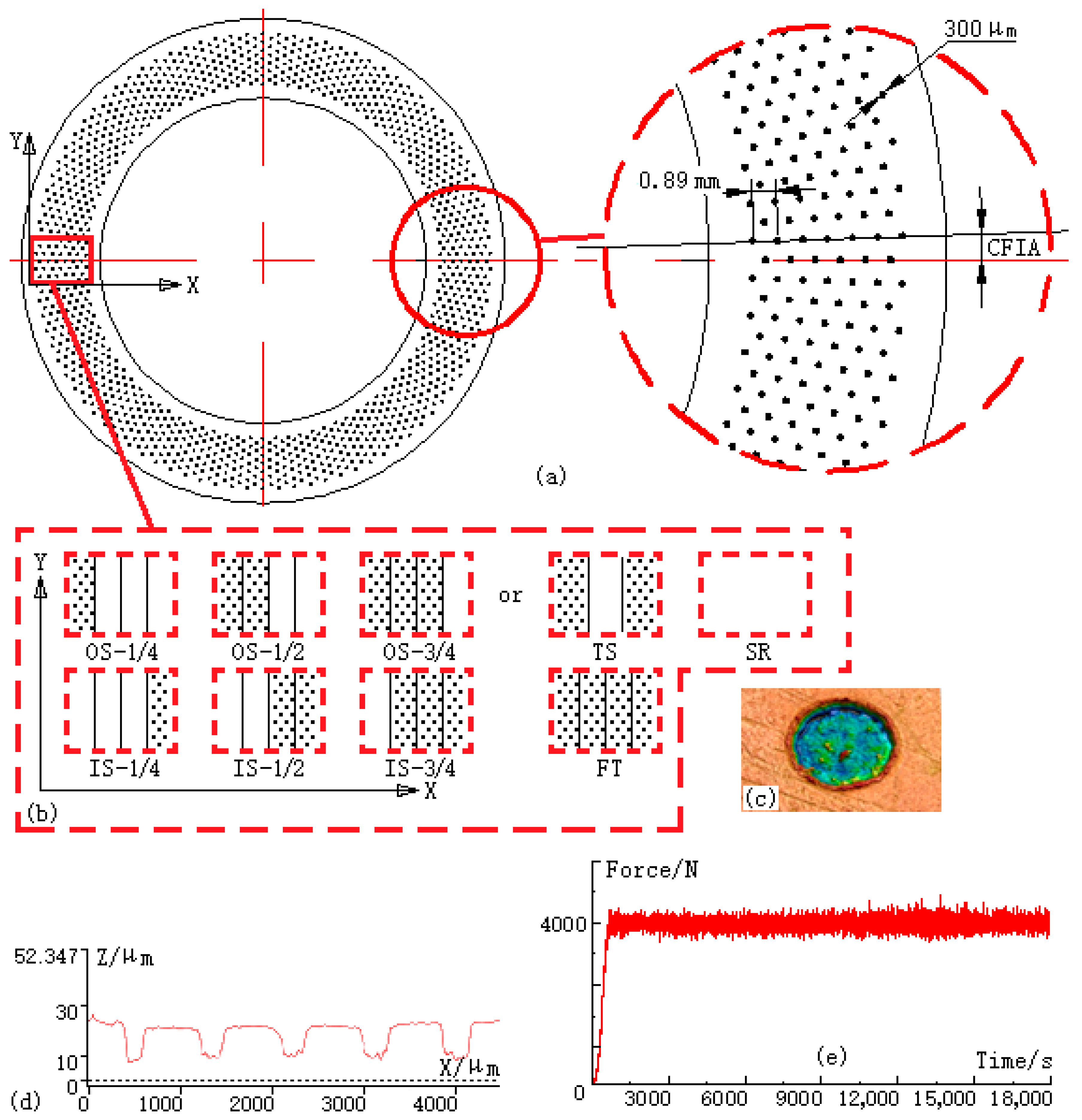
Figure 1. Model showing pits on the textured shaft washer, the characteristics of pits fabricated using the laser marking method and the applied force during wear tests. (a) Parameters of pits; (b) eight distributions of pits; (c) three-dimensional figure of one pit; (d) section profile of pits; and (e) the applied force in tests.
Lubricants 11 00197 g001
Figure 2. Images showing the equipment used in this work. (a) Wear test rig; (b) 81107 chucking; (c) laser marking machine; (d) electric analytical balance; and (e) 3D profilometer.
Lubricants 11 00197 g002
Figure 3. Model of the 81107 bearings created using ANSYS Workbench, boundary conditions and path setting. (a) FE model of the 81107 bearings; (b) boundary conditions; and (c) the enlarged view of the path (The X coordinate axis follows the radial direction of the bearing, and its positive direction is consistent with the direction of the path. The Y-axis follows the circumferential direction of the bearing).
Lubricants 11 00197 g003
Figure 4. COF curves showing the different patterns under starved lubrication. (a) outside groups, 1.5°; (b) outside groups, 2.0°; (c) inside groups, 1.5°; (d) inside groups, 2.0°; (e) TS and FT, 1.5°; (f) TS and FT, 2.0°; (g) IS-1/4 and OS-1/4, 1.5°; (h) IS-1/4 and OS-1/4, 2.0°; (i) IS-1/2 and OS-1/2, 1.5°; (j) IS-1/2 and OS-1/2, 2.0°; (k) IS-3/4 and OS-3/4, 1.5°; (l) IS-3/4 and OS-3/4, 2.0°.
Lubricants 11 00197 g004aLubricants 11 00197 g004b
Figure 5. The average COFs and wear losses in the different patterns under starved lubrication. (a) Average COFs of different groups, 1.5°; (b) Average COFs of different groups, 2.0°; (c) Wear losses of different groups, 1.5°; (d) Wear losses of different groups, 2.0°.
Lubricants 11 00197 g005
Figure 6. The unwashed worn raceways of the different patterns under starved lubrication. (a) OS-1/4; (b) OS-1/2; (c) OS-3/4; (d) IS-1/4; (e) IS-1/2; (f) IS-3/4; (g) TS (Two-sides); (h) FT (Fully textured); (i) SR (Smooth reference).
Lubricants 11 00197 g006
Figure 7. The cleaned worn raceways of the different patterns. (a) OS-1/4; (b) OS-1/2; (c) OS-3/4; (d) IS-1/4; (e) IS-1/2; (f) IS-3/4; (g) TS (Two-sides); (h) FT (Fully textured); (i) SR (Smooth reference).
Lubricants 11 00197 g007
Figure 8. Surface equivalent stresses in the eight patterns and two CFIAs. (a) outside groups, 1.5°; (b) outside groups, 2.0°; (c) inside groups, 1.5°; (d) inside groups, 2.0°; (e) TS and FT, 1.5°; (f) TS and FT, 2.0°; (g) IS-1/4 and OS-1/4, 1.5°; (h) IS-1/4 and OS-1/4, 2.0°; (i) IS-1/2 and OS-1/2, 1.5°; (j) IS-1/2 and OS-1/2, 2.0°; (k) IS-3/4 and OS-3/4, 1.5°; (l) IS-3/4 and OS-3/4, 2.0°; (m) Average stresses of different groups, 1.5°; (n) Average stresses of different groups, 2.0°.
Lubricants 11 00197 g008aLubricants 11 00197 g008b
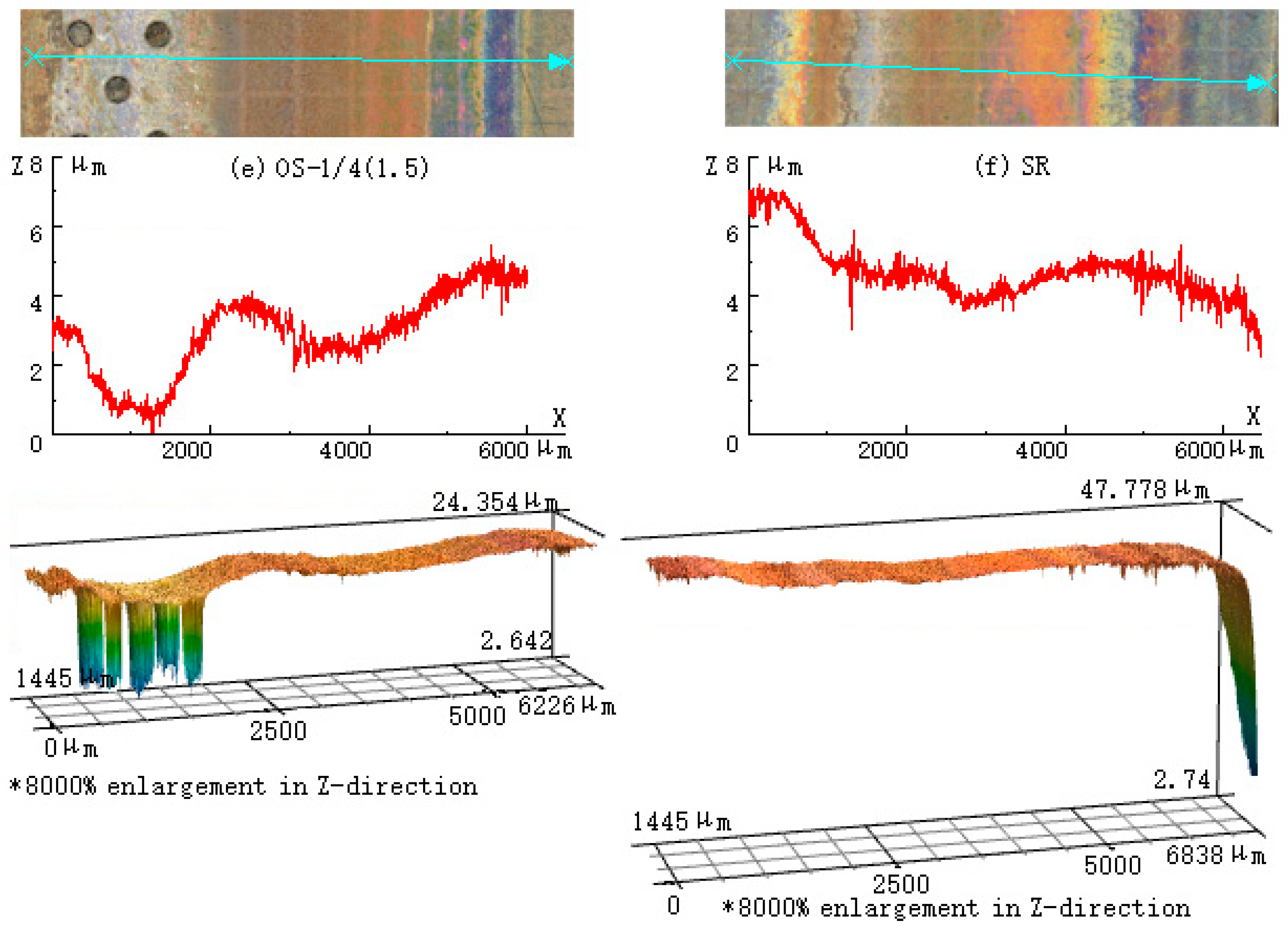
Figure 9. Three-dimensional worn surfaces on several patterns. (a) TS(1.5); (b) TS(2.0); (c) FT(1.5); (d) FT(2.0); (e) OS-1/4(1.5); and (f) SR.
Lubricants 11 00197 g009aLubricants 11 00197 g009b
Table 1. Structure and load parameters of the 81107TN bearings.
PartDimensionValue
Shaft washerOuter diameter (mm)Φ 52
Diameter of inner hole (mm)Φ 35
Height (mm)3.5
Housing washerOuter diameter (mm)Φ 52
Diameter of inner hole (mm)Φ 37
Height (mm)3.5
RollersHeight (mm)5
Diameter (mm)Φ 5
Number18
Basic rated static/dynamic load (N)101,000/39,000
Ultimate fatigue load (N)9500
Table 2. Patterns, CFIAs and area densities of the 81107TN groups.
Group No.PatternCFIA (°)Area Density (%)
OS-1/4Lubricants 11 00197 i0011.5/2.02.19/1.64
OS-1/2Lubricants 11 00197 i0021.5/2.04.38/3.29
OS-3/4Lubricants 11 00197 i0031.5/2.06.57/4.93
IS-1/4Lubricants 11 00197 i0041.5/2.02.19/1.64
IS-1/2Lubricants 11 00197 i0051.5/2.04.38/3.29
IS-3/4Lubricants 11 00197 i0061.5/2.06.57/4.93
TSLubricants 11 00197 i0071.5/2.05.80/3.29
FTLubricants 11 00197 i0081.5/2.09.49/8.76
SR---
Table 3. Processing parameters of the laser marking machine.
ItemValue
Wave length (μm)1064
Scanning speed (mm/s)100
Maximum laser power (W)30
Laser power output ratio (%)30
Frequency (Hz)72
Disclaimer/Publisher’s Note: The statements, opinions and data contained in all publications are solely those of the individual author(s) and contributor(s) and not of MDPI and/or the editor(s). MDPI and/or the editor(s) disclaim responsibility for any injury to people or property resulting from any ideas, methods, instructions or products referred to in the content.