Article

Thermo-Hydrodynamic Lubrication Analysis of Slipper Pair Considering Wear Profile

1
School of Mechanical Engineering, Hunan University of Science and Technology, Xiangtan 411201, China
2
School of Automotive Engineering, Hunan Electrical College of Technology, Xiangtan 411101, China
3
Hunan Provincial Key Laboratory of Mechanical Equipment Health Maintenance, Hunan University of Science and Technology, Xiangtan 411201, China
*
Author to whom correspondence should be addressed.
Lubricants 2023, 11(5), 190; https://doi.org/10.3390/lubricants11050190
Submission received: 1 March 2023 / Revised: 15 April 2023 / Accepted: 19 April 2023 / Published: 25 April 2023

Abstract

:
The profile of sealing land is a sensitive factor affecting the thermo-hydrodynamic lubrication characteristics of the slipper pair. In this paper, the non-uniform wear of the running surface under the slipper was presented and defined as the boundary condition. Based on the finite volume method and the successive over-relaxation iteration method, a discrete numerical model coupled with the temperature, pressure, and thickness of the oil film was constructed. The Newton and sequential circulation methods were used to solve the coupling equations. The influence of the wear profile on the film thickness, sliding attitude, and leakage were discussed. The analyzed results show that the control of the wear on the outer side of sealing land and the contour vertex position, and the avoidance of the wear on the inner side of sealing land could improve the thermo-hydrodynamic lubrication performance of the slipper pair.

1. Introduction

The slipper pair is one of the most important friction pairs in swash plate axial piston pumps or motors. Its structure schematic diagram is shown in Figure 1, which includes the swash plate, slipper, and ball joint. The high-pressure oil flows into the sealing land through the damping hole and pocket to produce a lubricating film. Because of the machining error, running wear, and elastic thermal deformation, the non-uniform gap in the range of the running surface always appears. Under hydrodynamic lubrication, the hydraulic bearing force offered by the bottom of the slipper could balance the clamping force from the displacement chamber, and the anti-roll moment could counteract the centrifugal torque, the bottom friction torque, and the friction torque from the ball joint when the slipper is rotating. If the force and torques could not be balanced, the profile of the sealing land will have eccentric wear. The wear of height is close to the thickness of the oil film and is considered a sensitive parameter affecting the performance of hydrodynamics. The determination of the wear parameters of the sealing land is the basis to reveal the thermo-hydrodynamic lubrication performance and could provide a theoretical basis for forming the appropriate wear profile through microstructure optimization, for example, by adding some relief groove on the running surface.
Although the structure of the slippers seems simple, its operation mechanism is complex. A lot of researchers focus on the boundary of velocity, pressure, and temperature as well as the profile of the running surface [1,2,3,4,5,6]. Based on the ideal rigid sealing land, the dynamic characteristics of the sliding pair were theoretically and experimentally analyzed by Harris [7]; there is a significant difference between the results of experimental and theoretical under the condition of large tilt angles [8]. Kakoullis revealed that the tilting clearance should be non-uniform, especially since the micro convex structure can produce a wedge convergence effect and improve the operation stability, and the influence of the running surface profile on the dynamic characteristics of the slipper was qualitatively studied [9]. The leakage and friction power loss of the slipper in the rigid and elastic states were analyzed in [10]; the elastic deformation was present as a factor in forming uneven gaps. Two possible elastic deformation profiles were assumed by Manring, and the influence of elastic deformation on the pressure distribution, leakage, and bearing capacity of the slipper pair under low-speed conditions was researched [11]. Based on the simulation tool CASPAR [12,13], thermal deformation along with elastic deformation of the slipper bottom surface and swash plate bottom surface were taken into account, and the influence of axial fretting on oil film thickness was analyzed [14]. The profile of the running surface in the slipper pair after running was measured by Liu [15], and found to be slightly convex; the lubrication characteristics of the slipper pair with and without a wear profile were analyzed, and the influence of the wear profile on the minimum oil film thickness, central film thickness, and inclination angle torque was studied. Hooke revealed that the wear is sensitive to operating conditions, and has a very wide range of possible surface after running, ranging in height from less than 0.1 μm to over 10 μm [16]. Ivantysyn presented a simulation approach to output wear profiles using Caspar FSTI [17]. The minimization of oil film thickness and power loss was considered as the optimization objective to obtain the optimal wear profile parameters of the running surface under different working conditions presented in [18]. Xu’s recent research has shown that traditional slippers suffer from serious wear at high rotational speeds, and presents a new integrated slipper retainer mechanism to eliminate slipper wear under severe operating conditions [19].
According to the literature mentioned above, the performance analysis of the slipper pair considering the wear profile is more consistent with engineering practice, which has been agreed upon by scholars. Understanding the thermo-hydrodynamic lubrication characteristic of the slipper pair, considering the wear profile, is the basis of optimizing the micro-structure design of the sealing land. In this paper, according to the characteristics of easy collapse of the outer side and wear of the inner side in the single sealing land slipper, the inner and outer wear profile is considered as the input boundary [20]. In consideration of the mutual coupling relationship between the temperature, pressure, and thickness of the oil film, the mathematical model of the thermo-elastic effect, revolution dynamic pressure effect, and rotation dynamic pressure effect is built to analyze the influence of wear profile on the oil film thickness, sliding attitude, and leakage.

2. System theory

2.1. Definition of the Coordinate System

As shown in Figure 1, the polar coordinate system (R,φ) was constructed, and its origin is located at the center of the circle in the swash plate surface marked as Op, which could describe the revolutionary movement of the slipper. The rectangular coordinate system (x,y) was built, and its origin is located at the center of the ball joint marked as Ob. The x-axis is tangent to the sliding track of the slipper and points to the negative sliding direction, and the y-axis is perpendicular to the sliding track of the slipper center and points to the outside of the swash plate, which can describe the overturning state of the slipper. The cylindrical coordinate system (r,θ,z) was set, and its origin is located in the center of the running surface marked as Os. The z-axis points to the thickness direction of the slipper pair oil film, and the angle θ is positive in the counterclockwise direction and starts from the x-axis, which is used to describe the oil film shape, pressure, and stress distribution.

2.2. Kinematic Analysis

The swash plate inclination is defined as angle β. When the ball joint is rotating around the drive shaft at the angular speed of ω, the radial velocity Vr at a random point M in the running surface could be expressed as
V r = ω s R m cos θ r
where ω s = ω cos β cos 2 φ + sin 2 φ cos 2 β , R s = R 1 + tan 2 β cos 2 φ , R m = r 2 + R s 2 + 2 r R s cos ( θ π 2 ) , θ r = arccos R s sin θ π / 2 R m .
If the revolution angular speed of the slipper was equal to the rotation angular speed [21], the circumferential velocity Vθ at a random point M in the running surface could be expressed as
V θ = ω s R m sin θ r r

2.3. Reynolds Equation

Based on Reynolds’s hypothesis, the conservative expression of the Reynolds equation for incompressible fluid can be described as [22]:
1 r r r h 3 μ p r + r θ h 3 r μ p θ = 6 1 r r r h V r + 6 r θ h V θ + 12 h t
Through the numerical solution, the pressure pi,j at random points in the oil film could be obtained. The physical quantity characterized by the lubrication performance of the slipper pair could be determined, such as the bearing capacity, leakage, friction torque, and power loss et al.

2.4. Non-Uniform Clearance of Oil Film Thickness

The oil film thickness h at random point M in the running surface could be described as
h = h g + Δ h m + Δ h p + Δ h T
where hg is the film thickness of the ideal rigid slipper bottom surface, Δhm is the corrected film thickness caused by the wear, Δhp is the change in film thickness caused by the elastic deformation, and ΔhT is the change in film thickness caused by the thermal deformation, which was presented in detail in [23].
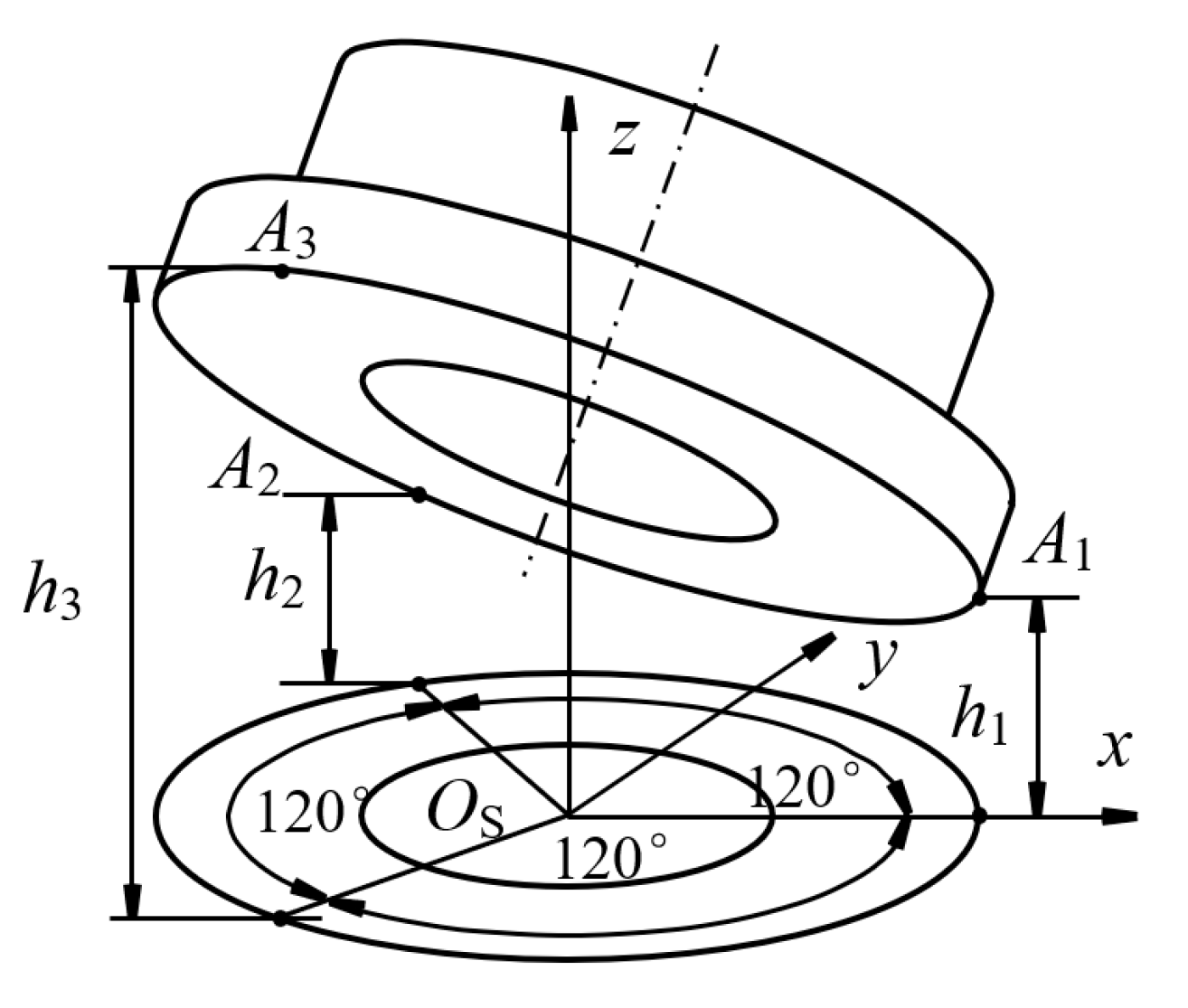
As shown in Figure 2, if the film thickness h1, h2, and h3 located at three reference points A1, A2, and A3 were known, the film thickness hg at the random point could be determined as [15,24]
h g = ( h 2 h 3 ) r sin θ 3 r 2 + 2 h 1 h 2 h 3 r cos θ 3 r 2 + h 1 + h 2 + h 3 3
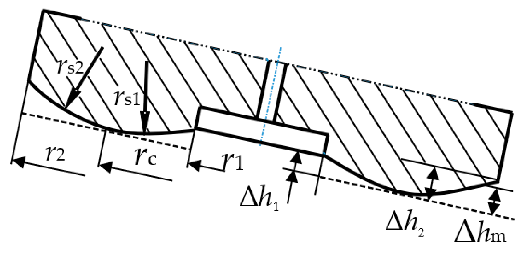
As shown in Figure 3, it is assumed that the slightly convex profile is symmetrical along the central axis, and the corrected film thickness caused by the wear Δhm is calculated as
Δ h m = r s 1 r s 1 2 r c r 2       r 1 r r c r s 2 r s 2 2 r r c 2       r c < r r 2
where r1 is the inner diameter of sealing, r2 is the outer diameter of sealing, rc is the radius of the wearing vertex, rs1 is the inside arc radius, and rs2 is the outside arc radius r c = λ r r 2 r 1 + r 1 , r s 1 = r c r 1 2 + Δ h i 2 2 Δ h i , r s 2 = r 2 r c 2 + Δ h o 2 2 Δ h o . λr is the relative position of the profile vertex in the sealing. Δhi is the height between the endpoint of the slipper profile at the inner circle and the top point of the profile on the bottom surface of the slipper. Δho is the height between the endpoint of the slipper profile at the outer circle and the top point of the profile on the bottom surface of the slipper.
The discrete expression of film thickness variation caused by the pressure elastic deformation could be described as [25,26]
Δ h p r i = 1 v e 2 π E j = 1 m k = 1 n + 1 p s L j , k ln ( r j r 2 ) ln r 1 r 2 1 r j Δ r Δ θ
where ps is pocket pressure, L j , k = r i 2 + r j 2 2 r i r j cos θ k   if   r j > r i r i 2 + r j 2 + 2 r i r j cos θ k   if   r j r i , νe is the Poisson’s ratio for the solid, and E is the elastic modulus for the solid.

2.5. Force Analysis

If the components of the centrifugal force and friction force of the piston-slipper assemblies along the shaft axis were ignored, the clamping force of the slipper along the axis direction FN could be expressed as
F N = F p + F s + F a cos β
where Fs is the return spring force, and Fa is the axial inertia force of piston-slipper assemblies F a = m s + m p a s and a s = R ω 2 tan β cos φ . rp is the diameter of the piston. ms is the mass of the slipper. mp is the mass of the piston. Fp is the force from the displacement chamber and F p = π r p 2 p p .
pp is displacement chamber pressure, and the latest expression can be found in [27], while the time-varying expression was adopted for the convenience of calculation, which is [28]
p p = K A p V 0 + A p s d s d θ j Δ θ 0 j 10 p o 10 j 170 p o K A p V 0 + A p s d s d θ j 170 Δ θ 170 j 180 p i 180 j 360
where V0 is the initial volume of the piston chamber; Ap is the area of the piston chamber; K is the volume modulus; j is the number; θ is the shaft rotational angle; Δθ is the rotational angle increment. Thermal equilibrium clearance s is piston displacement.
The bearing force on the bottom surface of the slipper FS could be calculated as
F S = p r π r 1 2 + r 1 r 2 0 2 π p r d r d θ
The overturning moment generated by the ball joint pair could be described as [9]
M B x = f bs F p R b sin φ s in β M B y = f bs F p R b cos φ s in β
where fbs is the friction factor of the ball joint pair and Rb is the radius of the ball head.
The overturning moment generated by the centrifugal force of the slipper can be expressed as
M L = m s l g ω s 2 R m
where lg is the distance between the barycenter of the slipper and the center of the ball head.
The anti-tilting moment generated by the normal stress and shear stress of the oil film is described as
M S x = r 1 r 2 0 2 π p r 2 sin θ d r d θ + l s 0 2 π r 1 r 2 τ r cos θ τ θ cos 90 ° θ r d r d θ M S y = r 1 r 2 0 2 π p r 2 cos θ d r d θ + l s 0 2 π r 1 r 2 τ r sin θ + τ θ sin 90 ° θ r d r d θ
where ls is the distance between the bottom surface of the slipper and the center of the ball head. τr is the radial shear stress at a random point expressed as τ r = p r h 2 + μ V r h , and τθ is the circumferential shear stress expressed as τ θ = p r θ h 2 + μ V θ h [24].
The force and moment balance equation can be described as
f h = f 1 h = F S h , h , t + F N t f 2 h = M S x h , h , t + M B x t + M L t f 2 h = M S y h , h , t + M B y t = 0
where h is the vector of oil thickness, h’ is the vector of the rate of oil thickness change, and t is the time.

2.6. Energy and Heat Transfer Equation

If the thermal convection and thermal radiation along the z direction are ignored, the energy equation of oil film in conservation form can be rewritten as [26]
c p ρ T t + 1 r r r c p ρ v r T λ T r + 1 r θ c p ρ v θ T λ T r θ + z c p ρ v z T λ T z = μ v r z 2 + v θ z 2
vr is the radial velocity of the fluid, vθ is the tangential velocity of the fluid, cp is the specific heat capacity of oil, and λ is the thermal conductivity of oil.
The heat transfer equation of slipper solid could be expressed as [28]
c ps ρ T s t λ s 1 r r r T s r + 1 r 2 2 T s θ 2 + 2 T s z 2 = 0
where cps is the specific heat capacity of the slipper, and λs is the thermal conductivity of the slipper.

2.7. Viscosity Temperature Equation

The oil viscosity is a function of temperature and pressure, the Roelands viscosity–temperature relationship be expressed as [29]
μ = μ 0 α p p + β t ( T T 0 )
where μ0 is the initial oil viscosity, αp is the viscosity pressure coefficient, βt is the viscosity-temperature coefficient, and T0 is the initial temperature.

2.8. Flow Balance Equation

The dynamic pressure equation in the pocket chamber can be calculated as
d p s d t = K V ( Q in Q out h 0 π r 1 2 )
where K is the oil bulk modulus, V is the volume of the pocket chamber and V = h0πr12, h0′ is the speed of slipper instantaneous motion in the z axis, and Qout is the oil outflow from the pocket chamber and can be obtained from the numerical solution. The oil inflow from displacement chamber Qin could be described as
Q in = 1 C e p p p s R f
where Ce is the correction coefficient of flow, and Rf is the liquid resistance of the damping hole at the piston head [30].

3. Numerical Solution

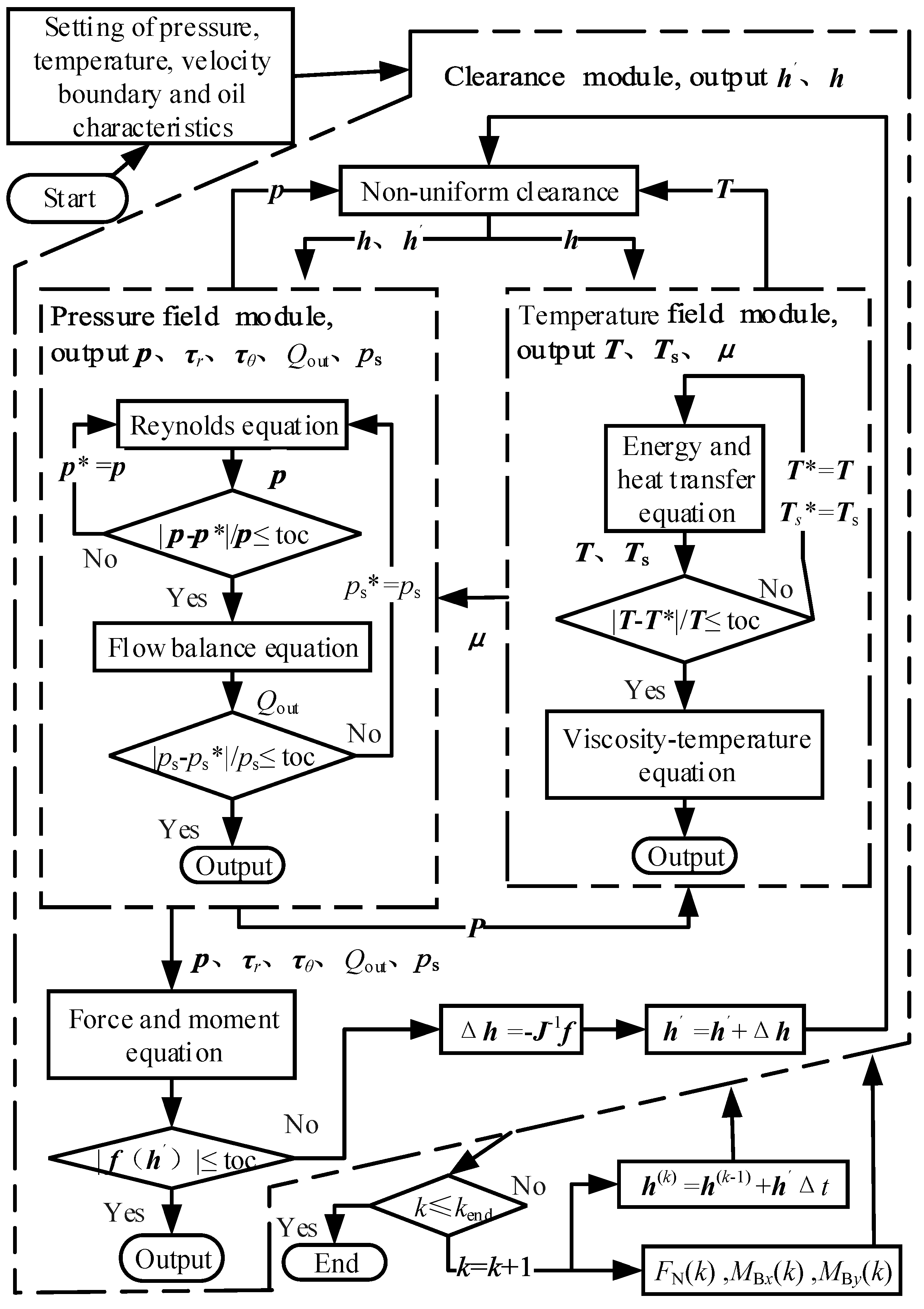
According to the finite volume method and Gauss theorem, the Reynolds equation and energy equation could be dispersed, and solved through the over-relaxation iteration method. The force and moment balance equation could be solved by the Newton iteration approach. The numerical solution diagram is shown in Figure 4. Based on the sequential coupling method, the pressure field p, the pocket chamber pressure ps, the leakage Qout, the temperature field of oil film T, the viscosity field μ, and the thickness field of oil film H could be renewed by the circulating revision, until the target function min (f(h′)) meets the convergence conditions [31]. The structural and operation parameters of the slipper are shown in Table 1, and are based on the wear process that was demonstrated in [17]. Then, the wear status could be defined as eight types, which are listed in Table 2, and the wear profile could be determined by three parameters, Δh1, Δh2 and λr, which are mentioned in equation 6. It should be mentioned at this point that the numbering of the types is not assigned according to the order they were demonstrated in, but rather in a systematic fashion increasing in Δh1, Δh2, and λr.
The multi-extremum equilibrium equations can be solved with consideration of the variable step size and confidence interval of the restricted solution, and then the pressure, temperature, viscosity, and thickness field of oil film could be obtained through the sequential cyclic iteration.

4. Results

The pressure field and thickness field under the sealing land of slipper B and slipper H are shown in Figure 5 when the operation is stable and φ = 45°. At this point, the slipper is subjected to a forward tilting moment. Under a relatively uniform gap, the pressure decreases exponentially along the radial direction. The pressure distribution is roughly consistent with the results in literature, [26] and [32], which neglected the wear profile but took into account the effect of thermo-hydrodynamics. However, when the gap is significantly uneven, the pressure distribution is significantly different from the results of previous studies.
Slipper B is tilted backward relative to the sliding direction and it forms a convergent wedgelike gap, which is shown in Figure 5c. The thickness field is symmetrical with the axis of y = 0, the minimum clearance point on the sealing land is located in the right semicircular, and the relative tilting angle is about 175°. Where the pressure of the oil film decreases exponentially along the radial direction [33], see Figure 5a, the integral value of the pressure in the left semicircle is higher than in the right semicircle, and the pressure in the lower semicircle is higher than in the upper semicircle.
Slipper H is slightly tilted forward relative to the sliding direction, and is presented in Figure 5d. A convergent wedgelike gap is formed on the outside of the left semicircular and the inside of the right semicircular, and, similarly, the divergence clearance is formed on the inside of the left semicircular and the outside of the right semicircular; the minimum clearance point on the sealing land is located in the third quadrants, and the relative tilting angle is 75°. Figure 5c shows that the pressure distribution decreases gently at the convergence clearance, and significantly at the divergence clearance.

4.1. Effect of Wear Profile on the Thickness under Slipper Sealing Land

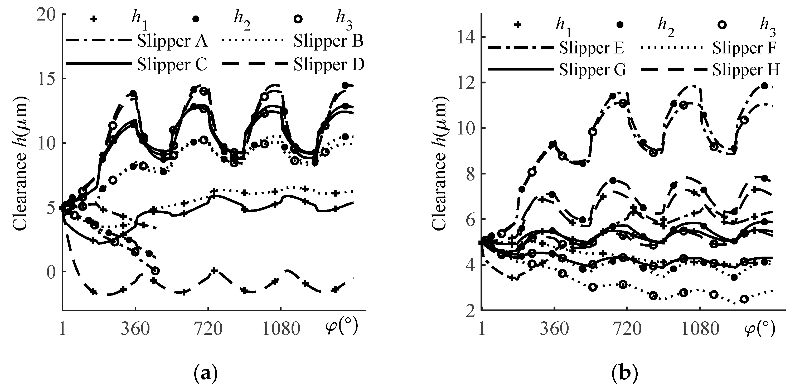
The relationship between the oil film thicknesses h1, h2, and h3 at three points on the sealing land at different wear statuses are shown in Figure 6a,b. This result is consistent with the literature [15]. Overall, 360° is an operation cycle, and the first half of each cycle represents the high pressure side, where the oil is discharged from the displacement chamber. When the second half is at the low pressure side, the oil is suctioned from the case. The values of thickness oscillate up to a stable state after the third operation cycle. The h1 value of slipper A is the largest among its three thickness values, which shows that the slipper is running in a forward inclination. As the rotation continues, the curves continuously descend, which shows the slipper squeezing the oil film until the lowest position of the running surface contacts the swashplate. The current version of numerical simulations does not incorporate the calculation of the wear of the parts, so the simulation is stopped. There is a trend visible suggesting that slipper A will be eccentrically worn. It can be seen that the h1 is the smallest at slipper B~slipper E, which shows that they run in a backward inclination. The amplitude and max thickness increases with the increase in Δho. This is in line with the theory of dynamic lubrication: the larger the wedge angle, the stronger the dynamic pressure effect. When the inner ring wear parameter is added, the h3 value of slipper F~slipper H is the smallest, and h2 takes second place. The amplitude becomes larger with the simultaneous increase in Δhi and Δho when the slipper is running in outwards and forwards inclinations.
The results show that the wear on the outside of the sealing land is conducive to the formation of a wedge-shaped clearance required for dynamic lubrication. A sufficient wear profile can provide the necessary dynamic bearing capacity for an underbalanced design slipper, avoiding continuous metal to metal contact between the slipper and the swashplate. However, even taking into account the elastic deformation, insufficient wear such as in slipper A may not establish complete fluid lubrication conditions.
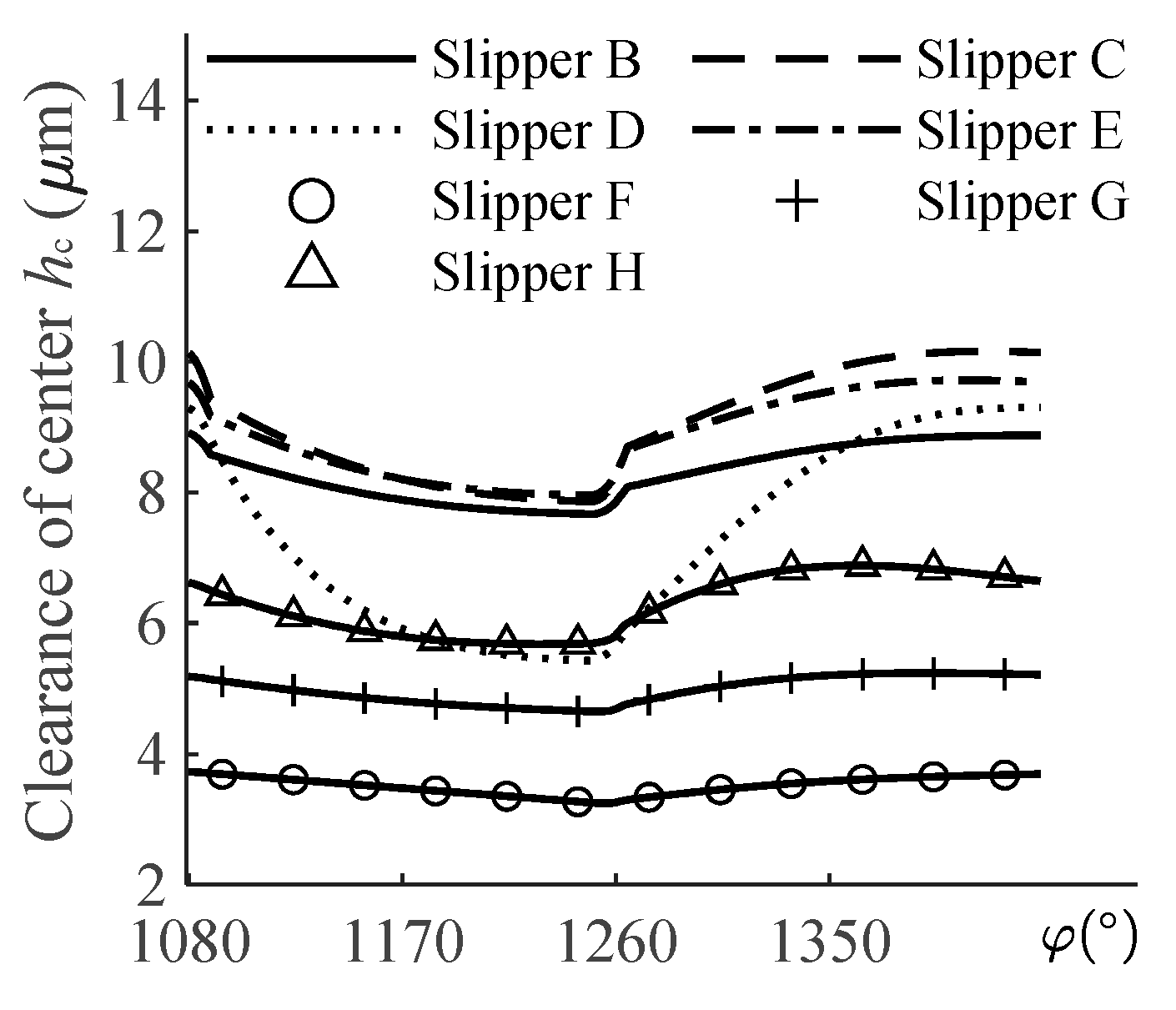
The curves of central thickness with rotation angles under different wear statuses are shown in Figure 7. The clamping force increased in the first half cycle; so, the oil film thickness is continuously descending. When the slipper enters the low pressure side, the central clearance gradually thickens. That is due to the reduction in elastic deformation and the change in inertia force. The thickness of the central oil film increases when Δho is slightly increasing, see the curves of slipper B, C, and E. The appropriate increase in Δho makes the dynamic lubrication effect enhanced; the slipper moves up and the central oil film becomes thicker. However, when the running surface is worn severely such as with slipper D, the dynamic bearing capacity is not enough to offset the loss of static pressure caused by tilting, and the whole oil film needs to be squeezed to balance the clamping force so that the central oil film will move down at the delivery phase. When considering the inner side wear, see the curves of slipper F, G and H, the dynamic bearing capacity is weakened. Therefore, the curve descends. It is equivalent to increasing the effective area of the pocket chamber with the increase in Δhi so that the bearing force of the slipper increases, and the oil film in the center of the slipper becomes thicker.
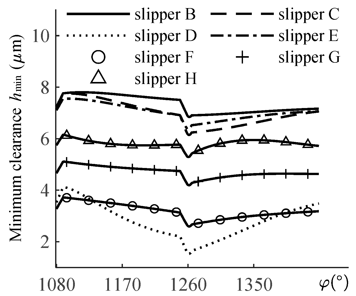
The curves of minimum oil film thickness with rotation angles under different wear statuses are shown in Figure 8. When the slipper enters the high pressure side, it does not seem very intuitive, and the thickness of the oil film increases rather than decreases. The reason is that the pressure increases sharply and the running surface of the slipper deforms elastically. Similar trends are observable when the slippers enter the low pressure side; the sudden decrease in pressure causes the elastic deformation of the running surface to recover and the thickness of the oil film to decrease sharply.

4.2. Effect of Wear Profile on the Sliding Attitude of the Slipper

The trajectories of the minimum clearance point for one cycle at different wear statuses are shown in Figure 9, and the markings show the position of the minimum clearance point on the sealing land. Slipper B~Slipper E are running in a backward inclination, and the maximum tilting angle increases in the range of 175~180° with the increase in Δho, while the minimum clearance point moves inward along the radial direction. Slipper F~Slipper H are running in an outward and forward inclination, and the maximum tilting angle increases in the range of 35° to 75°, with the simultaneous increase in Δhi and Δho.
The curves of the maximum tilting angle in one cycle are shown in Figure 10, and the result shows the slipper tilts more obviously at the suction phase than at the delivery phase. The curves of the maximum tilting angle of slipper B~slipper E shifts upward, and the swing amplitude increases with the increase in Δho. The curve of slipper E shifts down significantly but swings more gently compared to slipper C which has the same value of Δho but a larger value of λr. It can be seen that the increase in λr contributes to the control of the maximum tilting angle. The anti-tilting capacity of the running surface is increased after taking Δhi into account. The maximum tilting curve of slipper F~slipper H decreases significantly, and increases slightly with the simultaneous increase in Δhi and Δho.

4.3. Effect of Wear Profile on Leakage of Slipper

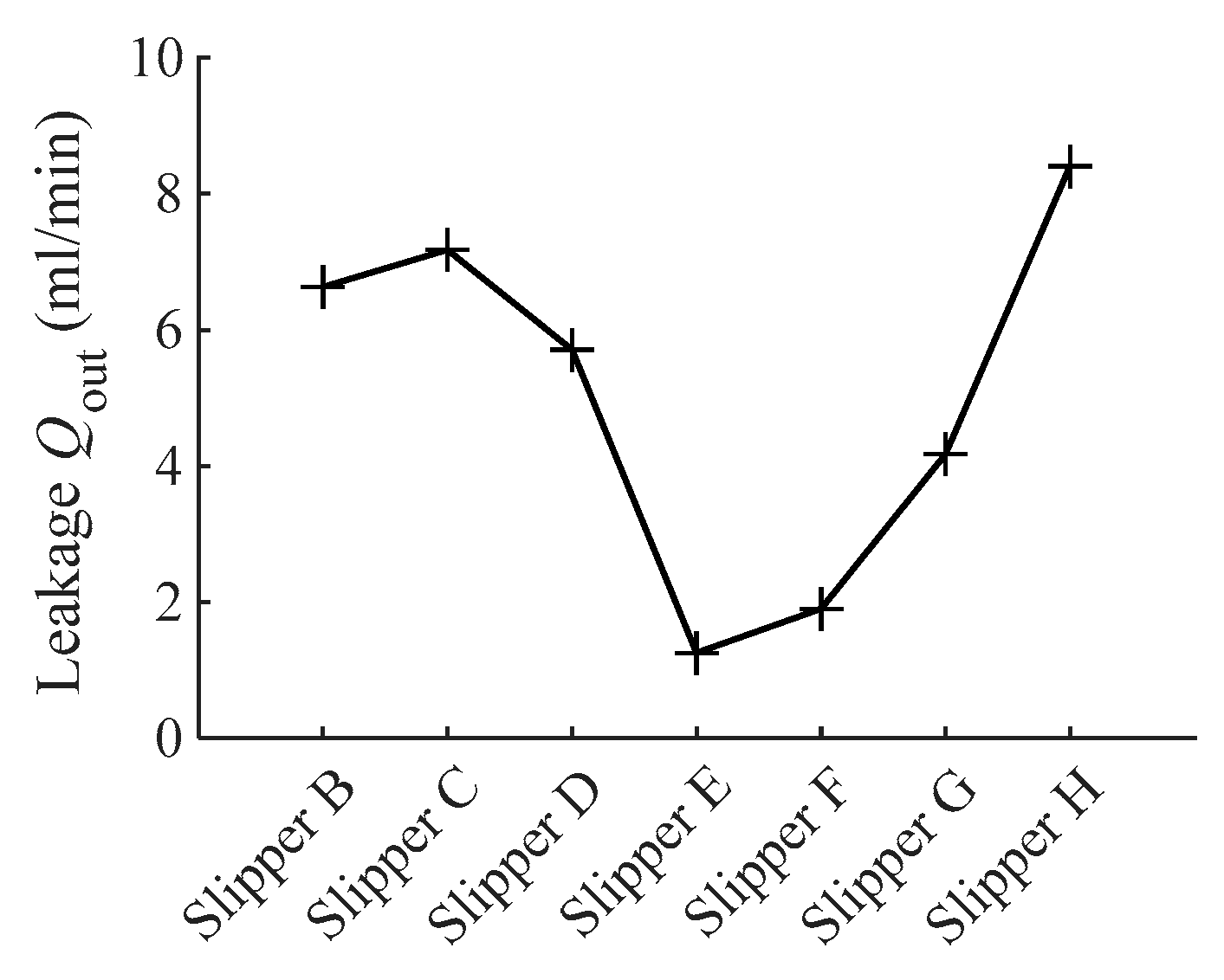
The average leakage of the slipper at the delivery phase for different wear statuses is shown in Figure 11. Leakage is related to the sealing clearance and sliding attitude. According to the variations in the central clearance presented in Figure 7, the leakages of slipper B~slipper E increase first and then decrease accordingly. It is worth noting that the slipper E wear contour vertex is shifted by 50% of the sealing land width compared with slipper C, and the leakage is decreased by 75.30%. The leakages of slipper F~slipper H, in line with the central clearance, gradually increase with the simultaneous increase in Δhi and Δho.

5. Conclusions

The wear profile of the sealing land is an important boundary condition for the slipper. The effects on film thickness, running attitude, and leakage are remarkable.
1. When the wear height of outer side of the sealing land Δho increases moderately, the dynamic bearing force increases and the oil film becomes thicker. At the same time, the anti-forward tilt ability is enhanced, and the backward tilt angle and leakage of the slipper are increased also. When the outer side of the sealing land is seriously worn, which is decided by the working conditions, see slipper D. The dynamic lubrication effect is significantly enhanced and the back inclination is increased. However, the uneven clearance and the large inclination angle increase the loss of static pressure under the sealing land; this will weaken the squeezing effect, reduce the stiffness of the film, and increase the swing amplitude of the slipper.
2. The wear contour vertex moves out and will reduce the length of the wedge gap and will suppress the dynamic lubrication effect. With the same wear height as the outer side, the slipper E wear contour vertex is moved out by 50% of the sealing land width compared with slipper C; the central film thickness is decreased by 1.85%, the minimum film thickness is increased by 0.81%, the inclination is decreased by 27.77%, and the leakage is decreased by 75.30%.
3. Wear on the inner side of the sealing land also reduces the length of the wedge gap; additionally, it increases the unevenness of the bottom surface. As a result, the static pressure distribution on the bottom surface is mainly concentrated on the inner side, resulting in a decrease in the anti-inward and anti-outward tilting abilities of the slipper.
Under the premise of suitable center oil film thickness and minimum oil film thickness, controlling appropriate outer wear and avoiding inner wear can improve the lubrication performance of the slipper pair.

Author Contributions

Validation, Y.H.; Resources, S.Q.; Writing—original draft, H.M. All authors have read and agreed to the published version of the manuscript.

Funding

This work was financial supported by the Scientific Research Foundation of Hunan Educational Committee (No. 22C0797) and Technology Research and Development Program of XiangTan (No. CG-YB20211026).

Data Availability Statement

Not applicable.

Conflicts of Interest

The authors declare no conflict of interest.

References

  1. Ransegnola, T.; Shang, L.; Vacca, A. A study of piston and slipper spin in swashplate type axial piston machines. Tribol. Int. 2022, 167, 107420. [Google Scholar] [CrossRef]
  2. Xu, B.; Zhang, J.H. Effect of case drain pressure on slipper/swashplate pair within axial piston pump. J. Zhejiang Univ.—Sci. A Appl. Phys. Eng. 2015, 16, 1001–1014. [Google Scholar] [CrossRef]
  3. Wu, H.C.; He, Y.Y.; Jian, X.S. Numerical Analysis of Influence of Slipper Bottom Structure on Oil Film Performance of Slipper Pair of Axial Piston Pump. Lubr. Eng. 2014, 39, 1–5. [Google Scholar]
  4. Li, Z.; Xu, S.; Gong, G.; Bi, Y.; Xu, L.; Zhang, L.; Ren, Z. Study on Friction Characteristics of Slipper Pair of Large Displacement High-Pressure Piston Pump. Lubricants 2022, 10, 363. [Google Scholar] [CrossRef]
  5. Mo, H.; Guo, Y.; Quan, S. Effect of Texture on Total Energy Consumption of High, Frequency Hydraulic Impact Piston Pair. Coatings 2022, 12, 340. [Google Scholar] [CrossRef]
  6. Chao, Q.; Zhang, J.; Xu, B.; Wang, Q.; Huang, H. Test rigs and experimental studies of the slipper bearing in axial piston pumps: A review. Measurement 2018, 132, 135–149. [Google Scholar] [CrossRef]
  7. Harris, R.; Edge, K.A.; Tilley, D.G. Predicting the behavior of slipper pads in swashplate-type axial piston pumps. J. Dyn. Syst. Meas. Control. ASME 1996, 118, 41–47. [Google Scholar] [CrossRef]
  8. Borghi, M.; Specchia, E.; Zardin, B. Numerical analysis of the dynamic behavior of axial piston pumps and motors slipper bearings. Int. J. Passeng. Cars–Mech. Syst. SAE 2009, 2, 1285–1302. [Google Scholar] [CrossRef]
  9. Hooke, C.J.; Kakoullis, Y.P.S. The Effects of centrifugal load and ball friction on the lubrication of slippers in axial piston pumps. In Proceedings of the 6th International Fluid Power Symposium, Cambridge, UK, 8–10 April 1981. [Google Scholar]
  10. Hooke, C.J.; Kakoullis, Y.P. The Effects of non-flatness on the performance of slippers in Axial Piston Pumps. Proc. Inst. Mech. Eng. Part C J. Mech. Eng. Sci. 1983, 197, 239–247. [Google Scholar] [CrossRef]
  11. Manring, N.D.; Johnson, R.E.; Cherukuri, H.P. The impact of linear deformations on stationary hydrostatic thrust bearings. J. Tribol. ASME 2002, 124, 874–877. [Google Scholar] [CrossRef]
  12. Wieczorek, U.; Ivantysynova, M. CASPAR—A Computer Aided Design Tool for Axial Piston Machines. In Proceedings of the Bath Workshop on Power Transmission and Motion Control PTMC 2000, Bath, UK, 1 November 2000; pp. 113–126. [Google Scholar]
  13. Schenk, A. Predicting Lubrication Performance between the Slipper and Swashplate in Axial Piston Hydraulic Machines; Purdue University: West Lafayette, IN, USA, 2014. [Google Scholar]
  14. Schenk, A.; Ivantysynova, M. A Transient Thermoelastohydrodynamic Lubrication Model for the Slipper/Swashplate in Axial Piston Machines. J. Tribol. 2015, 137, 031701. [Google Scholar] [CrossRef]
  15. Liu, H.; Yuan, S.H.; Jing, C.B.; Zhao, Y. Effects of Wear Profile and Elastic Deformation on the Slipper’s Dynamic Characteristics. J. Mech. Eng. 2013, 49, 75–83. [Google Scholar] [CrossRef]
  16. Koc, E.; Hooke, C.J.; Li, K.Y. Slipper Balance in Axial Piston Pumps and Motors. J. Tribol. 1992, 114, 766–772. [Google Scholar] [CrossRef]
  17. Ivantysyn, R.; Shorbagy, A.; Weber, J. Investigation of the wear behavior of the slipper in an axial piston pump using simulation and measurement. In Proceedings of the 12th International Fluid Power Conference 2020, Dresden, Germany, 9–11 March 2020; pp. 315–326. [Google Scholar]
  18. Darbani, A.A.; Shang, L.; Beale, J.R.; Ivantysynova, M. Slipper Surface Geometry Optimization of the Slipper/Swashplate Interface of Swashplate-Type Axial Piston Machines. Int. J. Fluid Power 2019, 20, 245–270. [Google Scholar] [CrossRef]
  19. Chao, Q.; Zhang, J.; Xu, B.; Wang, Q.; Lyu, F.; Li, K. Integrated slipper retainer mechanism to eliminate slipper wear in high-speed axial piston pumps. Front. Mech. Eng. 2022, 17, 1. [Google Scholar] [CrossRef]
  20. Li, H.L.; Liu, F.G.; Zhang, B.M. Improvement of Slipper Wear Failure Mode. Hydraul. Pneum. Seals 2015, 35, 75–78. [Google Scholar]
  21. Zhang, J.; Chao, Q.; Wang, Q.; Xu, B.; Chen, Y.; Li, Y. Experimental investigations of the slipper spin in an axial piston pump. Measurement 2017, 102, 112–120. [Google Scholar] [CrossRef]
  22. Koc, E.; Hooke, C.J. Considerations in the design of partially hydrostatic slipper bearings. Tribol. Int. 1997, 30, 815–823. [Google Scholar] [CrossRef]
  23. Tang, H.S.; Yin, Y.B.; Liu, J. Thermal-structural coupling characteristics of axial piston pump slipper pair. J. Aerosp. Power 2016, 31, 1913–1920. [Google Scholar]
  24. Chao, Q. Derivation of the Reynolds equation in cylindrical coordinates applicable to the slipper/swash plate interface in axial piston pumps. Proc. Inst. Mech. Eng. Part J J. Eng. Tribol. 2020, 235, 798–807. [Google Scholar] [CrossRef]
  25. Christensen, H. Elastohydrodynamic Theory of Spherical Bodies in Normal Approach. Trans. Asme J. Lub. 1970, 92, 145–154. [Google Scholar] [CrossRef]
  26. Tang, H.S.; Ren, Y.; Xiang, J.W. A novel model for predicting thermoelastohydrodynamic lubrication characteristics of slipper pair in axial piston pump. Int. J. Mech. Sci. 2017, 124–125, 109–121. [Google Scholar] [CrossRef]
  27. Chao, Q.; Xu, Z.; Tao, J.; Liu, C. Capped piston: A promising design to reduce compressibility effects, pressure ripple and cavitation for high-speed and high-pressure axial piston pumps. Alex. Eng. J. 2023, 62, 509–521. [Google Scholar] [CrossRef]
  28. Tang, H.S.; Yin, Y.B.; Zhang, Y.; Li, J. Parametric analysis of thermal effect on hydrostatic slipper bearing capacity of axial piston pump. J. Cent. South Univ. 2016, 23, 333–343. [Google Scholar] [CrossRef]
  29. Roelands, C.J.A.; Vulger, J.C.; Waterman, H.I. The Viscosity-Temperature-Pressure Relationship of Lubricating Oils and Its Correlation with Chemical Constitution. Trans. ASME J. Trib. Tech. 1963, 85, 601–605. [Google Scholar] [CrossRef]
  30. Xu, Y.M. Oil Film Theory and the Design of Friction Pairs for Hydraulic Pumps and Motors; China Machine Press: Beijing, China, 1987; pp. 25–27. [Google Scholar]
  31. Liu, S.; Hu, J. Tribo-dynamic model of slipper bearing. Appl. Math. Model. 2015, 39, 548–558. [Google Scholar]
  32. Fu, J.F.; Li, H.C.; Zeng, X.Q.; Liu, X. Numerical simulation of hybrid lubrication characteristics of slipper pair of aviation fuel piston pump. J. Beijing Univ. Aeronaut. Astronaut. 2018, 44, 939–950. [Google Scholar]
  33. Hu, J.B.; Zhou, H.C.; Wei, C.; Liu, H. Theoretical and Experimental Research on the Formation of Lubrication Film for Slipper Bearings of Axial Piston Pumps. Trans. Beijing Inst. Technol. 2015, 35, 231–235. [Google Scholar]
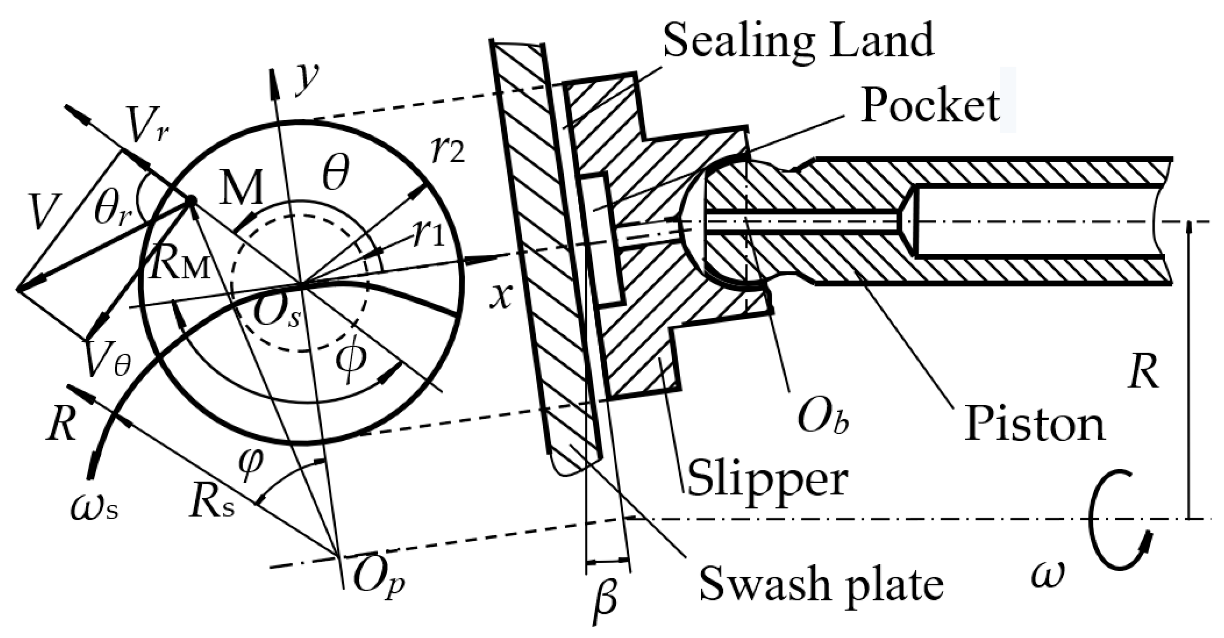
Figure 1. Structure and motion of slipper pair.
Lubricants 11 00190 g001
Figure 2. Description of ideal sealing surface based on 3-point film thickness.
Lubricants 11 00190 g002
Figure 3. Description of the wear sealing surface.
Lubricants 11 00190 g003
Figure 4. Diagram of the numerical solution.
Lubricants 11 00190 g004
Figure 5. Pressure and thickness field under the sealing land: (a) The pressure field of slipper B. (b) The pressure field of slipper H. (c) The thickness field of slipper B. (d) The thickness field of slipper H.
Lubricants 11 00190 g005
Figure 6. Curves of 3-point clearance: (a) Slipper A–D. (b) Slipper E–H.
Lubricants 11 00190 g006
Figure 7. Curves of central clearance.
Lubricants 11 00190 g007
Figure 8. Curves of minimum clearance.
Lubricants 11 00190 g008
Figure 9. Paths of the lowest point under the sealing surface.
Lubricants 11 00190 g009
Figure 10. Curves of tilting angle.
Lubricants 11 00190 g010
Figure 11. The curve of average leakage at the delivery phase.
Lubricants 11 00190 g011
Table 1. The basic structure and operating parameters for the slipper.
NameUnitValue
Inner radius of sealing land r1mm6.4
Outer radius of sealing land r2mm12.8
Radius of ball head Rmm44
Outer radius of piston rpmm9.5
Pressure of piston ppMpa10
Angular velocity of ball head ωrpm1500
Inclination of swash plate β°14
Initial viscosity of hydraulic oil μ0mm2/s30.69
Table 2. Parameters for wear profile.
TypesProfile ParametersTypesProfile Parameters
Δhi
μm
Δho
μm
λrΔhi
μm
Δho
μm
λr
A00.010.1E020.5
B010.1F110.5
C020.1G220.5
D080.1H550.5
Disclaimer/Publisher’s Note: The statements, opinions and data contained in all publications are solely those of the individual author(s) and contributor(s) and not of MDPI and/or the editor(s). MDPI and/or the editor(s) disclaim responsibility for any injury to people or property resulting from any ideas, methods, instructions or products referred to in the content.