Article

Tilting-Pad Bearings—The Contact Flexibility of the Pivot

by
Laurence F. Wagner
Rotor Bearing Solutions International LLC., 5211 Mountainview Rd., Winston Salem, NC 27104, USA
Lubricants 2023, 11(5), 189; https://doi.org/10.3390/lubricants11050189
Submission received: 24 March 2023 / Revised: 17 April 2023 / Accepted: 24 April 2023 / Published: 25 April 2023

Abstract

:
The modeling of tilting-pad journal and thrust bearings presents a level of complexity beyond that of bearings with a fixed-arc geometry, particularly with regard to their dynamic influences. With tilting-pad bearings, the theory surrounding their fluid film must be complemented with the representative modeling of the pad dynamics. What has been recognized in recent decades is the significance of the pad support, in particular the flexibility of the pivot region of the pad. The typical model for including the stiffness of the pivot is based on the Hertzian contact theory. Some researchers have noted that the Hertzian theory does not permit sufficient flexibility in the pivot region. It has been suggested that the contact mechanics at the pivot would be better represented as a pairing of rough surfaces. The modeling used here is based on a statistical asperity micro-contact theory for rough surface line contact that has been extended to include contact stiffness. This model has been applied to the determination of the effective dynamic properties of tilting-pad bearings. The results show that pivot stiffness can be as low as one third of the stiffness determined by the Hertzian theory. A comparison to published experimental results confirms the significance of the rough surface modeling, particularly for the line contacts associated with rocker-back tilting pads.

1. Introduction

Most readers are likely familiar with the geometry and operation of tilting-pad journal bearings (TPJB). These bearings are mechanically complex, having multiple pads with various loading arrangements, e.g., load-on-pad (LOP) or load-between-pads (LBP). They are available in many commercial variations, e.g., spherical pivots (point contact), rocker pivots (line contact), and flexure pivots. It has become well known that the flexibility of these pivots can significantly affect the dynamic properties of tilting-pad bearings. However, based on experimental measurements, the current theory for pivot stiffness determination results in pivots that are too stiff. One reason for this deficiency is likely to be the neglect of surface roughness at the contact.
When two bodies with rough surfaces are pressed together, the true contact area formed between the two bodies is much smaller than the apparent or nominal contact area. This is attributed to natural and machined surfaces that typically exhibit roughness features, known as asperities, which occur across a broad range of length scales. These asperities create the principal paths for the flow of heat, electricity, and force. The parameters describing the asperity distribution are statistically based on asperity size (width and height) and spatial density.
The objective of this paper is to use one of the prominent rough surface theories combined with an extension to compute the stiffness for an application to the pivot stiffness problem confronting researchers in tilting-pad bearing technology. A schematic of the typical contact region for a TPJB pad is shown in Figure 1.
Although most of the ideas presented here apply to all rough surface contact situations, this paper is primarily concerned with the line or cylindrical contact.

2. Literature Survey

2.1. Research on Pivot Flexibility

The recognition of the relative independence of each pad of a TPJB has led to a method that would allow computations for the complete bearing performance, based upon the assembly of results for each pad. In 1964, Lund [1] published the first paper focused on TPJB dynamic coefficients using such an assembly method. This method was known as “Lund’s pad assembly method”, and now is commonly known as the KC method (K for stiffness and C for damping). In 1977, Shapiro and Colsher [2] provided further documentation, considering an eigenvalue reduction for the real part, and included example analyses. In 1983, Allaire et al. [3] presented a similar pad assembly method and extended the Shapiro and Colsher complex eigenvalue reductions to include both the real and imaginary parts, an important improvement related to the rotor stability computations. Both of these methods involved shaft translation and individual pad rotation degrees of freedom (DOF), as well as coupling between these DOFs. The KC model is often referred to as the “full bearing coefficient model”, and is mentioned here as the “pad assembly method”.
In the late 1970s and early 1980s, researchers began to recognize the significance of the pivots supporting each pad of a TPJB, and how the pivot flexibility affected the bearing dynamic characteristics. Rouch [4] implemented the pivot flexibility parameter into the pad assembly method by including a radial DOF for the pad. A reduction in the full stiffness and damping matrices for nonsynchronous frequencies indicated the significance of the pivot flexibility, in particular for the rotor stability determination. This work by Rouch provides an excellent description of the KC or pad-assembly method.
Following this work by Rouch, researchers involved with the study of TPJB pivot effects began using formulas for the pressure and deflection between two elastic surfaces based on the results of H. Hertz from an 1895 German paper. These formulas have generally been used to model the pad contact stiffness; can be found in Roark [5], and are categorized in a paper by Kirk and Reedy [6], specifically for engineers involved with TPJB design and specification.
Over the next two decades, most of the follow-on works involving pivot stiffness were centered on experimentation, and there is insufficient space to discuss them all. The experiments were not specifically related to pivot stiffness, but to bearing coefficients in general. One of the earliest experiments with published results was documented in the 1999 paper by Pettinato and De Choudhury [7]. They measured the TPJB dynamic properties and found that the pivot flexibility reduced the effective bearing stiffness and damping, and that a key seat (cylindrical) pivot exhibited a higher stiffness and damping than a spherical pivot did.
Dmochowski [8] performed experiments on a five-pad bearing and concluded that pivot flexibility and pad inertia could have significant effects on a TPJB’s dynamic properties. Pivot flexibility was noted to provide either an increase or decrease in the bearing stiffness coefficients, depending on the operating conditions and bearing design.
Harris and Childs [9] directly measured the pivot stiffness for a single pad of a four-pad ball-in-socket TPJB. They found that, unlike the Hertzian result, the load versus the deflection plot was linear over the range of the loads considered.
In a 2011 paper, Dimond, Younan, and Allaire presented an excellent review of the tilting-pad journal bearing literature [10]. Theoretical and modeling issues were the primary concerns, with a note that some modeling options rely on the results of experimentation. This paper provided a section on the review of TPJB dynamic models, with an overview on the approximate KCM (K stiffness, C damping, and M mass) experimentally identified model. This model determines the constant (frequency-independent) coefficient values and is based on curve fitting experimental results, not first principles, thus making it subject to the potential vagaries of the experimental process. The KCM model is useful in many applications, but some important parameters, typically those related to single-pad DOF’s, cannot be explicitly included in its analysis, and from the perspective of the current paper, pivot flexibility is one of these parameters.
Wilkes and Childs presented a paper in 2012 [11] that encompassed many aspects of TPJB’s, including their pivot flexibility. The work concluded that the inclusion of pivot flexibility is a requirement for both static and dynamic property calculations.
San Andres and Tao [12] investigated the aspects of pivot flexibility via a parametric analysis. It was shown that there are regions of pivot stiffness where either the pivot dominates the effective dynamic properties, or the fluid film dominates.
In 2019, through comparison to an experiment, Dang et. al. [13] showed that the Hertz contact theory overestimates the pivot stiffness, particularly for a rocker-backed bearing that experienced a 30% lower stiffness than that determined by the Hertz formula. The measurements also showed that both the TPJB effective stiffness and damping varied significantly over the frequency range.
Shi, Jin, and Yuan reported numerical results on the effects of the pivot design on its nonlinear rotor dynamics in 2019 [14]. They used a Hertzian pivot model to show that an elastic pivot results in larger journal orbits, and that the pivot deformations nonlinearly increase with an increasing unbalance. They showed that a spherical pivot is more compliant than a cylindrical pivot.
In 2022, Wagner and Allaire [15] studied the frequency dependency related to TPJB pivots. They showed the significant effect of pivot stiffness on the variation in the TPJB dynamic properties with whirl frequency. With reference to the most important range of frequencies, up to and below synchronous, increasing the pivot flexibility monotonically reduced both the effective stiffness and damping curves, with a tendency to “flatten” the curves over the frequency range. It was noted that this pivot behavior is likely a reason for the measured stiffness and damping, in particular, to be claimed as constants.
The most significant conclusion drawn from the literature concerning these pivot effects is that, although it has been shown that there is universal concern about the significance of pivot flexibility, there has been no related theoretical examination beyond the theory of Hertz.

2.2. Rough Surface Research

The early work of Hertz was based on elastic material behavior, allowing for a determination of the relative deformation and contact area between two ideally smooth bodies as the result of an applied load. However, it has long been known that all the surfaces must be considered “rough” on a microscopic scale.
When two rough-surfaced bodies are pressed together, only their asperities or surface peaks will be in contact, and these peaks will carry very high loads. The high loads will also cause many of the asperities to yield, thus invalidating the models based purely on elastic contact. Additionally, the actual area of contact is much smaller than the Hertzian-computed or nominal area.
Although not related to line contact, the work of Greenwood and Tripp [16], related to rough spherical contact, claimed that, at low loads, the actual contact pressure in the presence of roughness is one third that of the theoretical smooth Hertzian contact pressure. Additionally, Shi and Polycarpou [17] stated that the contact stiffness at light loads will be approximately one third of the Hertzian result, irrespective of the roughness level, and that this approximation is often adopted by researchers. These statements give support to the need to abandon the Hertzian theory for an accurate determination of the surface contact stiffness.
One of the first and best-known models of asperity contact was documented by Greenwood and Williamson [18]. They extended the elastic Hertzian solution to the contact of a population of asperities with a Gaussian height distribution. The rough surface was assumed to contact a rigid, flat plane. The asperities were taken to be independent and the bulk material beneath the asperities did not deform.
In 1986, Kagami et al. [19] published an approximate method for dealing with rough surfaces with a cylindrical curvature, including the effects of the bulk material deformation and asperity plasticity. This paper presented a procedure and results for rough-surface compliance and concluded that the Hertzian results did not conform with either the theory or experiment.
One of the first practical rough surface models was developed by Jackson and Green (JG) [20] and was guided by the results of a finite element analysis. This method, based on the separation of two flat surfaces, provided a more realistic model than that of Greenwood and Williamson by permitting the asperity deformation to be elastic, elastic–plastic, or fully plastic.
The rough surface statistical line contact model used in the current work was developed in 2012 by Beheshti and Khonsari (BK) [21], who used the JG developments along with the theories of several other researchers to determine the contact properties for curved rough surfaces with an initial contact along a line. This extension of the JG work, in addition to the asperity deformation that included plasticity, considered the elastic deformation of the bulk surfaces. Predictive expressions were developed for the pressure distribution, contact width, and real area of contact, and the basic theory of this has been followed as the basis for the current work. However, BK presented no results for the gross deformation along the load line; these results are required for a stiffness determination.

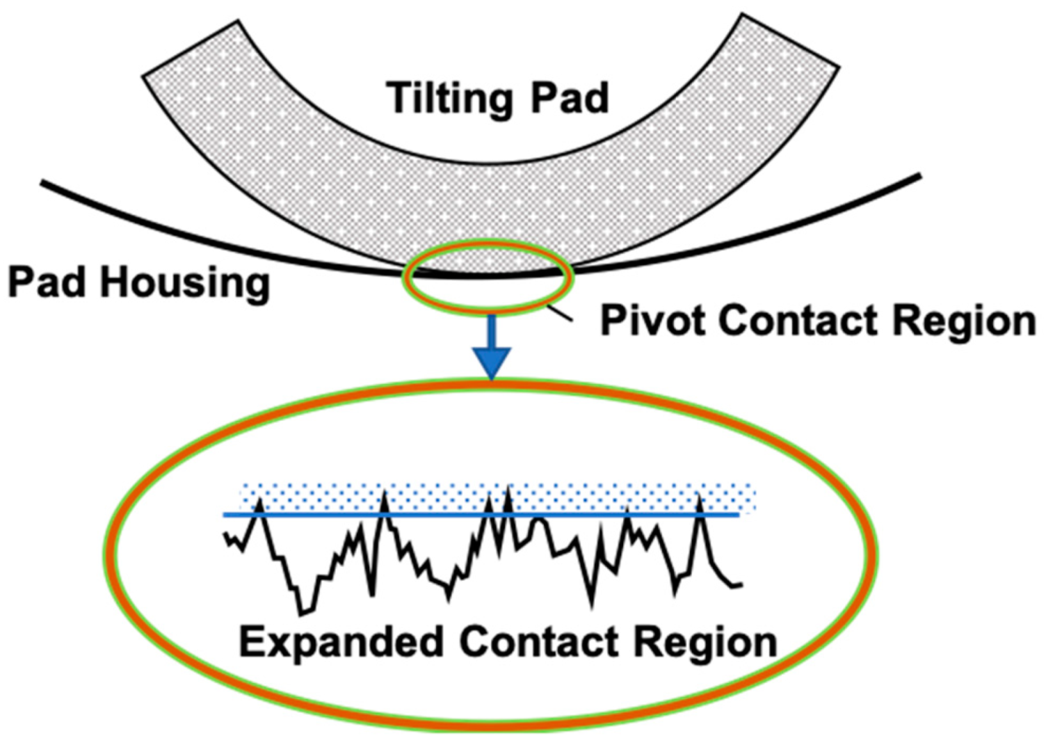
3. Modeling the Pivot Line Contact

Much of the presentation in this section follows the works of [20,21], with some variations involving the technique of the solution and extensions for providing compliance and stiffness.

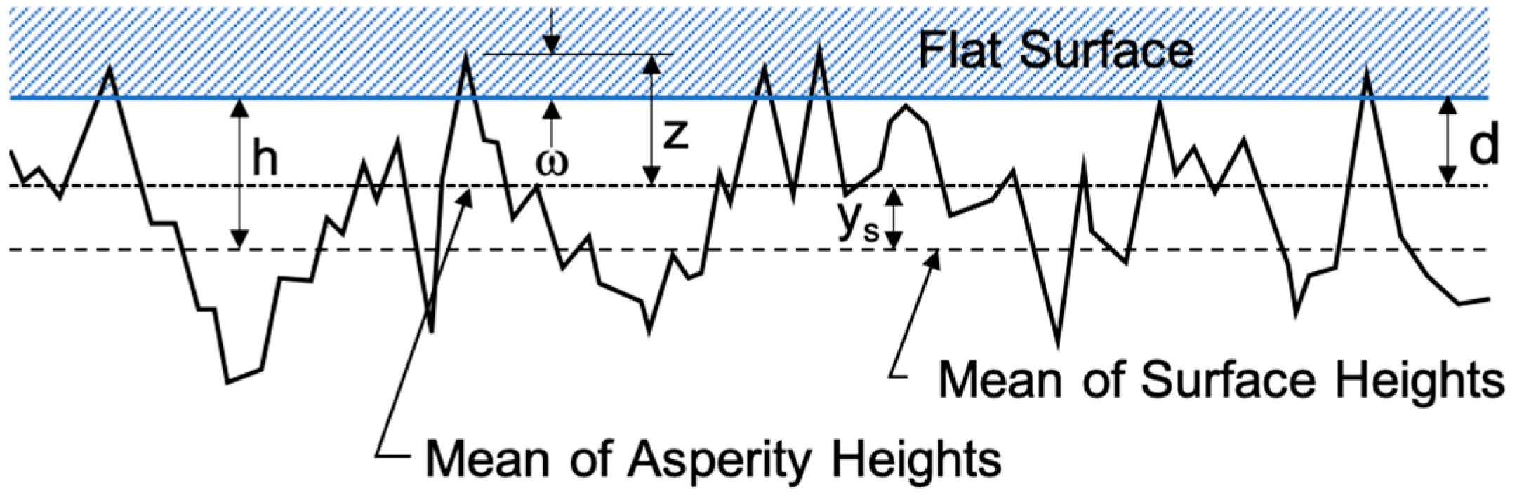
3.1. Contact of Two Flat Rough Surfaces

The modeling used here follows a statistical approach that first requires the establishment of a relationship for the contact of a single asperity, and then extends this to a population of asperities with heights following a Gaussian distribution. The principal assumptions are that the asperities all have the same spherical radius at the peaks, that the peak heights vary with a Gaussian distribution, and that they deform without interacting with the neighboring asperities. Additionally, it was shown in [16] that the contact of two rough surfaces can be modeled by an equivalent single rough surface contacting an ideally smooth plane, or vice versa. The effects of sliding or adhesion have been ignored.
The interest in the present paper involves the contact of curved surfaces, but the method will first compute and tabulate the pressures caused by bringing flat surfaces together under various loads using the JG theory [20]. The pressures that are then developed due to the varied surface separations at different points caused by the curvature will be sampled from the tabulation.
When dealing with contacting rough surfaces, two reference planes are defined. The first is the mean of the asperity heights and the second is the mean of the surface heights. In Figure 2, z and d denote, respectively, the asperity height and the separation of the asperity mean and ideally flat surfaces. The surface separation h is measured from the plane defined by the mean of the original surface heights. The interference ω is defined as ω = z − d.
There are basically six parameters required to define a single rough surface for the JG computations; three for the material and three for the surface geometry. For the material, we need,
(a)
the elastic modulus E,
(b)
Poisson’s ratio ν, and
(c)
the yield stress Sy,
and for the geometry,
(d)
the standard deviation σ of the asperity peak height,
(e)
the radius value β assigned to the tip of each asperity, and
(f)
the density of the peaks η (the number of peaks per unit area).
Using a surface roughness parameter of ξ = ηβσ, McCool [22] established the relationship between the standard deviations of the two reference surfaces, i.e.,
σ s σ = 1 3.717 × 10 4 ξ 2   and   y s σ = 0.04594 ξ
where σs is the standard deviation of the summit (asperity) heights.
The asperity height function is made dimensionless via σ and z ¯ = z/σ. The dimensionless Gaussian probability function φ z ¯ , which is required to statistically define the asperity height functions, is given by,
φ z ¯ = 1 2 π σ σ s exp 1 2 σ σ s 2 z ¯ 2
The effective elastic modulus E for the two surface materials, also used by Hertz, is defined by,
1 E = 1 ν 1 2 E 1 + 1 ν 2 2 E 2
where Ei and νi are the elastic moduli and Poisson’s ratio for the two materials.
The JG model considers the variation in the material hardness during the asperity deformation with an inclusion of the material yield strength, and defines a critical interference ω ¯ c that marks the transition from an elastic to elastic–plastic deformation, i.e.,
ω ¯ c = S ¯ y π C 2 2 β σ
with S ¯ y = S y / E and C = 1.295exp(0.736ν). The effective yield strength and Poisson’s ratio are associated with the softer material.
The following relationship for the pressure between rough flat surfaces has been provided with the JG model, namely,
p h = η β σ E Φ h
where,
Φ h = 4 3 σ β d ¯ d ¯ + 1.9 ω ¯ c ω ¯ 3 / 2 φ z ¯ d z ¯ + C π S ¯ y 2 d ¯ + 1.9 ω ¯ c Γ 1 + Γ 2 Γ 3 φ z ¯ d z ¯
with,
Γ 1 ( ω ¯ ) = e x p 1 4 ω ¯ ω ¯ c 5 / 12 ω ¯ 3 / 2 ω ¯ Γ 2 ( ω ¯ ) = 1 e x p 0.82 ω ¯ σ β ω ¯ 1.9 ω ¯ c D / 2 0.7 Γ 3 ( ω ¯ ) = 11.36 C ω ¯ 1 e x p 1 25 ω ¯ ω ¯ c 5 / 9
and D = 0.14 e x p ( 23 S ¯ y ) , ω ¯ = z ¯ d ¯ , and d ¯ = d/σ = (h − ys)/σ

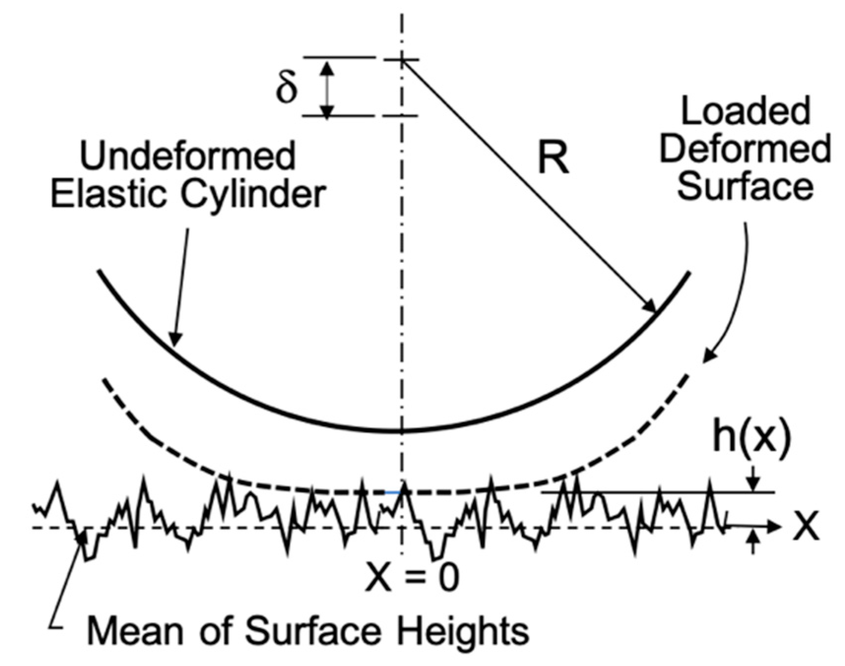
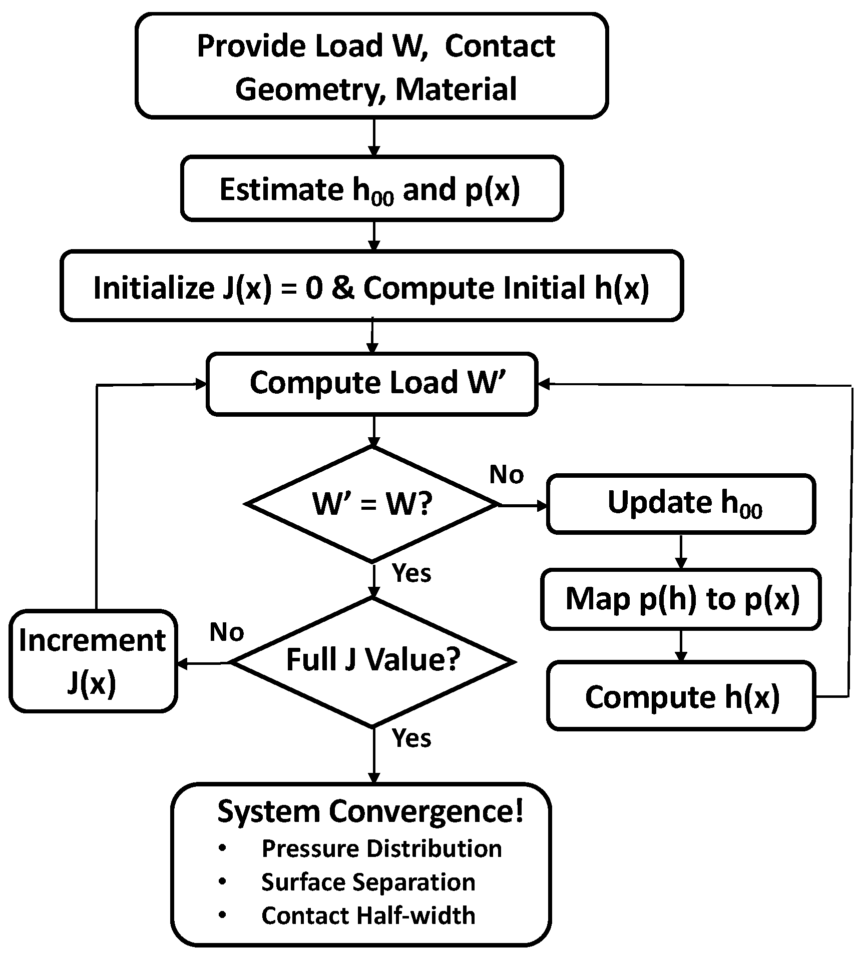
3.2. Application of the Theory to Line Contacts

When considering the contact of two rough curved surfaces, accuracy requires a statistical consideration of the asperity layer (via the JG model), as well as the bulk deformation of the material supporting the asperities.
With the contact of two surfaces of different radii, the equivalent rough surface is characterized by an effective asperity surface curvature 1/R (effective radius R), which is a combination of the curvatures of the two rough surfaces, namely,
1 R = 1 R 1 ± 1 R 2
where the “+” sign is used if both the surfaces are convex and the “–” sign is used for a convex surface in a groove (R2 > R1). As applied to the current TPJB study, the minus sign is appropriate, R2 = Rh is the “housing” radius and R1 = Rp is the “pad-back” radius. Equation (6) is also used in the development of the Hertzian theory, and for the purposes of understanding, this equation pertains to a cylinder with an effective radius R contacting a flat, rough plane (see Figure 3).
Including both the curvature and bulk deformation arising from the distribution of the contact pressures gives an equation for the mean separation,
h x = h 00 + x 2 2 R 2 π E J x
where J x = p s ln x s d s , h00 is a constant to be determined and x is the coordinate perpendicular to the contact line, with its origin at the apex of the contact (see Figure 3). The integral J(x) is based on a line load applying pressure to an elastic half space [23].
The force balance must also be satisfied, viz,
W = 2 L 0 p x d x
where W is the applied load, L is the contact length, and the pressure distribution is assumed to be symmetrical about the contact line. Via the iteration process, this force balance will help to identify the constant h00.
In Figure 3, δ is the relative motion of the approach along the loading axis of two points, one on each body, with both being remote from the contact zone. This value is termed the “compliance”, and will be used during the numerical computation of the stiffness.
For convenience in the comparison and presentation of the results, it is desirable to nondimensionalize these equations using the related Hertzian parameters. W ¯ is the dimensionless load, pH is the peak Hertzian pressure, and xH is the Hertzian contact half-width.
W ¯ = W R L E ,   p H = E W ¯ π ,   x H = 4 W ¯ R 2 π
with these definitions, the dimensionless pressure will always be less than 1 and the dimensionless contact half-width will always be greater than 1. The other required dimensionless parameters are,
h ¯ = h / R , σ ¯ = σ / R , β ¯ = β / R , η ¯ = η R 2
Employing these parameter modifications results in a non-dimensional set of equations that define the system to be solved for the cylindrical contact problem as follows,
p ¯ ( h ¯ ) = p ( h ) / p H = η ¯ β ¯ σ ¯ Φ ¯ ( h ¯ )
h ¯ X = h ¯ 00 + 4 W ¯ π X 2 2 1 π p ¯ s ln X s d s
π 4 = 0 p ¯ X d X
The function Φ ¯ ( h ¯ ) is a non-dimensional form of Φ h , which can be found in [20]. The X coordinate used in these equations is nondimensionalized using the Hertzian half-width, i.e., X = x/xH.
This system of Equations (9)–(11) can be discretized and solved for the pressure distribution using an iterative numerical scheme. The dimensionless surface separation at point i along the X axis is given by,
h ¯ i = h ¯ 00 + 4 W ¯ π X i 2 2 1 π j = N N M i j p ¯ j Δ X
where ∆X are equally spaced increments and Mij is determined from multilevel solution techniques [21,23] shown as,
M i j = i j + 1 2 ln i j + 1 2 X 1 i j 1 2 ln i j 1 2 X 1
The load equilibrium is assured by satisfying,
π 4 = k = 1 N D k p ¯ ( X k )
where Dk = (1,4,2,4, …,2,4,1) X /3 are the weights for the integration by Simpson’s Rule.
The full system of equations tends to be ill-conditioned and cannot generally be solved in a few iterations. The principal difficulty lies in the computation of the bulk deformation represented by J(x) in Equation (7) and the sum in Equation (12). If the cylinder is initially set to be rigid (sum term = 0) but with rough surface, the system solves readily. In the approach used here, this is the starting point, and the first solution can be found by giving estimates for h00 and the pressure distribution. The next iteration starts with the results of the first iteration, but selects a proportion of the sum term in (12) and finds a new pressure solution. This procedure is followed until the full value of the sum term has been applied and the convergence for J(x) has been attained. A flowchart for this procedure is provided in Figure 4. It is straightforward to compute the compliance from the results for the pressure distribution (see Equation (17)).
The pivot stiffness determination for a TPJB pad first requires knowledge of the compliance or relative deformation between the two bodies. The results from a solution of the subject system provide the statistical pressure distribution and extent of the contact half-width. These results are essential for the compliance calculation, and a comparison indicating a partial validation for the pressures and the contact half-width is shown in Figure 5. Both axes are normalized relative to the Hertzian result.
The surface parameters used for this comparison are displayed in Table 1 for the rough surface no. 4, and the two loads are 500 N and 5000 N. The material is steel at room temperature with a 460 MPa yield stress. The effective radius is 20 mm with a 45 mm length. The current results are shown relative to the approximate curve-fitted results from the BK theory of [21], and to the Hertzian results (used for normalization). This plot shows the relative increase in the pressures as the load is increased and the relative reduction in the contact width with an increased load, both trending toward the Hertzian distribution as a high-load limit. The influence of smoothing the surface is similar to the load-increasing behavior.

3.3. Contact Compliance and Stiffness

The computation for the change in the center distances for a loaded cylinder in a groove, based upon the Hertzian theory, is given by Roark [4] for two contacting bodies of the same material (E = E1 = E2). Some algebraic manipulation simplifies the Hertz deflection equation in Roark to be the following,
δ H = 2 W 1 ν 2 π L E 2 3 + l n 1.731 E L ( R 2 R 1 ) W
A Hertzian-type formula for the related contact stiffness is found, firstly, by the differentiation of Equation (14) with respect to load W, and by then taking the inverse, giving the result,
K H = π L E 2 1 ν 2 1 3 + ln 1.731 E L ( R 2 R 1 ) W 1
The computation of the rough surface stiffness based on the JG model must begin with a displacement determination δ for a given load W (see Figure 3). An accurate numerical result for the stiffness determined at load Wi can then be found using a central difference formula, namely,
K p i = W i + 1 W i 1 δ i + 1 δ i 1
where Wi−1 and Wi+1 are the load applications, each separated from Wi by a small load step ∆W, with related displacement values δ.
The computed surface separation values h(x) of Equation (7) cannot be used directly to determine the gross movement of the two cylindrical bodies under a load. However, at the edge of the contact area, at a position x = xE, the asperity deformation becomes nearly zero and the total relative deformation between the bodies can be expressed as the following [19],
δ = x E 2 2 R + 2 π E x E x E p s ln x E s d s
This result includes only the initial geometry and bulk deformation influences, and is further discussed by Beheshti and Khonsari [24]. Unlike the integral of Equation (7), this integral can be numerically integrated directly because the computed pressures are known. Since the integral limits ideally extend to infinity, the choice for the position xE is practically selected for a normalized pressure p ¯ that has become very small, here chosen consistently as 0.001.

3.4. Surface Parameter Identification

As opposed to the nanoscale measurements used by physicists, surface measurement techniques based on mechanical or optical methods are generally sufficient for the development of the set of parameters required for the definition of most manufactured surfaces. However, though accepted and often experimentally qualified for use in current rough surface analyses, the three parameters required to approximately define the topology of a rough surface (σ, β, and η) are not generally available in the common literature.
Surface roughness most commonly refers to the variations in the height of a surface relative to a reference plane. The most often used and measured surface height parameter is Ra, defined as the average absolute deviation of a profile height from its mean line. The value of Ra is an official standard in most industrialized countries and has the relationship σ ≈ π / 2 Ra for Gaussian surfaces. In many cases, σ and Ra are interchangeable.
McCool [25] provides a method for establishing the three required contact parameters (σ, β, and η) by a determination of the surface’s “spectral moments”, which are derivable from measurements. A more detailed discussion related to surface finish can be found in [26,27].
Most practical contact situations do not involve a single rough surface pressing against a smooth surface; usually, the contact is with both surfaces being rough. The equivalent two-surface values for σ, β, and η can be found from the following equations [21],
σ e q = σ 1 2 + σ 2 2
1 β e q = 1 β 1 2 + 1 β 2 2
1 η e q = 1 η 1 β e q β 1 2 + 1 η 2 β e q β 2 2
These expressions are used to define the pivot contact conditions considered in the next section.
For use in this study, four “rough” surfaces with related parameters were selected from the literature and are shown in Table 1. The “smooth” to “rough” ranking is arbitrary and is used only as a relative designation. The surface no. 1 may be roughly representative of a grinding operation, while surface no. 3 could represent a milled or broached finish [25].

4. Comparison to Experiment

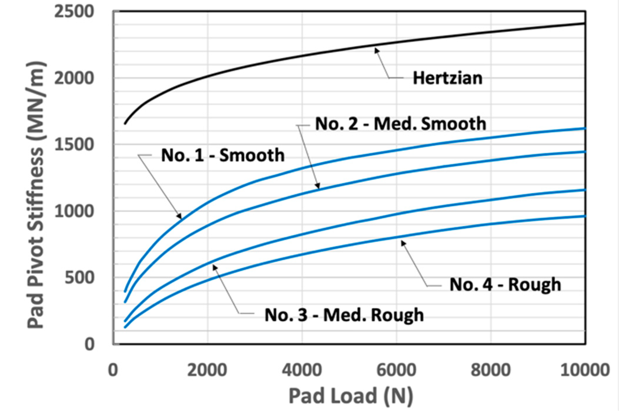
4.1. Individual Pad Pivot Stiffness

All of the previous discussion has focused on the pivot flexibility of individual bearing pads. The dynamic performance of a complete TPJB requires a consideration of the assembly of these pads, each with different conditions of loading. Each bearing pad must generally support a different load, and since the pivot flexibility has a dependency on the pad load, the pivot stiffness will be different for each pad. The aim of this comparison is to show that the inclusion of pivot flexibility due to surface roughness improves the computational results, relative to the Hertzian contact theory, and in fact gives results that compare well with the experimental results for the bearing dynamic properties.
Kulhanek and Childs [28] presented an experimental investigation to measure the dynamic coefficients of a five-pad, load-between-pads TPJB, with an interest in both the static and frequency dependent properties. It is clear and in fact noted in the study that the measured results must include pivot flexibility. Many of the results from this study are tabulated in the Kulhanek thesis [29], which is conveniently accessible for the current work. It was stated by Wilkes and Childs [11] that the method given by Kulhanek provided 95% confidence bounds for the measured bearing impedances.
The bearing under consideration has a diameter of 101.6 mm, an aspect ratio (L/D) of 0.6, central pivots, a machined (cold) pad clearance of 112 μm, a relatively small preload ratio of 0.27, and ISO VG32 oil as its lubricant, supplied at 44 °C. Each pad has a mass of 0.44 kg and a mass moment of inertia about the pivot of 273.9 kg-mm2. Detailed pivot characteristics were not included in either of the references. However, a photo of the bearing pad and pivot region is shown in the Kulhanek thesis [29], permitting an estimation of some geometric details of the pivot.
The pivot used for this bearing is of cylindrical form and is assumed to have the same length as the bearing pad. The “cylinder” sits in a groove that appears to be only slightly larger in radius. The pivot cylinder radius is scaled (very roughly) as 20 mm and the groove radius is taken as 23 mm. The assumed material is the same steel for both the contacting surfaces, with a Poisson’s ratio of 0.29, a yield stress of 360 MPa, and an elastic modulus of 190 GPa (slightly reduced from the room temperature value for the operating temperature).
Using the estimated pivot data in Equation (15), the Hertzian pivot stiffness data, as a function of the pad load, were computed with the results shown in Figure 6. Additionally, shown using Equation (16) are the numerical results of the BK extended formulation for the four surfaces in Table 1. This plot clearly displays the inadequacy of the Hertz formulation, especially for lower loads, which show one third the stiffness relative to the Hertz result.
The particular bearing chosen here was also considered in the work of Wagner and Allaire [15]. In that study, a rotational speed of 7000 rpm with a specific load (W/LD) of 1.723 MPa were used to estimate the magnitude of the pivot stiffness via a comparison to the measured data. The load applied to each of the loaded pads was 6500 N and it was estimated that the stiffness of the film for each loaded pad was about 585 MN/m. It was shown that the best match to the measured data was obtained with a pivot stiffness of approximately 2× the film stiffness, or 1170 MN/m. According to Figure 6, this is about one half the Hertzian value and is in the center of the stiffness range for the rough surfaces on the plot.

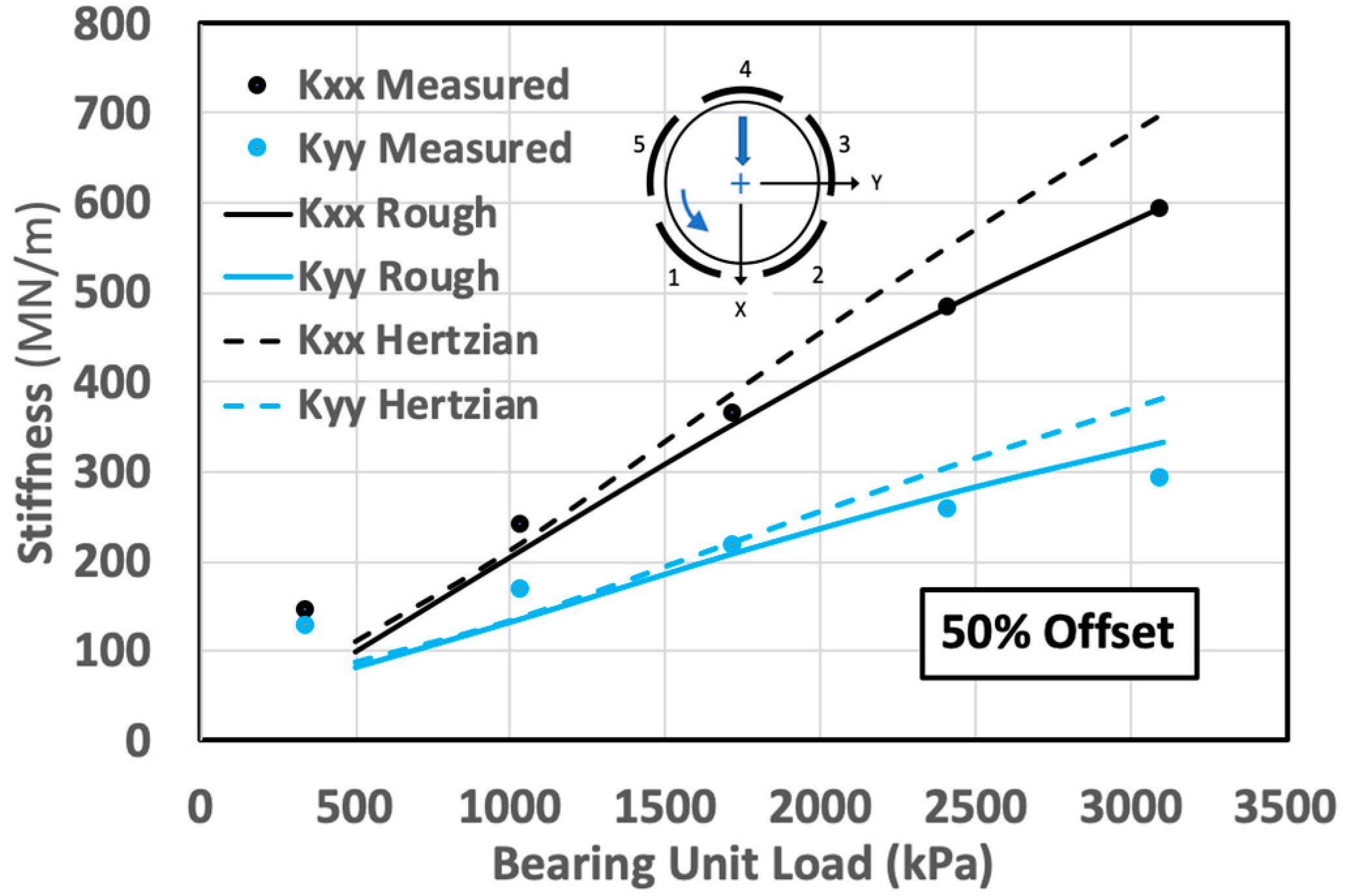
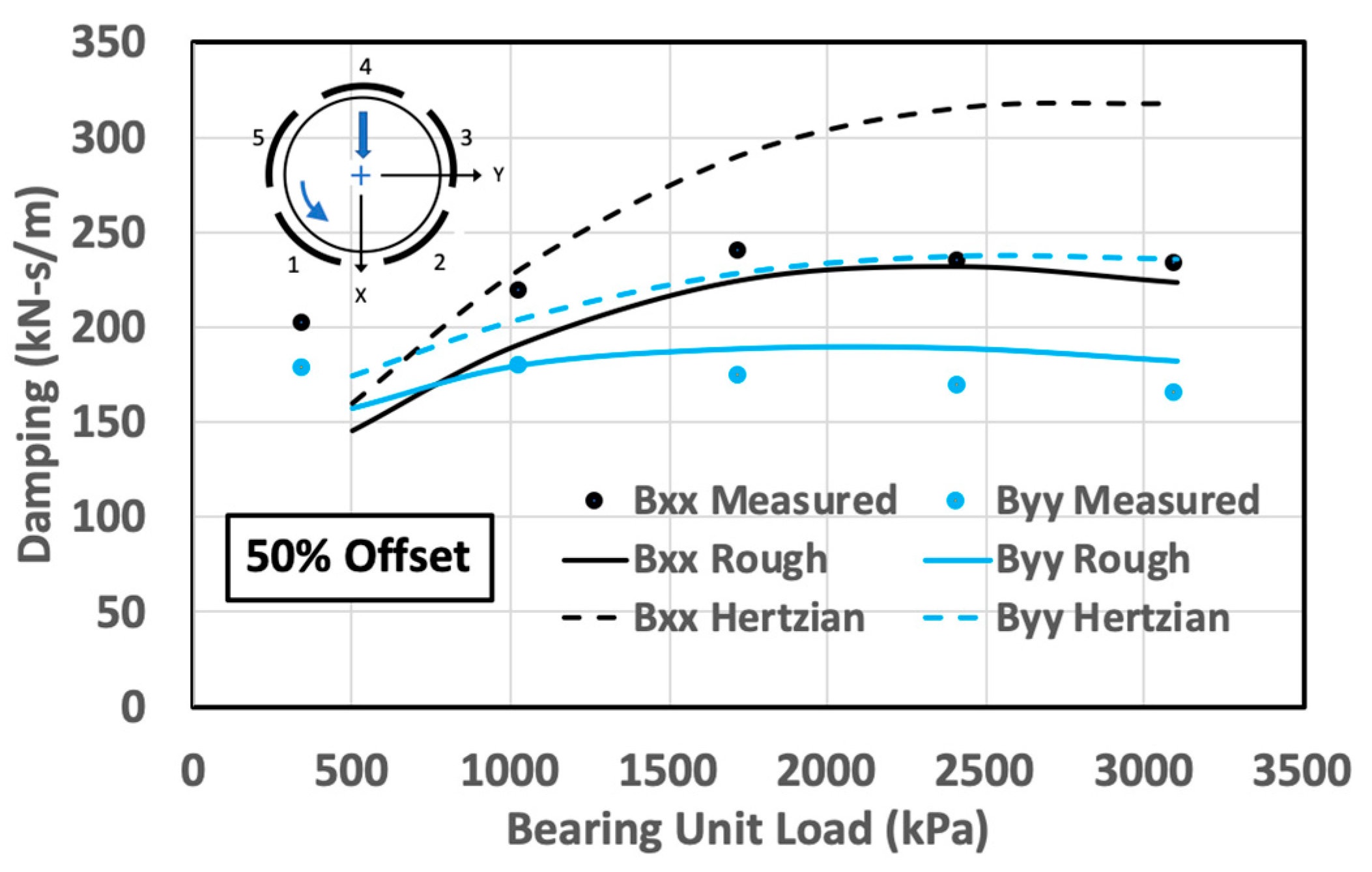
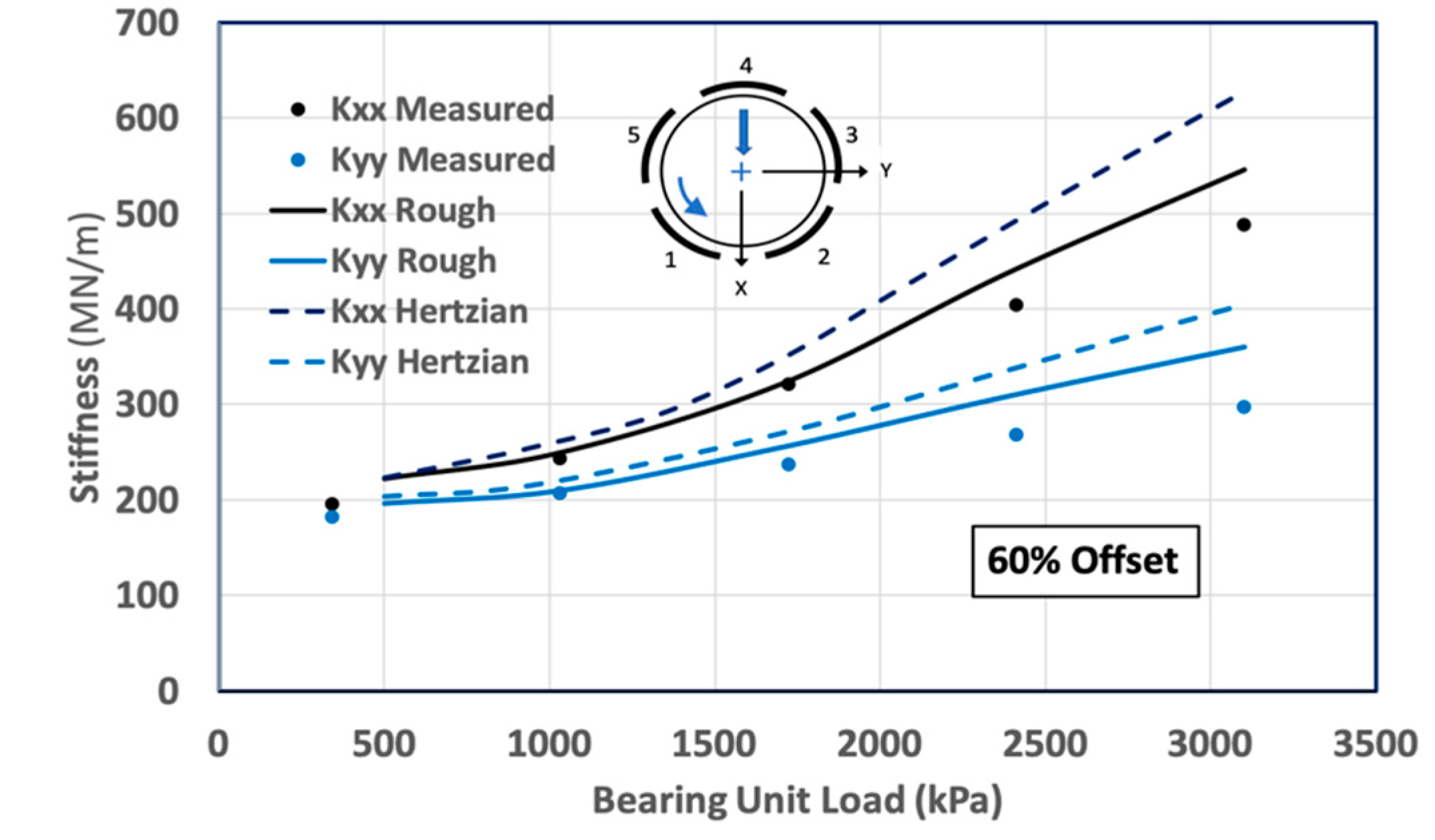
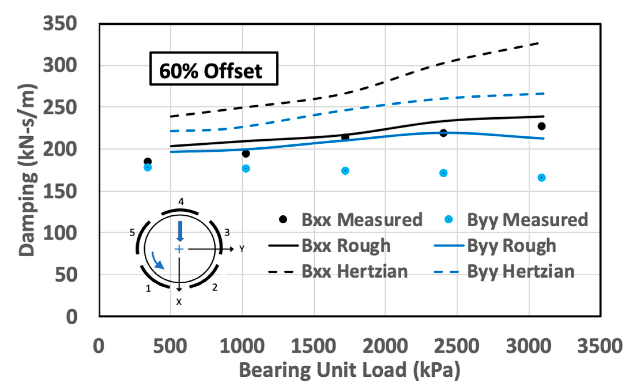
4.2. Complete Bearing Properties

The inclusion of pivot stiffness in TPJB modeling requires an explicit consideration of the parameters governing the dynamics of each individual pad. The pad assembly or KC method would be appropriate for such analyses. The computer code used here is a KC-type code based on a thermohydrodynamic (THD) method developed from the theoretical formulations provided by Suganami and Szeri [30] and the text of Szeri [31], further extended to include a pad radial degree-of-freedom for the consideration of the pivot flexibility [4]. Though undoubtedly of significance at higher speeds and loads, the mechanical and thermal pad bending and growth effects have not been considered.
The mentioned KC-THD code was used to compute the synchronous stiffness and damping coefficients for the subject bearing at both 50% and 60% pivot offsets (“pivot offset” is defined as the circumferential position of the pivot relative to the pad leading edge, divided by the pad’s total circumferential length (expressed as a percentage)), and with computations at a rotational speed of 7000 rpm over a range of representative bearing loads. Although results for other speeds can be presented, the intent here is not to provide data for the design, but to illustrate the impact of a significant effect that has not been previously considered. Furthermore, computations at higher speeds would not be as accurate, since changes in the clearances and effective preloads due to more pronounced thermal effects could not be considered.
No information was presented in the Kulhanek thesis [29] regarding the roughness state of the pivot contacting surfaces. After surveying the full bearing dynamic coefficient results, using the four surfaces identified in Table 1, it was found that surface no. 1 provided the results that agreed most closely with the measured data. This surface description, approximately conforming to a surface of medium grind, has been used for all the pads of the subject bearings. Table 2 displays the individual pad loads and related pivot stiffness values (50% pivot offset) for two selected specific loads of the 7000 rpm computations. The pad numbering follows a CCW rotation, and pads 1 and 2 straddle the load line. The bearing coordinate system is right-handed and uses positive X in the direction of the bearing load, as was generally favored by Lund [1].
The computed stiffness and damping coefficients for this bearing are shown in Figure 7, Figure 8, Figure 9 and Figure 10 for both the 50 and 60 percent pivot offset positions. Only the direct coefficient results are shown; the cross-coupled terms are generally small and ignored. The solid lines on these plots apply to the results for the rough surface pivot contact, while the dashed curves refer to the results for the Hertzian contact. The individual plotted points relate to the measured and tabulated impedance results from [29]. The pad numbering scheme is shown on the plots.
The stiffness results shown in the plots are the real values of the frequency-dependent complex impedance, as evaluated at the rotational frequency Ω. These stiffness coefficients are defined differently to those obtained from the curve fits to the impedance functions, as used by proponents of the KCM modeling. The KCM fits are based on an approximate Taylor series expansion, and Kulhanek [29] has presented the “stiffness” coefficients kt as the constant part of the real impedance, which has been decomposed into a constant term and an Ω2 term with a constant “mass” coefficient mt. The measured points on the stiffness plots in Figure 7 and Figure 9 have been reconstructed as k = kt – mtΩ2, in order to match the original measured impedance real part. The damping coefficients have been determined by dividing the imaginary part of the impedance by Ω.
It is acknowledged that the computed results for the complete TPJB, though reasonably comprehensive, do not consider all of the effects that may have an impact on the results (e.g., the clearance change effects with the temperature and the convective and temporal inertia effects). However, with reference to the effects of the pivot, it is clear from the examples shown that the use of Hertzian pivot stiffness overestimates the complete bearing properties. For these examples, the overestimation is up to 20% for the effective stiffness coefficients and 30% for the effective damping coefficients.

5. Discussion

This study concentrated on cylindrical or rocker-back pivots. However, many bearings used in industry have spherical (also termed “circular”) or elliptical contact areas. For a given load, these contacts function with much higher pressure densities than cylindrical pivots do, thus causing full plastic deformation for many of the asperities. Additionally, a more significant portion of the total contact deformation may be associated with elastic bulk deformation. This situation is thus very similar to elastic Hertzian contact, and this has been noted in the literature [13], where a plot shows a relatively small difference between the measured circular pivot stiffness and the related Hertzian stiffness.
A question comes to mind concerning the paucity of the research related to pivot stiffness. Firstly, this issue is of concern only to those interested in TPJBs, and principally only for dynamic influences. Secondly, many researchers and designers may have considered the “problem solved”, especially after the work of Kirk and Gordon [6], which outlines the Hertzian theory for applications to pivot stiffness. Since many TPJB designs use the spherical pivot design, and the spherical contact stiffnesses are much closer to the Hertzian stiffness results than the line stiffnesses are, the idea that there is no need for further research may be prominent. Finally, it has only been within relatively recent years that experimentalists have begun to realize that measured TPJB dynamic properties are poorly matched with computations, and that this deficiency is likely to be due to the pivot stiffness related to the line contacts [11,12,13,14,15].
A paper of significance for TPJB designers, concerned with modeling circular and elliptical contacts, was published by Beheshti and Khonsari [24]. This is the presentation of a modeling concept for such contacts, along with curve-fitted formulas based on numerical simulations. These formulas can be readily used for the prediction of the maximum contact pressure, contact dimensions, contact compliance, real area of contact, and pressure distribution. Since the formulas give continuous results, it is a simple matter to numerically determine the compliances for the given loads, thus permitting an estimation of the contact stiffness. The same authors presented similar predictive formulas for cylindrical contacts [21], but did not include formulas for compliance. Such equations could be quite useful to bearing designers, and thus be a direction for future work.
In lieu of practical contact stiffness formulas for cylindrical contacts, both this study and that of Dang et al. [13] imply that a reasonable approximation for TPJB line pivot stiffness, one better than Hertzian stiffness, would be to simply use one half of the computed Hertzian value. Such an approximation, though not strongly justified, would be quite useful, particularly to the rotordynamic community.
The results of this study can also be applied to tilting-pad thrust bearings, particularly (but not exclusively) of the equalizing type, and especially if axial dynamics are of concern. Such bearings contain many moving parts, including leveling plates or linkages that are meant to distribute the load equally among the pads. The pad/linkage system is composed of multiple contact points, each having a flexibility affected by the surface’s contact conditions. Just as determined for the TPJB, these contacts may significantly decrease the stiffness of the thrust bearing system for the axial dynamics.

6. Conclusions

The focus of this study was to investigate the pad pivot supports for tilting-pad bearings in response to the recognition by multiple researchers that a pivot may be significantly more flexible than it has been theoretically determined to be. Line or cylindrical pivots were the principal concern. Based on this effort and on the material drawn from related references, the following conclusions have been established.
The conclusions focused on TPJB performance are:
  • The Hertz formula for stiffness, traditionally used for pivot stiffness determinations, has been shown to greatly overestimate pivot stiffness, particularly for line contacts.
  • The computed dynamic coefficient results for a complete TPJB, using rough surface pivot stiffness values, show a significant improvement relative to the results based on the Hertzian pivot stiffnesses.
  • The inclusion of pivot stiffness in TPJB calculations requires a method that considers the individual pad parameters, such as the “pad assembly method” or the “KC method”.
The conclusions related to contact mechanics are:
  • Either an increase in the surface smoothness or an increase in the pad loading will cause an increase in the pivot contact stiffness.
  • All the machined surfaces over the nominal contact area are “rough” on a microscopic scale, such that the actual support area is less than the nominal. This actual contact area is primarily composed of the asperity tips.
  • The deformations causing the pivot flexibility are related to both the asperities and the bulk deformations of the bodies supporting the asperities.
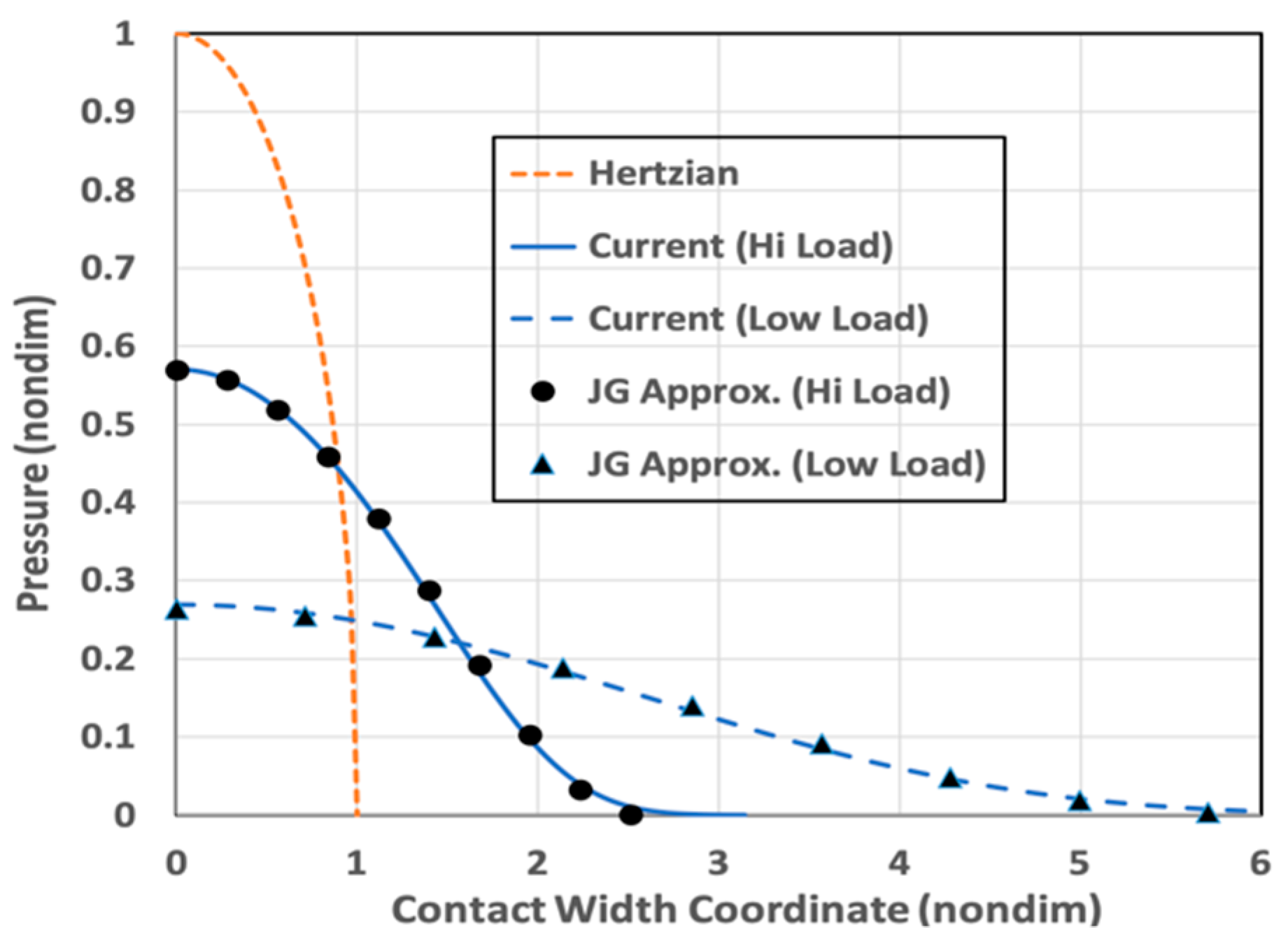
  • The maximum statistical pressure for smooth surfaces is greater than that for rough surfaces, and it is closer to the Hertzian result. This trend also holds as the load is increased. Additionally, the contact area, relative to the Hertzian contact, becomes smaller for smoother surfaces and higher loads.

Funding

This research received no external funding.

Data Availability Statement

Data sharing not applicable.

Conflicts of Interest

The authors declare no conflict of interest.

Nomenclature

BDamping parameter
dSeparation based on asperity heights
DJournal diameter
EMaterial elastic modulus
E’Effective elastic modulus for rough surface contact
hSeparation based on surface heights
h00Constant in separation relationship
KStiffness parameter
JIntegral required for separation computation
KHHertzian contact stiffness parameter
KpStiffness of pad pivot contact
LBearing axial length or length of line contact
pNominal pressure for the contact of two flat surfaces with constant mean separation
pHMaximum Hertzian pressure
REffective radius of curvature
RaAverage absolute deviation of profile heights from the mean line
RpRadius of pad back
RhRadius of pad housing
SyMaterial yield strength
WLoad on bearing
xSpatial coordinate perpendicular to contact line
xESpatial coordinate at boundary of contact region
xHHertzian contact half width
X Dimensionless spatial coordinate (X = x/xH)
ysDistance between the mean of summit heights and that of the surface heights
zasperity height measured from the mean line of summit heights
βAsperity tip radius
βeqEquiv. two-surface asperity tip radius
δCompliance, relative displacement between cylinders
δHHertzian compliance
ηDensity of asperities on surface
ηeqEquiv. two-surface asperity density
νPoisson’s ratio
σStandard deviation of surface heights
σsStandard deviation of summit (asperity) heights
σeqEquiv. two-surface std. dev. of surface heights
φStandard normal distribution function
ΦFunction representing JG micro-asperity contact model
ωAsperity interference
ωcCritical interference according to JG theory
ΩRotational frequency
DOFDegree of freedom
BKBeheshti and Khonsari
JGJackson and Green
KCTPJB model that explicitly includes individual pad DOF
KCMTPJB model that uses constant values of stiffness, damping, and mass for a given operating condition
LBPLoad between pads
LOPLoad on pad
THDThermohydrodynamic
TPJB Tilting-pad journal bearing
Unless otherwise noted, overbar in the text definitions indicates dimensionless parameters.

References

  1. Lund, J.W. Spring and Damping Coefficients for the Tilting-Pad Journal Bearing. ASLE Trans. 1964, 7, 342–352. [Google Scholar] [CrossRef]
  2. Shapiro, W.; Colsher, R. Dynamic Characteristics of Fluid-Film Bearings; Texas A&M University: College Station, TX, USA, 1977; pp. 39–53. [Google Scholar]
  3. Allaire, P.; Parsell, J.; Barrett, L. A pad perturbation method for the dynamic coefficients of tilting-pad journal bearings. Wear 1981, 72, 29–44. [Google Scholar] [CrossRef]
  4. Rouch, K.E. Dynamics of Pivoted-Pad Journal Bearings, Including Pad Translation and Rotation Effects. ASLE Trans. 1983, 26, 102–109. [Google Scholar] [CrossRef]
  5. Young, W.C. Bodies Under Direct Bearing and Shear Stress. In Roark’s Formulas for Stress & Strain, 6th ed.; McGraw-Hill: New York, NY, USA, 1989; pp. 650–651. [Google Scholar]
  6. Kirk, R.G.; Reedy, S.W. Evaluation of Pivot Stiffness for Typical Tilting-Pad Journal Bearing Designs. J. Vib. Acoust. 1988, 110, 165–171. [Google Scholar] [CrossRef]
  7. Pettinato, B.; De Choudhury, P. Test Results of Key and Spherical Pivot Five-Shoe Tilt Pad Journal Bearings Part II: Dynamic Measurements. Tribol. Trans. 1999, 42, 675–680. [Google Scholar] [CrossRef]
  8. Dmochowski, W. Dynamic Properties of Tilting-Pad Journal Bearings: Experimental and Theoretical Investigation of Frequency Effects due to Pivot Flexibility. J. Eng. Gas Turbines Power 2007, 129, 865–869. [Google Scholar] [CrossRef]
  9. Harris, J.; Childs, D.W. Static Performance Characteristics and Rotordynamic Coefficients for a Four-Pad Ball-in-Socket Tilting-Pad Journal Bearing. In Proceedings of the 2008 ASME Turbo Expo, Berlin, Germany, 9–13 June 2008; pp. 1–12. [Google Scholar]
  10. Dimond, T.; Younan, A.; Allaire, P. A Review of Tilting Pad Bearing Theory. Int. J. Rotating Mach. 2011, 2011, 908469. [Google Scholar] [CrossRef]
  11. Wilkes, J.C.; Childs, D.W. Tilting Pad Journal Bearings—A Discussion on Stability Calculation, Frequency Dependence, and Pad and Pivot. J. Eng. Gas Turbines Power 2012, 134, 122508. [Google Scholar] [CrossRef]
  12. San Andrés, L.; Tao, Y. The Role of Pivot Stiffness on the Dynamic Force Coefficients of Tilting Pad Journal Bearings. J. Eng. Gas Turbines Power 2013, 135, 112505. [Google Scholar] [CrossRef]
  13. Dang, P.V.; Chatterton, S.; Pennacchi, P. The Effect of the Pivot Stiffness on the Performances of Five-Pad Tilting Pad Bearings. Lubricants 2019, 7, 61. [Google Scholar] [CrossRef]
  14. Shi, Z.; Jin, Y.; Yuan, X. Influence of pivot design on nonlinear dynamic analysis of vertical and horizontal rotors in tilting pad journal bearings. Tribol. Int. 2019, 140, 105859. [Google Scholar] [CrossRef]
  15. Wagner, L.F.; Allaire, P.E. Tilting-Pad Journal Bearings—Frequency-Dependent Dynamic Coefficients and Pivot Flexibility Effects. Lubricants 2022, 10, 20. [Google Scholar] [CrossRef]
  16. Greenwood, J.A.; Tripp, J.H. The Elastic Contact of Rough Spheres. J. Appl. Mech. 1967, 34, 153–159. [Google Scholar] [CrossRef]
  17. Shi, X.; Polycarpou, A.A. Investigation of Contact Stiffness and Contact Damping for Magnetic Storage Head-Disk Interfaces. J. Tribol. 2008, 130, 021901. [Google Scholar] [CrossRef]
  18. Greenwood, J.A.; Williamson, J.B.P. Contact of nominally flat surfaces. Proc. R. Soc. Lond. Ser. A Math. Phys. Sci. 1966, 295, 300–319. [Google Scholar] [CrossRef]
  19. Kagami, J.; Yamada, K.; Hatazawa, T. Contact width and compliance between cylinders and rough plates. Wear 1986, 113, 353–370. [Google Scholar] [CrossRef]
  20. Jackson, R.L.; Green, I. A statistical model of elasto-plastic asperity contact between rough surfaces. Tribol. Int. 2006, 39, 906–914. [Google Scholar] [CrossRef]
  21. Beheshti, A.; Khonsari, M. Asperity micro-contact models as applied to the deformation of rough line contact. Tribol. Int. 2012, 52, 61–74. [Google Scholar] [CrossRef]
  22. McCool, J.I. Predicting Microfracture in Ceramics Via a Microcontact Model. J. Tribol. 1986, 108, 380–385. [Google Scholar] [CrossRef]
  23. Venner, C.H. Multilevel Solution of the EHL Line and Point Contact Problems. Ph.D. Thesis, Faculty of Engineering Technology, University of Twente, Enschede, The Netherlands, 2022. [Google Scholar] [CrossRef]
  24. Beheshti, A.; Khonsari, M.M. On the Contact of Curved Rough Surfaces: Contact Behavior and Predictive Formulas. J. Appl. Mech. 2014, 81, 111004. [Google Scholar] [CrossRef]
  25. McCool, J.I. Relating Profile Instrument Measurements to the Functional Performance of Rough Surfaces. J. Tribol. 1987, 109, 264–270. [Google Scholar] [CrossRef]
  26. Bhushan, B.; Ko, P.L. Introduction to Tribology, 2nd ed.; John Wiley & Sons: Hoboken, NJ, USA, 2013. [Google Scholar]
  27. ASME B46.1-2019; Surface Texture (Surface Roughness, Waviness, and Lay). American Society of Mechanical Engineers: New York, NY, USA, 2020; 144p.
  28. Kulhanek, C.D.; Childs, D.W. Measured Static and Rotordynamic Coefficient Results for a Rocker- Pivot, Tilting-Pad Bearing with 50 and 60% Offsets. J. Eng. Gas Turbines Power 2012, 134, 052505. [Google Scholar] [CrossRef]
  29. Kulhanek, C.D. Dynamic and Static Characteristics of a Rocker-Pivot, Tilting-Pad Bearing with 50% and 60% Offsets. Master’s Thesis, Texas A&M University, College Station, TX, USA, 2010. [Google Scholar]
  30. Suganami, T.; Szeri, A.Z. A Thermohydrodynamic Analysis of Journal Bearings. J. Lubr. Technol. 1979, 101, 21–27. [Google Scholar] [CrossRef]
  31. Szeri, A.Z. Tribology, Friction, Lubrication and Wear; McGraw-Hill: New York, NY, USA, 1980. [Google Scholar]
Figure 1. Contact region of a TPJB Pad.
Lubricants 11 00189 g001
Figure 2. Geometry of contacting rough surfaces.
Lubricants 11 00189 g002
Figure 3. Cylinder contacting rough surface.
Lubricants 11 00189 g003
Figure 4. Solution process for contact pressure, separation, and area.
Lubricants 11 00189 g004
Figure 5. Distribution of contact pressure.
Lubricants 11 00189 g005
Figure 6. Pad pivot stiffness vs. load.
Lubricants 11 00189 g006
Figure 7. Effect of rough pivot contact—computed vs. measured stiffness coefficients for a full bearing—50% pivot offset.
Lubricants 11 00189 g007
Figure 8. Effect of rough pivot contact—computed vs. measured damping coefficients for a full bearing—50% pivot offset.
Lubricants 11 00189 g008
Figure 9. Effect of rough pivot contact—computed vs. measured stiffness coefficients for a full bearing—60% pivot offset.
Lubricants 11 00189 g009
Figure 10. Effect of rough pivot contact—computed vs. measured damping coefficients for a full bearing—60% pivot offset.
Lubricants 11 00189 g010
Table 1. Selected surface parameters.
Surfaceσ (μm)β (μm)η (m−2)Ref.
No. 1—Smooth0.31701.18 × 109[21]
No. 2—Med. Smooth0.45733.32.0 × 109[24]
No. 3—Med. Rough1.0551.15 × 109[21]
No. 4—Rough1.45281.4 × 109[24]
Table 2. Pad loading and pivot stiffness (50% pivot offset).
Bearing Unit Load (kPa)Pad No.Pad Load (N)Pivot Stiffness (MN/m)
1034140401313
242441330
3528618
400
5654686
2413192071595
293931602
3365486
400
5475576
Disclaimer/Publisher’s Note: The statements, opinions and data contained in all publications are solely those of the individual author(s) and contributor(s) and not of MDPI and/or the editor(s). MDPI and/or the editor(s) disclaim responsibility for any injury to people or property resulting from any ideas, methods, instructions or products referred to in the content.

