Abstract
In the manufacturing and assembly of a toroidal drive mechanism, errors have a great influence on the load sharing of the mechanism. In order to improve the load-sharing characteristics of the mechanism, a floating oil film structure system is designed to support the planetary gear and to compensate for inaccuracies in the manufacturing and assembly of the mechanism parts in this paper. The elasticity and hydrodynamic effect of the floating oil film allow the planetary gear to achieve its own small floatation and produce a certain axial displacement, which compensates for the influence of error and achieves load sharing. To examine the effect of the floating oil film structure, the floating oil film bearing is simulated by FLUENT, the characteristics of the floating oil film are analyzed, and the stiffness and damping coefficients of the floating oil film are calculated. In ADAMS, the method of equivalent replacement of the floating oil film with spring damping is adopted to conduct a dynamic analysis on the toroidal drive mechanism with the floating oil film load-sharing structure, and the results show that the system with a floating oil film structure can effectively compensate the influence of errors and improve the uniform load performance.
1. Introduction
The toroidal drive mechanism has a number of planetary gears, a toroidal planetary worm (i.e., center worm), and a ring gear to transfer motion and power by meshing, so it has achieved a “power split”. In a toroidal planetary worm drive, the surface of the worm and worm wheel is a kind of space meshing surface, a ruled surface and is developable. This mechanism has the characteristics of a large bearing capacity, high transmission efficiency, large transmission ratio, and compact structure, and is a new type of transmission mechanism with good transmission performance [1]. However, owing to the complicated transmission structure, the manufacturing of the center worm and ring gear is difficult, and errors in processing and assembly are therefore readily produced. These errors may lead to an unbalanced loading between the planetary gears, resulting in an eccentric load phenomenon and reductions in the transmission performance and service life of the mechanism [2]. Therefore, the addition of an appropriate load-sharing structure can compensate for the influence of errors, solve the problem of uneven load distribution, and play a key role in excellent transmission performance of the toroidal drive mechanism.
In the field of toroidal load sharing, scholars have conducted in-depth theoretical and experimental research on toroidal drive load sharing, and have obtained significant research results [3,4,5]. Boedo [4] focused upon a practical design for big-end connecting rod journal bearings, which allow for rapid prediction of three key tribological performance measures: cyclic minimum film thickness, cyclic average oil flow and cyclic average power loss. Booker [5] presented an approach for simplified analytical, graphical, and numerical solutions to extremely general problems of dynamically loaded bearings. Morris et al. [6] presented the thermo-mixed-hydrodynamics of compression rings and big-end bearings. In addition, a floating oil film can probably influence the dynamic wear or surface interaction mechanisms between workpiece mating parts [7,8], such as floating surface mechanism of action [9,10], dynamic polished wear [7,11,12] or surface treatment with some polishing methods [13,14,15], etc. Thus, in order to improve load-sharing characteristics of the mechanism, a floating oil film load-sharing structure requires further analysis.
In this paper, in order to improve the load-sharing characteristics of the toroidal drive mechanism, a floating oil film structure system is designed to support the planetary gear and to compensate for inaccuracies. The hydrodynamic effect of the floating oil film is used to make the planetary gear shift, compensate for the influence of errors, and achieve the effect of load sharing. To verify the effect of the floating oil film structure, the floating oil film bearing is simulated using FLUENT, and the stiffness and damping coefficients of the floating oil film are calculated. In ADAMS, the method of equivalent replacement of the floating oil film with spring damping is adopted to conduct a dynamic analysis of the toroidal drive mechanism with the floating oil film load-sharing structure, and the effectiveness and feasibility of this structure are verified by comparing the changes in transmission performance of the system over time.
2. Planetary Gear Supports with Load-Sharing Structure
2.1. Introduction to Toroidal Drive Mechanism
Figure 1 shows a toroidal drive retarder, which is mainly composed of a center worm, planetary gears, planetary frame, ring gear, and cylindrical rollers. The center worm is for power input, and a number of free-rolling cylindrical rollers are evenly distributed on the planetary gear; the cylindrical rollers mesh with the center worm and ring gear, respectively, to achieve rotation. When the ring gear is fixed as the frame, the planetary gear rotates while driving the revolution of the planetary frame, and finally the planetary frame outputs motion and power [16]. The mechanism adopts the form of a spatial pure-rolling drive with multiple cylindrical rollers participating in the driving motion and power, which is a new and efficient driving structure [17].
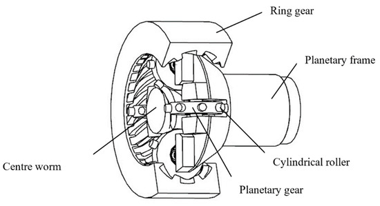
Figure 1.
Diagram of toroidal drive retarder.
2.2. Design of Floating Oil Film Load-Sharing Structure
Referring to the design of a hybrid sliding bearing [18], the purpose of the floating oil film load-sharing structure is to serve as an intermediate ring between the planetary gear and the outer ring (or shaft) of the planetary gear bearing. A certain radial clearance is left between the intermediate ring and the inner hole of the planetary gear, and oil is supplied to the clearance through the oil duct. During the transmission process, the planetary gear drives the lubricating oil into the gap to rotate in the same direction and at the same speed, and the planetary gear and lubricating oil bear the load in the same direction. A thick oil film is then formed, a hydrodynamic effect is produced, and load sharing of the planetary gear is achieved, as shown in Figure 2.
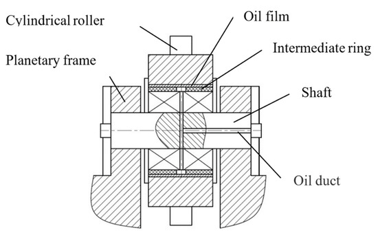
Figure 2.
Floating oil film load-sharing structure of planetary gear.
The main parameters of intermediate ring of the planetary gear are listed in Table 1.

Table 1.
Design parameters of intermediate ring.
Figure 3 shows the center displacement track of the planetary gear. The oil film formed between the intermediate ring and the planetary gear in the rotation of the planetary gear. When the planetary gear is overloaded, the thickness of the oil film decreases and the oil wedge angle also decreases; under a light load, the thickness of the oil film increases proportionally and the oil wedge angle also increases accordingly. In other words, each planetary gear produces different displacements of the planetary gear shaft to adjust the load and achieve load sharing. In other load-sharing methods, the elastic characteristics of the components are affected by the load of the planetary gear, the relative stiffness of the elastic components is larger, and the effect of damping is smaller; deformation then readily leads to fatigue wear, reducing the service life [19]. The floating oil film load-sharing structure uses the stiffness and damping effect of the oil film, is independent of the properties of the component, and can automatically adjust the thickness of the oil film according to load variation to achieve load sharing. At the same time, the oil film has the function of lubrication and damping, which reduces the vibration and friction of the system [20].
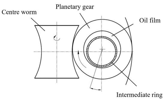
Figure 3.
Centre displacement track of planetary gear.
2.3. Calculation of Floating Oil Film Load-Sharing Coefficient
When the ring gear is fixed, the center worm is connected to the motor to input torque; after the load is applied, the center worm engages with one of the four planetary gears. Manufacturing and assembly errors cause a certain backlash where the other three planetary gears engage with the center worm. When the input torque is further increased, and under the influence of the engaging force, elastic deformation will occur at the support of the cylindrical roller and planetary shaft to compensate for the meshing backlash of the other planetary gears, and the remaining planet gears are in the meshed state [21]. When the center worm meshes with the ith planetary gear (i = 1, 2, 3, 4), the angles created by the elastic deformation are set as θs and θpi, and the following equation for the load on the tooth surface can be obtained:
In Equation (1), Fspi and FpiI are the load on the tooth surface when the ith planetary gear meshes with the center worm and the ring gear, respectively; Kspi and KpiI are the meshing stiffness when the ith planetary gear meshes with the center worm and the ring gear, respectively; rs, rpi and rI are the radius of the center worm, the ith planetary gear and the ring gear; θs, θpi and θI are the angles on the center worm, the ith planetary gear and the ring gear created by the elastic deformation; and Δspi and ΔpiI are the accumulated errors when the ith planetary gear meshes with the center worm and the internal gear ring.
When the ring gear is fixed, θI = 0, and the sum of the two sides of Equation (1) gives us the following for the total load:
According to the power split characteristics of the center worm and planetary gear, input torque T can be obtained:
The theoretical average load of the planetary gear is known to be
At equilibrium, the forces on the planetary gear are balanced,
The load-sharing coefficient refers to the ratio between the maximum load of the planetary gear and the center worm or ring gear and the theoretical average load. The load-sharing coefficient of the planetary gear can be obtained from Equations (1)–(5):
3. Numerical Simulation of Planetary Gear Floating Oil Film
3.1. Establishment and Meshing of Floating Oil Film Model
A three-dimensional (3D) model of the toroidal floating oil film bearing was established with a width to diameter ratio of 0.5, the inside of the floating oil film bearing was a fixed wall surface, the outside was a rotating wall surface, and the bearing had an oil inlet hole at the top. The basic parameters of the floating oil film bearing were as follows: diameter of bearing pad D = 48 mm, bearing width B = 24 mm, oil inlet diameter and height h1 = 0.5 mm, and eccentricity ε = 0.3.
The 3D model of the floating oil film bearing was imported into ANSYS ICEM modelling software using hexahedral mesh for the mesh division; the result is shown in Figure 4. The value of the mesh determinant 2 × 2 × 2 was greater than 0.7 and the internal angle was greater than 18°, which led to a high partition quality and met the requirements of mesh quality [21].
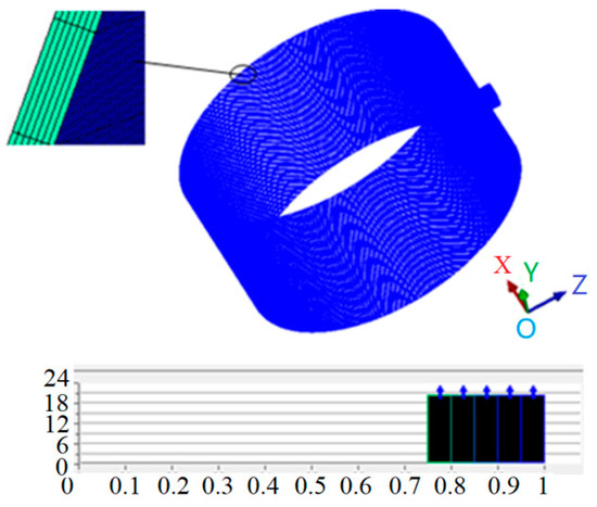
Figure 4.
Overall oil film mesh and quality.
3.2. Steady-State Flow Field Calculation of Floating Oil Film
The steady-state flow field of the floating oil film was solved using FLUENT 14.0 software, the SIMPLE algorithm was used as the pressure–velocity coupling algorithm, Presto software was used to interpolate a discrete form of the pressure equation, and a second-order upwind method was used to interpolate a discrete form of the momentum equation [22]. The initial rotation rate of the planetary gear was set to 1000 rpm, the eccentricity was 0.3, and the oil pressure was 0.2 MPa. The resulting pressure contours are shown in Figure 5.
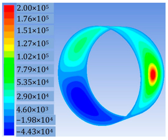
Figure 5.
Pressure contours of floating oil film.
Based on the obtained pressure contours of the floating oil film, the following characteristics of the floating oil film can be obtained:
- The floating oil film structure creates a stable oil pressure. The pressure is highest at the right-side inlet, with a value of 0.2 MPa. The pressures in the upper and lower oil chambers of the inlet gradually decrease, because when the floating oil film bearing operates, it moves down owing to gravity, which leads to a reduction in the oil film clearance of the lower oil chamber and an increase in that of the upper oil chamber. Positive and negative pressure regions are formed, which conform to hydrodynamic principles.
- In the axial direction, because the floating oil film bearing discharges oil at both ends and these ends are at atmospheric pressure, the pressure of the oil film decreases in the axial direction and is at atmospheric pressure at the boundary.
- In the circumferential direction, the oil film rotates in the same direction as the planetary gear, and the lubricating oil is throughout the entire clearance. When the lubricating oil moves from the oil inlet into the oil cavity, the pressure is at a maximum. With the rotation of the planet gear, the pressure of the oil film gradually decreases axially along the neck surface until the negative pressure zone is burst; the supply of lubricating oil then continues and a new pressure distribution of the oil film develops.
3.3. Force Field Characteristic Analysis of Floating Oil Film
The pressure and bearing capacity are the key characteristic parameters of the floating oil film and determine the resistance of the planetary gear to external load, that is, the effectiveness of the floating oil film load-sharing structure [23]. The pressure and bearing capacity of the floating oil film are influenced by the design parameters, the working conditions, and many other factors, among which eccentricity is one of the most important; the eccentricity is therefore selected in this analysis as the main factor influencing the floating oil film. Owing to the eccentricity, the state of the floating oil film in each direction will change, producing new dynamic characteristics. However, an excessive eccentricity will produce strong hydrodynamic effects, and the lubricating oil in the clearances will be prone to backflow, which may cause the rupture of the oil film [24]. Therefore, the influence of eccentricity between 0.3 and 0.6 was first studied, at a rotational speed of 2000 rpm and oil inlet pressure of 0.2 MPa. The pressure distribution of the oil film for different eccentricity s is shown in Figure 6.
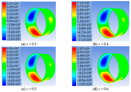
Figure 6.
Pressure distribution of oil film for different eccentricity.
As shown in Figure 6, the pressure of the oil film positive-pressure zone increases with the increasing eccentricity, but the pressure of the oil film negative-pressure zone decreases. This is because, with the increase in eccentricity, the oil film produces a larger wedge clearance, the positive-pressure oil chamber above the oil film increases gradually, the negative-pressure oil chamber under the oil film decreases gradually, the oil film is significantly squeezed, the hydrodynamic effect is more pronounced, and the pressure of the oil film increases.
As indicated in Table 2, the bearing capacity of the oil film increases with increasing eccentricity. When the eccentricity increases, the wedge angle between the clearances then increases, the squeezing action of the oil film intensifies, and the maximum pressure of the oil film increases, such that the oil film can bear more load.
Table 2.
Bearing capacity of oil film for different eccentricity.
In the design of the floating oil film load-sharing structure, the eccentricity should therefore be increased appropriately, because that can improve the pressure and the bearing capacity of the floating oil film and enhance the resistance of the planetary gear to external loads. However, too large an eccentricity will cause oil backflow. The pressure and temperature of the oil film should also be controlled to avoid rupture of the oil film caused by excessive pressure and temperature.
3.4. Calculation of Equivalent Stiffness and Damping of Floating Oil Film
3.4.1. Difference Calculation Model of Stiffness and Damping
When the oil film bearing is disturbed by displacement or velocity in the static equilibrium position, the reaction force by the oil film on the shaft neck will change [25]. When the disturbance is small and with a small amplitude, the relationship can be regarded as linear and the oil film can be regarded as having linearized stiffness and damping, as shown in Figure 7.
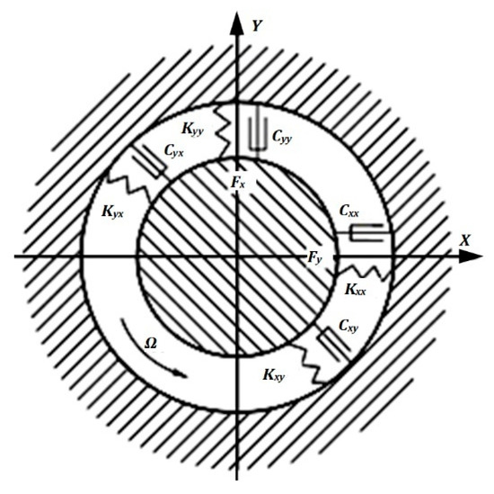
Figure 7.
Linearized floating oil film mechanical model.
Expanding the oil film force as a Taylor series and retaining the linear term, we obtain
The oil film force is approximated as a linear function of the minute displacement and velocity of the shaft neck. In Equation (7), the subscript 0 indicates that the derivative is taken at the static equilibrium position. The oil film force increment caused by the disturbance displacement is defined as the stiffness coefficient of the oil film, that is,
The oil film force increment caused by the speed displacement is defined as the damping coefficient of the oil film, that is,
In the formulae, the first subscript represents the direction of the force, and the second represents the direction of the displacement or velocity. Thus, the dynamic characteristics of the oil film depend directly on the disturbance pressure.
3.4.2. Calculation of Stiffness and Damping of Floating Oil Film
A disturbance velocity of v = 25 μm/s and disturbance displacement of s = 25 μm was applied to the floating oil film bearing, the planetary gear rotational speed was set to 1000 rpm, and the oil inlet pressure was set to 0.2 MPa. The oil film force before and after the disturbance was calculated by FLUENT post-processing, and the stiffness and damping coefficients of the oil film were calculated by substituting the oil film force into Equations (8) and (9). The coefficients are listed in Table 3.
Table 3.
Stiffness and damping coefficients of floating oil film.
4. Discussion
4.1. Establishment of Floating Oil Film Rotor Model
Considering the complexity of the toroidal drive mechanism model [2], the 3D model was first established using the 3D software UG, and the exported Parasolid file was imported into ADAMS to establish the simulation model. The established virtual prototype model is shown in Figure 8, which is mainly composed of a center worm, planetary gears, planetary frame and ring gear. The joints and constraints between parts are shown in Table 4.
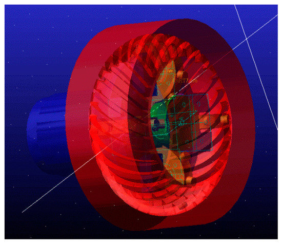
Figure 8.
Virtual prototype model.
Table 4.
Joints and constraints between parts.
Referring to the linearized floating oil film mechanical model, the floating oil film was modelled as an equivalent spring; circumferentially, the floating oil film was equivalent to four rotating spring dampers, as shown in Figure 9. As shown in Table 3, the spring attribute parameters were input into the model to complete the rotor dynamics simulation model. The center worm rotational speed is equal to 2000 rpm and the transmission power is 8 Kw.
Figure 9.
Equivalent spring model of floating oil film.
4.2. Analysis of Dynamic Simulation Results
To verify the effectiveness of the floating oil film load-sharing structure and analyze the influence of the structure on the transmission performance of the mechanism, the ADAMS simulation data with and without the load-sharing structures of the toroidal drive mechanism were compared. We set the input speed of the central worm as 2000 rpm and the transmission power as 8 kw for simulation analysis.
4.2.1. Analysis of Planetary Gear Speed
Figure 10 shows the change diagram of the angular velocity of planetary gear 1 in the toroidal drive mechanism without and with the floating oil film load-sharing structure. Figure 10 indicates that the fluctuation of the angular velocity of the planetary gear with the load-sharing structure is smaller than without. The oil film therefore has a certain buffering and damping effect on the system; it can balance the load, stabilize the transmission, and reduce the planetary gear velocity mutation, therefore improving the load-sharing performance of the system. The change diagrams of the angular velocity of other planetary gears are similar to that of planetary gear 1, with only small differences in values, and therefore they require no elaboration.
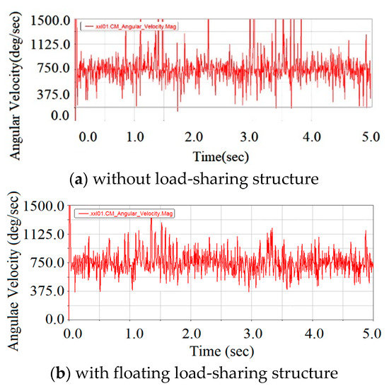
Figure 10.
Comparison of angular velocity of planetary gear 1.
Figure 11 shows the change diagram of angular velocity of the planetary frame in the toroidal drive mechanism without and with the floating oil film load-sharing structure. The diagram indicates that the angular velocity of the planetary frame with the load-sharing structure has a smaller fluctuation range and the output speed of the system is more stable. This indicates that the floating oil film load-sharing structure can effectively improve the transmission stability of the system and is conducive to a stable output power of the mechanism.
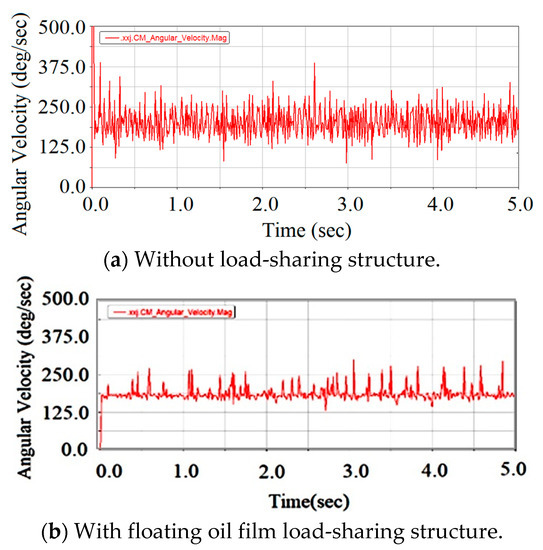
Figure 11.
Comparison of angular velocity of planetary frame.
4.2.2. Analysis of Planetary Gear Engaging Force
Two of the four planetary gears were compared to observe the changes in the engaging force. Figure 12 shows the engaging force changes between the planetary gear and the center worm in the toroidal drive mechanism without and with the floating oil film load-sharing structure. As indicated in the figure, owing to systematic errors and other factors, the engaging forces of the two planetary gears vary in different manners, and unbalanced loading occurs. The engaging force of each planetary gear without the load-sharing structure fluctuates significantly over time, which is not conducive to an even and stable load transfer for the planetary gear. However, after the floating oil film load-sharing structure is adopted, the engaging force of each planetary gear decreases with time, the fluctuation amplitude of the engaging force decreases, and the eccentric loading of the planetary gear decreases, except for the sudden change of load when a few rollers are engaging in and engaging out. This indicates that the floating oil film load-sharing structure has a certain effect on the load sharing of the planetary gear that is conducive to even load transfer and a more stable system drive.
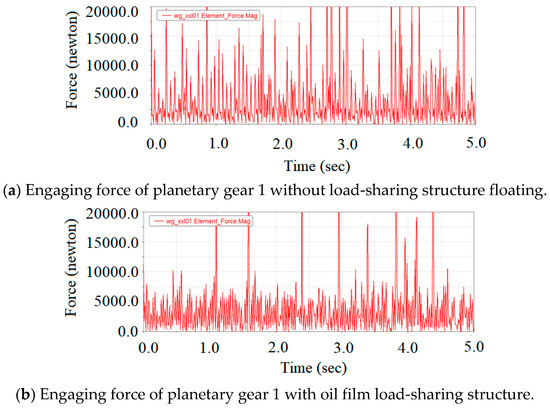
Figure 12.
Comparison of engaging force of planetary gear and center worm.
Table 5 shows a comparison of the mean value of the external engaging force without and with the floating oil film load-sharing structure. The external engaging forces of the mechanism with the load-sharing structure are similar and relatively concentrated, indicating that the mechanism with the floating oil film load-sharing structure can achieve load sharing.
Table 5.
Comparison of mean value of external engaging force without and with floating oil film load-sharing structure.
Figure 13 shows comparison diagrams of the forces acting on the planetary gear and the ring gear in the toroidal drive mechanism without and with the floating oil film load-sharing structure. As indicated in the figure, after the floating oil film load-sharing structure is adopted, the fluctuation range of the engaging force between the planetary gear and the ring gear decreases, and the planetary gear can adjust the meshing position with the ring gear, which compensates for the influence of the machining and assembly errors of the planetary gear on the driving and meshing and improves the system load-sharing performance.
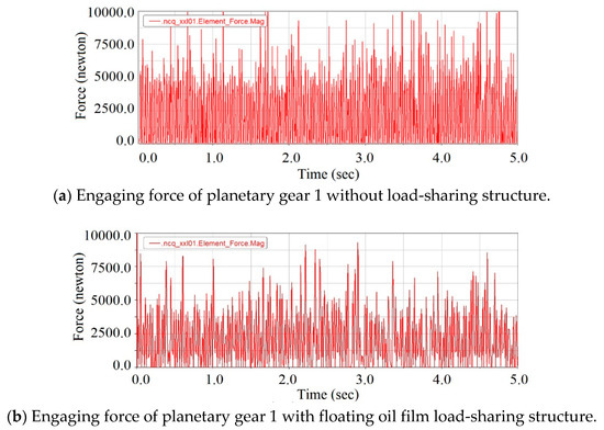
Figure 13.
Comparison of engaging force of planetary gear and ring gear.
Table 6 shows a comparison of the mean value of the internal engaging forces between the planetary gear and ring gear in the toroidal drive mechanism without and with the floating oil film load-sharing structure. The transmission load of the mechanism with the load-sharing structure tends to be balanced; in contrast, without the load-sharing structure, the force of the planetary gear in the toroidal drive mechanism is either too large or too small.
Table 6.
Comparison of mean value of internal engaging force without and with floating oil film load-sharing structure.
4.2.3. Analysis of Planetary Gear Axial Displacement
The axial motion of the planetary gear was simulated using ADAMS. Figure 14 shows the center displacement diagram of planetary gear 1 in the toroidal drive mechanism with the floating oil film structure. The center displacement diagrams of other planetary gears are similar to that of planetary gear 1, with only small numerical differences. As indicated in the figure, when the mechanism runs under stable working conditions, the floating oil film produces a hydrodynamic effect that allows the planetary gear to resist the external load. The axis of the planetary gear moves above and below the center position approximately 0.06 mm in the x and y directions, which plays a role in adjusting the meshing position and the loading of the planetary gear, effectively compensating for the influence of error, balancing the load, and achieving load sharing.
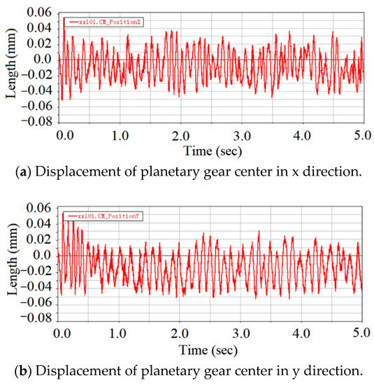
Figure 14.
Centre displacement as a function of time.
4.3. Dynamic Force Analysis of Floating Oil Film
Figure 15 shows the change in the equivalent oil film force of planetary gear 1 in the transmission process. The changes for other planetary gears are similar to that of planetary gear 1 with only small differences in value, and therefore do not require an explanation.
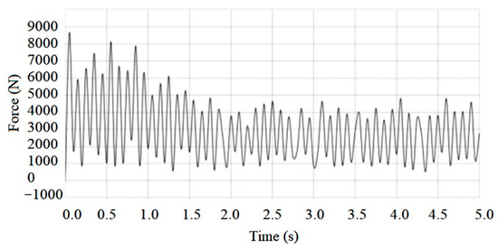
Figure 15.
Change in equivalent oil film force of planetary gear 1.
Figure 15 shows that, in the initial stage, the speed of the planet gear is low, the transmission is not stable, and the bearing capacity of the oil film fluctuates significantly. As the planetary gear speed improves, the system runs in a stable manner, and the fluctuation in the bearing capacity of the oil film is reduced. When the system reaches a stable operating condition, the floating oil film forms a stable hydrodynamic effect and stable bearing capacity controlled at 3 KN, which is greater than the average load of the planetary gears in Table 4 and Table 5. Therefore, the oil film structure can withstand the impact of the load in the operating range, assist the planetary gear in resisting the displacement of the center caused by external loads, allow the position of the meshing point of the planetary gear with the center worm and ring gear to adjust by itself, compensate for the influence of machining and assembly errors on the load transmission, and achieve a load-sharing effect. Theoretically, the floating oil film will generate the dynamic wear or surface interaction mechanisms between workpiece mating parts [7,8], such as the dynamic polished wear and floating surface mechanism of action [26,27].
4.4. Analysis of Dynamic Load-Sharing Performance of Floating Oil Film
The load-sharing coefficient is an index to evaluate the load-sharing performance of the system. The closer the coefficient value is to 1, the better the load-sharing performance. With the data of the planetary gear force extracted from ADAMS, the load-sharing coefficient solved using MATLAB, and data fitting performed using Equation (6), the curves of the load-sharing coefficient of the toroidal drive mechanism without and with the floating oil film load-sharing structure over a period of time were obtained, as shown in Figure 16.
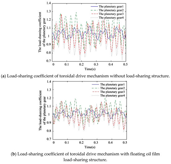
Figure 16.
Load-sharing coefficient of system.
The comparison shows that when the floating oil film load-sharing structure is adopted, the maximum load-sharing coefficient of the system decreases from 1.31 to 1.20, and the minimum load-sharing coefficient increases from 0.72 to 0.83. The system with the floating oil film load-sharing structure has a maximum load-sharing coefficient that is 0.11 lower and a minimum coefficient that is 0.11 higher, and the fluctuation range of the load-sharing coefficient of each planetary gear decreases, and the value of the coefficient is closer to 1. Therefore, the floating oil film load-sharing structure of the planetary gear can adjust the loading situation of each planetary gear, reduce the influence of error on the transmission load, and effectively improve the load-sharing performance of system.
5. Conclusions
- Comparisons of the angular velocity of the planetary gear, the output angular velocity of the planetary frame, and the engaging force of the planetary gear with the center worm and ring gear demonstrate that the transmission performance of the system with the floating oil film structure is improved, the rotations of the planetary gear and the planetary frame are smoother, the fluctuation range and the mutation of the meshing force of the planetary gear decrease, and the load-sharing performance is improved.
- When the center displacement curve of the planetary gear is simulated under stable working conditions, the hydrodynamic effect of the floating oil film produces a floating displacement in the planetary gear of approximately 0.06 mm in the x and y directions to adjust the loading of the planetary gear, effectively compensating for the influence of error and achieving load sharing.
- The simulation and analysis of the bearing capacity of the floating oil film indicate that, after stable operation of the floating oil film, the bearing capacity of the oil film fluctuates at 3 kN, and the planetary gear can resist the central displacement caused by the external load; thus, load sharing is achieved.
- The engaging force of the planet gear was extracted and the load-sharing coefficient of the system with the floating oil film load-sharing structure was calculated using MATLAB. Compared with the system without the load-sharing structure, the system with the floating oil film load-sharing structure has a maximum load-sharing coefficient that is 0.11 lower and a minimum coefficient that is 0.11 higher, the fluctuation of the coefficient is reduced, and the value of the coefficient is closer to 1. These demonstrate that the floating oil film load-sharing structure of the planetary gear is effective and that improving the load-sharing performance of the system is feasible.
Author Contributions
Conceptualization, S.Y., M.M. and M.L.; formal analysis, C.Q.; funding acquisition, M.M. and M.L.; investigation, X.C.; methodology, S.Y.; software, M.D.; writing—original draft, X.L. and M.M.; writing—review and editing, M.L. All authors have read and agreed to the published version of the manuscript.
Funding
This research was funded by Natural Science Foundation of Hunan, grant number 2021JJ50125, 2022JJ50133 and 2022JJ50134; Hunan Provincial Key R&D Foundation (2017GK2050).
Data Availability Statement
Not applicable.
Conflicts of Interest
The authors declare no conflict of interest.
Nomenclature
| B | Bearing width (mm) | l | Width of intermediate ring (mm) |
| Cxx | Direct damping coefficient (N·s/mm) | l/D | Width to diameter ratio |
| Cxy | Cross damping coefficient (N·s/mm) | Ra | Surface roughness (μm) |
| Cyy | Direct damping coefficient of oil film (N·s/mm) | rI | Radius of the ring gear (mm) |
| Cyx | Cross damping coefficient of oil film (N·s/mm) | rpi | Radius of the ith planetary gear (mm) |
| D | Inner diameter of intermediate ring (mm) | rs | Radius of the center worm (mm) |
| d | Outer diameter of intermediate ring (mm) | s | Disturbance displacement (μm) |
| Fspi | Load on the tooth surface when ith planetary gear meshes with the center worm (N) | T | Input torque (N·m) |
| FpiI | Load on the tooth surface when the ith planetary gear meshes with the ring gear, respectively (N) | v | Disturbance velocity (μm/s) |
| h1 | oil inlet diameter and height (mm) | ε | Eccentricity |
| Kxx | Direct stiffness coefficient of oil film (N/mm) | θI | Angles on the ring gear created by elastic deformation (o) |
| Kxy | Cross stiffness coefficient of oil film (N/mm) | θpi | Angles on the ith planetary gear (o) |
| Kyy | Direct stiffness coefficient of oil film (N/mm) | θs | Angles on the center worm (o) |
| Kyx | Cross stiffness coefficient of oil film (N/mm) | φ | Radial clearance (mm) |
| Kspi | Meshing stiffness when the ith planetary gear meshes with the center worm (N/mm) | Δspi | Accumulated errors when the ith planetary gear meshes with the center worm |
| KpiI | Meshing stiffness when the ith planetary gear meshes with the ring gear, respectively (N/mm) | ΔpiI | Accumulated errors when the ith planetary gear meshes with the internal gear ring |
References
- Zhao, Y.; Zhao, Z. Computer aided analysis on the meshing behavior of a height-modified dual-torus double-enveloping toroidal worm drive. Comput.-Aided Des. 2010, 42, 1232–1240. [Google Scholar] [CrossRef]
- Montestrue, A.N. A Numerical Approach to Calculation of load Sharing in Planetary Gear Drive. J. Mech. Des. 2010, 132, 014503. [Google Scholar] [CrossRef]
- Singh, A. Load sharing behavior in epicyclic gears: Physical explanation and generalize formulation. Mech. Mach. Theory 2010, 45, 511–530. [Google Scholar] [CrossRef]
- Boedo, S. Practical tribological issues in big-end bearings. In Tribology and Dynamics of Engine and Powertrain (Fundamentals, Applications and Future Trends); Rahnejat, H., Ed.; Woodhead Publishing: Sawston, UK; Rochester Institute of Technology: New York, NY, USA, 2010; pp. 615–634. [Google Scholar]
- Booker, J.F. Dynamically-loaded journal bearings: Numerical application of the mobility method. J. Lubr. Technol. 1971, 93, 168–176. [Google Scholar] [CrossRef]
- Morris, N.; Mohammadpour, M.; Rahmani, R.; Johns-Rahnejat, P.M.; Rahnejat, H.; Dowson, D. Effect of cylinder deactivation on tribological performance of piston compression ring and connecting rod bearing. Tribol. Int. 2018, 120, 243–254. [Google Scholar] [CrossRef]
- Boedo, S.; Blais, T. Revisiting mobility-based predictions of cyclic minimum film thickness in big-end connecting rod bearings. SAE Int. J. Engines 2022, 15, 263–281. [Google Scholar] [CrossRef]
- Eftekhari, M.; Eftekhari, M.; Rahmatabadi, A.D. Stability analysis of rotating shaft under electromagnetic and bearing oil-film forces. Proc. Inst. Mech. Eng. Part K J. Multi-Body Dyn. 2021, 235, 427–442. [Google Scholar] [CrossRef]
- Chouksey, M.; Dutt, J.K.; Modak, S.V. Modal analysis of rotor-shaft system under the influence of rotor-shaft material damping and fluid film forces. Mech. Mach. Theory 2012, 48, 81–93. [Google Scholar] [CrossRef]
- Fan, C.C.; Pan, M.C. Active elimination of oil and dry whips in a rotating machine with an electromagnetic actuator. Int. J. Mech. Sci. 2011, 53, 126–134. [Google Scholar] [CrossRef]
- Holzenkamp, M.; Kolodziej, J.R.; Boedo, S.; Delmotte, S. An experimentally validated model for reciprocating compressor main bearings for applications in health monitoring. In Proceedings of the ASME 2013 Dynamic Systems and Control Conference, Palo Alto, CA, USA, 21–23 October 2013; ASME: New York, NY, USA. [Google Scholar] [CrossRef]
- Li, M.; Song, F.; Huang, Z. Control strategy of machining efficiency and accuracy in weak-chemical-coordinated-thickening polishing (WCCTP) process on spherical curved 9Cr18 components. J. Manuf. Process. 2022, 74, 266–282. [Google Scholar] [CrossRef]
- Li, M.; Xie, J. Green-chemical-jump-thickening polishing for silicon carbide. Ceram. Int. 2022, 48, 1107–1124. [Google Scholar] [CrossRef]
- Li, M.; Karpuschewski, B.; Ohmori, H.; Riemer, O.; Wang, Y.; Dong, T. Adaptive shearing-gradient thickening polishing (AS-GTP) and subsurface damage inhibition. Int. J. Mach. Tools Manuf. 2021, 160, 103651. [Google Scholar] [CrossRef]
- Li, M.; Karpuschewski, B.; Riemer, O. Controllable polishing process for machining of barium borate. CIRP J. Manuf. Sci. Technol. 2022, 37, 291–301. [Google Scholar] [CrossRef]
- Li, S. Effects of machining errors, assembly errors and tooth modifications on loading capacity, load-sharing ratio and transmission error of a pair of spur gears. Mech. Mach. Theory 2007, 42, 698–726. [Google Scholar] [CrossRef]
- Wu, J.L.; Zhang, N. Driving mode shift control for planetary gear based dual motor powertrain in electric vehicles. Mech. Mach. Theory 2021, 158, 104217. [Google Scholar] [CrossRef]
- Wassim, L.; Fathi, D.; Dhouha, T. Dynamic modelling of differential bevel gear system in the presence of a defect. Mech. Mach. Theory 2019, 139, 81–108. [Google Scholar]
- Li, M.; Liu, M.; Riemer, O.; Song, F.; Lyu, B. Anhydrous based shear-thickening polishing of KDP crystal. Chinese J. Aeronaut. 2021, 34, 90–99. [Google Scholar] [CrossRef]
- Zhang, C.P.; Wei, J.; Wang, F.M.; Hou, S.S.; Zhang, A.Q.; Lim, T.C. Dynamic model and load sharing performance of planetary gear system with journal bearing. Mech. Mach. Theory 2020, 151, 103898. [Google Scholar] [CrossRef]
- Yao, L.G.; Dai, J.S.; Wei, G.W.; Li, H.M. Geometric modeling and meshing characteristic of the toroidal drive. ASME J. Mech. Des. 2005, 127, 988–996. [Google Scholar] [CrossRef]
- Divyanshu, P.; Mishra, P.; Banskar, V. Flow simulation of an I.C. engine in FLUENT, ANSYS 14.0. Int. J. Eng. Res. Appl. (IJERA) 2014, 252–255. [Google Scholar]
- Shen, Z.X.; Qiao, B.J.; Yang, L.H.; Luo, W.; Yang, Z.B.; Chen, X.F. Fault mechanism and dynamic modeling of planetary gear with gear wear. Mech. Mach. Theory 2021, 155, 104098. [Google Scholar] [CrossRef]
- Mo, S.; Zhang, T.; Jin, G.G.; Cao, X.L.; Gao, H.J. Analytical investigation on load sharing characteristics of herringbone planetary gear train with flexible support and floating sun gear. Mech. Mach. Theory 2020, 144, 103670. [Google Scholar]
- Li, M.; Shi, T.; Yang, J.G.; Qi, L.H.; Zhao, Z.H. Realizing nonlinear springs through noncircular planetary gears. Mech. Mach. Theory 2021, 156, 104151. [Google Scholar] [CrossRef]
- Li, M.; Karpuschewski, B.; Riemer, O. High-efficiency nano polishing of steel materials. Nanotechnology Reviews 2021, 10, 1329–1338. [Google Scholar] [CrossRef]
- Li, M.; Liu, M.; Riemer, O.; Karpuschewski, B.; Tang, C. Origin of material removal mechanism in shear thickening-chemical polishing. Int. J. Mach. Tools Manuf. 2021, 170, 103800. [Google Scholar] [CrossRef]


Disclaimer/Publisher’s Note: The statements, opinions and data contained in all publications are solely those of the individual author(s) and contributor(s) and not of MDPI and/or the editor(s). MDPI and/or the editor(s) disclaim responsibility for any injury to people or property resulting from any ideas, methods, instructions or products referred to in the content. |
© 2023 by the authors. Licensee MDPI, Basel, Switzerland. This article is an open access article distributed under the terms and conditions of the Creative Commons Attribution (CC BY) license (https://creativecommons.org/licenses/by/4.0/).