Article

Dynamometric Investigation on Airborne Particulate Matter from Automobile Brake: Impact of Disc Materials on Brake Emission Factor

1
Icheon Branch, Korea Institute of Ceramic Engineering and Technology, Icheon-si 17303, Republic of Korea
2
Myunghwa Industry Co., Ltd., Ansan 15429, Republic of Korea
3
Research Institute, Sangsin Brake Co., Ltd., Daegu 43023, Republic of Korea
4
Analysis, Cerification & Simulation Center, Korea Institute of Ceramic Engineering and Technology, Bucheon-si 14502, Republic of Korea
5
Department of Materials Sciences and Engineering, Korea University, Seoul 02841, Republic of Korea
*
Author to whom correspondence should be addressed.
Lubricants 2023, 11(12), 526; https://doi.org/10.3390/lubricants11120526
Submission received: 25 October 2023 / Revised: 22 November 2023 / Accepted: 6 December 2023 / Published: 11 December 2023
(This article belongs to the Special Issue Emission and Transport of Wear Particles)

Abstract

:
In this work, we evaluated the impact of disc rotors of gray cast iron (GCI), nitrocarburized (NC), and superhard ceramic-coated (SCC) GCI on the brake wear PM emissions of passenger vehicles using dynamometric measurements. The brake emission factor (BEF) of the SCC was greatly reduced by more than a factor of 1/5 compared with those for the GCI and NC for both low-steel and non-steel friction materials. Surface topological and microstructural analyses confirmed that more severe wear was pronounced for the NC rotor compared with the SCC, as evidenced by large concave pits in the wear tracks. Analysis of the size-classified airborne PM suggests that reduced micron-sized particles, which originated from the GCI disc, were responsible for the lower BEF due to the increased hardness of the SCC.

Graphical Abstract

1. Introduction

The brake disc rotor is a crucial part of the automobile braking assembly and is better at dissipating the thermal energy generated by friction of its surfaces than drum brakes because it has greater exposure to external air flow [1]. Gray cast iron (GCI) is the most common brake disc material due to good damping capability, melting point, thermal conductivity, and heat capacity, which prevent heat accumulation, judder, and brake fade [1,2,3]. However, one of the major disadvantages of the GCI is brake wear emissions, specifically brake dust and airborne particulate matter (PM), which can lead to adverse health effects in the human respiration system [4,5,6,7,8]. Several coating technologies, including thermal spray [9], plating [10], plasma electrolytic oxidation [11], laser cladding [12], plasma transferred arc [13], and nitrocarburization [14], have been explored to tackle wear resistance and corrosion issues. Presently, thermal spray and nitrocarburization methods are the most cost-effective ways to reduce non-exhaust PM emissions from brake wear.
The evolution of non-exhaust PM emissions from the friction materials’ brake wear has been studied and has been found to depend on the ingredients of the friction materials and its resulting surface topography. Garg et al. [5] and Sanders et al. [15] found that low-steel (L/S) friction materials with larger amounts of abrasives produced more emissions than non-steel (N/S) or semi-metallic materials, as proven by experimental studies [16]. The particle size distribution and brake emission factors (BEFs) of various friction materials and disc rotors have been measured [17]. Recently, a combination of brake pads and disc rotors was studied to find a way to lower non-exhaust PM emissions [18].
However, the influence of disc rotors on brake PM emissions has not yet been reported in detail, even though the rotor plays a crucial role as the counterpart in frictional behavior. The mechanical and thermal properties of the gray iron disc rotor are important and depend on the size and distribution of graphite flakes [4]. Recently, it was shown that heat treatment of the gray iron significantly reduces the PM emissions of non-steel pads [19]. C/SiC composites [20] have also been used as disc rotors to improve wear resistance and thermal stability at elevated temperatures. However, systematic studies on the effects of the disc material on brake emissions are scarcely found in the literature, although the importance of surface property (mechanical hardness, surface topology) and wear mechanism in efforts to reduce airborne PM emissions in brake wear have recently been recognized.
In this work, we investigated the effect of disc materials on non-exhaust PM emissions from the brake system of passenger vehicles using dynamometric analysis. Three types of disc rotors made of GCI, nitrocarburized (NC), and superhard ceramic-coated (SCC) GCI were employed to elucidate the relationship between the mechanical properties of the surface materials of the disc rotors and the PM emissions. We found that the enhanced mechanical hardness of the SCC disc rotor could help to reduce PM emissions by more than a factor of 1/5, as revealed by a comparative analysis using various disc materials and friction materials. Through chemical analysis of the size-classified airborne PM, we clarified that disc wear was significantly reduced by adopting the SCC disc rotor and that Fe from the friction materials contributed to PM with D50 > 1.0 μm.

2. Materials and Methods

2.1. Brake Dynamometer

Airborne particle measurements were quantitatively made using a 1/5-scaled brake dynamometer in an enclosed chamber (0.8 × 0.37 × 0.555 m, W × D × H) (Figure 1). Temperature and humidity in the constant volume sampling (CVS) system were maintained by conditioned air flow (50%, 20 °C) created by the negative pressure of a blower [7,21]. Clean air flow was provided by a high-efficiency particulate air (HEPA) filter. The air flow rate was 5.2 m3/min and was measured by an air flow meter (TSI 9565-P, TSI inc., Shoreview, MN, USA). Airborne PM was sampled at a location >1.0 m from the brake assembly in vertical and iso-axial manners. The brake assembly consisted of a disc rotor (GCI, NC, and SSC) and a pair of friction materials, which were installed in a caliper and connected to the drive shaft of an 11-kW DC motor (Sangsin ENG Co., Ltd., Daegu, Republic of Korea). The moment of inertia was 0.2 kgf·ms2, according to vehicle specification (light-duty vehicle) and scale factor (1/5). Detailed operational conditions are described in the Supplementary Information. The tested pad specimens were 0.045 × 0.018 m2, with a thickness of 0.006 m. The torque and the shaft speed for the brake assembly were generated by the drive motor connected to a gearbox. The data acquisition and the conditions of the system (temperature, friction coefficient, speed, torque, and air flow) were controlled by a personal computer.

2.2. Particulate Matter Measurement

Real-time particle number concentration was measured by an optical particle counter (OPC, GRIMM 11-A, Ainring, Germany), with a time series resolution of 1 s. The particle mass concentration was calculated from the particle number concentration, which has been explained in detail in a previous work [21]. It should be noted that the particle size measured by the OPC ranged from 0.6 to 10 μm, thereby the contribution of ultrafine particles was not included in the present work. The drive sequence of the NOVEL cycle under UN-GTR regulation was employed for the dynamometric test [22]. The detailed driving sequence is described in the Supplementary Information (Table S1 and Figure S1). The airborne PM was size-separated according to the aerodynamic diameter and collected in a cascade impactor using steel plates with Al foil filters by a high-resolution electrical low-pressure impactor (HR-ELPI+, Dekati) at a flow rate of 10 L/min. The collected PM was analyzed by FE-SEM (SM-7610F+, JEOL Co., Ltd., Tokyo, Japan).

2.3. Friction Materials

Low-steel (L/S) and non-steel (N/S) friction materials—formulated with varied lubricants and abrasives—were tested for the front brake assembly of a typical medium-sized passenger car. The L/S materials consisted of steel fiber, abrasives (SiC, Al2O3, and zircon), friction modifiers (Fe3O4, MgO, and iron chromite), lubricants, and resin binder. The formulation of the N/S friction material was very different from L/S, using aramid pulp as the reinforcement fiber, abrasives (ZrO2, ZrSiO4), modifier (potassium titanate), filler (BaSO4), and lubricant (graphite). The N/S formulation was a typical one for Cu-free non-steel friction materials, using aramid fiber as a reinforcement. The detailed formulation is presented in the Supplementary Information (Table S2). The surface topology of the worn surface of the friction materials was examined by a laser confocal microscope (OLS4100, Olympus corp., Tokyo, Japan). The surface roughness of the worn friction materials and disc rotors was measured by a mechanical profiler (SJ-410, Mitutoyo Corp., Tokyo, Japan).

2.4. Disc Rotor

The GCI discs for the L/S and N/S friction materials were cast iron with carbon of 4.3 and 4.1 wt%, respectively, having a mechanical hardnesses of 185 HB (FC170) and 210 HB(FC200), respectively. As shown in Table 1, both FC 170 and FC200 materials were used as disc rotors for the evaluation of N/S friction materials. For L/S friction materials, FC170 was applied to the dynamometric measurements. The NC discs for the L/S and N/S friction materials were fabricated by the nitrocarburization of FC170 and FC200, respectively, as described in 2.5. The SCC disc was a superhard ceramic-coated GCI disc prepared by an HVOF (high velocity oxygen fuel) method using WC-Ni-Cr and Cr3C2 raw materials for the L/S and N/S materials. The surface topology of the worn surface of the disc rotors was examined by a laser confocal microscope (OLS4100, Olympus Corp., Tokyo, Japan), FE-SEM (JSM-7610F+, JEOL Co., Ltd., Tokyo, Japan), and surface roughness was obtained by a mechanical profiler (SJ-410, Mitutoyo Corp., Tokyo, Japan). The hardness of the disc rotors was determined by a measurement at 0.200 kgf. using a micro-Vickers hardness tester (HMV-2 TE, Shimadzu, Japan). The Vickers hardness value was obtained by averaging > 5 measurements.

2.5. Nitrocarburization

Nitrocarburization of the GCI disc was performed at 550–610 °C for 2–3 h using ammonia and CO2 gas as the catalytic gases. Nitrogen and carbon were diffused on the surface of the disc by thermochemical reaction. The resulting nitride layer thickness was 8–11 μm, and surface roughness was improved by honing to Ra < 1.5 μm and Rp < 3 μm.

2.6. Superhard Ceramic Coating

A thermal spray film of WC-Ni-Cr + Cr3C2 was coated on the surface of the GCI discs using HVOF (JP8000, Praxair, Danbury, CT, USA) with an O2 injection of 2000 SCFH (standard cubic feet per hour) at a rate of 0.5 m/s from a distance of 0.38 m. Coating conditions were as follows: fuel 6 GPH (gallon per hour); powder feed rate of 0.077 kg/min. Surface roughness was controlled to Ra < 0.1 μm by polishing in order to improve PM emission characteristics. The as-polished SCC layer thickness was 130–160 μm.

3. Results and Discussion

3.1. PM Emission vs. Hardening of Disc Materials

We compared PM emission factors for the three kinds of disc materials: GCI, NC, and SCC. Figure 2a,c show the particle number/mass distributions of the PM emissions from the N/S friction materials and disc rotors during the NOVEL driving cycle test. Unimodal shaped number distributions with a peak in the micron range (1.0 μm) were found, while mass distributions with a peak in the range (~3.2 μm) are shown in Figure 2c. There was a notable difference in the number/mass distribution for the different disc materials. As the mechanical hardness of the disc materials increased (from FC170 to SCC), the BEF value decreased, with decreasing wear amounts of the N/S friction materials and discs, as shown in Table 1. Interestingly, FC200 and NC had smaller number/mass concentration curves and BEF than FC170, which was probably because FC200 and NC had higher hardness. Evidently, the SCC disc with a hardness of 1150 HV exhibited reduced BEF and superior wear resistance toward the pad (8 × 10⁻⁶ kg). For the N/S materials, the BEF value of the SCC (0.50 mg/km/vehicle) was less than 1/5 times that of the GCI (FC170, 2.73 mg/km/vehicle). Pad wear amounts with the SCC (8 × 10⁻⁶ kg) were rather smaller than those of the FC170 (32 × 10−6 kg), and disc wear amounts for the SCC (10 × 10−6 kg) were also smaller than those of the FC170 (60 × 10−6 kg).
On the other hand, the relationship between the mechanical hardness of the disc materials and the BEF for the L/S materials exhibited different features from those for the N/S materials. The BEF value for the NC disc (6.26 mg/km/vehicle) was higher than for the FC170 (4.85 mg/km/vehicle), even though the hardness of the NC (670 HV) was higher than that of the FC170 (185 HB). As shown in Table 2, the pad wear amount for the NC disc (11 × 10−5 kg) was comparable to that of the FC170 (89 × 10−6 kg ) and SCC (73 × 10−6 kg) discs; however, the disc wear of the NC (77 × 10−5 kg) was larger than that of the FC170 (67 × 10−5 kg) and SCC (29 × 10−5 kg) discs. The amount of disc wear against the L/S materials was 3.0–6.0 times more than against the N/S materials. Since disc wear was more related to the BEF value rather than pad wear [23,24], the BEF value for the NC disc was larger than the BEF values for the FC170 and SCC discs.
For the N/S materials, the BEF of the NC rotor improved with increased mechanical hardness compared with the GCI (FC170). On the other hand, for the L/S materials, the BEF of the NC rotor was higher than the GCI and SCC, despite having higher hardness (670HV) than the GCI. These contradictory features of PM emissions for the N/S and L/S materials with respect to the hardening of the counter disc rotor was speculated to originate from two complementary effects: (1) enhanced wear endurance by hardening of the disc surface (NC and SCC); (2) the change in wear mechanism toward abrasion wear or severity of wear. The influence of (1) on the reduction of aggressive attacks against the disc surface was investigated by wear debris analysis using impactor and chemical analysis, as shown in Section 3.3. The influence of (2) was probed by microstructure and surface topological analyses of the worn surface of the disc and friction materials, as shown in Section 3.2. The complementary effect resulted in different wear behavior on the NC disc with respect to the N/S and L/S materials, since aggressive attacks (disc wear) were more severe with the L/S materials.

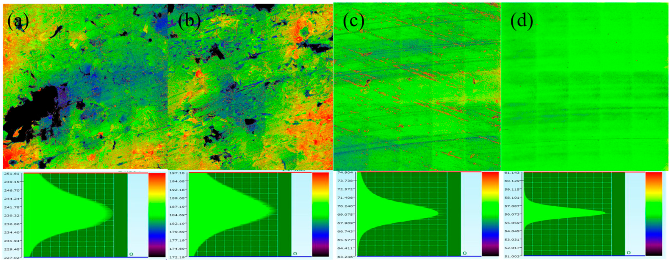
3.2. Surface Topological Analysis

Table 3 and Table 4 also show the surface roughness/mechanical hardness of the friction materials and disc (before/after test), respectively. Evidently, the surface roughness, Ra, of the N/S friction materials and their BEF value were inversely proportional to the mechanical hardness from 185 HB (FC170) to 1150 HV (SCC), as shown in Table 3. As a result, as the Ra value after testing increased from 1.5 (SCC) to 2.3 μm (FC170) after the dynamometric test, the BEF values increased from 0.5 to 2.73 mg/km/vehicle (Table 1), which was well-known in previous works [21,25]. The Ra value of the NC disc (2.1 μm) for the N/S materials was comparable to that of the GCI (FC200, 2.2 μm) and was much larger than the SCC (1.5 μm), which was well-consistent with the BEF measurement results.
However, the evolution of surface roughness (Ra) and PM emissions for the L/S materials cannot be explained solely by the influence of disc hardness, because the BEF of the NC disc was larger than that of the FC170 and SCC discs. As shown in Table 3, the Ra values of the friction materials for the FC170 and SCC discs were reduced after dynamometric tests, which indicated the formation of a smooth friction layer due to contact between the friction materials and discs.
In contrast to the cases of FC170 and SCC, the Ra value of the L/S friction materials for the NC disc increased from 1.2 to 1.8 μm after the dynamometric test, which suggested that the smooth friction layer was destroyed by severe wear. The increased Ra value of the NC disc implied that a more severe character of wear was present in the pair of NC disc and L/S materials. Such an implication was also proved by FE-SEM images of discs (Figure 3) and laser confocal microscope images of friction materials (Section 3.3). The NC disc exhibited a number of large pits, which might have been due to the aggressive attack of L/S materials, along with higher roughness values. L/S materials worn by the NC disc showed a larger area of low land in laser confocal microscope images, as shown in Figure 5a. In this work, increased pad (11 × 10−5 kg) and disc wear amount (77 × 10−5 kg) for the NC disc compared with GCI and SCC, as shown in Table 2, were also coincident with the occurrence of an aggressive attack of L/S materials toward the NC disc.
In general, the surface roughness of friction materials and discs increases when wear becomes more pronounced [26], as suggested by the lower COF value of the NC (0.48) compared with the FC170 (0.49) and SCC (0.60) in Table 2. Higher roughness values of the friction materials imply reduced contact area and vice versa [27,28,29,30], which might result in the concentration of strain on the contact plateau. The surface roughness value, Ra, of the L/S materials (1.8 μm) for the NC disc was much larger than that of SCC (1.0 μm) and GCI (FC170, 1.2 μm) after the dynamometric tests, which was well consistent with the relatively higher wear of the pair of NC disc and L/S materials.
In general, a lower COF value implies that the contact area between the friction materials and disc is less and vice versa [27,28,29,30]. Therefore, it was speculated that the NC disc had the smallest contact area, while the SCC had the largest contact area. With increasing contact area, the strain exerted on the contact area was distributed and became less for the same area. This situation resulted in a relatively reduced wear amount of the friction material and disc.
For the SCC disc, the hard friction layer was well maintained due to the large contact area, which enhanced the wear resistance and PM emission characteristics. On the other hand, the COF for the NC disc was the lowest of the three discs, and the contact area was the smallest, in which the mechanical strain was relatively concentrated on the same contact area. Even though the hardness of transfer layer for the NC was higher than that for the FC170, the higher strain was concentrated on the contact area compared with the FC170, which resulted in the occurrence of stronger wear and a subsequent higher BEF value.
Such an increase in COF with reduced wear rate was also reported in a previous pin-on-disc study on an HVOF-coated WC-CoCr disc [31,32]. It has been reported that, in Ra (disc) < 1 μm, the adhesive interaction between pin and disc strongly increased with increasing COF [31]. Increased compactness of the secondary plateau was also reported to contribute to the real area of contact, which reduced the wear rate of both contact surfaces [32]. These pin-on-disc results were well-consistent with our higher COF and reduced-wear amounts for the SCC disc (Table 1 and Table 2). This feature also clarified that the SCC disc was superior to the NC disc in PM emission and wear rate for L/S materials, not only because the SCC had higher hardness but also because the wear characteristic of the NC disc was more severe.
Figure 3. (a) BSE (backscatter electron) and (b) FE-SEM images of the NC disc with the L/S friction materials as a counterpart. Random-shaped small particles were found in large pits, with 50–100 μm in the wear track of the NC disc showing more severe wear. The particles could either be iron oxide from the GCI substrate or wear debris transferred from the friction materials. (c) BSE and (d) FE-SEM images showing lots of cracks between the iron nitride and GCI matrix, which was created by the wear process to produce wear debris [33,34]. (e) EDS mapping images and (f) FE-SEM of wear tracks showing large pits of 50–100 μm in the disc surface. EDS mapping images of (g) oxygen, (h) Fe, (i) carbon, and (j) Ca in the wear track, showing that oxide materials were present in the large pits.
Lubricants 11 00526 g003
The roughness of the worn surface of disc rotors also indicated there was a different wear mechanism for the pair of NC disc and L/S friction materials (Table 4). The NC disc exhibited a higher Ra value and underwent a smaller reduction in Ra value, from 0.42 to 0.37, compared with the FC170 and SCC (0.25 → 0.17 μm, 0.14 → 0.12 μm) in Table 4. These results indicated that a rough NC disc evidenced more severe wear, which might have been related to the coefficient of friction (COF). The COF values of the FC170, NC, and SCC discs for the L/S materials were 0.49, 0.48, and 0.60, respectively (Table 2). Relatively higher wear occurred for the pair of NC disc and L/S materials compared with pairs of the SCC/FC170 discs and the L/S materials, and therefore, it could also result in a lower COF value compared with the SCC/FC170.
For the L/S materials, disc wear was dominant in the wear process, indicating that the positive influence of the hardening of the NC disc was overwhelmed by the severity of wear between the NC and the L/S materials. The difference in the wear mechanisms of the NC and SCC discs with respect to the L/S materials was supported by (1) surface topology analysis results of the friction material/disc and (2) microstructure and chemical analyses. For (1), the surface roughness of the worn friction materials was measured, which is well-known to represent the character of wear mechanism [21,25].
In contrast to the case with the L/S materials, it appeared that the influence of the severity of wear was not dominant for the N/S materials compared with disc hardening. The BEF value of the NC (1.74 mg/km) was comparable to that of the FC200 (1.76 mg/km) in Table 1, and the COF value of the NC (0.37) was slightly lower than that of the FC170 (0.42) in Table 1. Disc wear of the NC was reduced by 67% (60 × 10−6 kg → 20 × 10−6 kg) due to the enhanced hardness of the NC disc (670 HV) compared with the FC170(185HB), as shown in Table 1. Meanwhile, the pad wear of the NC was also reduced by 50% (32 × 10−6 kg → 16 × 10−6 kg).
A comprehensive interpretation of the wear amounts and the COFs suggests that the disc hardening of the NC disc appeared to compensate the influence of the wear effect. Even though severe wear induced by the NC disc still might have been present, as shown by the slight lower COF than FC170, the aggressive attack on the disc rotors by the N/S friction materials appeared to have not been as severe as the L/S materials. As a result, the BEF value for the NC (670 HV) appeared to be comparable to that for the FC200, with higher disc hardness (210 HB) than the FC170 (185 HB).

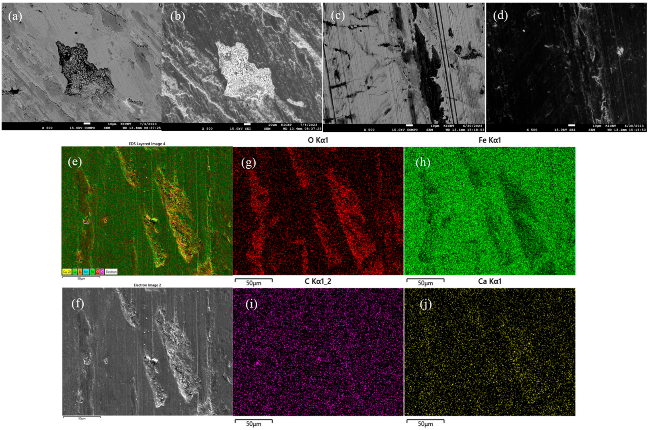
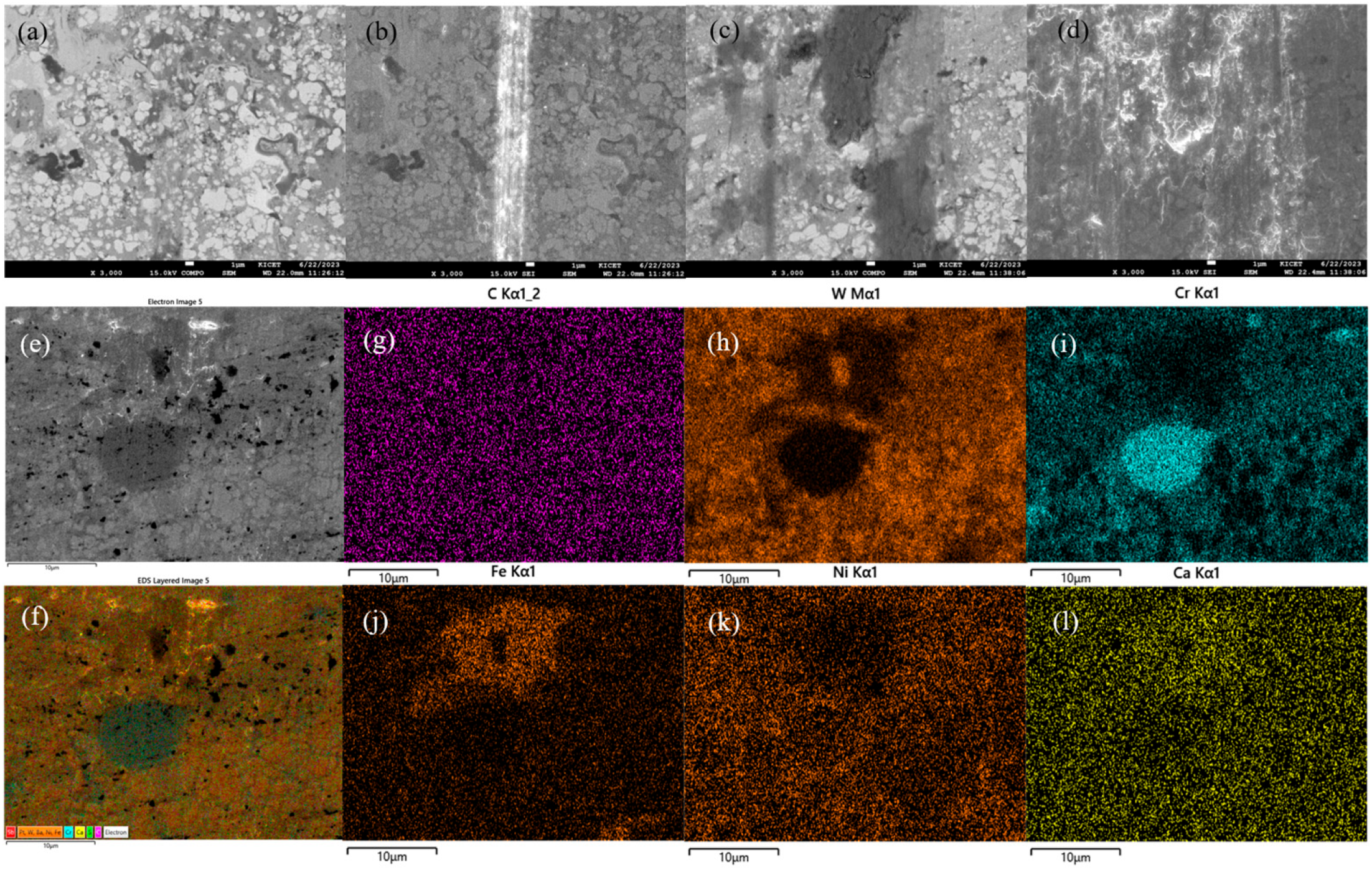
3.3. Microstructure Analysis

To clarify the difference between the wear mechanisms of the NC and SCC discs against the L/S friction materials, SEM and EDS were used to characterize the morphology and chemical composition of the worn tracks. Figure 3 shows the SEM and BSE (backscatter electron) images of the worn track from the NC sample. First, the width of the wear track was estimated to be from 30 to 50 μm. Second, there were more grooves along the sliding direction in the worn track (Figure 3c), indicating severe wear of the NC sample by the L/S materials. Third, a large number of concave pits (Figure 3a,e) were found in the center of the worn track. Further magnification, as shown in Figure 3c, indicated the surface materials had peeled off and left large concave pits on the worn tracks. The deformation of the Fe2–3N and Fe4N surface layer under the compressive and shear stresses during the wear process was shown to be abraded by the wear process, producing wear debris [33,34]. In addition, aggregates of particles were found in large pits, b 50–100 μm, as shown in Figure 3a. Large concave pits were found, in which oxygen was enriched, as shown in Figure 3e–j. The concave pits were either iron oxide from the GCI substrate or wear debris transferred from the friction materials. The above analysis indicated that the wear mechanism of the NC samples included abrasion, oxidation wear, and peeling wear.
Figure 4 shows the SEM morphologies and EDS analysis of the worn tracks for the SCC sample. First, the worn track was evidently narrower than that of the NC sample (~10 μm). Second, in Figure 4b, a bright belt was observed in BSE mode, indicating that lighter elements than W were present in the middle of the worn track. Figure 4c,d show dark areas in the wear tracks, some of them containing materials transferred from the L/S materials. The dark areas were smooth and grainy wear debris was not observed in the area, as shown in the magnified image in Figure 4c,d. The absence of large concave pits or particles on the SCC disc, unlike the NC, implied that severe wear did not occur for the SCC disc with the L/S materials, suggesting a third body wear mechanism.
The EDS analysis (Figure 4e–l) showed that the dark regions in the wear tracks contained no oxygen, Ni, Cr, or Fe, while Fe from the L/S materials had accumulated in some dark areas (Figure 4j), indicating that the belts (Figure 4b) were layers transferred from the friction materials. The Fe-rich areas were relatively light in color, like the Cr-rich regions in the SEM mode, and darker in the backscatter electron mode. Considering their morphology and chemical composition, it was assumed that some of dark regions corresponded to the second phase of Cr carbide (Figure 4i), along with some Fe-rich regions (Figure 4j), transferred from the L/S materials. The EDS analysis showed that Fe-enriched areas were found in parts of the dark regions, suggesting that the areas were formed by transfer from the friction materials during the wear process.
The severe wear induced by the NC disc, as expected from lower COF than the FC170 and SCC discs, was clearly shown in the surface profile by the laser confocal microscope in contrast with that by the SCC disc. The surface profile of the NC disc (Figure 5c) as a counterpart of L/S friction materials (Figure 5a) exhibited a large number of low land in friction materials and conspicuous wear tracks in the NC disc compared with the SCC disc (Figure 5b,d). Histograms of relative height (lower panel) also indicated that relative severe wear characteristics by the NC disc rotor were present.

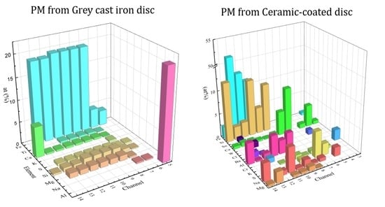
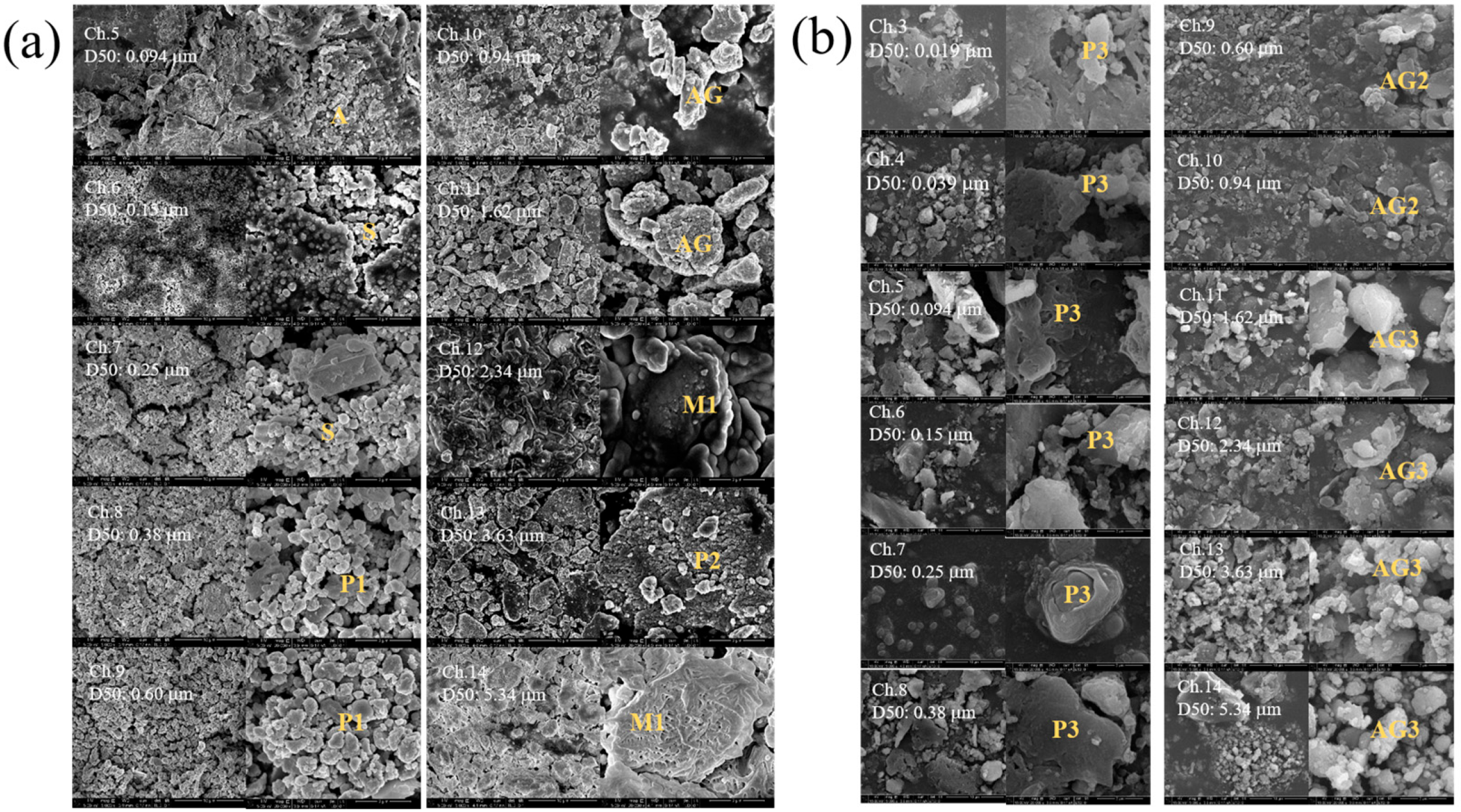
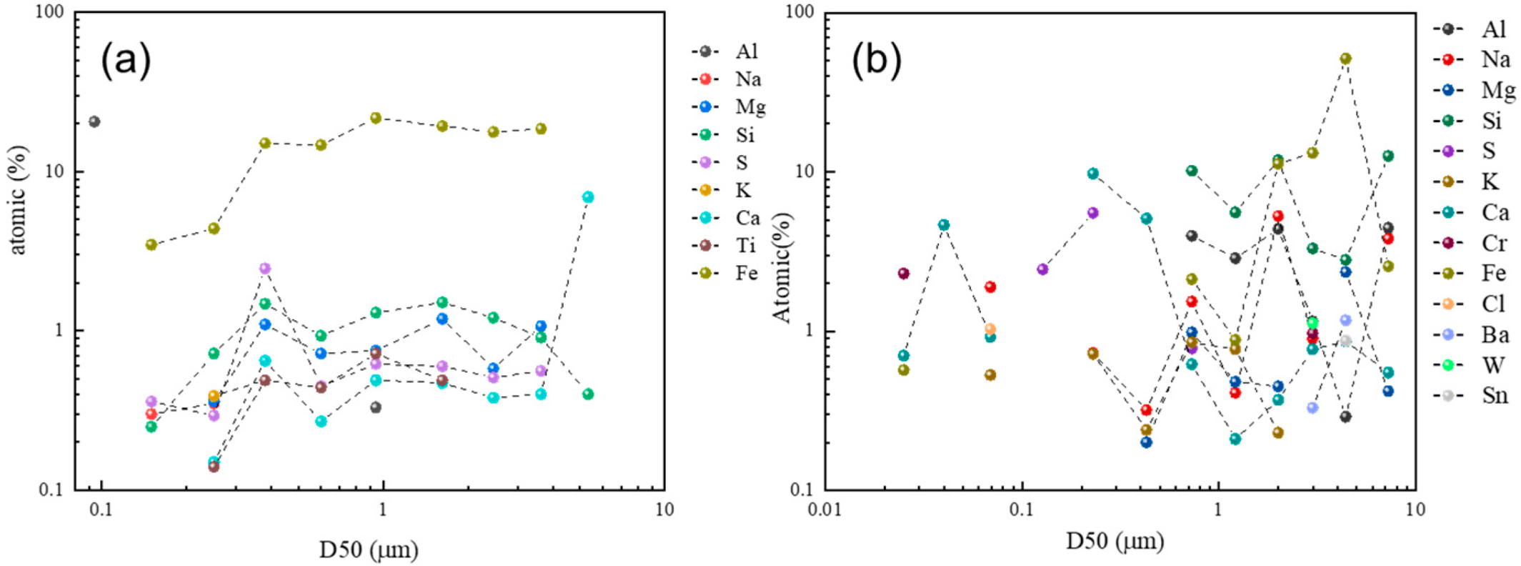
3.4. Wear Debris Analysis

In this work, wear debris was classified and collected by a cascade impactor into 14 size fractions ranging from 16 nm to 10 μm. The particles of each size fractions were collected by a cascade impactor of HR-ELPI+; however, the particles in 10 and 12 out of 14 channels for N/S and L/S materials, respectively, were able to be analyzed in amounts. The size-classified particles were collected during dynamometric tests of the pairs of L/S friction materials and the GCI/SCC discs. We investigated the composition and morphology of the airborne PM by FE-SEM/EDS analyses, which clarified the origin of the brake wear particles and the influence of the surface hardness of the disc rotor.
As shown in the FE-SEM analysis results (Figure 6a), six morphological categories of wear debris were found for the GCI disc rotor: (1) Al2O3 or Al (A), (2) sphere (S), (3) plate-type aggregate (P1), (4) aggregate (AG), (5) melt (M1), and (6) large plate-type agglomerate (P2). Based on the channels in the impactor, the majority of the wear debris had a different morphology (shape and size) and chemical elements. In channel 5 (D50: 0.094 μm), aggregates of alumina (A) from friction materials or Al from ELPI+ were found. Sphere-shaped particles were found in channels 6 and 7 (D50: 0.15, 0.25 μm), and Na, S, and Si were found in the EDS analysis, along with a majority of Fe. This suggests that the spherical particles(S) were related to the Na, S, and Si elements. In channels 8 to 13 (D50: 0.38–3.63 μm), plate-type aggregate (P1), aggregate (AG), melt (M1), and large plate-type agglomerate (P2) were found, and their constituents contained Fe, Si, Mg, S, Ti, and Ca elements according to the EDS analysis. The plate-type aggregate (P1) was loosely bound small primary particles, whereas the large plate type agglomerate (P2) was a more densely bound agglomerate of primary particles, with a size of more than 2 μm. In channel 14 (D50: 5.34 μm), only Ca and Si elements were detected, as well as large melt-like particles (M1) that looked like fused melt-like particles with round edges. The M1 could be directly sheared off from the contact surfaces.
According to the EDS analysis results (Figure 7), Fe was the major element, which came from the GCI disc rotor and, in part, L/S friction materials. Micron-sized particles, which mainly originated from fragmented Fe lumps from the GCI, were observed at D50 = 0.1–3.5 μm. Mg, Si, S, Ca, and Ti were minor components, originating from the friction materials. In Figure 6a, P1 and P2-type particles were probably large Fe lumps or plates separated from GCI by fragmentation without considerable chemical oxidation. AG-type particles seemed to be an aggregation/agglomeration of submicron-sized particles, formed by evaporation–condensation processes around the cores (e.g., small Fe lumps) [35].
For the SCC disc rotor, as shown in Figure 6b, airborne PM with simpler morphology was found. In channels 3–8 (D50: 0.019–0.38 μm), plate-shaped particles or their agglomerates (P3) were found, and their chemical elements were various (with a majority of Ca), which originated from the L/S materials. Alkaline (Na, K), sulfur, and chlorine elements were also found, which originated from the L/S materials. The concentration of Fe from the SCC disc was greatly reduced in comparison with the GCI disc, which indicated that the SCC disc had relatively lower disc wear. This was probably due to the absence of fragmented Fe particles from the GCI disc and their aggregates.
In channel 3 (D50: 0.019 μm), chromium was found, which might have come from the SCC disc, since no chromium was detected for the GCI disc. In channels 9–14, micron-sized aggregates were found and, according to EDS analysis, the major elements were Fe, Si, and Al, which would have originated from the L/S materials. Since significant wear of the SCC disc did not occur during the dynamometric tests, the Fe-based substrate was not exposed to an aggressive attack by the friction material. Then, the majority of the detected Fe element might have originated from the L/S friction materials, with the minority from the disc rotor. An aggregate in the channel with larger D50 diameters (D50 > 0.6 μm) also contained large amounts of Si and Al, which would have originated from constituents in the L/S friction materials.
Therefore, aggregates containing steel fiber and abrasives (D50 = 1.0–3.5 μm) might have been created during the wear process and transferred from the L/S friction materials. This result implies that materials transferred from L/S materials are a major source of airborne PM from brake wear for the SCC rotor with higher surface hardness.
Figure 6. FE-SEM images of collected airborne PM in the size-classified ELPI channels for the (a) GCI(FC170) and (b) SCC discs.
Lubricants 11 00526 g006
Figure 7. Results of the chemical analysis of airborne PM for (a) the FC170 disc and (b) the SCC disc according to D50 size of the ELPI channel.
Lubricants 11 00526 g007

4. Conclusions

In this work, we investigated airborne PM emissions from an automobile disc brake system according to the surface materials of the disc rotors under brake dynamometer operation. Three types of disc materials—gray cast iron (GCI), nitrocarburized GCI (NC), and superhard ceramic-coated GCI (SCC)—were examined in relation to surface topography and microstructural analysis.
  • Dynamometric PM measurements based on the NOVEL cycle showed that the brake emission factor (BEF) for the SCC rotor was reduced by more than a factor of 1/5 compared with the GCI and NC, while the coefficient of friction (COF) of the SCC increased by >20% compared with the GCI and NC rotors.
  • With increasing disc hardness in the order of FC170 → FC200 → NC → SCC, the BEF for the N/S materials was decreased from 2.73 to 0.5 mg/km/vehicle. On the other hand, the BEF value of the NC disc rotor (6.26 mg/km/vehicle) was higher than the GCI (4.85 mg/km/vehicle) and SCC rotors (0.64 mg/km/vehicle) because of more severe character of wear mechanism.
  • According to surface profile analyses of the disc rotors and friction materials worn by dynamometric tests, severe wear was conspicuous for the NC rotor, especially with the L/S friction materials, in contrast to the SCC rotor. Microstructural analysis confirmed that severe wear, involving wear debris from cracks in the nitride layer, was present for the NC disc rotor with L/S materials.
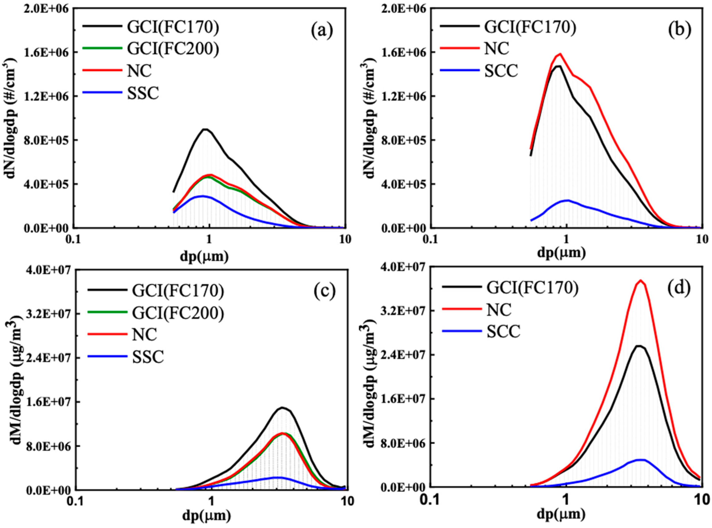
  • Results of FE-SEM and EDS analyses of the size-classified airborne PM indicated that micron-sized particles, which mainly originated from fragmented Fe lumps from the GCI disc rotor, were observed at D50 = 0.1–3.5 μm. Aggregates of steel fiber and friction materials were observed for the SCC rotor at D50 = 1.0–3.5 μm without Fe lumps from the disc rotor, which was responsible for the lower BEF due to the enhanced surface hardness of the SCC rotor.

Supplementary Materials

The following are available online at https://www.mdpi.com/article/10.3390/lubricants11120526/s1: Test procedure, Figure S1: Time-resolved vehicle speed for the NOVEL brake cycle, Table S1: Time table of NOVEL brake cycle, PM measurement, friction materials, Table S2: Formulation of non-steel and low-steel friction materials, Figure S2: Surface coating of disc rotors, Figure S3: EDS analysis result of collected PM, Figure S4: Particle size distribution (PSD) curves of airborne PM emissions, measured by ELPI+ device, for L/S friction materials based on (a) particle number and (c) particle mass. Figure S5: High-resolution images of Figure 3 and Figure 4.

Author Contributions

Conceptualization, J.-Y.K. and M.H.J.; methodology, Y.-S.O.; formal analysis, M.H.J. and S.H.H.; resources, W.C.S.; data curation, M.H.J.; writing—original draft preparation, J.-Y.K.; writing—review and editing, H.S. and H.J.; supervision, H.J.; project administration, J.L.; funding acquisition, J.-H.P. All authors have read and agreed to the published version of the manuscript.

Funding

This work was financially supported under the program “Development of the high-performance brake for passenger car and commercial vehicle to reduce particulate matter” (20003598) and “Ceramic Strategy Technology Development” by Ministry of Trade, Industry, and Energy of Korea.

Data Availability Statement

Data are contained within the article.

Conflicts of Interest

Authors of Won Cheol Shin and Jung-Ju Lee are employed by the companies of Myunghwa industry and Sangsin brake, respectively. The remaining authors declare that the research was conducted in the absence of any commercial or financial relationships that could be construed as a potential conflict of interest.

References

  1. Rashid, A. Overview of disc brakes and related phenomena—A review. Int. J. Veh. Noise Vib. 2014, 10, 257–301. [Google Scholar] [CrossRef]
  2. Cueva, G.; Sinatora, A.; Guesser, W.L.; Tschiptschin, A.P. Wear resistance of cast irons used in brake disc rotors. Wear 2003, 255, 1256–1260. [Google Scholar] [CrossRef]
  3. Thornton, R.; Slatter, T.; Jones, A.H.; Lewis, R. The effects of cryogenic processing on the wear resistance of grey cast iron brake discs. Wear 2011, 271, 2386–2395. [Google Scholar] [CrossRef]
  4. Vasiljević, S.; Glišović, J.; Stojanović, B.; Vencl, A. Review of the coatings used for brake discs regarding their wear resistance and environmental effect. Proc. Inst. Mech. Eng. Part J J. Eng. Trib. 2022, 236, 1932–1949. [Google Scholar] [CrossRef]
  5. Garg, B.D.; Cadle, S.H.; Mulawa, P.A.; Groblicki, P.J.; Laroo, C.; Parr, G.A. Brake Wear Particulate Matter Emissions. Environ. Sci. Technol. 2000, 34, 4463–4469. [Google Scholar] [CrossRef]
  6. Kumar, P.; Pirjola, L.; Ketzel, M.; Harrison, R.M. Nanoparticle emissions from 11 non-vehicle exhaust sources—A review. Atmos. Environ. 2013, 67, 252–277. [Google Scholar] [CrossRef]
  7. Hagino, H.; Oyama, M.; Sasaki, S. Laboratory testing of airborne brake wear particle emissions using a dynamometer system under urban city driving cycles. Atmos. Environ. 2016, 131, 269–278. [Google Scholar] [CrossRef]
  8. Iijima, A.; Sato, K.; Yano, K.; Kato, M.; Tago, H.; Kato, M.; Kimura, H.; Furuta, N. Particle size and composition distribution analysis of automotive brake abrasion dusts for the evaluation of antimony sources of airborne particulate matter. Atmos. Environ. 2007, 41, 4908–4919. [Google Scholar] [CrossRef]
  9. Herman, H.; Sampath, S. Thermal spray coatings. In Metallurgical and Ceramic Protective Coatings; Springer: Dordrecht, The Netherlands, 1996; pp. 261–289. [Google Scholar]
  10. Mandich, N.V.; Snyder, D.L. Electrodeposition of chromium. In Modern Electroplating; Schlesinger, M., Paunovic, M., Eds.; Wiley: Hoboken, NJ, USA, 2010; pp. 205–241. [Google Scholar]
  11. Dunleavy, C.S.; Golosnoy, I.O.; Curran, J.A.; Clyne, T.W. Characterisation of discharge events during plasma electrolytic oxidation. Surf. Coat Technol. 2009, 203, 3410–3419. [Google Scholar] [CrossRef]
  12. Van Acker, K.; Vanhoyweghen, D.; Persoons, R.; Vangrunderbeek, J. Influence of tungsten carbide particle size and distribution on the wear resistance of laser clad WC/Ni coatings. Wear 2005, 258, 194–202. [Google Scholar] [CrossRef]
  13. Fernandes, F.; Cavaleiro, A.; Loureiro, A. Oxidation behavior of Ni-based coatings deposited by PTA on gray cast iron. Surf. Coat. Technol. 2012, 207, 196–203. [Google Scholar] [CrossRef]
  14. Cho, Y.W.; Won, J.H.; Woo, J.H.; Yu, S.H.; Cho, Y.R. Effect of oxy-nitrocarburizing on microstructure, nanohardness and corrosion properties for low carbon steel. Kor. J. Met. Mater. 2018, 56, 289–295. [Google Scholar]
  15. Sanders, P.G.; Xu, N.; Dalka, T.M.; Maricq, M.M. Airborne brake wear debris: Size distributions, composition, and a comparison of dynamometer and vehicle tests. Environ. Sci. Technol. 2003, 37, 4060–4069. [Google Scholar] [CrossRef]
  16. Wahlstrom, J.; Olander, L.; Olofsson, U. Size, shape, and elemental composition of airborne wear particles from disc brake materials. Tribol. Lett. 2010, 38, 15–24. [Google Scholar] [CrossRef]
  17. Grigoratos, T.; Martini, G. Brake wear particle emissions: A review. Environ. Sci. Pollut. Res. Int. 2015, 22, 2491–2504. [Google Scholar] [CrossRef] [PubMed]
  18. Perricone, G.; Alemani, M.; Metinöz, I.; Matějka, V.; Wahlström, J.; Olofsson, U. Towards the ranking of airborne particle emissions from car brakes–a system approach. Proc. Inst. Mech. Eng. Part D J. Automob. Eng. 2017, 231, 781–797. [Google Scholar] [CrossRef]
  19. Perricone, G.; Matějka, V.; Alemani, M.; Valota, G.; Bonfanti, A.; Ciotti, A.; Olofsson, U.; Söderberg, A.; Wahlström, J.; Nosko, O.; et al. A concept for reducing PM10 emissions for car brakes by 50%. Wear 2018, 396, 135–145. [Google Scholar] [CrossRef]
  20. Krenkel, W.; Heidenreich, B.; Renz, R. C/C-SiC composites for advanced friction systems. Adv. Eng. Mater. 2002, 4, 427–436. [Google Scholar] [CrossRef]
  21. Kim, S.H.; Shim, W.; Kwon, S.U.; Lee, J.J.; Seo, M.; Kim, J.; Pee, J.; Kim, J. The impact of composition of non-steel and low-steel type friction materials on airborne brake wear particulate emission. Tribol. Lett. 2020, 68, 118. [Google Scholar] [CrossRef]
  22. Mathissen, M.; Grochowicz, J.; Schmidt, C.; Vogt, R.; Farwick zum Hagen, F.H.; Grabiec, T.; Steven, H.; Grigoratos, T.A. Novel real-world braking cycle for studying brake wear particle emissions. Wear 2018, 414–415, 219–226. [Google Scholar] [CrossRef]
  23. Seo, H.; Park, J.; Kim, Y.C.; Lee, J.J.; Jang, H. Effect of disc materials on brake emission during moderate-temperature braking. Tribol. Int. 2021, 163, 107185. [Google Scholar]
  24. Shen, M.; Li, H.; Du, J.; Ji, D.; Liu, S.; Xiao, Y. New insights into reducing airborne particle emissions from brake materials: Grooved textures on brake disc surface. Tribol. Int. 2022, 174, 107721. [Google Scholar] [CrossRef]
  25. Seo, H.; Lee, D.G.; Park, J.; Song, W.; Lee, J.J.; Sohn, S.S.; Jang, H. Quench hardening effect of gray iron brake discs on particulate matter emission. Wear 2023, 523, 204781. [Google Scholar] [CrossRef]
  26. Popov, V.L. Contact Mechanics and Friction; Springer: Berlin/Heidelberg, Germany, 2010; Chapter 3. [Google Scholar]
  27. Al-Samarai, R.A.; Haftirman; Ahmad, K.R.; Al-Douri, Y. The influence of roughness on the wear and friction coefficient under dry and lubricated sliding. Int. J. Sci. Eng. Res. 2012, 3, 1–6. [Google Scholar]
  28. Wang, A.; Plineni, V.K.; Stark, C.; Dumbleton, J.H. Effect of femoral head surface roughness on the wear of ulrahigh molecular weight polyethylene acetabular cups. J. Arthroplast. 1998, 13, 615–620. [Google Scholar] [CrossRef] [PubMed]
  29. Jiang, J.; Arnell, R.D. The effect of substrate surface roughness on the wear of DLC coatings. Wear 2000, 239, 1–9. [Google Scholar] [CrossRef]
  30. Park, J.; Joo, B.; Seo, H.; Song, W.; Lee, J.J.; Lee, W.K.; Jang, H. Analysis of wear induced particle emissions from brake pads during the worldwide harmonized light vehicles test procedure (WLTP). Wear 2021, 466–467, 203539. [Google Scholar] [CrossRef]
  31. Federici, M.; Menapace, C.; Moscatelli, A.; Gialanella, S.; Straffelini, G. Effect of roughness on the wear behavior of HVOF coatings dry sliding against a friction material. Wear 2016, 368–369, 326–334. [Google Scholar] [CrossRef]
  32. Wahlstrom, J.; Lyu, Y.; Matjeka, V.; Soderberg, A. A pin-on-disc tribometer study on disc brake contact pairs with respect to wear and airborne particle emissions. Wear 2017, 384–385, 124–130. [Google Scholar] [CrossRef]
  33. Shinde, T.; Dhokey, N.B. Influence of carbide density on surface roughness and quasi-stable wear behaviour of H13 die steel. Surf. Eng. 2017, 33, 944–952. [Google Scholar] [CrossRef]
  34. Shinde, T. Influence of carbide particle size on the wear performance of cryogenically treated H13 die steel. Surf. Eng. 2020, 37, 1206–1214. [Google Scholar] [CrossRef]
  35. Kim, S.H.; Jeong, M.H.; Kim, J.; Shim, W.; Kwon, S.U.; Lee, J.J.; Huh, S.H.; Pee, J.H.; Kim, J.Y. Dynamometric Investigation on Airborne Particulate Matter (PM) from Friction Materials for Automobile: Impact of Abrasive and Lubricant on PM Emission Factor. Lubricants 2021, 9, 118. [Google Scholar] [CrossRef]
Figure 1. (a) A schematic of the brake dynamometer and PM measurement devices. The brake assembly was situated in constant environmental conditions (temperature and humidity) controlled by an environment control unit (ECU). Incoming air was passed through HEPA filters to prevent experimental errors from outside PM. Isokinetic sampling of particles was conducted from the center of the long straight transport line. CVS: constant volume sampling system; OPC: optical particle counter; ELPI: electrical low-pressure impactor. (b) Image of the dynamometer and particle measurement system.
Lubricants 11 00526 g001
Figure 2. Particle size distribution (PSD) curves of airborne particulate matter (PM) emissions for N/S friction materials based on (a) particle number and (c) particle mass. For L/S friction materials, the PSD curves of airborne PM emission based on (b) particle number and (d) particle mass are presented. Curves for particle mass were calculated from the particle number using channel diameter and density.
Lubricants 11 00526 g002
Figure 4. (a) BSE (backscatter electron) and (b) FE-SEM images of the SCC disc using the L/S friction materials as a counterpart. Bright belts (indicating that lighter elements than W were present) were found in the middle of the wear tracks in the BSE mode. (c) BSE and (d) FE-SEM images showing dark areas of ~10 μm, probably containing iron transferred from friction materials, were also found in the wear tracks. Unlike the NC disc, large concave pits were not found, which implies the severe wear did not occur for the SCC disc and L/S materials pair. (e) EDS mapping images and (f) FE-SEM of wear tracks showing dark areas of 10 μm on the disc surface. EDS mapping images of (g) carbon, (h) W, (i) Cr, (j) Fe, (k) Ni, and (l) Ca showing the dark regions corresponding to either a second phase of chromium carbide, formed during the HVOF coating, or a Fe-enriched phase transferred from the L/S friction materials. Elements (in wt%) found were Al (0.31), S (0.69), Ca (0.36), Cr (22.32), Fe (4.80), Ni (9.86), Sb (0.58), Ba (0.69), and W (60.39).
Lubricants 11 00526 g004
Figure 5. Surface profiles of the L/S friction materials for (a) the NC and (b) the SCC disc rotors using laser confocal microscope. Surface profiles of (c) the NC and (d) the SCC rotors for the L/S materials by laser confocal microscope are shown. Color maps of the worn surface are shown in relation to the color scale below: Red (high) → Black (low). Histograms of the relative height are also shown below.
Lubricants 11 00526 g005
Table 1. Dynamometric test results of the gray cast iron (FC200, FC170), nitrocarburized (NC), and superhard ceramic-coated (SCC) discs for non-steel (N/S) friction materials. Brake emission factor (BEF), pad wear, and disc wear decreased as the hardness of the disc surface material increased (FC170 → FC200 → NC → SCC).
N/S Friction MaterialsGCI Disc (FC170)GCI Disc (FC200)NC DiscSCC Disc
BEF (mg/km/vehicle) 12.731.761.740.50
Pad wear (kg)32(3) × 10−616(2) × 10−616(2) × 10−68(1) × 10−6
Disc wear (kg)60(6) × 10−610(1) × 10−620(2) × 10−610(1) × 10−6
Avg. COF 20.42(2)0.40(2)0.37(2)0.47(2)
Hardness185 HB210 HB670 HV1150 HV
1 BEF—conventional brake emission factor (mg/km/vehicle); 2 COF (coefficient of friction) values were obtained by a tribology test according to SAE J2522.
Table 2. Dynamometric test results of gray cast iron (GCI and FC170), nitrocarburized (NC), and superhard ceramic-coated (SCC) discs for low-steel (L/S) friction materials. Brake emission factor (BEF), pad wear, and disc wear of the SCC disc rotor were greatly reduced compared with the GCI and NC discs. The NC disc exhibited the highest BEF value, pad wear, and disc wear among discs due to the more severe character of the wear mechanism, as shown by the lowest COF value.
L/S Friction MaterialsGCI Disc (FC170)NC DiscSCC Disc
BEF (mg/km/vehicle) 14.856.260.64
Pad wear (kg)89(8) × 10−611(1) × 10−573(7) × 10−6
Disc wear (kg)67(7) × 10−577(5) × 10−529(3) × 10−5
Hardness185 HB670 HV1150 HV
Avg. COF 20.49(2)0.48(2)0.60(3)
1 BEF—conventional brake emission factor (mg/km/vehicle); 2 COF (coefficient of friction) values were obtained by a tribology test according to SAE J2522.
Table 3. Surface topography analysis results of the L/S and N/S friction materials before/after tests. Roughness (Ra) values of the friction materials decreased after tests as the disc hardness increased.
N/S Friction MaterialsL/S Friction Materials
Counterpart discGCI disc (FC170)GCI disc (FC200)NC discSSC discGCI disc (FC170)NC discSCC disc
Ra (μm), before test1.8 (3)1.2 (2)
Ra (μm), after test2.3 (5)2.2 (5)2.1 (3)1.5 (2)1.2 (4)1.8 (5)1.0 (2)
Table 4. Surface topological analysis results of disc rotors before/after tests. The roughness (Ra) values of the disc materials after tests decreased as the hardness of disc materials increased.
GCI Disc (FC170)GCI Disc (FC200)NC DiscSCC DiscGCI Disc (FC170)NC DiscSCC Disc
Counterpart Disc (Friction Materials)N/S Friction MaterialsL/S Friction Materials
Ra (μm), before test2.19 (6)2.30 (5)0.9 (2)0.12 (1)2.30 (6)0.88 (6)0.12 (1)
Ra (μm), after burnish0.25 (7)0.26 (6)0.17 (7)0.13 (1)0.25 (6)0.42 (5)0.14 (1)
Ra (μm), after test0.23 (6)0.23 (6)0.19 (6)0.12 (2)0.17 (6)0.37 (5)0.12 (2)
Hardness210 HB185 HB670 HV1150 HV185 HB670 HV1150 HV
Disclaimer/Publisher’s Note: The statements, opinions and data contained in all publications are solely those of the individual author(s) and contributor(s) and not of MDPI and/or the editor(s). MDPI and/or the editor(s) disclaim responsibility for any injury to people or property resulting from any ideas, methods, instructions or products referred to in the content.

