How Do Substrates Affect the Friction on Graphene at the Nanoscale?
by
Haochen Feng
1, 
Ziwen Cheng
1,*,
Dongxu Long
2,
Tingting Yang
1,
Zhibin Lu
3 and
Qichang He
1,4,* 1
School of MechaNichal Engineering, Southwest Jiaotong University, Chengdu 610031, China
2
Sanechips Technology Co., Ltd., Shenzhen 518055, China
3
State Key Laboratory of Solid Lubrication, Lanzhou Institute of Chemical Physics, Chinese Academy of Sciences, Lanzhou 730000, China
4
Modélisation et Simulation Multi Échelle (MSME), Centre National de la Recherche Scientifique (CNRS), Unite Mixte de Recherche (UMR), Université Gustave Eiffel, F-77454 Marne-la-Vallée, France
*
Authors to whom correspondence should be addressed.
Lubricants 2023, 11(11), 465; https://doi.org/10.3390/lubricants11110465
Submission received: 12 September 2023
/
Revised: 4 October 2023
/
Accepted: 28 October 2023
/
Published: 30 October 2023
(This article belongs to the Special Issue Friction and Wear on the Atomic Scale)
Abstract
:Substrates supporting two-dimensional materials are omnipresent in micro/nano electromechanical systems. Moreover, substrates are indispensable to all nanotribological experimental systems. However, substrates have rarely been taken into account in first-principles simulations of nanotribological systems. In this work, we investigate the effects of substrates on nanofriction by carrying out first-principles simulations of two systems: (a) one graphene monolayer sliding on another one supported by a metal substrate, denoted as the Gr-Gr/Metal system; and (b) a diatomic tip sliding on a graphene monolayer supported by a metal substrate, named the Tip-Gr/Metal system. Each substrate is made of triatomic layers constituting the minimum period and obtained by cutting a metal through its (111) surface. By varying metal substrates and analyzing the results of the first-principles simulations, it follows that (i) the fluctuation in the sliding energy barriers of the two systems can be modified by changing substrates; (ii) the adsorption type and the pressure affect friction; (iii) the presence of a substrate varies the interfacial binding strength; and (iv) the modulation of friction by substrates lies in altering the interface electron density. These results provide an answer to the important question of how substrates affect the friction on graphene at the nanoscale.

1. Introduction
Micro/nano electromechanical systems (MEMS/NEMS) are indispensable to large-scale integrated circuits and to artificial intelligence (AI) [1]. In these systems, friction, which is due to interactions at interfaces and takes place often at the nanoscale, plays an important role [2]. In particular, the reliability and lifetime of MEMS/NEMS are severely affected by the failure caused by friction. To solve this problem, two-dimensional (2D) materials have potential applications for solid lubrication in these systems [3,4], owing to their atomic-level thinness and weak interlayer interactions
When 2D materials, such as graphene [5,6,7], MoS2 [8] and h-BN [9,10], are used in experimental investigations or in practice, substrates supporting them are essential. The presence of substrates has an impact on interfacial bonding [11], fold effects [12], contact quality [13], etc. For example, Jiang et al. [14] reported that substrates can significantly alter the mechanical properties of graphene, perturb the phonon spectrum and thus alter the thermal expansion coefficient or the Young’s modulus of graphene. Moreover, the doping, degradation [15], electronic properties [11] and oxidation of graphene [16] are also constrained by the substrate.
Like the aforementioned interfacial properties, friction is also influenced by substrates. Due to the high specific surface area at low dimensions, the impacts of friction at interfaces are particularly noticeable in MEMS/NEMS assembled from 2D structures. In fact, it has been reported that substrates do affect friction [17,18,19,20]. Munther et al. [17] observed significant variations in graphene friction on different substrates, which they attributed to increased phonon scattering. Qi et al. [18] pointed out that the edge friction depends on the passivation state of the dangling bonds and the local pinning effect of the substrates from the graphene free edges. Due to fact that substrates can alter electronic properties and structure, how to modulate friction through substrates is an important question to be answered. Zeng et al. [19] suggested reducing friction on graphene by reinforcing the binding between the graphene and substrate. Shi et al. [20] suppressed folds by increasing the binding between the MoS2 and the substrate so as to realize ultra-low friction. However, in contrast to these experimental works, first-principles simulations of friction at nanoscale have rarely accounted for the influences of substrates. Moreover, the mechanisms underlying the influences of substrates on the friction at nanoscale are still unclear. Therefore, it is necessary to study the effects of different substrates on friction at the nanoscale and clarify the corresponding mechanisms [21].
The present work is dedicated to investigating the effects of substrates on the friction between two graphene layers or between a metal tip and a graphene layer. Precisely, the first-principles computations are performed to simulate (a) a Gr-Gr/Metal system made of a graphene monolayer sliding on another one supported by a metal substrate; and (b) a Tip-Gr/Metal system composed of a diatomic tip sliding on a graphene monolayer supported by a metal substrate. Different metal materials forming substrates are considered in our simulations. A substrate comprises three layers that form the minimum period. The effects of substrates on the potential energy surfaces (PES), the sliding energy barriers, and the interfacial binding are studied in detail. The question of modulating friction by changing substrates is also investigated. In particular, the key to this modulation consists in modifying the interfacial electron density.
2. Methods
To determine the effect of substrates on the friction between graphene surfaces, we first consider one graphene monolayer sliding on another one supported by a metal substrate (see Figure 1a). This face-contact pattern is abbreviated as Gr-Gr/Metal. Next, we are interested in a diatomic tip sliding on a graphene monolayer with a metal substrate as its support (see Figure 1b). This point-contact pattern is referred to as Tip-Gr/Metal. Due to computational cost, the graphene monolayer is assumed to be flat in our first-principles simulations. Note that the flatness assumption was also adopted in some models used to interpret the results of experiments revealing the mechanisms of friction [20,22,23]. Moreover, the sliding probe is simplified into a diatomic tip. This ideal probe model has been used to effectively explain some experimental phenomena [24,25,26]. As will be seen, these simplifications can significantly reduce the cost of first-principles calculations without compromising the accuracy of our simulations.
All the results to be discussed were obtained through first-principles calculations performed using CASTEP code [27,28]. To optimize and determine the electronic structures of Gr-Gr/Metal and Tip-Gr/Metal, we chose the Local Density Approximation (LDA) since it can give a better description of systems comprising graphene layers and metal substrates [11,29,30]. When Al, Pd, Ag or Pt is used as a substrate, the Brillouin zone integration is set as ; if Ni or Cu is employed a substrate, the Brillouin zone integration corresponds to . The energy cutoff was set as 450 eV for these models. A vacuum layer of at least 20 Å was introduced to mitigate the influence of the periodic lattice potential in the direction perpendicular to the sliding interface. Further details on electron the distribution calculations can be found in Appendix D.
3. Results and Discussions
To simulate the sliding process, we first vary the metal material forming a triatomic-layer substrate and then move the upper graphene layer or the diatomic probe to detect the change in friction, the bottom graphene surface and substrates being fixed. In the following calculations, for comparison, we consider free-standing graphene without any support or graphene supported by different metal substrates.
3.1. The Effect of Substrates on the Nanofriction of the Graphene Surface
First, to simulate the friction behavior of Gr-Gr/Metal or Tip-Gr/Metal, use is made of Aluminum (Al), Palladium (Pd), Copper (Cu), Platinum (Pt), Silver (Ag) and Nickel (Ni) as substrates. The crystal faces (111) of these metals are used in our simulation. Note that the metals in question are all common substrate materials in MEMS/NEMS involving graphene [31]. As a comparison, the absence of substrate is also studied. A schematic diagram of the sliding path in the cases of Gr-Gr/Metal or Tip-Gr/Metal is shown in Figure A1 (in Appendix B). The graphene surface is highly symmetric and periodic and so is its sliding behavior.
In Figure A2 (in Appendix C), we show the PES for all substrate combinations in the case of Gr-Gr/Metal (see Appendix C for more details). For a sliding at atomic scale, PES can directly indicate changes in friction from its perspective, and the frictional properties are directly reflected by the variation in the energy barrier during a movement. The interaction between graphene and the Ni substrate involves two distinct mechanisms of adsorption, referred to as Niph (physical adsorption) and Nich (chemical adsorption). It follows from Figure A2 (in Appendix C) that only the PES of the system with the Nich substrate is significantly different from that of the system without the Nich substrate, with the shift from red to yellow at the highest values indicating a decline in the peak energy barrier. In the cases of the system with any other substrate, the PES does not change much in the presence or absence of a substrate. Thus, it is concluded that the presence of the Nich substrate is favorable to the friction-reduction ability of the graphene surface. Significant changes in the PES of the Nich substrate also appear in the Tip-Gr/Metal system (see Figure A3 in Appendix C). It is noteworthy that the existence of the Pd substrate increased the friction compared with the case with no substrate. This means that the presence of a substrate does not always reduce friction in Tip-Gr/Metal. Interestingly, the PES contrast in the Gr/Gr-Metal system is significantly different from that in the Tip-Gr/Metal system, suggesting that the substrate in the point-contact model influences the friction on the graphene surface more significantly.
In order to investigate the influence of different substrates on the frictional behavior of graphene, we examined variations in the energy barriers by altering the substrate materials. These variations are presented in two distinct scenarios: (i) energy fluctuations during sliding (refer to Figure 2a,c); and (ii) the maximum energy difference during the sliding process (refer to Figure 2b,d). Energy fluctuations were calculated along the specified sliding trajectory (see Figure A1 in Appendix B), providing an effective way of illustrating changes in friction throughout the entire process. The energy fluctuations are obtained by subtracting the energy at different sliding positions from the lowest energy on the whole path. The maximum value of the energy difference , obtained by subtracting the minimum value from the maximum value of the energy during the sliding process, can measure the maximal friction. In the calculation results shown in Figure 2, Figure 3, Figure 4 and Figure 5, the materials forming substrates are specified and, in particular, the notation BLG or Gr indicates the absence of a substrate.
As for Gr-Gr/Metal systems, the fluctuations in sliding energy barriers exhibit variability across various substrates (see Figure 2a). However, the overall trend of the effects of various substrates on the energy barriers remains consistent, i.e., the introduction of a substrate can reduce the energy barrier of one graphene layer sliding on another graphene layer (see Figure 2b). It is important to note that the influence of the substrate on the energy barrier is extremely limited, apart from the Nich substrate which has superior friction-reduction capabilities (reducing it by ~0.784 meV/Å2).
Paolicelli et al. [32] used friction force microscopy (FFM) to experimentally measure the friction force of a silicon tip sliding on a graphene layer supported by a Ni substrate or a SiO2 substrate. They found that the friction force with a Ni substrate is lower than that with a SiO2 substrate. In another work [33], the authors found that enhancing the roughness of graphene through interface grain boundaries with nickel can reduce friction. It is also interesting to mention that composite coatings composed of graphene and nickel were experimentally shown to be performant in reducing friction [34,35,36].
Concerning Tip-Gr/Metal systems, the influences of various substrates on the energy barriers of a diatomic probe sliding on graphene surface fluctuate in a range around ~3.96 meV/atom (see Figure 2c). Moreover, the introduction of substrate does not always reduce friction (see Figure 2d). All substrates used reduce friction, except for the Pd substrate. Compared with the energy barriers of the Gr–Gr interface, those of the Tip–Gr interface is more sensitive to the presence of substrates. In short, the substrates affect the graphene friction in both systems.
When only physical adsorption is present, the friction on the graphene surface varies with the system in question. In the Gr-Gr/Metal system, the substrate has less effect on the interface. In the Tip-Gr/Metal system, the effect of the substrate on the friction on the graphene surface is larger, especially with the Pd or Pt substrate (see Figure 2d).
From Figure 2, it is observed that graphene supported by the Nich substrate exhibits the most remarkable friction-reduction properties among the substrates investigated. Graphene can be chemically or physically adsorbed on the Ni substrate (see Figure 3a). Niph, involves relatively weak intermolecular forces and leads to a reversible and non-permanent binding between the graphene and the Ni substrate. In contrast, Nich is characterized by stronger covalent bonds that form between graphene and the Ni atoms on the substrate surface. We calculated the sliding energy barrier of graphene under two adsorptions. It is clear from Figure 3b that the friction of Niph is significantly higher than that of Nich. A similar phenomenon occurs also in the Tip-Gr/Metal system (see Figure A4 in Appendix C). This observation underscores the pivotal role of chemical adsorption in conferring the superior friction-reduction characteristics to both Gr-Gr/Ni and Tip-Gr/Ni systems. The variation in adsorption type exerts a discernible influence on the frictional behavior of the graphene surface, even when supported by the same substrate. In contrast, the interaction between graphene and the remaining substrates is predominantly governed by physical adsorption.
In addition to the substrate material, we also considered the effect of loading on the graphene surface in the Tip-Gr/Metal systems. As the diatomic probe approaches the graphene surface from the balance position, repulsive forces arise between them, resulting in compressive stress (the calculation method for compressive stress is detailed in Appendix D). Since the friction force is calculated by dividing the sliding energy difference by the sliding distance [24,37], the unit of the sliding energy barrier is normalized to physically reflect the magnitude of the friction force during the sliding process. The relationship between the energy barrier and the applied normal pressure is illustrated after linear fitting, as depicted in Figure 4, and the slope of the line can be identified as the friction coefficient-like term (COF-l). In the load range of 0 GPa to 5 GPa, it is observed that within all sliding systems supported by various metal substrates, the sliding energy barrier increases monotonically with the applied load, in accordance with Amontons’ law [38]. The introduction of a substrate affects the COF-l of graphene: when the probe slides on freestanding graphene, the COF-l is the largest; and when graphene is supported by different metal substrates, the COF-l values show varying degrees of reduction. Thus, by observing the variation in COF-l, we conclude that the substrate support can change the friction coefficient (COF) of a graphene surface.
The sensitivity of COF-l to applied load varies with metal substrates. Except for the freestanding graphene, the Tip-Gr/Cu system exhibits the highest COF-l. The slope of the line is the lowest in the Tip-Gr/Ni system, i.e., the increase in the energy barrier is minimal as the load increases. In particular, the sliding barrier of the Tip-Gr/Ni system hardly increases for loads higher than 3 GPa, which suggests that the tendency of substrate-supported graphene surface friction to increase with loading may only exist for a small range of applied load. When the applied normal pressure exceeds 5 GPa, Paolicelli et al. [32] observed anomalous behavior on graphene supported by Ni substrate in a vacuum, where the frictional force did not increase and even decreased as the applied pressure augmented. Sun et al. reported frictional collapse under ultrahigh applied normal pressure [37].
3.2. The Impact of Substrate on Bonding of the Graphene Surface
When graphene is employed as a lubricating material, the added substrate can provide support for graphene and maintain its stability [29]. Cai et al. [39] found that the friction force on graphene is at least three orders of magnitude lower than the adhesion one in the absence of a substrate, while exploring the interface interactions and superlubricity under π-π stacking. However, the substrate carrier introduces bonding between graphene and the substrate, altering the interfacial interactions, which is bound to influence the performance of graphene, including its tribological characteristics [40,41]. It is noteworthy that, as discussed earlier regarding adsorption types, higher binding energies appear to correlate with enhanced friction-reduction capabilities, as observed in the comparison between the Gr-Gr/Nich and Gr-Gr/Niph models. Therefore, in order to explore the correlation between substrate and graphene surface friction properties, we next discuss the effect of substrate on graphene surface bonding.
Let us commence by considering the case of a single layer of graphene in conjunction with various metal substrates. Graphene is bonded to metals in two distinct modes: direct matching of the metal to graphene, i.e., the metal lattice fitting the graphene lattice, as observed in Ni and Cu substrates; and the metal superlattice fitting the graphene supercell, as observed in Ag, Al, Pt and Pd substrates (specific configurations depicted in Figure A5 in Appendix D). In the case of Gr-Gr/Metal, the first configuration results in the appearance of three extreme energy values: maximum, local minimum and global minimum. Another configuration leads to only two extreme energy values: maximum and minimum (see Figure A6 in Appendix D). Table A1 presents the binding energies and adsorption distances between different substrates and graphene. With the exception of Nich and Pd, longer adsorption distances are observed in other cases, suggesting a weaker interlayer bonding. Notably, the strong adsorption of graphene on Ni substrates has been reported in various studies [29,32,42,43]. When graphene id chemisorbed on Ni substrate, the characteristic conical point at the K-point of graphene was destroyed [42], even opening the closed band gap [43].
Interface bonding is altered as a monolayer of graphene or a diatomic tip is introduced onto a Gr surface supported by a metal substrate. The impact of substrates on this bonding is illustrated in Table 1. In the Gr-Gr/Metal systems, the adsorption distance remains insensitive to the substrate material. Clearly, the presence of a substrate enhances the binding between the Gr–Gr layers, with the most pronounced effect observed for the Ni substrate. To elucidate the origins of Gr–Gr bonding disparities, the total electron density profiles (distributed along the z-axis) for all Gr-Gr/Metal models are depicted in Figure A7 (in Appendix F). Firstly, in comparison with Gr–Gr configurations without a support, the presence of substrates results in an elevated electron density between the Gr–Gr layers, signifying partial electron transfer from all metal substrates to the supported graphene layers. This phenomenon may be a significant factor for explaining how substrate support influences graphene properties. Subsequently, among all the substrates considered, the Ni substrate’s carrier induces the highest electron density between the Gr–Gr layers, thereby rendering the Gr–Gr bonding strongest in the Gr-Gr/Ni model. Most importantly, all sliding barriers (friction) within the Gr-Gr/Metal systems tend to decrease (as depicted in Figure 2a,b), while the bonding energies do not exhibit a consistent trend. Thus, the influence of substrates on the Gr–Gr layer bonding cannot be directly extrapolated to determine their impact on graphene surface friction.
Similarly, we computed the adsorption energies between a diatomic tip and graphene in the Tip-Gr/Metal systems (as shown in Table 1). The influence of the substrate on the adsorption distance of the tip on the Gr surface is not prominently evident. Interestingly, in contrast to the Gr-Gr/Metal systems, the presence of substrates may either enhance or weaken the adsorption energy of the tip on the Gr surface. Specifically, in comparison with the free-standing Gr surface, the adsorption of the tip on Gr/Ni and Gr/Al is weakened, while stronger adsorption is observed in other configurations. Combining the insights from Figure 2c,d, the impact of substrates on adsorption energy and sliding barriers does not appear to be consistent.
In general, for both the Tip-Gr/Metal and Gr-Gr/Metal systems, the binding energy between the interacting components cannot be directly correlated with their frictional performance. Consequently, it becomes imperative to further investigate the underlying reasons for the weakened influence of metal substrates on the frictional behavior of graphene surfaces.
3.3. The Effect of Charge Transfer between Gr and the Substrate on the Tribological Property of Gr Surfaces
Compared with stand-alone graphene, the support of a substrate brings about a transfer of charges to its surface [11,29]. This transition can be reflected as the fluctuation in electron density at the sliding interface, which has been used successfully to capture the variation in friction [44,45,46]. In order to reveal the influence of substrates on the interaction between Gr–Gr layers, we performed electron distribution calculations for all Gr-Gr/Metal models, and the maps of electron density difference for Gr–Gr, Gr–Gr/Al, Gr–Gr/Nich and Gr–Gr/Niph are shown in Figure A8 (in Appendix F). Here, we focus on the variations in electron density difference between the Gr–Gr layers, i.e., the sliding interface. For the most stable site (L site), the energy binding between the Gr–Gr layers is higher and thus the charge is highly enriched at the sliding interface (see Figure A8a–d). In contrast, the charge of the most unstable site (H site) is weakly enriched between the Gr–Gr layers (see Figure A8e–h).
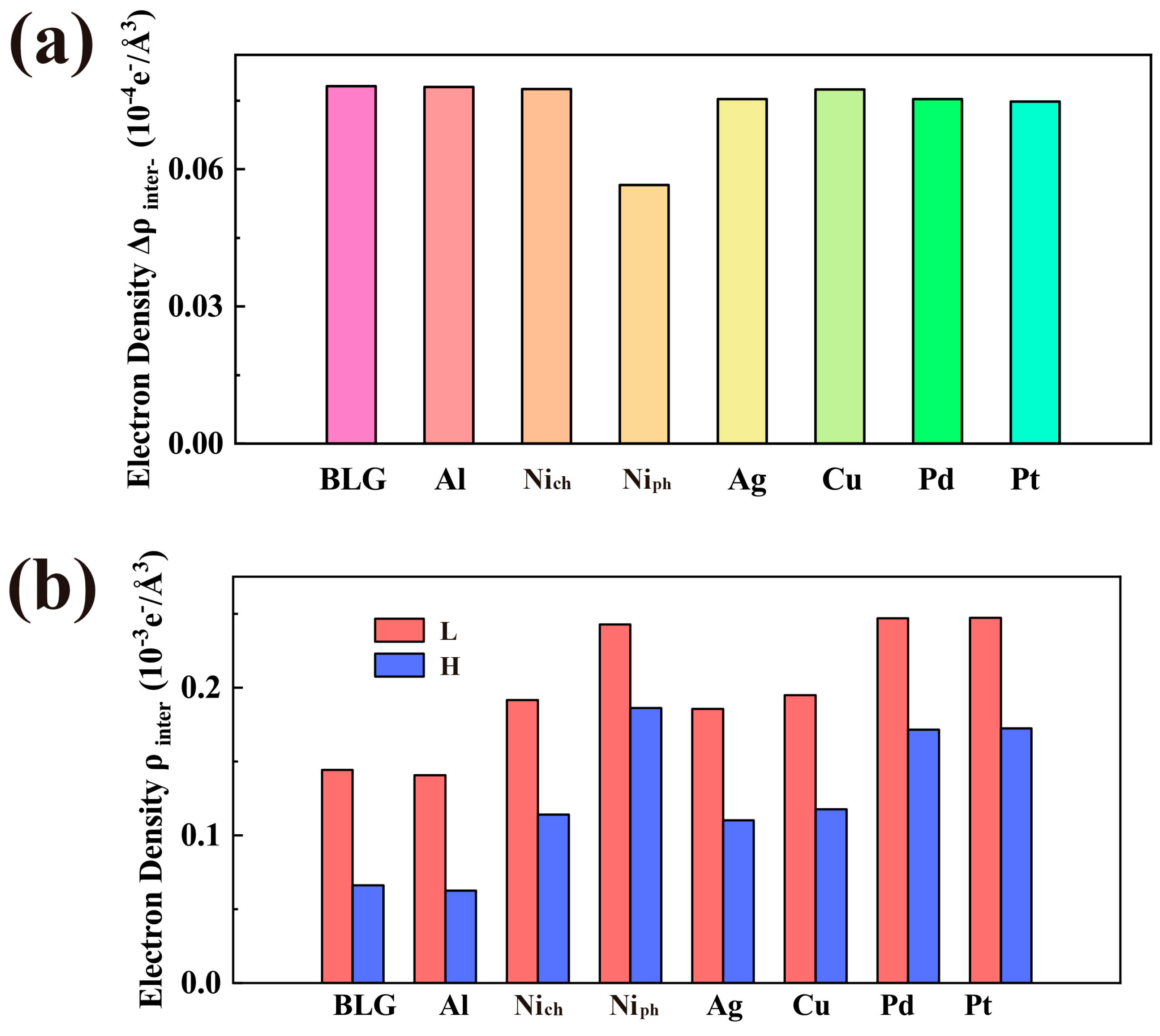
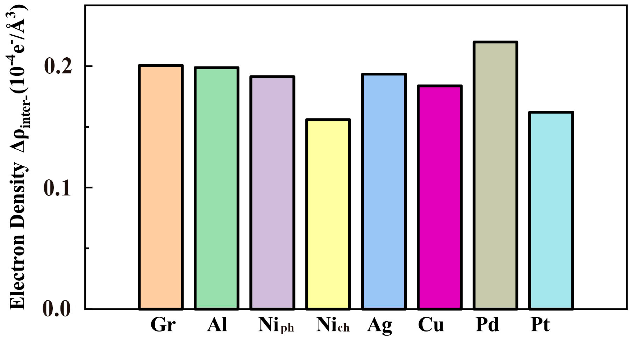
To quantify the variations in electron density between the most stable and unstable sites, we used the method reported in the previous literature (see Appendix D for more details) [44]. The electron density and fluctuation between Gr–Gr layers for both sites are exhibited in Figure 5. As shown in the curves of the total electron density (see Figure A7 in Appendix F) and the maps of electron density difference (see Figure A8 in Appendix F), the quantified results in Figure 5b demonstrate that the introduction of substrates changes the electron density between the Gr–Gr layer in both sites. In particular, the presence of Nich substrate leads to the highest electron density between Gr–Gr layers, which aligns with its maximum bonding energy (see Table 1). Interestingly, for different metal substrates, a positive correlation exists between the fluctuations in electron density (see Figure 5b) and the energy barriers (see Figure 2b) at the sliding interface. Similarly, the presence of Nich substrate significantly weakens , and thus, the Gr-Gr/Nich model has the minimum sliding barrier. A similar conclusion can also be obtained for the Tip-Gr/Metal system (see Figure A9 in Appendix F). The substrate in the Tip-Gr/Metal system has a significantly greater influence on the interfacial charge, compared with the substrate in the Gr-Gr/Metal system. This difference lies in the different degrees of charge transfer between the graphene and its substrates. Thus, we conclude that the regulation effect of a substrate on friction at the Gr–Gr or Tip–Gr interface is due to its ability to modulate the electron density fluctuation.
Figure 5.
The impacts of substrate materials on the charge distribution at the Gr–Gr interlayer. (a) Differences in interlayer electron density () between L and H sites, and (b) interlayer charge densities () at L and H sites in Gr-Gr/Metal system. H and L represent the highest and lowest energy sites.
4. Conclusions
In this work, the effects of metal substrates on the friction between two graphene monolayers or between a metal tip and a graphene monolayer have been investigated through simulations of two nanotribological systems by carrying out first-principles computations. It follows from analysis of the simulation results that the sliding energy barriers of the two systems can be affected by the substrates involved. Consequently, nanofriction is, in general, influenced by the presence of a substrate. In particular, among all the substrates studied, the chemisorbed Ni substrate (Nich) exhibits a large ability to reduce friction. The interfacial binding is also affected by the existence of a substrate. It is important to underline the important conclusion that the interfacial electron density change produced by a substrate is responsible for its effects on friction.
The results obtained in the present work assist in obtaining a better understanding and interpretation of available relevant experimental results on nanofriction. They can be useful in designing micro/nano electromechanical systems (MEMS/NEMES) to improve their tribological behavior.
Author Contributions
H.F. and Z.C.: methodology, data curation, formal analysis, writing—original and revised manuscript and editing; D.L.: support for calculation scripts; T.Y.: supervision; Z.L.: support for software of first-principles calculations; Q.H.: editing, supervision, funding acquisition, and review. All authors have read and agreed to submit the revised manuscript.
Funding
This work was financially supported by the National Natural Science Foundation of China (Grant Nos. 11890673, VP21ZR1102Y19004).
Data Availability Statement
Not applicable.
Conflicts of Interest
The authors declare no conflict of interest.
Appendix A. The Binding of Gr-Gr/Metal and Tip-Gr/Metal
The distance of adsorption, the binding energy (move/cell) and the lattice constant an of graphene after matching vary with the metal substrate used. The relevant variations are shown in Table A1. These results are in good agreement with previous reports [11,30]. Copper atoms, which are commonly used in Atomic Force Microscope (AFM) experiments, were chosen in the present work as forming the probe in the Tip-Gr/Metal system.

Table A1.
Parameters for the binding of graphene to different metal substrates: distance of adsorption (Å), binding energy (meV/atom) and lattice constant a of graphene after matching (Å).
Table A1.
Parameters for the binding of graphene to different metal substrates: distance of adsorption (Å), binding energy (meV/atom) and lattice constant a of graphene after matching (Å).
| Parameter | Substrate Materials | |||||||
|---|---|---|---|---|---|---|---|---|
| Al | Cu | Pd | Pt | Ag | Niph | Nich | None | |
| Distance of adsorption (Å) | 3.45 | 3.14 | 2.34 | 3.3 | 3.34 | 3.32 | 2.04 | / |
| (meV/atom) | 26 | 34 | 64 | 35 | 42 | 55 | 117 | / |
| Lattice constant of graphene after matching (Å) | 2.44 | 2.43 | 2.45 | 2.38 | 2.39 | 2.45 | 2.45 | 2.46 |
The bonding between the top (or tip) and the lower graphene surface is determined by the binding energy (or ):
where , and represent the total energies of the Gr-Gr (or Tip-Gr), top graphene (or tip), lower graphene, Gr-Gr/Metal (or Tip-Gr/Metal)and Gr/Metal, respectively, with the symbol being the area of the cell.
The bonding between the graphene and the metal substrates is determined by the binding energy :
where and represent the total energies of the Gr/Metal, graphene and metal substrate, respectively; the symbol indicates the number of carbon atoms in the cell.
Appendix B. The Sliding Path Adopted for Simulations
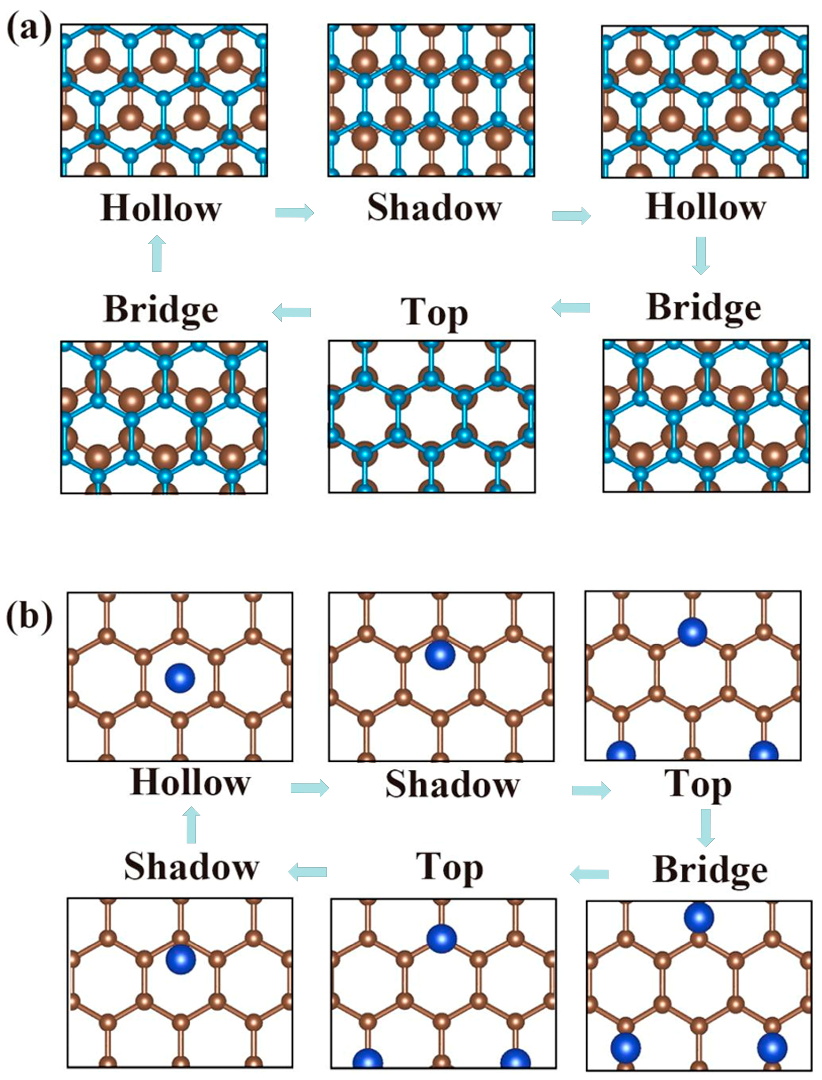
For the simulations of Gr-Gr/Metal and Tip-Gr/Metal, all of the sliding paths chosen are shown in the following figure. As the lattice is periodic, the energy barriers of the sliding paths also exhibit this property. The probe in the Tip-Gr/Metal system consists of two copper atoms The blue or brown spheres represents the carbon atoms in the upper or lower layers of the graphene bilayer in Figure A1a. In Figure A1b, the blue and brown balls represent the copper atoms and the carbon atoms, respectively.
Figure A1.
Schematic diagram of sliding paths. (a) A top graphene layer sliding on a lower graphene surface. (b) A probe sliding on a graphene surface. The sliding passes through four high symmetry sites: Hollow, Shadow, Top and Bridge. Here, the substrate is removed for a better visualization.
Figure A1.
Schematic diagram of sliding paths. (a) A top graphene layer sliding on a lower graphene surface. (b) A probe sliding on a graphene surface. The sliding passes through four high symmetry sites: Hollow, Shadow, Top and Bridge. Here, the substrate is removed for a better visualization.
Appendix C. Fluctuations in Energy
The change in the friction force can be observed from PES. Here, we show the results concerning PES for the Gr-Gr/Metal or Tip-Gr/Metal system in the following cases: no substrate, or Al, Ag, Cu, Pd, Pt, Nich and Niph substrates. The value of a point on the PES is obtained by subtracting the energy of the lowest energy in the entire PES from the energy corresponding to that point. We also show the maximum for the Tip-Gr/Metal system.
Figure A2.
The potential energy surface (PES) for various Gr-Gr/Metal systems. The lower Gr surface supported by (a) nothing, or (b) Al, (c) Ag, (d) Cu, (e) Pd, (f) Pt, (g) Nich and (h) Niph substrates. In these panels, the red dashed line indicates the sliding path, and the parameter is the in-plane lattice constant of the Gr surface. The values of are specified in Table A1. The unit of potential energy is meV/Å2.

Figure A3.
The potential energy surface (PES) for various Tip-Gr/Metal systems. The Gr surface supported by (a) nothing, or (b) Al, (c) Ag, (d) Cu, (e) Pd, (f) Pt, (g) Nich and (h) Niph substrates. In these panels, the red dashed line indicates the sliding path, and the parameter is the in-plane lattice constant of the Gr surface. The values of are given in Table A1. The unit of potential energy is meV/atom.

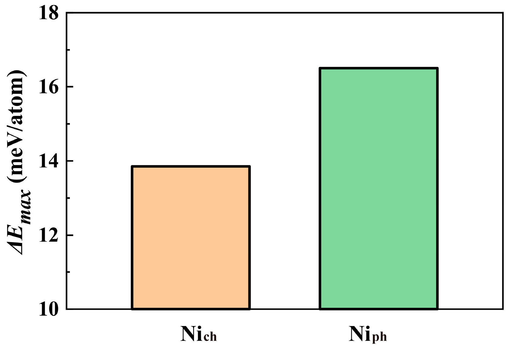
Figure A4.
The maximum value of the sliding energy barriers of the Tip-Gr/Metal system with a Nich or Niph substrate.
Figure A4.
The maximum value of the sliding energy barriers of the Tip-Gr/Metal system with a Nich or Niph substrate.
Appendix D. Calculations of Electron Density Difference
To calculate the binding between the graphene layer and the metal substrates, we used five substrates. In all calculations relating to the Ni substrate, we considered orbital spin coupling. First, we fixed the bottom two basal atoms while the others were relaxed. In the Gr-Gr/Metal or Tip-Gr/Metal system, we retained only the upper three layers of the substrate for computational efficiency. The normal force is obtained by deriving as a function of the separation z of the L site (Figure A1b in Appendix B) [47], i.e.,
For the calculation of the electron density, we use the same method as in the previous report [44]. The electron density difference is defined as
where , and are the electron densities of the total system, top layer graphene in Gr-Gr/Metal (or probe in Tip-Gr/Metal), and bottom layer graphene plus the metal substrate, respectively, along the z-axis; represents the area of the supercell. According to the domain occupied by the interlayer zone [44], the electron density difference between layers is calculated by
Thus, the fluctuations in electron density are revealed by
Appendix E. Stackings in the Gr-Gr/Metal System
To achieve a lattice matching, supercells were used for Ni and Cu in combination with Gr, while supercells are employed for Al, Pd, Ag and Pt (see Figure A2 in Appendix C). For Ni and Cu substrates, top-fcc is the most suitable configuration. The energy maximum, local minimum and global minimum points appear in the first configuration. On the basis of these two configurations after the optimization, we placed graphene or probes to build our Gr-Gr/Metal or Tip-Gr/Metal system. The spheres of the one top layer in Figure A5 and of the two top layers in Figure A6 represent the carbon atoms and the other spheres are the atoms of the metal substrate.
Figure A5.
The adsorbed structures of the Gr surface on a metal substrate. (a) Top and (c) side views of Gr surface on Ni and Cu substrate models with top-fcc configuration. (b) Top and (d) side views of graphene on Al, Ag, Pd and Pt substrate models with configuration.
Figure A5.
The adsorbed structures of the Gr surface on a metal substrate. (a) Top and (c) side views of Gr surface on Ni and Cu substrate models with top-fcc configuration. (b) Top and (d) side views of graphene on Al, Ag, Pd and Pt substrate models with configuration.

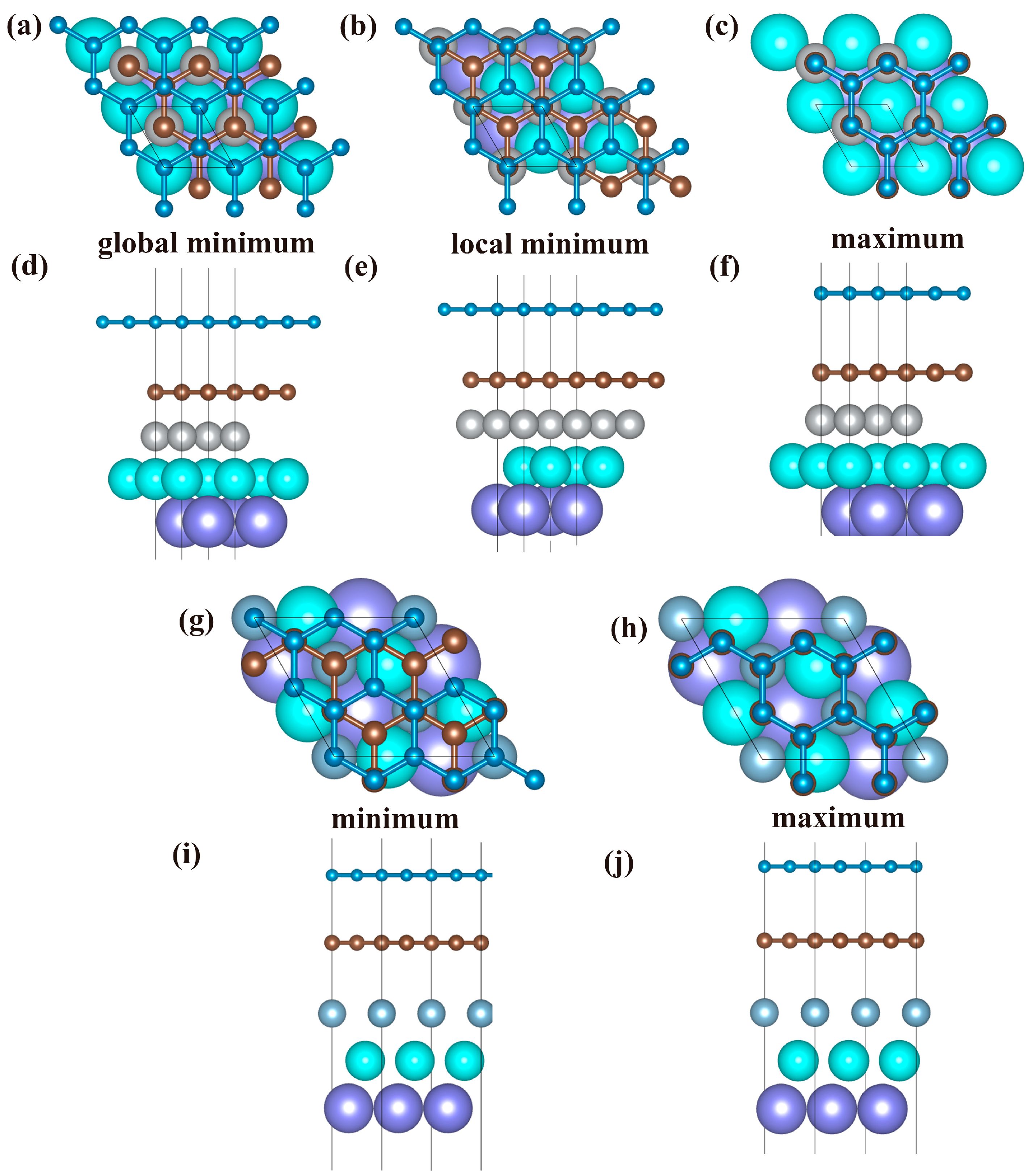
Figure A6.
In the Gr-Gr/Metal system, the top views (a–c,g,h) and side views (d–f,i,j) represent the structures associated with the energy extremes that occur during the sliding process. For the top-fcc configuration, (a,d) show the structure corresponding to the global minimum of energy, (b,e) show the structure with the local minimum of energy, and (c,f) show the structure producing the maximum of energy. For the configuration, (g,i) show the structure with the minimum of energy, and (h,j) show the structure exhibiting the maximum of energy.
Appendix F. Electron Density Analysis
We show the results for the total electron density in the Gr-Gr/Metal system through electron density calculations at the L site (See Appendix D for the detailed calculations). The strength of the bonding is reflected in the charge strength between the lower graphene layer and the top metal substrate. We show the H and L site differential electron density (See Figure 5 for specific quantified data).
Figure A7.
Schematic of the total electron density of the Gr-Gr/Metal system. Projections of total electron density on the z-axis when the lower Gr surface is supported by (a) nothing, or (b) Al, (c) Ag, (d) Cu, (e) Pd, (f) Pt, (g) Nich and (h) Niph substrates.
Figure A7.
Schematic of the total electron density of the Gr-Gr/Metal system. Projections of total electron density on the z-axis when the lower Gr surface is supported by (a) nothing, or (b) Al, (c) Ag, (d) Cu, (e) Pd, (f) Pt, (g) Nich and (h) Niph substrates.
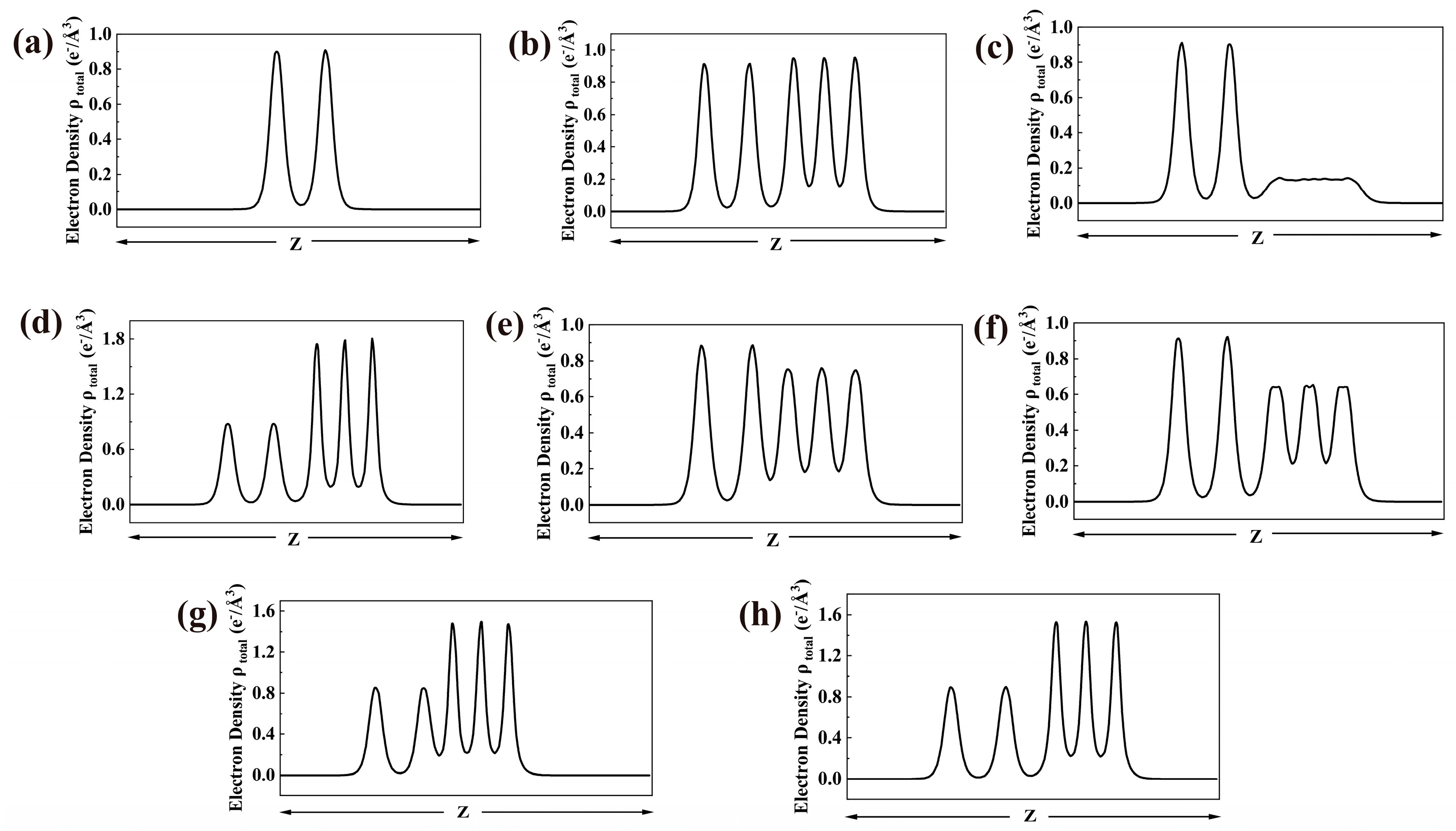
Figure A8.
Maps of the electron density difference. The base graphene is set on (a,e) no substrate, (b,f) Al substrate, (c,g) Nich substrate and (d,h) Niph substrate. The conformations of the bilayer graphene with (a–d) L and (e–h) H sites (see Figure A1 in Appendix B). Note: red and blue indicate electron accumulation and depletion, respectively.
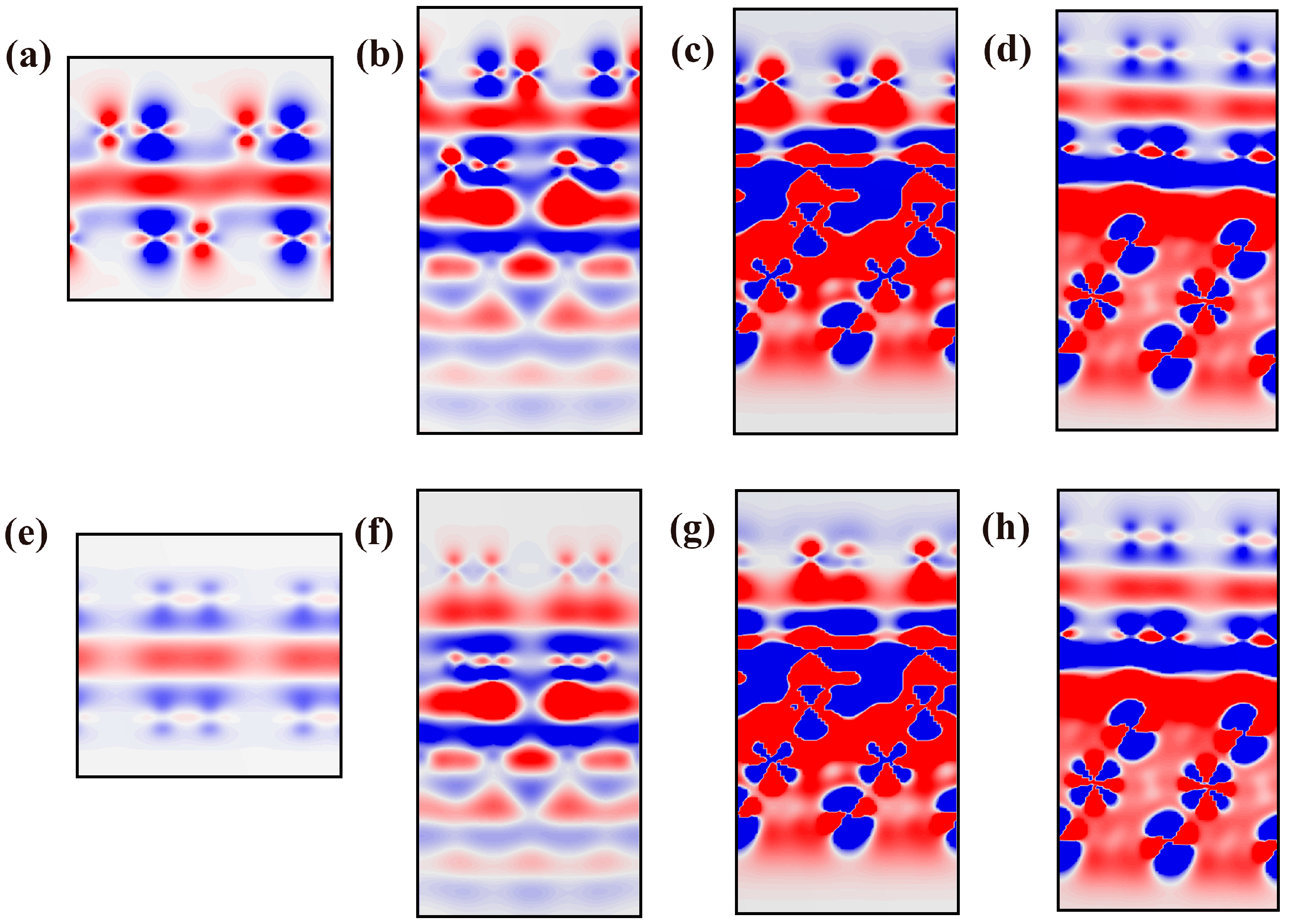
Figure A9.
The impacts of substrate materials on the charge distribution at the Tip–Gr interlayer. Differences in interlayer electron density () between L and H sites in the Tip-Gr/Metal system.
Figure A9.
The impacts of substrate materials on the charge distribution at the Tip–Gr interlayer. Differences in interlayer electron density () between L and H sites in the Tip-Gr/Metal system.
References
- Zhu, J.; Liu, X.; Shi, Q.; He, T.; Sun, Z.; Guo, X.; Liu, W.; Sulaiman, O.B.; Dong, B.; Lee, C. Development trends and perspectives of future sensors and MEMS/NEMS. Micromachines 2019, 11, 7. [Google Scholar] [CrossRef]
- Kim, S.H.; Asay, D.B.; Dugger, M.T. Nanotribology and MEMS. Nano Today 2007, 2, 22–29. [Google Scholar] [CrossRef]
- Feng, B.; Sugino, O.; Liu, R.-Y.; Zhang, J.; Yukawa, R.; Kawamura, M.; Iimori, T.; Kim, H.; Hasegawa, Y.; Li, H. Dirac fermions in borophene. Phys. Rev. Lett. 2017, 118, 096401. [Google Scholar] [CrossRef] [PubMed]
- Spear, J.C.; Ewers, B.W.; Batteas, J.D. 2D-nanomaterials for controlling friction and wear at interfaces. Nano Today 2015, 10, 301–314. [Google Scholar] [CrossRef]
- Dietzel, D.; Brndiar, J.; Stich, I.; Schirmeisen, A. Limitations of structural superlubricity: Chemical bonds versus contact size. ACS Nano 2017, 11, 7642–7647. [Google Scholar] [CrossRef] [PubMed]
- Liu, P.; Xie, J.; Wang, A.; Ma, D.; Mao, Z. First-principles prediction of enhancing graphene/Al interface bonding strength by graphene doping strategy. Appl. Surf. Sci. 2020, 517, 146040. [Google Scholar] [CrossRef]
- Zhang, J.; Gao, X.; Xu, Q.; Ma, T.; Hu, Y.; Luo, J. Atomistic insights into friction and wear mechanisms of graphene oxide. Appl. Surf. Sci. 2021, 546, 149130. [Google Scholar] [CrossRef]
- Wang, L.; Zhou, X.; Ma, T.; Liu, D.; Gao, L.; Li, X.; Zhang, J.; Hu, Y.; Wang, H.; Dai, Y. Superlubricity of a graphene/MoS 2 heterostructure: A combined experimental and DFT study. Nanoscale 2017, 9, 10846–10853. [Google Scholar] [CrossRef]
- Song, Y.; Mandelli, D.; Hod, O.; Urbakh, M.; Ma, M.; Zheng, Q. Robust microscale superlubricity in graphite/hexagonal boron nitride layered heterojunctions. Nat. Mater. 2018, 17, 894–899. [Google Scholar] [CrossRef]
- Zhang, Z.; Yang, Y.; Gao, G.; Yakobson, B.I. Two-dimensional boron monolayers mediated by metal substrates. Angew. Chem. 2015, 127, 13214–13218. [Google Scholar] [CrossRef]
- Khomyakov, P.; Giovannetti, G.; Rusu, P.; Brocks, G.v.; Van den Brink, J.; Kelly, P.J. First-principles study of the interaction and charge transfer between graphene and metals. Phys. Rev. B 2009, 79, 195425. [Google Scholar] [CrossRef]
- Lee, C.; Li, Q.; Kalb, W.; Liu, X.-Z.; Berger, H.; Carpick, R.W.; Hone, J. Frictional characteristics of atomically thin sheets. Science 2010, 328, 76–80. [Google Scholar] [CrossRef] [PubMed]
- Zheng, X.; Gao, L.; Yao, Q.; Li, Q.; Zhang, M.; Xie, X.; Qiao, S.; Wang, G.; Ma, T.; Di, Z. Robust ultra-low-friction state of graphene via moiré superlattice confinement. Nat. Commun. 2016, 7, 13204. [Google Scholar] [CrossRef]
- Jiang, J.-W.; Wang, J.-S.; Li, B. Young’s modulus of graphene: A molecular dynamics study. Phys. Rev. B 2009, 80, 113405. [Google Scholar] [CrossRef]
- Ji, E.; Kim, M.J.; Lee, J.-Y.; Sung, D.; Kim, N.; Park, J.-W.; Hong, S.; Lee, G.-H. Substrate effect on doping and degradation of graphene. Carbon 2021, 184, 651–658. [Google Scholar] [CrossRef]
- Peng, B.; Zhang, H.; Shao, H.; Xu, Y.; Zhang, R.; Zhu, H. The electronic, optical, and thermodynamic properties of borophene from first-principles calculations. J. Mater. Chem. C 2016, 4, 3592–3598. [Google Scholar] [CrossRef]
- Munther, M.; Palma, T.; Beheshti, A.; Davami, K. Substrate-regulated nanoscale friction of graphene. Mater. Lett. 2018, 221, 54–56. [Google Scholar] [CrossRef]
- Qi, Y.; Liu, J.; Dong, Y.; Feng, X.-Q.; Li, Q. Impacts of environments on nanoscale wear behavior of graphene: Edge passivation vs. substrate pinning. Carbon 2018, 139, 59–66. [Google Scholar] [CrossRef]
- Zeng, X.; Peng, Y.; Lang, H. A novel approach to decrease friction of graphene. Carbon 2017, 118, 233–240. [Google Scholar] [CrossRef]
- Shi, B.; Gan, X.; Lang, H.; Zou, K.; Wang, L.; Sun, J.; Lu, Y.; Peng, Y. Ultra-low friction and patterning on atomically thin MoS2 via electronic tight-binding. Nanoscale 2021, 13, 16860–16871. [Google Scholar] [CrossRef]
- Rajesh, C.; Majumder, C. Interaction of gold clusters with graphene and graphene layer over Ni(111) surface: A density functional study. Appl. Surf. Sci. 2019, 469, 917–922. [Google Scholar] [CrossRef]
- Lu, Y.; Xiao, C.; Jiang, Y.; Tang, C.; Chen, L.; Sun, J.; Qian, L. Nanoscale Wear Triggered by Stress-Driven Electron Transfer. Nano Lett. 2023, 23, 8842–8849. [Google Scholar] [CrossRef] [PubMed]
- Tang, C.; Jiang, Y.; Chen, L.; Sun, J.; Liu, Y.; Shi, P.; Aguilar-Hurtado, J.Y.; Rosenkranz, A.; Qian, L. Layer-Dependent Nanowear of Graphene Oxide. ACS Nano 2023, 17, 2497–2505. [Google Scholar] [CrossRef] [PubMed]
- Sun, J.; Chang, K.; Mei, D.; Lu, Z.; Pu, J.; Xue, Q.; Huang, Q.; Wang, L.; Du, S. Mutual identification between the pressure-induced superlubricity and the image contrast inversion of carbon nanostructures from AFM technology. J. Phys. Chem. Lett. 2019, 10, 1498–1504. [Google Scholar] [CrossRef]
- Schneiderbauer, M.; Emmrich, M.; Weymouth, A.J.; Giessibl, F.J. CO tip functionalization inverts atomic force microscopy contrast via short-range electrostatic forces. Phys. Rev. Lett. 2014, 112, 166102. [Google Scholar] [CrossRef]
- Lee, A.J.; Sakai, Y.; Chelikowsky, J.R. Simulating contrast inversion in atomic force microscopy imaging with real-space pseudopotentials. Phys. Rev. B 2017, 95, 081401. [Google Scholar] [CrossRef]
- Segall, M.; Lindan, P.J.; Probert, M.a.; Pickard, C.J.; Hasnip, P.J.; Clark, S.; Payne, M. First-principles simulation: Ideas, illustrations and the CASTEP code. J. Phys. Condens. Matter 2002, 14, 2717. [Google Scholar] [CrossRef]
- Clark, S.J.; Segall, M.D.; Pickard, C.J.; Hasnip, P.J.; Probert, M.I.; Refson, K.; Payne, M.C. First principles methods using CASTEP. Z. Krist.-Cryst. Mater. 2005, 220, 567–570. [Google Scholar] [CrossRef]
- Vanin, M.; Mortensen, J.J.; Kelkkanen, A.; Garcia-Lastra, J.M.; Thygesen, K.S.; Jacobsen, K.W. Graphene on metals: A van der Waals density functional study. Phys. Rev. B 2010, 81, 081408. [Google Scholar] [CrossRef]
- Fuentes-Cabrera, M.; Baskes, M.I.; Melechko, A.V.; Simpson, M.L. Bridge structure for the graphene/Ni (111) system: A first principles study. Phys. Rev. B 2008, 77, 035405. [Google Scholar] [CrossRef]
- Bhushan, B. Nanotribology and Nanomechanics: An Introduction; Springer: Berlin/Heidelberg, Germany, 2008. [Google Scholar]
- Paolicelli, G.; Tripathi, M.; Corradini, V.; Candini, A.; Valeri, S. Nanoscale frictional behavior of graphene on SiO2 and Ni(111) substrates. Nanotechnology 2015, 26, 055703. [Google Scholar] [CrossRef]
- Tripathi, M.; Awaja, F.; Paolicelli, G.; Bartali, R.; Iacob, E.; Valeri, S.; Ryu, S.; Signetti, S.; Speranza, G.; Pugno, N.M. Tribological characteristics of few-layer graphene over Ni grain and interface boundaries. Nanoscale 2016, 8, 6646–6658. [Google Scholar] [CrossRef]
- Chen, J.; Li, J.; Xiong, D.; He, Y.; Ji, Y.; Qin, Y. Preparation and tribological behavior of Ni-graphene composite coating under room temperature. Appl. Surf. Sci. 2016, 361, 49–56. [Google Scholar] [CrossRef]
- Liu, Y.; Zheng, F.; Wu, Y.; Koch, C.C.; Han, P.; Zhang, C.; Liu, Y.; Zhang, Y. Grain refinement induced friction reduction and anti-wear performances of electrodeposited graphene/Ni composites with low content reduced graphene oxide. J. Alloys Compd. 2020, 826, 154080. [Google Scholar] [CrossRef]
- Dong, Y.r.; Sun, W.c.; Liu, X.j.; Ma, M.; Zhang, Y.g.; Liu, Y.w. Electrophoretic-Deposition of Graphene and Microstructure and Friction Behavior of Ni–Graphene Composite Coatings. Adv. Eng. Mater. 2019, 21, 1900327. [Google Scholar] [CrossRef]
- Sun, J.; Zhang, Y.; Lu, Z.; Li, Q.; Xue, Q.; Du, S.; Pu, J.; Wang, L. Superlubricity enabled by pressure-induced friction collapse. J. Phys. Chem. Lett. 2018, 9, 2554–2559. [Google Scholar] [CrossRef] [PubMed]
- Gao, J.; Luedtke, W.; Gourdon, D.; Ruths, M.; Israelachvili, J.; Landman, U. Frictional Forces and Amontons’ Law: From the Molecular to the Macroscopic Scale. J. Phys. Chem. B 2004, 108, 3410–3425. [Google Scholar] [CrossRef]
- Cai, W.; Trefs, J.L.; Hugel, T.; Balzer, B.N. Anisotropy of π–π Stacking as Basis for Superlubricity. ACS Mater. Lett. 2022, 5, 172–179. [Google Scholar] [CrossRef]
- Liu, Y.; Jiang, Y.; Sun, J.; Wang, L.; Liu, Y.; Chen, L.; Zhang, B.; Qian, L. Durable superlubricity of hydrogenated diamond-like carbon film against different friction pairs depending on their interfacial interaction. Appl. Surf. Sci. 2021, 560, 150023. [Google Scholar] [CrossRef]
- Zhao, S.; Zhang, Z.; Wu, Z.; Liu, K.; Zheng, Q.; Ma, M. The impacts of adhesion on the wear property of graphene. Adv. Mater. Interfaces 2019, 6, 1900721. [Google Scholar] [CrossRef]
- Giovannetti, G.; Khomyakov, P.A.; Brocks, G.; Karpan, V.M.; van den Brink, J.; Kelly, P.J. Doping graphene with metal contacts. Phys. Rev. Lett. 2008, 101, 026803. [Google Scholar] [CrossRef] [PubMed]
- Hamada, I.; Otani, M. Comparative van der Waals density-functional study of graphene on metal surfaces. Phys. Rev. B 2010, 82, 153412. [Google Scholar] [CrossRef]
- Cheng, Z.; Sun, J.; Zhang, B.; Lu, Z.; Ma, F.; Zhang, G.; Xue, Q. Strain effects of vertical separation and horizontal sliding in commensurate two-dimensional homojunctions. J. Phys. Chem. Lett. 2020, 11, 5815–5822. [Google Scholar] [CrossRef] [PubMed]
- Wolloch, M.; Levita, G.; Restuccia, P.; Righi, M. Interfacial charge density and its connection to adhesion and frictional forces. Phys. Rev. Lett. 2018, 121, 026804. [Google Scholar] [CrossRef] [PubMed]
- Zhang, B.; Zhang, G.; Cheng, Z.; Ma, F.; Lu, Z. Atomic-scale friction adjustment enabled by doping-induced modification in graphene nanosheet. Appl. Surf. Sci. 2019, 483, 742–749. [Google Scholar] [CrossRef]
- Zhong, W.; Tomanek, D. First-principles theory of atomic-scale friction. Phys. Rev. Lett. 1990, 64, 3054. [Google Scholar] [CrossRef] [PubMed]
Figure 1.
Conceptual diagrams of the calculation models. (a) Gr-Gr/Metal system comprising a top Gr layer sliding on a lower Gr layer supported by a triple-atom layer metal substrate. (b) Tip-Gr/Metal system consisting of a diatomic probe sliding on a Gr layer supported by a triple-atom layer metal substrate.
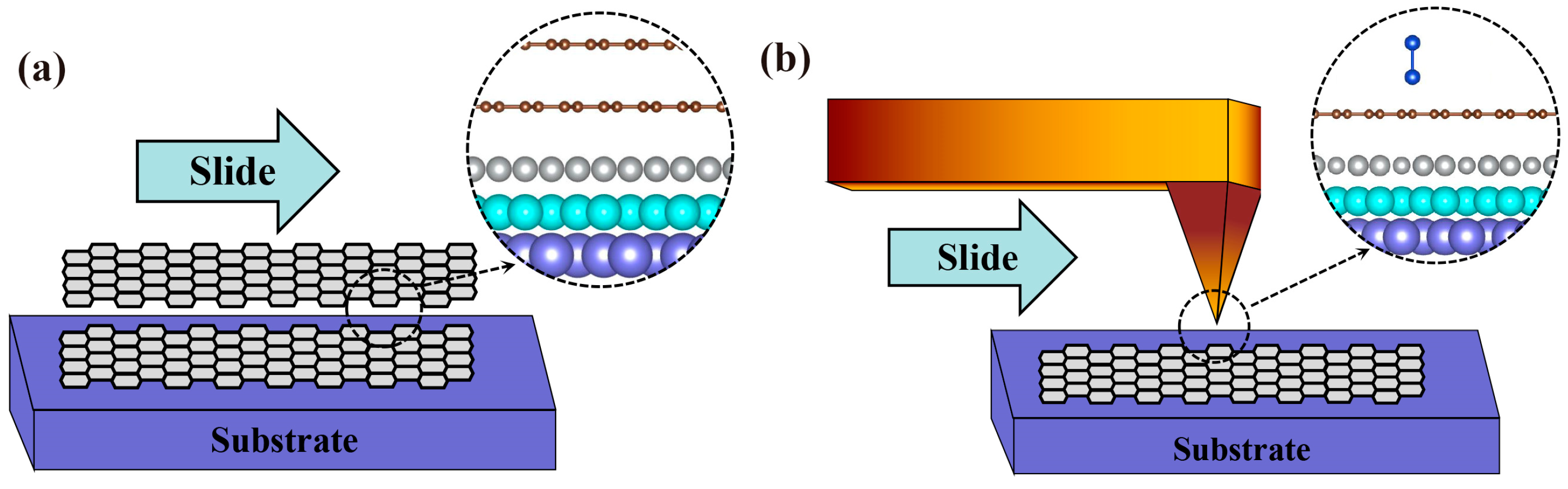
Figure 2.
The sliding energy barriers of Gr-Gr/Metal and Tip-Gr/Metal systems. (a) A top Gr layer and (c) a diatomic probe sliding on the surface of Gr supported by diverse metal substrates. The maximum values of sliding energy barriers in (b) Gr-Gr/Metal systems and (d) Tip-Gr/Metal systems. The units are converted to meV/Å2 or meV/atom for ease of comparison. The sliding distance is expressed in terms of the lattice constant a, the values of which are shown in Table A1. H and L represent the highest and lowest energy sites.
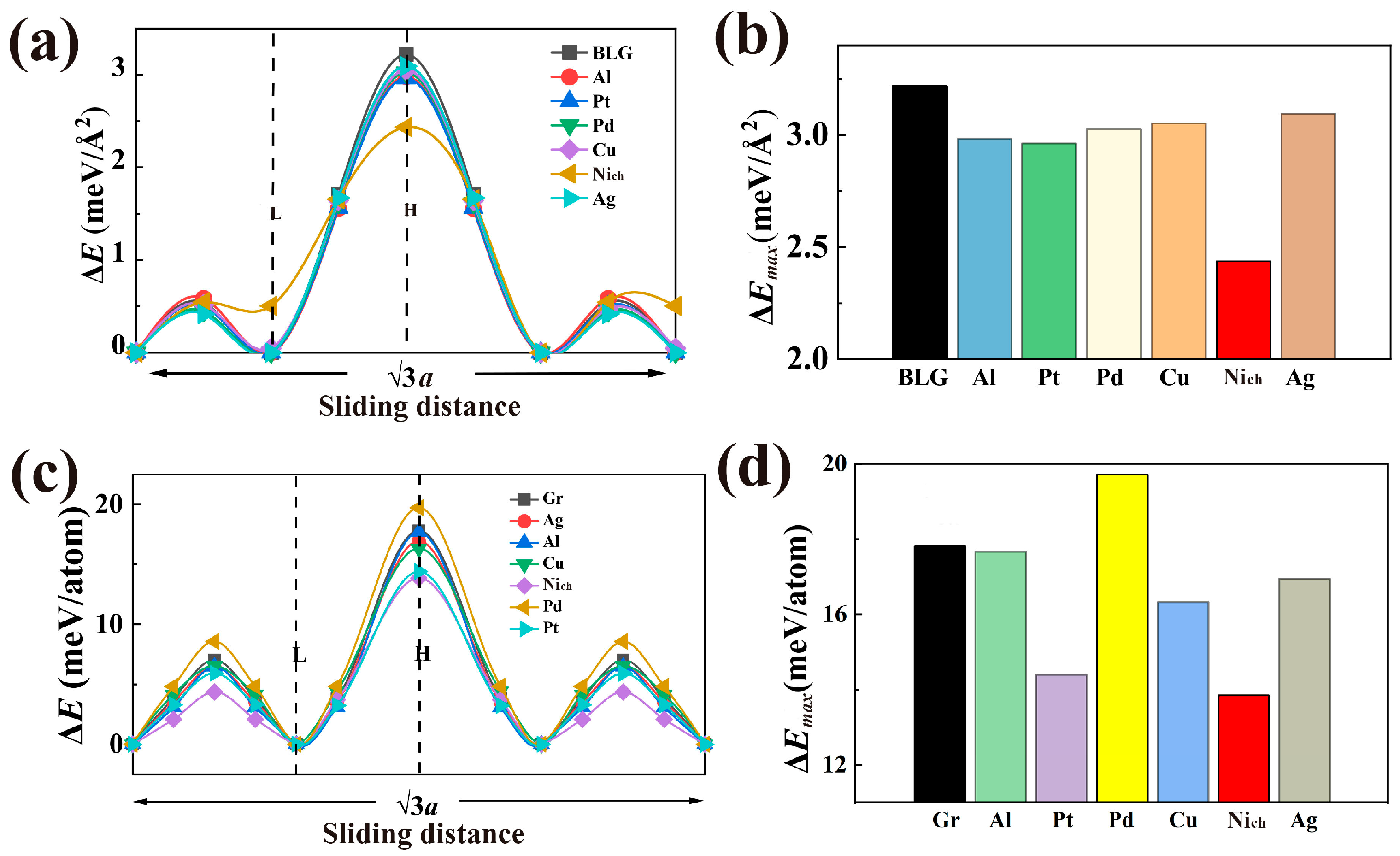
Figure 3.
Adsorption types of a Gr surface on the Ni substrate and their effects on the sliding energy barriers. (a) The dependence of adsorption energy on binding distance between the graphene and Ni substrate. (b) The sliding energy barriers for a top Gr layer sliding on another Gr surface physically (Niph) or chemically (Nich), adsorbed upon a Ni substrate. The sliding distance is expressed in terms of the lattice constant a, the values of which are shown in Table A1. H and L represent the highest and lowest energy sites.
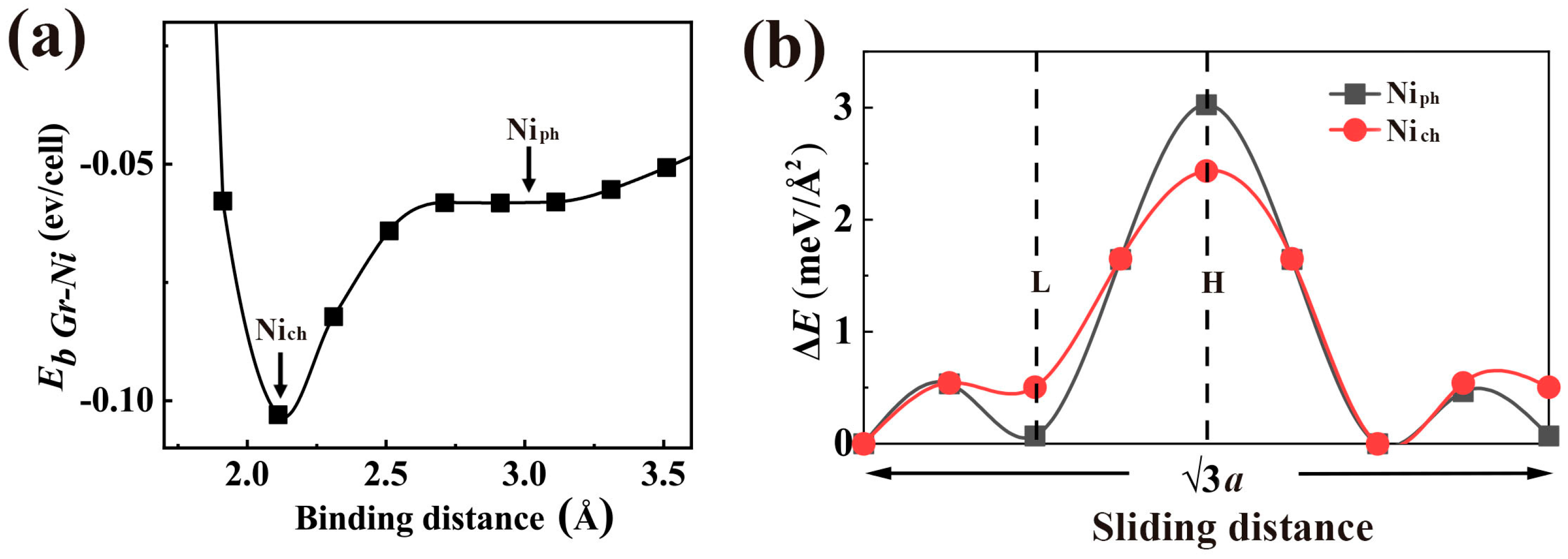
Figure 4.
The dependence of energy barrier on the applied load in the Tip-Gr/Metal system.
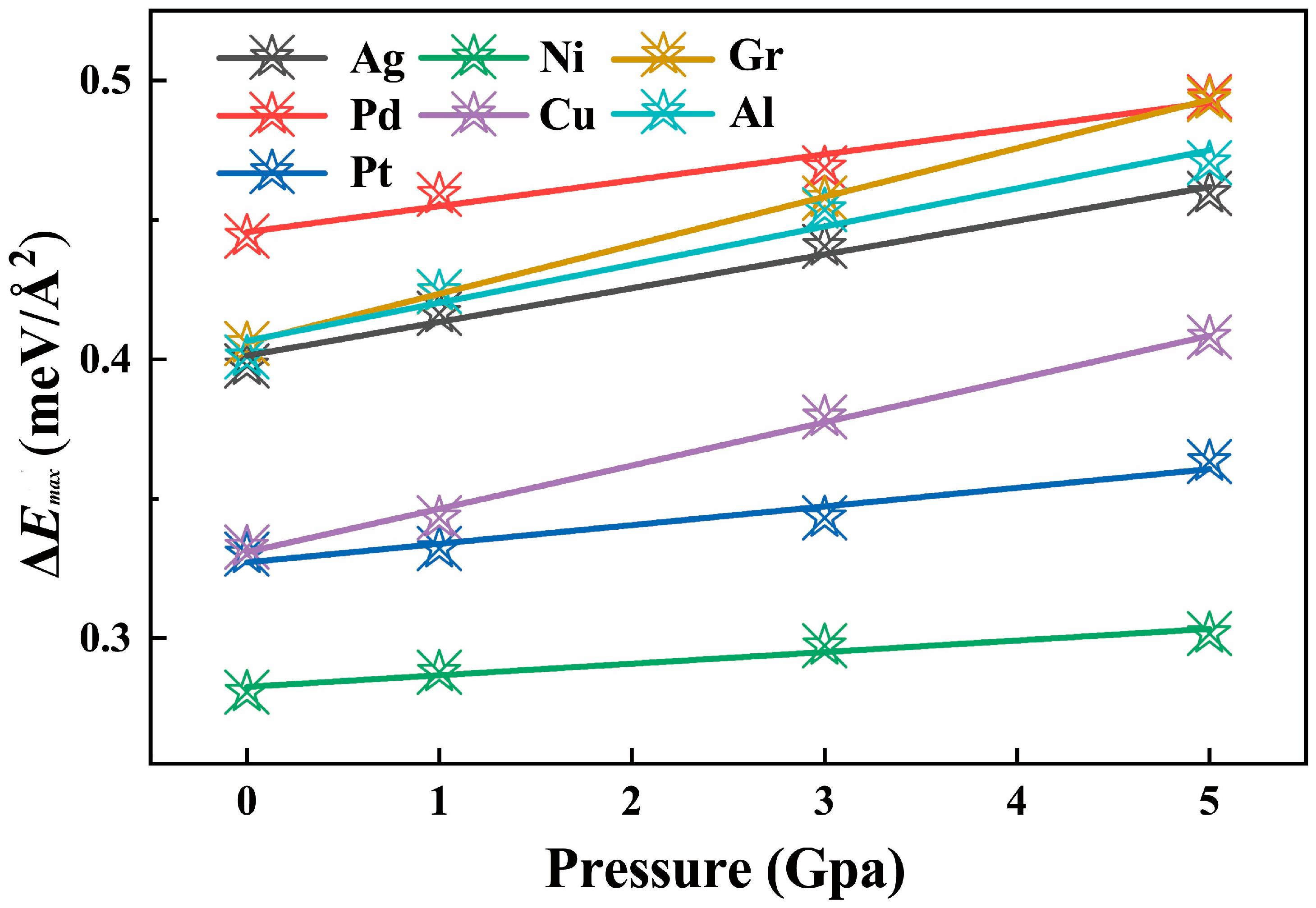
Table 1.
The binding energies and binding distances between the upper graphene layer or diatomic probe and the lower graphene layer in Gr-Gr/Metal or Tip-Gr/Metal systems.
Table 1.
The binding energies and binding distances between the upper graphene layer or diatomic probe and the lower graphene layer in Gr-Gr/Metal or Tip-Gr/Metal systems.
| Gr-Gr/Metal | (meV/Å2) | (Å) |
|---|---|---|
| Without substrate | 0.0251 | 3.325 |
| Ag | 0.0239 | 3.338 |
| Al | 0.0249 | 3.303 |
| Cu | 0.0236 | 3.324 |
| Ni | 0.0616 | 3.324 |
| Pd | 0.0266 | 3.273 |
| Pt | 0.0251 | 3.308 |
| Tip-Gr/Metal | (eV/Å2) | (Å) |
| Without substrate | 0.2192 | 1.968 |
| Ag | 0.2322 | 1.972 |
| Al | 0.2142 | 1.978 |
| Cu | 0.2310 | 1.972 |
| Ni | 0.2016 | 2.011 |
| Pd | 0.2188 | 2.035 |
| Pt | 0.2373 | 2.001 |
Disclaimer/Publisher’s Note: The statements, opinions and data contained in all publications are solely those of the individual author(s) and contributor(s) and not of MDPI and/or the editor(s). MDPI and/or the editor(s) disclaim responsibility for any injury to people or property resulting from any ideas, methods, instructions or products referred to in the content. |
© 2023 by the authors. Licensee MDPI, Basel, Switzerland. This article is an open access article distributed under the terms and conditions of the Creative Commons Attribution (CC BY) license (https://creativecommons.org/licenses/by/4.0/).
Share and Cite
MDPI and ACS Style
Feng, H.; Cheng, Z.; Long, D.; Yang, T.; Lu, Z.; He, Q. How Do Substrates Affect the Friction on Graphene at the Nanoscale? Lubricants 2023, 11, 465. https://doi.org/10.3390/lubricants11110465
AMA Style
Feng H, Cheng Z, Long D, Yang T, Lu Z, He Q. How Do Substrates Affect the Friction on Graphene at the Nanoscale? Lubricants. 2023; 11(11):465. https://doi.org/10.3390/lubricants11110465
Chicago/Turabian StyleFeng, Haochen, Ziwen Cheng, Dongxu Long, Tingting Yang, Zhibin Lu, and Qichang He. 2023. "How Do Substrates Affect the Friction on Graphene at the Nanoscale?" Lubricants 11, no. 11: 465. https://doi.org/10.3390/lubricants11110465
Note that from the first issue of 2016, this journal uses article numbers instead of page numbers. See further details here.