Abstract
In smart coatings designed for friction units operating in wide temperature ranges, the material reacts to heating by changing its frictional properties. Appropriate experimental studies are available. In this paper, a model is proposed for studying the mutual effect of frictional heating, which is inhomogeneous in the contact area, and shear stresses. The distribution of the latter differs from the Amonton–Coulomb law according to local temperatures, from which the local friction coefficient depends. Two problems are independently solved in the model: the problem of elastic contact between a smooth slider and a two-layer elastic half-space, and the thermal problem. The solution methods are numerical–analytical and are based on Hankel integral transforms and iterative procedures. The problem has been solved for two types of sliders simulating pin-on-disk and ball-on-disk test schemes. For the selected dependences of the local friction coefficient on temperature, an analysis was made to study the influence of sliding velocity and coating thickness on the distribution of temperatures, tangential stresses in the contact zone, as well as integral friction force. Relatively rigid and relatively compliant coatings were considered. It was found that for such smart coatings, which implement the mechanism of self-lubrication during frictional heating, there is a decrease in the friction force with increasing velocity, especially for relatively thick coatings with low thermal conductivity.
1. Introduction
The study of the mechanisms of wear and fracture of various types of coatings under sliding friction conditions involves a wide range of experimental and theoretical studies. One of the important areas is the determination of temperatures that occur during frictional contact. It is known that a change in temperature leads not only to a change in the strength characteristics of the material, but also to a change in the mechanisms of fracture [1].
In smart coatings, it is often assumed that the frictional properties of the coating change during heating. With a favorable development of the process, heating leads to a decrease in the coefficient of friction.
The dependence of the friction force on temperature has been studied for many materials and coatings. For example, in [2], results of friction and wear tests for cemented carbide with a TiAlN PVD coating are given, and it is shown that, depending on the material of the counterbody, the friction coefficient either decreases with increasing temperature or increases. This result is a good illustration of how important it is to consider the interaction of two materials. In [3], the frictional behavior of various modifications of AlTiN coatings was studied at high loads and temperatures; AlTiN coating was applied to polished hard alloy samples. One of the coatings, namely ion-implanted coatings, demonstrated a decrease in the coefficient of friction with increasing temperature.
Fundamental results of solving thermal problems with a moving heat source, which include frictional heating, are presented in [4]. The presence of thermal flashes during frictional contact of asperities was the reason for the simulation of multiple contact with heating [5,6,7]. In the case of bodies with coatings, the problem becomes more complicated due to differences in thermal properties of the coating and the substrate. Similar problems were solved in [8,9] with various methods (numerically and analytically). The simultaneous consideration of the contact discreteness and the presence of coatings was implemented mainly with analytical methods for a simplified roughness model [10], and numerically, taking into account some experimental data [11].
Under conditions of real frictional contact, the temperature in the contact zone is unevenly distributed. In a stationary process, the temperature is maximized where the contact pressure is maximized. If the coefficient of friction reacts to temperature, then the distribution of shear stresses in the contact zone does not correspond to the Amonton–Coulomb law. This study presents a model for analyzing the response of a smart coating to frictional heating with a known dependence of friction coefficient on temperature.
2. Problem Formulation and the Method of Solution
A smooth slider moves at a constant speed on the surface of a two-layer elastic half-space (Figure 1). Dry friction occurs between the slider and the coating. When modeling, we assume that the energy spent on friction is completely transformed into a heat flux (thus, we ignore the generation of damage and irreversible deformations). It is also assumed that, in the considered temperature range, the elastic properties of materials do not depend on temperature, and the problem of elastic contact can be considered separately from the problem of heat conduction. Accordingly, it is possible to solve the contact problem, and then use the results obtained to simulate frictional heating.
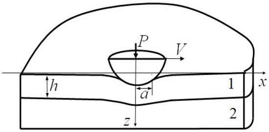
Figure 1.
Scheme of contact between a slider and a two-layered half-space.
The boundary conditions on the surface () are the following:
Here, —the contact pressure, —the circle contact area with radius a, —the friction coefficient, which depends on temperature . The temperature is not constant at the surface because of frictional heating. The contact pressure distribution and the size of the contact area are not known in advance. We assume that the influence of tangential forces on the contact pressure distribution is negligible. Then, the problem becomes axisymmetric.
At the layer–substrate interface (), complete adhesion takes place:
In relations (1) and (2), —stresses and displacements of the elastic layer (i = 1) and substrate (i = 2).
We also use the equilibrium condition
The method for solving the axisymmetric contact problem, taking into account the elastic properties of the coating, substrate, and smooth slider, is described in detail in [12]. It is based on the Hankel integral transforms, the boundary element method (the elements are rings of constant thickness), and an iterative procedure.
After solving the problem, the contact pressure is obtained as a piecewise function (pressure is constant inside each ring element), which is then used to calculate the temperature fields.
Frictional heating of two-layer half-space occurs from the side of a slider (Figure 1). The velocity is small enough so that the problem is a stationary one:
The temperatures in the layer and the substrate satisfy the following boundary conditions. At the surface of the layer (), the heat flux through the contact area is
Here, is the specific power of frictional heat release, determined by the relation:
is the coefficient of separation of heat fluxes at the slider–layer interface, and V—the sliding velocity. The friction coefficient is a known function of temperature. It is assumed that the friction coefficient decreases with increasing temperature. At the layer–substrate interface ():
is the coefficient of thermal conductivity.
Equation (4) with boundary Condition (5)–(7) determine the solution of the heat conduction problem. The distribution of contact pressure required to calculate the heat flux intensity (6) is determined from the solution of the contact problem formulated above.
Let us use the cylindrical coordinate system , the origin of which coincides with the center of the contact area. The heat flux intensity at the boundary is a function of only the radial coordinate . The following dimensionless parameters are used in the problem solution:
Here, ( is maximal contact pressure). Then, (4) is transformed to:
Boundary Condition (5)–(7) can be presented as:
Equation (9) with Condition (10) are solved by applying Hankel integral transforms. Temperature is transformed as follows:
Equation (8) leads to:
The boundary conditions in the space of integral transforms are:
The general solution of Equation (11) can be represented as [9].
Using (13), one can obtain the following expressions for unknown functional coefficients:
Inverse Hankel integral transforms gives a temperature function for the layer and the substrate:
The contact problem solution is obtained using the boundary element method with ring elements. Pressure and heat flux are constant within a ring element. The surface boundary condition for a ring is:
Here, are internal and external radii of a ring j with constant heat flux . For , we have the central circle.
For each ring, we have analytical results of Hankel integral transform, which can be used in (14)–(16):
The inverse Hankel integral transform is calculated numerically. The resulting temperature is obtained with the superposition of solutions for all rings. The temperature distribution is used to initiate an iterative procedure so that the condition is satisfied in the contact area, where the temperature, in turn, depends on the contact pressure. As the first step of the iterations, the maximum value of the friction coefficient corresponding to the starting temperature is used. It should be noted that the iterative procedure converges only if the coefficient of friction decreases with increasing temperature.
3. Results and Discussion
The shape of the axisymmetric smooth slider is determined by the following function:
It is an indenter with flat base and rounded edges. If , Equation (19) defines a shape of a spherical indenter with radius . The cylinder that is considered in further numerical results has a rounding radius of edges according to condition .
Contact and thermal problems solutions depend on the following dimensionless parameters:
The resulting dimensionless functions are analyzed:
Dependence of the friction coefficient on the dimensionless temperature is considered to be a smooth monotonically decreasing function. Such a law should take place for smart coatings that implement the mechanism of self-lubrication during frictional heating. Materials with opposite properties (an increase in the friction force with increasing temperature) are not considered in this study, although there are many such materials. Numerical results were obtained using the following linear dependence:
Below are the results obtained for a flat slider with rounded edges (slider 1) and for a spherical slider (slider 2) in the two main coating test schemes, pin-on-disk and ball-on-disk. In all calculations, it is assumed that the thermal conductivity of the coating is lower than that of the substrate.
Figure 2 shows examples of the contact pressure distribution for slider 1 for the cases of a relatively thin compliant coating (red curve) and a relatively thick one (black curve). Relatively compliant coatings are characterized by . The black curve almost coincides with the half-space solution. In contact with a thinner coating, the pressure under the slider is distributed more evenly. A detailed analysis of the solution of the contact problem for an indenter of this shape and coatings with different properties is given in [12]. The results of solving the thermal problem with an iterative procedure that provides (20) are shown in Figure 3. There is a uniform temperature distribution under the slider (Figure 3b), which, when greater, increases the velocity. In this case, according to (20), shear stresses decrease with an increase in temperature (Figure 3a).
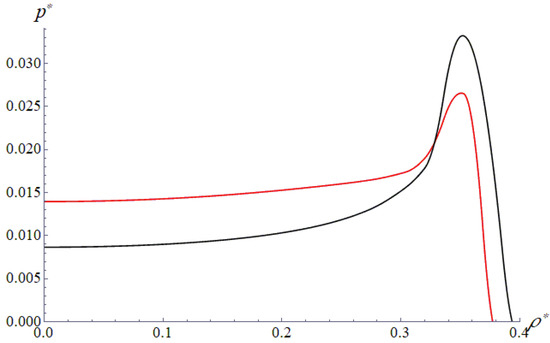
Figure 2.
Slider 1. Contact pressure (red curve) and (black curve). , , , .
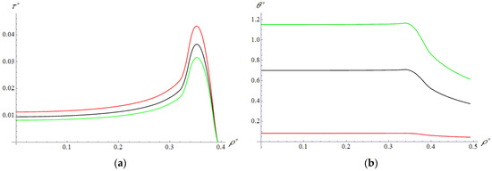
Figure 3.
Slider 1. Distribution of shear stress (a) and temperature (b) on the coating surface. , , , , , , , (red curve), (black curve), (green curve).
One can obtain the resulting force of friction using the integrating function on the contact area. Furthermore, it is presented in dimensionless form:
where is the dimensionless contact area. The value of can be treated as an integral friction coefficient.
An analysis of the effect of sliding velocity on the resulting friction coefficient for three coating thicknesses (Figure 4) allows us to conclude that an increase in velocity leads to a decrease in friction. In this case, the thicker the coating, the more noticeable this effect, which is associated with an increase in the distance between the surface and the more heat-conducting substrate. For a more accurate study of the effect, a curve of dependence of the friction coefficient on the thickness of the coating is obtained at a fixed sliding velocity (Figure 5). After a sharp drop, there is a tendency to a constant, corresponding to the case of half-space with the properties of the coating.
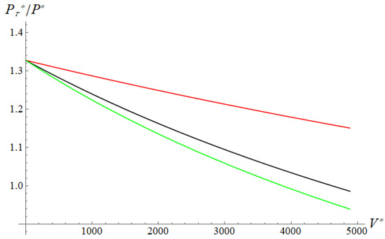
Figure 4.
Slider 1. Resulting friction coefficient dependence on sliding velocity. , , , , , , (red curve), (black curve), (green curve).
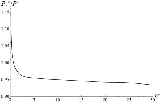
Figure 5.
Slider 1. Resulting friction coefficient dependence on the coating thickness. , , , , , , .
Figure 6, Figure 7, Figure 8, Figure 9, Figure 10 and Figure 11 present the results obtained for the ball slider. For the case of relatively rigid (Figure 6) and relatively compliant (Figure 7) coatings, the maximum temperatures and shear stresses occur in the center of the contact circle. Furthermore, as in the previous case, the higher the velocity, the higher the temperature and the lower the friction force.
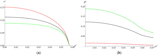
Figure 6.
Slider 2. Distribution of shear stress (a) and temperature (b) on the layer surface. , , , , , , , (red curve), (black curve), (green curve).
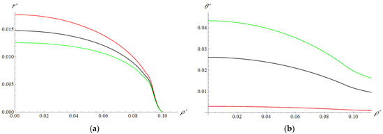
Figure 7.
Slider 2. Distribution of shear stress (a) and temperature (b) on the layer surface. , , , , , , , (red curve), (black curve), (green curve).
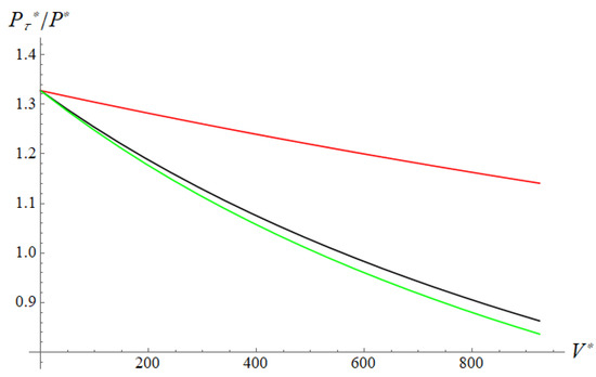
Figure 8.
Slider 2. Resulting friction coefficient dependence on sliding velocity (hard coating). , , , , , , , (red curve), (black curve), (green curve).
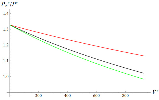
Figure 9.
Slider 2. Resulting friction coefficient dependence on sliding velocity (soft coating). , , , , , , , (red curve), (black curve), (green curve).
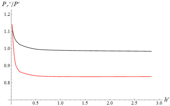
Figure 10.
Slider 2. Resulting friction coefficient dependence on the coating thickness. , , , , . Black curve: , , red curve: , .

Figure 11.
Slider 2. (a) Dependence of the surface shear stress on temperature. Red curve represents linear dependence described by Equation (19), black curve is the nonlinear case. (b) Resulting friction coefficient dependence on sliding velocity. , , , , , , .
Figure 8 and Figure 9 show how the coefficient of friction depends on the velocity at different coating thicknesses. The results are obtained for the analysis of the effect of the coating thickness at a fixed (maximum) velocity (Figure 10). If the coating is relatively rigid, then an increase in its thickness, firstly, leads to a decrease in the contact area and an increase in pressures. Secondly, the substrate, which is more conductive, moves away from the contact. Both of these facts lead to an increase in temperature and a sharp decrease in both the local friction coefficient in the contact area, especially in its center, and the resulting one (red curve in Figure 10). In the case of relatively compliant coatings, an increase in thickness leads to a decrease in contact pressures, which partially levels out the effect of a decrease in thermal conductivity near the contact spot (black curve in Figure 10). With the same thermal conductivity of the coating and the substrate, in the case of rigid coatings, the friction coefficient increases with increasing coating thickness, and in the case of compliant coatings, it decreases.
The above results are obtained for the linear dependence of the local friction coefficient on temperature. This is carried out for the convenience of analysis, and also based on the fact that any experimental dependence can be represented as piecewise linear. At the same time, real materials usually change their frictional properties in a certain temperature range due to structural changes, self-lubrication effect, etc. With a further increase in temperature, these properties stabilize. Such a result is obtained, for example, in [2]. In the dimensionless form, it can be represented as a black curve in Figure 11a. For comparison, the previously used linear function is also shown (red curve). The dependences of the resulting friction coefficient on the velocity for the two variants of are shown in Figure 11b. As expected, the non-linearity of the function leads a rapid drop in the first part of the curve, then the curve becomes flatter than for a linear function.
4. Conclusions
The developed model makes it possible to predict the mutual effect of frictional heating and the friction force that occurs during the dry sliding contact of smart coatings. Smart coatings react to an increase in local temperature by reducing the local coefficient of friction. It is shown that at a low sliding velocity, the ambient temperature is decisive, so the function necessary for calculations can be determined during friction tests in a heat chamber at a low velocity. According to the calculation results, the shear stresses differ more from the Amonton–Coulomb law, increasing the sliding velocity. The ability to reduce shear stresses with increasing temperature is very important, since the strength properties of materials and interfaces often become worse due to heating. Based on the model for known thermal conductivity of the coating material and load-velocity characteristics, it is possible to choose the optimal coating thickness that provides the lowest friction force. When using the model for specific coating materials, the dependences of the friction force on velocity can be used to refine the dependence of the local friction coefficient on temperature.
Author Contributions
Conceptualization, E.T.; methodology, E.T. and F.S.; formal analysis, E.T.; investigation F.S.; data curation, E.T.; writing—original draft preparation, E.T.; writing—review and editing, E.T. and F.S.; visualization, F.S.; supervision, E.T.; project administration, E.T. All authors have read and agreed to the published version of the manuscript.
Funding
This research was funded by the Russian Science Foundation, grant number 22-49-02010.
Institutional Review Board Statement
Not applicable.
Informed Consent Statement
Not applicable.
Data Availability Statement
Not applicable.
Conflicts of Interest
The authors declare no conflict of interest.
Nomenclature
| coordinates in the Cartesian coordinate system; | |
| normal load applied to the slider; | |
| sliding velocity; | |
| layer thickness; | |
| contact area; | |
| radius of the contact area; | |
| friction coefficient in Amonton–Coulomb law; | |
| temperature of the layer () and the substrate (); | |
| normal pressure; | |
| normal and tangential stresses of the layer () and the substrate (); | |
| displacements of the layer () and the substrate (); | |
| specific power of heat release; | |
| coefficient of separation of heat fluxes at the slider-layer interface; | |
| coefficient of thermal conductivity of the layer () and the substrate (); | |
| coordinates in the cylindrical coordinate system; | |
| dimensionless coordinates in the cylindrical coordinate system; | |
| dimensionless temperature of the layer () and the substrate (); | |
| dimensionless layer thickness; | |
| relation of the substrate and the layer coefficients of thermal conductivity; | |
| dimensionless specific power of heat release; | |
| Hankel integral transformation of the dimensionless temperature of the layer () and the substrate (); | |
| coordinate in the Hankel integral transform space; | |
| Bessel functions of the first kind; | |
| function defining the slider shape; | |
| radius of flat surface of the slider | |
| curvature radius of rounded edges of the slider; | |
| radius of the spherical slider; | |
| Young′s modulus of the layer () and the substrate (); | |
| Poisson ratio of the layer () and the substrate (); | |
| relation of Young′s modulus of the layer () and the substrate (); | |
| dimensionless layer thickness; | |
| dimensionless normal load applied to the slider; | |
| dimensionless tangential force by friction; | |
| relation of the substrate and the layer coefficients of thermal conductivity; | |
| dimensionless normal pressure; | |
| dimensionless tangential stress; | |
| dimensionless sliding velocity; | |
| dimensionless temperature; | |
| dimensionless coordinates in the cylindrical coordinate system. |
References
- Wang, R.; Li, W.; Ji, B.; Fang, D. Fracture strength of the particulate-reinforced ultra-high temperature ceramics based on a temperature dependent fracture toughness model. J. Mech. Phys. Solids 2017, 107, 365–378. [Google Scholar] [CrossRef]
- Moghaddam, P.V.; Prakash, B.; Vuorinen, E.; Fallqvist, M.; Andersson, J.M.; Hardell, J. High temperature tribology of TiAlN PVD coating sliding against 316L stainless steel and carbide-free bainitic steel. Tribol. Int. 2020, 159, 106847. [Google Scholar] [CrossRef]
- Fox-Rabinovich, G.; Veldhuis, S.C.; Kovalev, A.; Wainstein, D.; Gershman, I.; Korshunov, S.; Shuster, L.; Endrino, J. Features of self-organization in ion modified nanocrystalline plasma vapor deposited AlTiN coatings under severe tribological conditions. J. Appl. Phys. 2007, 102, 74305. [Google Scholar] [CrossRef]
- Karsloy, G.; Eger, D. Heat Conductivity of Solids; Nauka: Moscow, Russia, 1964. [Google Scholar]
- Barber, J. The conduction of heat from sliding solids. Int. J. Heat Mass Transf. 1970, 13, 857–869. [Google Scholar] [CrossRef]
- Liu, Y.; Barber, J.R. Transient heat conduction between rough sliding surfaces. Tribol. Lett. 2014, 55, 23–33. [Google Scholar] [CrossRef]
- Smith, E.H.; Arnell, R.D. The prediction of frictional temperature increases in dry, sliding contacts between different materials. Tribol. Lett. 2014, 55, 315–328. [Google Scholar] [CrossRef]
- Tian, X.; Kennedy, F.E. Temperature Rise at the Sliding Contact Interface for a Coated Semi-Infinite Body. J. Tribol. 1993, 115, 1–9. [Google Scholar] [CrossRef]
- Evtushenko, A.A.; Ivanik, E.G.; Evtushenko, E.A. Approximate method for determining the maximum temperature during quasistationary heating of a piecewise-homogeneous half-space. J. Appl. Mech. Tech. Phys. 2005, 46, 375–385. [Google Scholar] [CrossRef]
- Makhovskaya, Y.Y. Modeling of Stationary Frictional Heating of a Coated Body. J. Frict. Wear 2019, 40, 258–265. [Google Scholar] [CrossRef]
- Białas, M.; Maciejewski, J.; Kucharski, S. Friction coefficient of solid lubricating coating as a function of contact pressure: Experimental results and microscale modeling. Contin. Mech. Thermodyn. 2021, 33, 1733–1745. [Google Scholar] [CrossRef]
- Torskaya, E.; Goryacheva, I. The effect of interface imperfection and external loading on the axisymmetric contact with a coated solid. Wear 2003, 254, 538–545. [Google Scholar] [CrossRef]
Publisher’s Note: MDPI stays neutral with regard to jurisdictional claims in published maps and institutional affiliations. |
© 2022 by the authors. Licensee MDPI, Basel, Switzerland. This article is an open access article distributed under the terms and conditions of the Creative Commons Attribution (CC BY) license (https://creativecommons.org/licenses/by/4.0/).