Non-Newtonian Thermo-Elastohydrodynamics and Sub-Surface Stress Field of High-Performance Racing Spur Gears

 , ,
, ,  , and
, and 
Abstract
:1. Introduction
2. Methodology
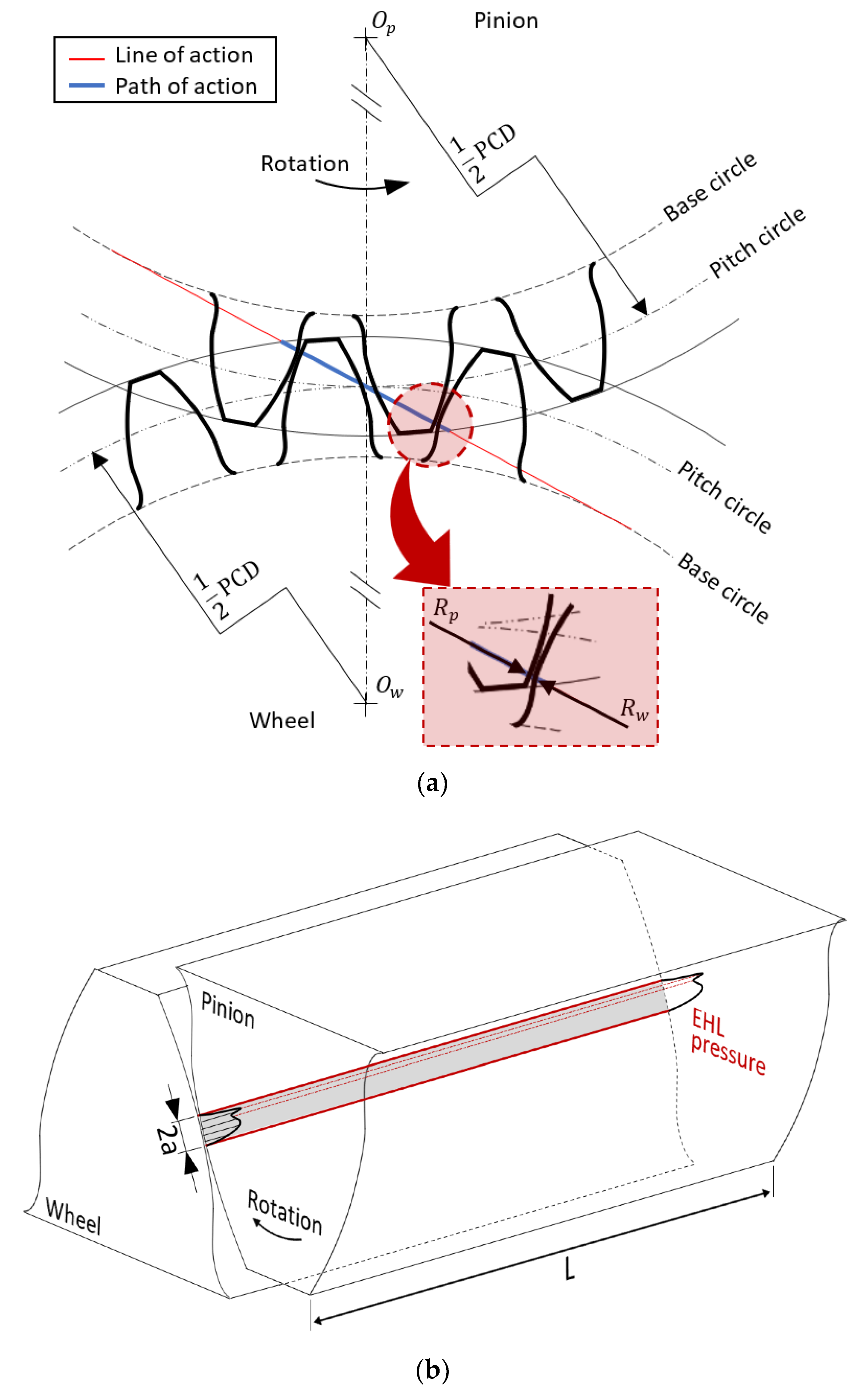
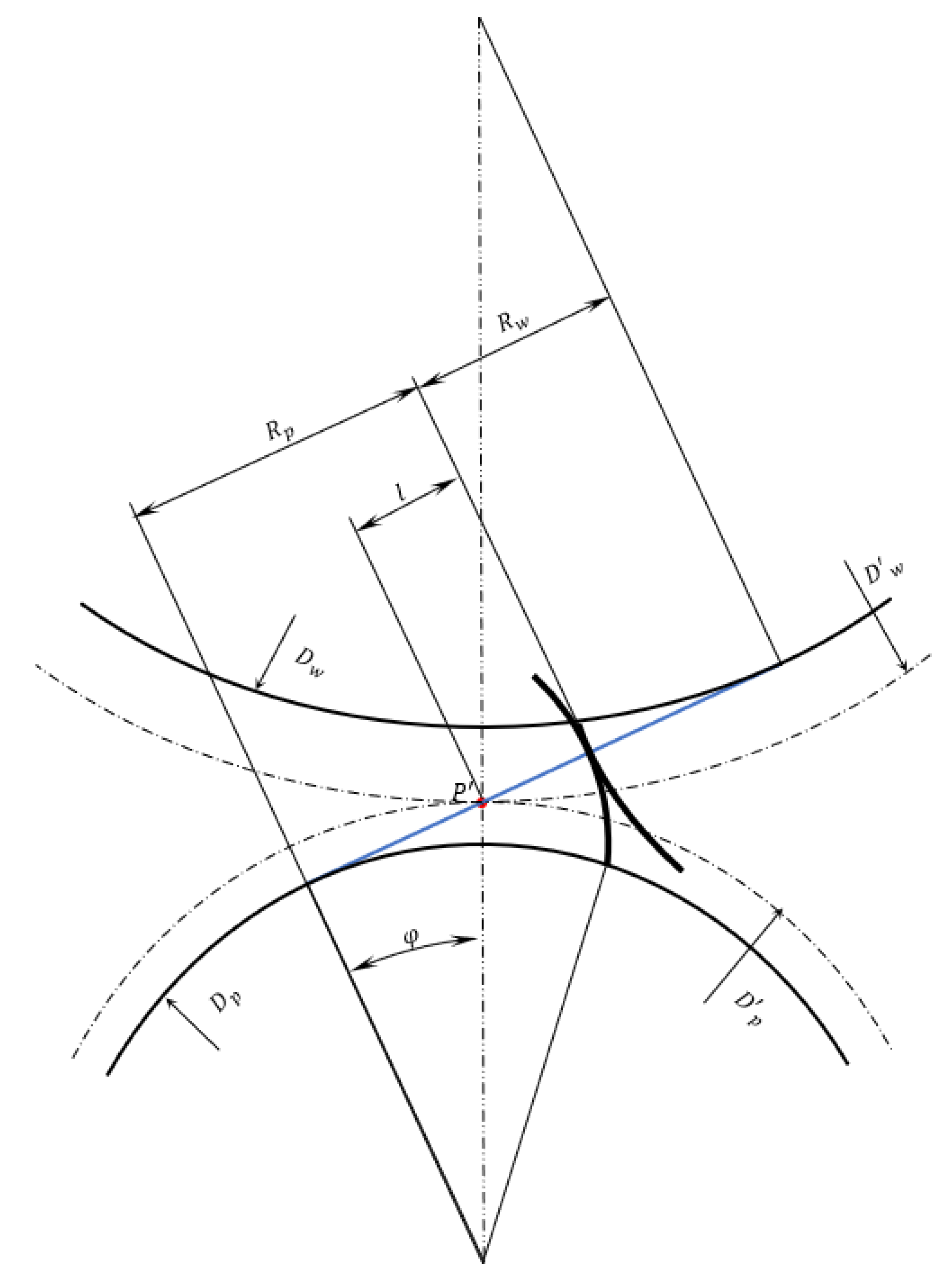
2.1. Lubricated Loaded Tooth Contact Analysis (LLTCA)
2.2. Elastohydrodynamic Lubrication (EHL)
2.3. Method of Solution
- Parameters from LLTCA are input at the start of a meshing cycle;
- An initial guess is made for the lubricant film thickness at the centre of the contact;
- The computational domain is set with an inlet length of and contact exit position of where is the contact semi-half-width (Equation (4)). The number of elements used in the direction of lubricant entrainment, x, is 2051;
- Iterative pressure residuals are found using EIN iterations and the pressures are updated using the recursive expression:where n denotes the iteration step and is the under-relaxation factor, typically: -;
- The pressure convergence criterion used is:
- The lubricant reaction is obtained as:
- The instantaneous equilibrium condition is sought using the load convergence criterion:
- If the stated equilibrium condition is not satisfied, the film thickness is updated through the modification of the undeformed gap as:where is the damping (load relaxation) factor. In the current analysis, the value of is used. Subsequently, density and viscosity are updated using the converged pressures. Then, steps 4 to 8 are repeated until step 7 is satisfied;
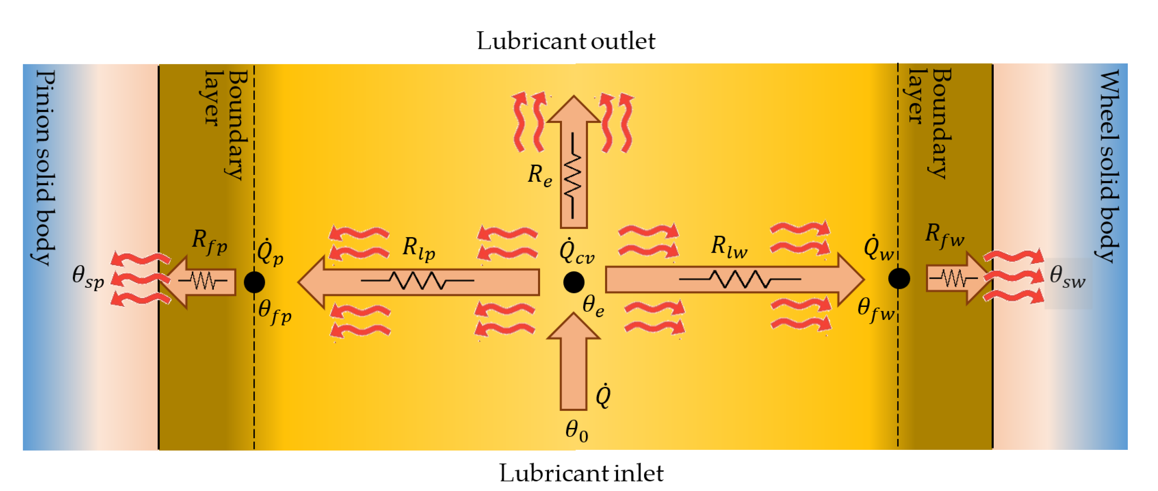
- Once the film thickness is determined, the thermal network model is used to obtain the temperature of the lubricant as well as the flash temperatures of the contacting surfaces;
- The lubricant temperature is used to adjust the lubricant density and dynamic viscosity.
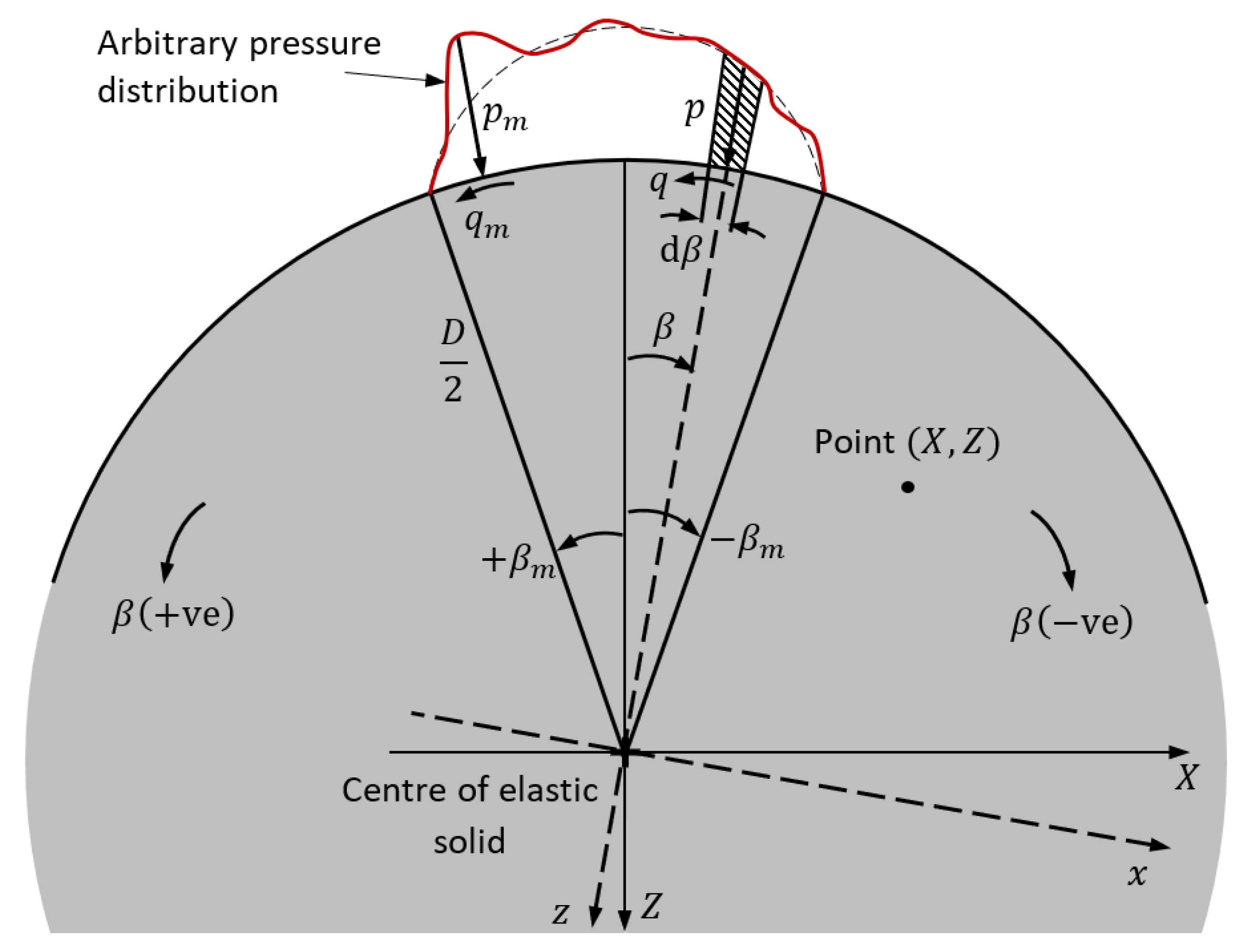
2.4. Sub-Surface Stress Field
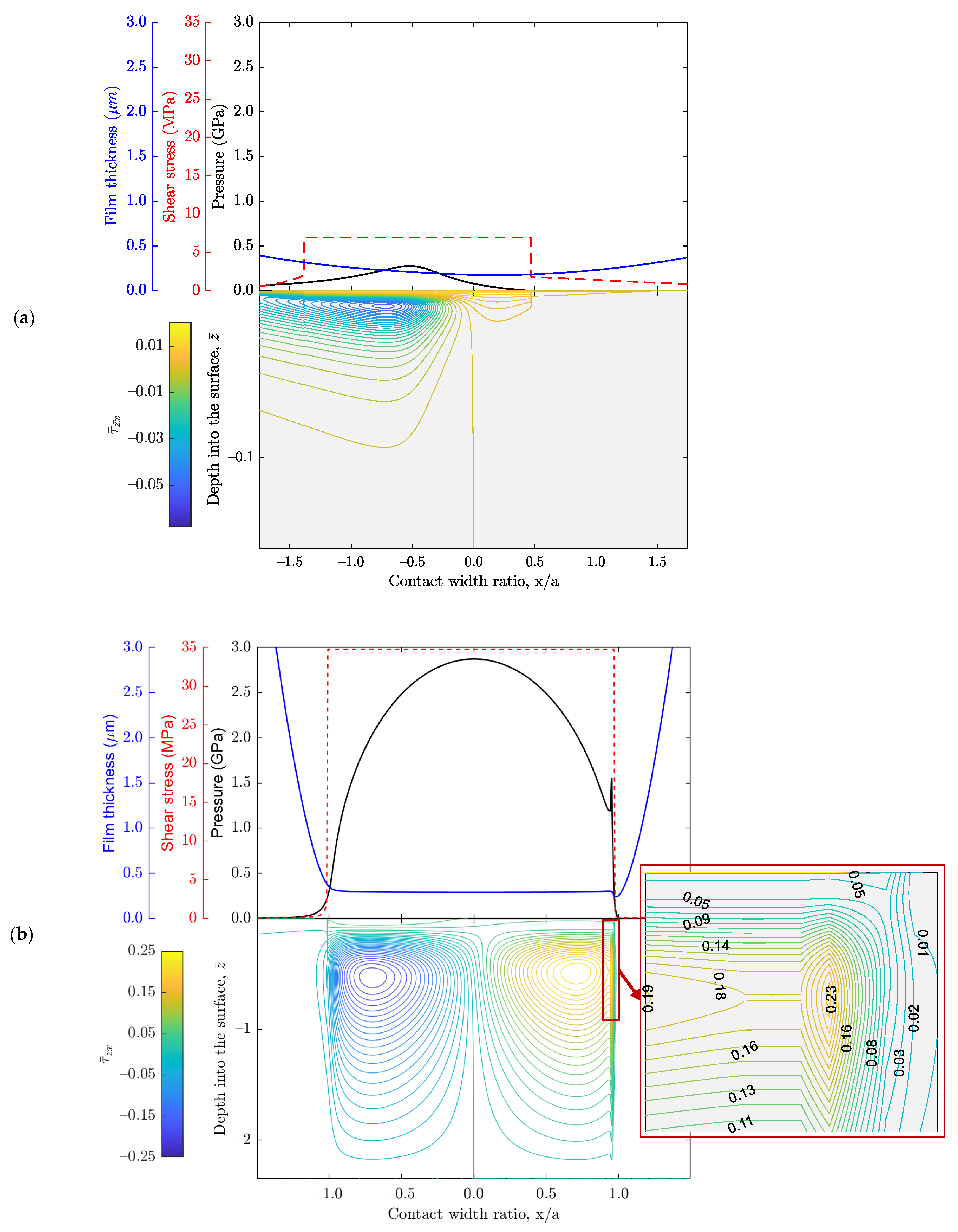
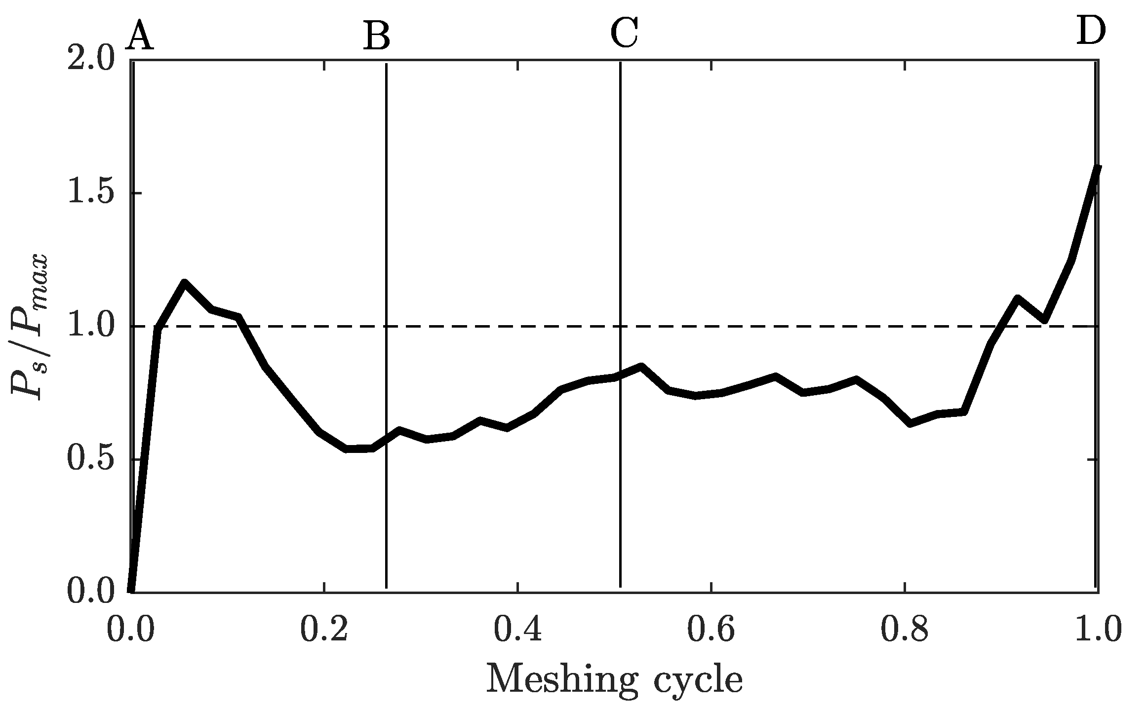
3. Results and Discussion
4. Concluding Remarks
Author Contributions
Funding
Institutional Review Board Statement
Informed Consent Statement
Data Availability Statement
Conflicts of Interest
Nomenclature
| Roman symbols | |
| area of contact | |
| footprint semi-half-width | |
| specific heat capacity of the gear material | |
| specific heat capacity of the lubricant | |
| diameter of the equivalent contacting elastic solid | |
| pitch diameter of the pinion gear | |
| pitch diameter of the wheel gear | |
| Young’s modulus of elasticity | |
| effective Young’s modulus of elasticity of the contacting pair | |
| a non-Newtonian viscosity function | |
| friction | |
| lubricant film thickness | |
| the minimum film thickness (rigid clearance) | |
| the central contact lubricant film thickness obtained from EHL analysis | |
| heat transfer coefficient | |
| thermal conductivity of the lubricant | |
| thermal conductivity of the gear material | |
| length of the rectangular contact strip (footprint) | |
| distance of contact point from pitch point along the line of contact | |
| mass flow rate of lubricant | |
| lubricant pressure | |
| maximum contact pressure | |
| the average (Pascal) contact pressure | |
| rate of heat generation through contact friction | |
| proportion of generated heat conducted away through pinion surface | |
| proportion of generated heat conducted away through wheel surface | |
| convective heat transfer through lubricant flow | |
| the reduced radius of a meshing pair | |
| the equivalent thermal resistance for lubricant mass flow rate | |
| thermal resistance due to the surface flash temperature rise | |
| thermal resistance due to lubricant film | |
| radius of curvature of pinion tooth profile at the point of contact | |
| resistance to heat flow through contacting surfaces | |
| radius of curvature of wheel tooth at the point of contact | |
| the geometric profile of the equivalent ellipsoidal elastic solid | |
| time | |
| speed of lubricant entrainment into the contact | |
| instantaneous surface velocity of the pinion tooth | |
| instantaneous surface velocity of the wheel tooth | |
| velocity of side-leakage flow | |
| contact load | |
| lubricant reaction | |
| surface co-ordinates | |
| X,Z | sub-surface genera co-ordinates |
| Greek symbols | |
| mean pressure piezo-viscosity of the lubricant | |
| pressure–viscosity coefficient | |
| location within the arc of contact | |
| lubricant shear rate | |
| localised elastic deflection | |
| dynamic viscosity of lubricant | |
| ambient dynamic viscosity of the lubricant at the reference temperature | |
| effective dynamic viscosity of lubricant including non-Newtonian behaviour | |
| bulk inlet temperature of lubricant | |
| effective lubricant contact temperature | |
| assumed initial surface temperature | |
| solid body temperature | |
| Stribeck film ratio | |
| coefficient of friction | |
| Poisson’s ratio | |
| density of lubricant | |
| density of lubricant at ambient temperature and pressure | |
| density of the gear material | |
| Composite surface roughness | |
| sub-surface normal stress in | |
| sub-surface normal stress in direction of the surface coordinate system | |
| sub-surface normal stress in direction of the sub-surface coordinate system | |
| sub-surface normal stress in direction of the surface coordinate system | |
| characteristic shear stress of the lubricant | |
| sub-surface shear stress in plane | |
| sub-surface shear stress in plane | |
| progressive pinion angle | |
| angular velocity of the pinion gear | |
| angular velocity of the wheel gear | |
| Abbreviations | |
| CMM | Coordinate measuring machine |
| EHD | Elastohydrodynamic |
| EHL | Elastohydrodynamic lubrication |
| LLTCA | Lubricated loaded tooth contact analysis |
| NVH | Noise, vibration and harshness |
| TCA | Tooth contact analysis |
| TEHL | Thermo-elastohydrodynamic lubrication |
Appendix A
References
- Li, S.; Kahraman, A. Prediction of spur gear mechanical power losses using a transient elastohydrodynamic lubrication model. Tribol. Trans. 2010, 53, 554–563. [Google Scholar]
- Li, S.; Kahraman, A. A tribo-dynamic model of a spur gear pair. J. Sound Vib. 2013, 332, 4963–4978. [Google Scholar]
- Mohammadpour, M.; Theodossiades, S.; Rahnejat, H.; Kelly, P. Transmission efficiency and noise, vibration and harshness refinement of differential hypoid gear pairs. Proc. Inst. Mech. Eng. Part K J. Multi-Body Dyn. 2014, 228, 19–33. [Google Scholar]
- Mehdigoli, H.; Rahnejat, H.; Gohar, R. Vibration response of wavy surfaced disc in elastohydrodynamic rolling contact. Wear 1990, 139, 1–5. [Google Scholar]
- Dareing, D.W.; Johnson, K.L. Fluid film damping of rolling contact vibrations. J. Mech. Eng. Sci. 1975, 17, 214–218. [Google Scholar]
- Simon, V. Optimal tooth modifications for spur and helical gears. J. Mech. Trans. Autom. 1989, 111, 611–615. [Google Scholar]
- Velex, P.; Maatar, M. A mathematical model for analyzing the influence of shape deviations and mounting errors on gear dynamic behaviour. J. Sound Vib. 1996, 191, 629–660. [Google Scholar]
- Kahraman, A.; Blankenship, G.W. Effect of involute tip relief on dynamic response of spur gear pair. J. Mech. Des. 1999, 121, 313–315. [Google Scholar]
- Elisaus, V.; Mohammadpour, M.; Theodossiades, S.; Rahnejat, H. Effect of teeth micro-geometrical form modification on contact kinematics and efficiency of high performance transmissions. Proc. Inst. Mech. Eng. Part K J. Multi-Body Dyn. 2017, 231, 538–555. [Google Scholar]
- Fatourehchi, E.; Mohammadpour, M.; King, P.D.; Rahnejat, H.; Trimmer, G.; Williams, A. Microgeometrical tooth profile modification influencing efficiency of planetary hub gears. Int. J. Powertrains 2018, 7, 162–179. [Google Scholar]
- Fatourehchi, E.; Mohammadpour, M.; King, P.D.; Rahnejat, H.; Trimmer, G. Effect of tooth profile modification on the durability of planetary hub gears. Int. J. Powertrains 2019, 8, 40–57. [Google Scholar]
- Wu, S.; Cheng, H.S. A friction model of partial-EHL contacts and its application to power loss in spur gears. Tribol. Trans. 1991, 34, 398–407. [Google Scholar]
- Li, S.; Kahraman, A. A transient mixed elastohydrodynamic lubrication model for spur gear pairs. J. Tribol. 2010, 132, 011501. [Google Scholar]
- Gohar, R.; Rahnejat, H. Fundamentals of Tribology, 3rd ed.; World Scientific: London, UK, 2018. [Google Scholar]
- Olver, A.V. Gear lubrication—A review. Proc. Inst. Mech. Eng. Part J J. Eng. Tribol. 2002, 216, 255–267. [Google Scholar]
- Masjedi, M.; Khonsari, M.M. On the prediction of steady-state wear rate in spur gears. Wear 2015, 342, 234–243. [Google Scholar]
- Liu, H.; Zhu, C.; Sun, Z.; Song, C. Starved lubrication of a spur gear pair. Tribol. Int. 2016, 94, 52–60. [Google Scholar]
- Li, S.; Kolivand, A.; Anisetti, A. An Investigation on Starvation Onset of Rough Surface Line Contacts. J. Tribol. 2021, 144, 031602. [Google Scholar]
- Lorenz, S.J.; Sadeghi, F.; Trivedi, H.K.; Rosado, L.; Kirsch, M.S.; Wang, C. An approach for predicting failure mechanism in rough surface rolling contact fatigue. Tribol. Int. 2021, 158, 106923. [Google Scholar]
- Sadeghi, F. Elastohydrodynamic lubrication. In Tribology and Dynamics of Engine and Powertrain; Woodhead Publishing: Cambridge, UK, 2010; pp. 171–226. [Google Scholar]
- Beghini, E.R.; Dwyer-Joyce, R.S.; Ioannides, E.; Jacobson, B. Elastic/plastic contact and endurance life prediction. J. Phys. D Appl. Phys. 1992, 25, 379. [Google Scholar]
- Ding, Y.; Rieger, N.F. Spalling formation mechanism for gears. Wear 2003, 254, 1307–1317. [Google Scholar]
- Tao, J.; Hughes, T.G.; Evans, H.P.; Snidle, R.W.; Hopkinson, N.A.; Talks, M.; Starbuck, J.M. Elastohydrodynamic lubrication analysis of gear tooth surfaces from micropitting tests. J. Tribol. 2003, 125, 267–274. [Google Scholar]
- Ioannides, E.; Harris, T.A. A new fatigue life model for rolling bearings. J. Tribol. 1985, 197, 367–378. [Google Scholar]
- Huber, M.T.; Fuchs, S. Spannungverleitung bei der beruhrung zweier elastischer zylinder. Phys. Zeitschr. 1914, 15, 298–303. [Google Scholar]
- Lyman, J. Reversing normal strains produced by rolling contact load. J. Lub. Tech. 1967, 89, 76–80. [Google Scholar]
- Poritsky, H. Stresses and deflections of cylindrical bodies in contact with application to contact of gears and locomotive wheels. J. Appl. Mech. 1950, 18, 191–201. [Google Scholar]
- Johnson, K.L. One hundred years of Hertz contact. Proc. Inst. Mech. Eng. 1982, 196, 363–378. [Google Scholar]
- Johnson, K.L. Contact Mechanics; Cambridge University Press: Cambridge, UK, 1987. [Google Scholar]
- Johns-Rahnejat, P.M.; Gohar, R. Point contact elastohydrodynamic pressure distribution and sub-surface stress field. In Proceedings of the Tri-Annual Conference on Multi-Body Dynamics: Monitoring and Simulation Techniques, Bradford, UK, March 1997; pp. 161–179. [Google Scholar]
- Houpert, L.D.; Ioannides, E.; Kuypers, J.C.; Tripp, J. The effect of the EHD pressure spike on rolling bearing fatigue. J. Tribol. 1987, 109, 444–450. [Google Scholar]
- Teodorescu, M.; Kushwaha, M.; Rahnejat, H.; Rothberg, S.J. Multi-physics analysis of valve train systems: From system level to microscale interactions. Proc. Inst. Mech. Eng. Part K J. Multi-Body Dyn. 2007, 221, 349–361. [Google Scholar]
- Johns-Rahnejat, P.M. Pressure and Stress Distribution Under Elastohydrodynamic Point Contacts. Ph.D. Thesis, Imperial College of Science and Technology, University of London, London, UK, 1988. [Google Scholar]
- Johns-Rahnejat, P.M.; Dolatabadi, N.; Rahnejat, H. Analytical elastostatic contact mechanics of highly-loaded contacts of varying conformity. Lubricants 2020, 8, 89. [Google Scholar]
- Oglieve, C.; Sivayogan, G.; Mohammadpour, M.; Rahnejat, H. Lubricated loaded tooth contact analysis for spur gear pair. Int. J. Powertrains 2019, 8, 23–39. [Google Scholar]
- Litvin, F.L.; Fuentes, A. Gear Geometry and Applied Theory; Cambridge University Press (CUP): Cambridge, UK, 2004. [Google Scholar]
- Vijayakar, S.M. Tooth Contact Analysis Software: CALYX; Advanced Numerucal Solutions: Hilliard, OH, USA, 1998. [Google Scholar]
- Karagiannis, I.; Theodossiades, S.; Rahnejat, H. On the dynamics of lubricated hypoid gears. Mech. Mach. Theory 2012, 48, 94–120. [Google Scholar]
- Sivayogan, G.; Rahmani, R.; Rahnejat, H. Lubricated loaded tooth contact analysis and non-Newtonian thermoelastohydrodynamics of high-performance spur gear transmission systems. Lubricants 2020, 8, 20. [Google Scholar]
- Merritt, H.E. Gear Engineering; John Wiley & Sons: New York, NY, USA, 1972. [Google Scholar]
- Evans, C.R.; Johnson, K.L. Regimes of traction in elastohydrodynamic lubrication. Proc. Inst. Mech. Eng. Part C J. Mech. Eng. Sci. 1986, 200, 313–324. [Google Scholar]
- Mohammadpour, M.; Theodossiades, S.; Rahnejat, H.; Dowson, D. Non-Newtonian mixed thermo-elastohydrodynamics of hypoid gear pairs. Proc. Inst. Mech. Eng. Part J J. Eng. Tribol. 2018, 232, 1105–1125. [Google Scholar]
- De la Cruz, M.; Theodossiades, S.; King, P.; Rahnejat, H. Transmission drive rattle with thermo-elastohydrodynamic impacts: Numerical and experimental investigations. Int. J. Powertrains 2011, 1, 137–161. [Google Scholar]
- Sivayogan, G.; Rahmani, R.; Rahnejat, H. Transient analysis of isothermal elastohydrodynamic point contacts under complex kinematics of combined rolling, spinning and normal approach. Lubricants 2020, 8, 81. [Google Scholar]
- Houpert, L. New results of traction force calculations in elastohydrodynamic contacts. Trans. ASME J. Tribol. 1985, 107, 241–245. [Google Scholar]
- Vogel, H. The temperature dependence law of the viscosity of fluids. Phys. Z. 1921, 22, 645–646. [Google Scholar]
- Paouris, L.; Rahmani, R.; Theodossiades, S.; Rahnejat, H.; Hunt, G.; Barton, W. An analytical approach for prediction of elastohydrodynamic friction with inlet shear heating and starvation. Tribol. Lett. 2016, 64, 10. [Google Scholar]
- Wang, Y.Q.; Yi, X.J. Non-Newtonian transient thermoelastohydrodynamic lubrication analysis of an involute spur gear. Lubr. Sci. 2010, 22, 465–478. [Google Scholar]
- Xiao, Z.; Li, Z.; Shi, X.; Zhou, C. Oil film damping analysis in non-Newtonian transient thermal elastohydrodynamic lubrication for gear transmission. J. Appl. Mech. 2018, 85, 035001. [Google Scholar]
- Khonsari, M.M.; Hua, D.Y. Generalized non-Newtonian elastohydrodynamic lubrication. Tribol. Int. 1993, 26, 405–411. [Google Scholar]
- Havriliak, S.; Negami, S. A complex plane representation of dielectric and mechanical relaxation processes in some polymers. Polymer 1967, 8, 161–210. [Google Scholar]
- Dowson, D.; Higginson, G.R. A numerical solution to the elasto-hydrodynamic problem. J. Mech. Eng. Sci. 1959, 1, 6–15. [Google Scholar]
- Kumar, P.; Khonsari, M.M. Combined effects of shear thinning and viscous heating on EHL characteristics of rolling/sliding line contacts. J. Tribol. 2008, 130, 041505. [Google Scholar]
- Zhao, J.; Sheng, W.; Li, Z.; Zhang, H.; Zhu, R. Study on the Lubrication Characteristics of Spur Gear Pairs with Low Sliding Ratio under Mixed Elastohydrodynamic Lubrication. J. Tribol. 2022, 144, 071604. [Google Scholar]
- Morris, N.; Rahmani, R.; Rahnejat, H.; King, P.D.; Fitzsimons, B. Tribology of piston compression ring conjunction under transient thermal mixed regime of lubrication. Tribol. Int. 2013, 59, 248–258. [Google Scholar]
- Olver, A.V.; Spikes, H.A. Prediction of traction in elastohydrodynamic lubrication. Proc. Inst. Mech. Eng. Part J J. Eng. Trib. 1998, 212, 321–332. [Google Scholar]
- Gohar, R.; Safa, M.M.A. Fluid film lubrication. In Tribology and Dynamics of Engine and Powertrain; Woodhead Publishing: Cambridge, UK, 2010; pp. 132–170. [Google Scholar]
- Paouris, L.; Rahmani, R.; Theodossiades, S.; Rahnejat, H.; Hunt, G.; Barton, W. Inefficiency predictions in a hypoid gear pair through tribodynamics analysis. Tribol. Int. 2018, 119, 631–644. [Google Scholar]
- Dowson, D. Elastohydrodynamic and micro-elastohydrodynamic lubrication. Wear 1995, 190, 125–138. [Google Scholar]
- Jalali-Vahid, D.; Rahnejat, H.; Gohar, R.; Jin, Z.M. Prediction of oil-film thickness and shape in elliptical point contacts under combined rolling and sliding motion. Proc. Inst. Mech. Eng. Part J J. Eng. Tribol. 2000, 214, 427–437. [Google Scholar]
- Johns-Rahnejat, P.M.; Karami, G.; Aini, R.; Rahnejat, H. Fundamentals and Advances in Elastohydrodynamics: The Role of Ramsey Gohar. Lubricants 2021, 9, 120. [Google Scholar]
- Teodorescu, M.; Votsios, V.; Rahnejat, H. Fundamentals of impact dynamics of semi-infinite and layered solids. In Tribology and Dynamics of Engine and Powertrain; Woodhead Publishing: Cambridge, UK, 2010; pp. 105–132. [Google Scholar]
- Love, A.E.H. The stress produced in a semi-infinite solid by pressure on part of the boundary. Phil. Trans. Royal Soc. Lond. A 1929, 228, 377–420. [Google Scholar]
- Muskhelishvili, N.I. Some Basic Problems of the Mathematical Theory of Elasticity; Noordhoff: Groningen, The Netherlands, 1963; p. 17404. [Google Scholar]
- Jacobson, B.O. High pressure-short time shear strength analyzer for lubricants. J. Tribol. 1985, 107, 220–223. [Google Scholar]
- Masjedi, M.; Khonsari, M.M. Theoretical and experimental investigation of traction coefficient in line-contact EHL of rough surfaces. Tribol. Int. 2014, 70, 179–189. [Google Scholar]
- Greenwood, J.A. Presentation of Elastohydrodynamic Film-Thickness Results. J. Mech. Eng. Sci. 1969, 11, 128–132. [Google Scholar]
- Johns-Rahnejat, P.M.; Gohar, R. Measuring contact pressure distributions under elastohydrodynamic point contacts. Tribotest 1994, 1, 33–53. [Google Scholar]
- Hamrock, B.J.; Dowson, D. Isothermal elastohydrodynamic lubrication of point contacts: Part IV—Starvation results. J. Lubr. Tech. 1977, 99, 15–23. [Google Scholar]
- Safa, M.M.A.; Gohar, R. Pressure distribution under a ball impacting a thin lubricant layer. J. Tribol. 1986, 108, 372–376. [Google Scholar]
- Al-Samieh, M.F.; Rahnejat, H. Physics of lubricated impact of a sphere on a plate in a narrow continuum to gaps of molecular dimensions. J. Phys. D Appl. Phys. 2002, 35, 2311. [Google Scholar]
- Tipei, N. Boundary conditions of a viscous flow between surfaces with rolling and sliding motion. J. Lubr. Tech. 1968, 90, 254–261. [Google Scholar]
- Birkhoff, G.; Hays, D.F. Free boundaries in partial lubrication. J. Math. Phys. 1963, 42, 126–138. [Google Scholar]
- Fatourehchi, E.; Shahmohamadi, H.; Mohammadpour, M.; Rahmani, R.; Theodossiades, S.; Rahnejat, H. Thermal analysis of an oil jet-dry sump transmission gear under mixed-elastohydrodynamic conditions. J. Tribol. 2018, 140, 051502. [Google Scholar]
- Liu, H.; Liu, H.; Zhu, C.; Wei, P.; Tang, J. Tribological behavior of coated spur gear pairs with tooth surface roughness. Friction 2019, 7, 117–128. [Google Scholar]
- Zhou, Y.; Zhu, C.; Liu, H.; Song, C.; Li, Z. A numerical study on the contact fatigue life of a coated gear pair under EHL. Ind. Lubr. Tribol. 2018, 70, 23–32. [Google Scholar]
- Liu, H.; Liu, H.; Zhu, C.; He, H.; Wei, P. Evaluation of contact fatigue life of a wind turbine gear pair considering residual stress. J. Tribol. 2018, 140, 041102. [Google Scholar]


| Parameter | Value | Unit |
|---|---|---|
| Modulus of elasticity of gear material, | 206 | GPa |
| Poison ratio of solid, | 0.3 | - |
| Density of the solid, | 7800 | kg/m3 |
| Thermal conductivity of solid, | 46.7 | W/m·K |
| Specific heat capacity of the solid, | 470 | J/kg·K |
| Dynamic viscosity of lubricant at 40 °C, | 0.03034 | Pa.s |
| Pressure–viscosity coefficient at 40 °C, | 1.67 × 10⁻⁸ | 1/Pa |
| Thermal conductivity of lubricant, | 0.137 | W/m·K |
| Specific heat capacity of lubricant, | 1670 | J/kg·K |
| Characteristic shear stress, | 2 | MPa |
| Havriliak–Negami non-Newtonian model parameters: | ||
| 0.7 | - | |
| 1 | - | |
| 7.9 × 10⁻⁸ | s |
| Location, Grid Point | Input Parameters | Output Parameters | ||||
|---|---|---|---|---|---|---|
| Sliding Velocity (m/s) | Contact Temperature (°C) | Equivalent Radius of Curvature (mm) | Max. Shear Stress (MPa) | Max. Pressure (Gpa) | EHL Pressure Spike (Gpa) | |
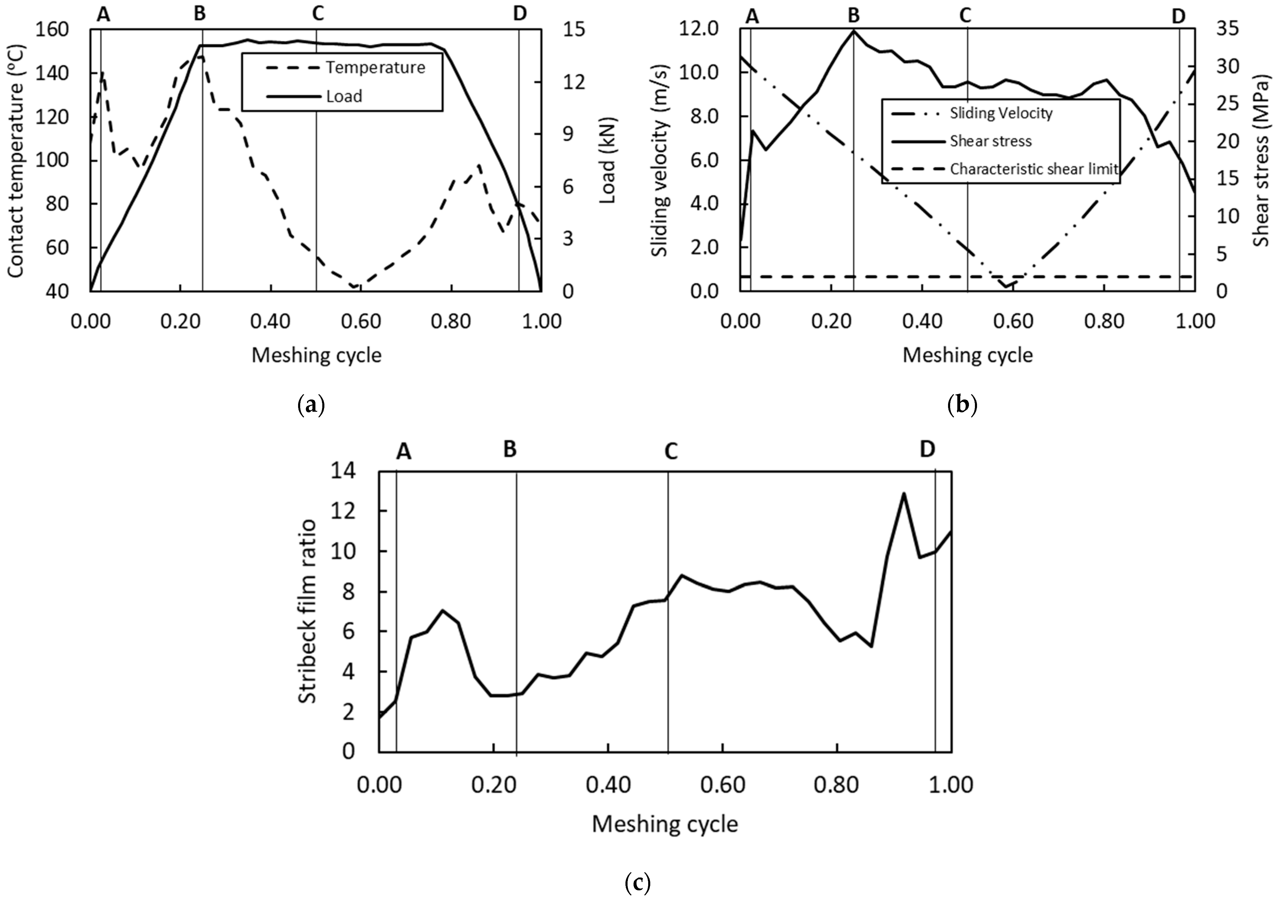
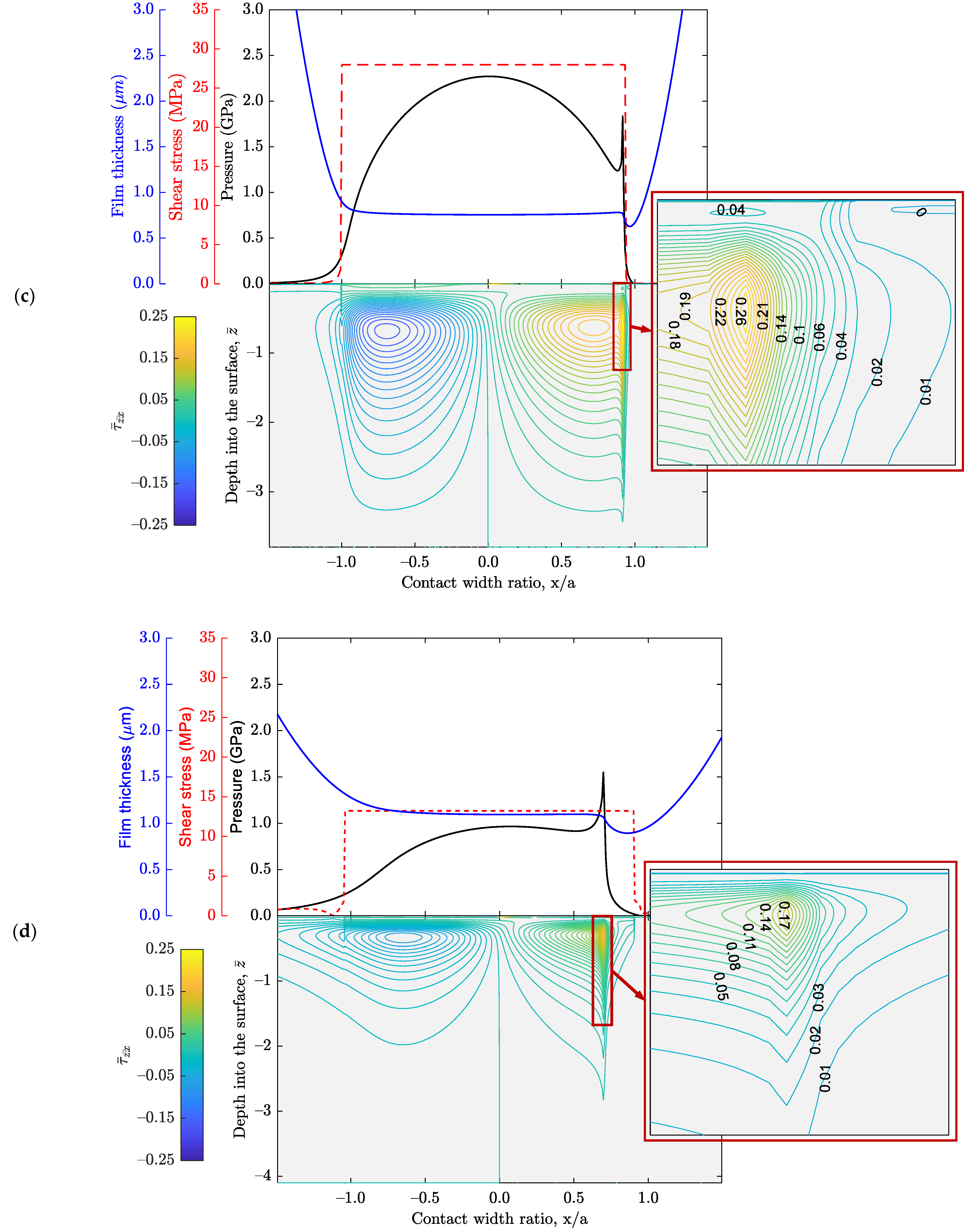
| A: Initial approach | 10.699 | 107.8 | 0.608 | 6.94 | 0.277 | -- |
| B: Max. Hertz pressure | 6.329 | 147.4 | 4.713 | 34.77 | 2.872 | 1.556 |
| C: Pitch point | 1.896 | 56.4 | 7.599 | 27.98 | 2.271 | 1.834 |
| D: Onset of separation | 10.093 | 70.0 | 8.156 | 13.22 | 1.550 | 1.550 |
Publisher’s Note: MDPI stays neutral with regard to jurisdictional claims in published maps and institutional affiliations. |
© 2022 by the authors. Licensee MDPI, Basel, Switzerland. This article is an open access article distributed under the terms and conditions of the Creative Commons Attribution (CC BY) license (https://creativecommons.org/licenses/by/4.0/).
Share and Cite
Sivayogan, G.; Dolatabadi, N.; Johns-Rahnejat, P.; Rahmani, R.; Rahnejat, H. Non-Newtonian Thermo-Elastohydrodynamics and Sub-Surface Stress Field of High-Performance Racing Spur Gears. Lubricants 2022, 10, 146. https://doi.org/10.3390/lubricants10070146
Sivayogan G, Dolatabadi N, Johns-Rahnejat P, Rahmani R, Rahnejat H. Non-Newtonian Thermo-Elastohydrodynamics and Sub-Surface Stress Field of High-Performance Racing Spur Gears. Lubricants. 2022; 10(7):146. https://doi.org/10.3390/lubricants10070146
Chicago/Turabian StyleSivayogan, Gajarajan, Nader Dolatabadi, Patricia Johns-Rahnejat, Ramin Rahmani, and Homer Rahnejat. 2022. "Non-Newtonian Thermo-Elastohydrodynamics and Sub-Surface Stress Field of High-Performance Racing Spur Gears" Lubricants 10, no. 7: 146. https://doi.org/10.3390/lubricants10070146
APA StyleSivayogan, G., Dolatabadi, N., Johns-Rahnejat, P., Rahmani, R., & Rahnejat, H. (2022). Non-Newtonian Thermo-Elastohydrodynamics and Sub-Surface Stress Field of High-Performance Racing Spur Gears. Lubricants, 10(7), 146. https://doi.org/10.3390/lubricants10070146