Article

Self-Lubricating Effect of WC/Y–TZP–Al2O3 Hybrid Ceramic–Matrix Composites with Dispersed Hadfield Steel Particles during High-Speed Sliding against an HSS Disk

1
Institute of Strength Physics and Materials Science, 634055 Tomsk, Russia
2
Laboratory of Nanotechnologies of Metallurgy, National Research Tomsk State University, 634050 Tomsk, Russia
3
Division for Geology, Department of Machine Building, National Research Tomsk Polytechnic University, 634050 Tomsk, Russia
*
Author to whom correspondence should be addressed.
Lubricants 2022, 10(7), 140; https://doi.org/10.3390/lubricants10070140
Submission received: 29 May 2022 / Revised: 27 June 2022 / Accepted: 2 July 2022 / Published: 4 July 2022
(This article belongs to the Special Issue Friction and Wear in Composite Materials)

Abstract

:
WC/Y–TZP–Al2O3 hybrid ceramic–matrix composites (CMCs) with dispersed Hadfield steel particles were sintered and then tested at sliding speeds in the range of 7–37 m/s and contact pressure 5 MPa. Fast and low-temperature sinter-forging allowed obtaining micron-sized WC grains, submicron-sized alumina-reinforced yttria partially stabilized polycrystalline tetragonal zirconia (Y–TZP–Al2O3), and evenly distributed Hadfield steel grains. Such a microstructure provided new hybrid characteristics combining high hardness with high fracture toughness and tribological adaptation. The CMCs demonstrated low friction and high wear resistance that were better than those demonstrated by other composite materials such as, for example, MAX-phase composites, zirconia-base ceramics, ZrB2-SiC ceramics, and metal matrix WC–(Fe–Mn–C) composites. These good tribological characteristics were obtained due to the in situ mechanochemical formation of iron tungstates FeWO4 and Fe2WO6 on the worn surfaces of composite samples. These mixed oxides were included in multilayer subsurface structures that provided the self-lubricating and self-healing effects in high-speed sliding because of their easy shear and quasi-viscous behavior.

1. Introduction

High-speed (high-temperature) sliding is gaining more and more interest in tribology in connection with studying tribological characteristics and behavior of new composite materials, especially if prospecting for those capable of demonstrating adaptation mechanisms [1,2,3,4,5,6,7,8,9]. These adaptation mechanisms are usually related to the generation of anti-friction or/and anti-wear films on the worn surfaces from the components of materials used in the tribological testing as well as active environmental elements such as oxygen [1,2,3,4,5,6,7,8,9]. The first stage of such an adaptation mechanism can be intense deformation or grain refining, generation of wear debris, adhesive transfer, and high-temperature tribo-oxidation of them with the mechanochemical formation of low-friction and self-lubricating products such as solid or liquid mixed oxides, etc. [1,2,3,4,5,6,7,8,9].
High-speed sliding usually means unlubricated sliding at speeds in the range of 5–90 m/s and only a limited number of materials can be capable of sustaining that harsh condition [7,8,9,10,11,12,13,14,15,16,17,18,19]. Those may be hybrid sliding pairs with ceramics, ceramic matrix (CMCs), or metallic matrix (MMCs) composites rubbed against hardened alloyed steel counterbodies [7,8,9,10,11,12,13,14,15,16,17,18,19]. It is worthwhile noting that despite temperatures as high as 1500–3000 °C that may be achieved in sliding at 5–40 m/s, tribological adaptation allows maintaining the coefficient of friction (CoF) values at the level of ~0.2. Such an adaptation was demonstrated by the examples of Si3N4 ceramics that formed oxides such as SiO2 and Y2SiO5 [15]; Al2O3 and ZTA ceramics that formed FeO, Fe3O4, FeAlO3, and FeAl2O4 [14]; B4C, ZrB2–SiC, and ZrB2–SiC–B4C CMCs that formed liquid iron-containing borosilicate glass on their worn surfaces [8,9,16,18]. The above-mentioned materials provided high-speed sliding at CoF in the range 0.2–0.3, i.e., values acceptable for providing the normal performance of brake systems of high-speed trains, elevators, or sports cars [19].
Another example of advanced tribological material intended for high-speed sliding may be MAX-phases that demonstrated CoFs as low as 0.15–0.13 during sliding at 30 m/s due to the generation of anti-friction oxidized films [20,21].
A number of publications were devoted to the anti-friction effect of in situ generated iron tungstates. WC–(Fe–Mn–C) MMCs having either γ-iron or γ + α’ matrices were sinter-forged and then tested at sliding speeds in the range of 7–37 m/s [7]. The maximum anti-friction effect of an in situ generated FeWO4 with CoF as low as ~0.075 was demonstrated during sliding at 37 m/s. Despite providing notable friction reduction, it did not, however, allow improving the wear resistance due to excess thermal softening of the metallic matrix and loss of its subsurface shear stability under mechanical loading. Therefore, for better wear resistance, the metallic matrix can be fully or partially replaced for ceramics while retaining the self-lubrication effect of the iron tungstate [7]. A Y–TZP/alumina-reinforced composite could be a good candidate for developing a hybrid CMC with dispersed steel on a basis of WC–(Fe–Mn–C) MMC, since all the components, such as WC, ZrO2, Al2O3, and steel can be consolidated into a bulk composite [22,23,24,25,26].
High heat resistance and high-temperature strength are the necessary requirements for the hybrid CMCs with dispersed steel intended for high-speed sliding [7]. Numerous previous studies on WC/ZrO2 and WC/ZrO2–Al2O3 composites were mainly focused on obtaining the composites with a relatively small grain size in the order of ~1–1.5 μm required to improve the fracture toughness [22,23,24,25,26]. Apart from that, the main fracture toughening effect comes from the strain-induced martensitic transformation of tetragonal t-ZrO2 into its monoclinic m-ZrO2 phase [25]. Such a toughening mechanism allows for achieving fracture toughness as high as 13 MPa m1/2 at room temperatures but fails when the composite is heated to temperatures higher than 900 °C, i.e., the t-ZrO2 thermodynamic stability limit [27]. Another disadvantage of the coarse-grained ZrO2(Y)-base ceramics is that the coarser the grains, the more chances there are for spontaneous martensitic transformation accompanied by a positive dilatometric effect [27].
Stable dual-phase ceramic microstructures may be also obtained in the solidification of liquid eutectic compositions; for example, directionally solidified laminar Al2O3/ZrO2 structures are not only stable against coarsening, but also demonstrate good high-temperature characteristics such a high toughness and hardness unless any strain-induced martensitic transformation occurred [28,29,30,31].
Several attempts were undertaken to obtain consolidated samples of nanocrystalline Al2O3/ZrO2 from the fast-cooled plasma spray powders [32,33]. It should be noted that ceramic powders produced by plasma spray pyrolysis consist of hollow and half-hollow spherical shells as well as sphere shell fragments that are a problem in consolidating them to full density while retaining their fine-grained state. Nevertheless, there were successful attempts to obtain bulk samples of fine-grained eutectic ceramics by free sintering [34,35]. Another aspect is that the fast-cooled Al2O3/ZrO2 powders demonstrate wide and variable particle size distributions and therefore it is not a simple task to obtain fully dense samples from them by means of free sintering.
Therefore, some alternative and effective methods should be used for the consolidation of WC/Y–TZP–Al2O3/Hadfield steel powder mixtures in order to obtain dense and fine-grained composites. It should be taken into account, however, that WC can easily dissolve in melted metals and thus form brittle mixed carbides Me6C [36,37]. It is important, therefore, that consolidation would be fast enough to prevent a reaction between WC and the melted Hadfield steel. Both hot pressing and sinter-forging can be the methods suitable for increasing the consolidation rate, avoiding detrimental reactions and excess eutectic grain growth [38,39,40]. Along with that, free sinter-forging can be a preferable method because it allows combining both shear and compression loading for compacting against only uniaxial compression applied in hot pressing in a cylindrical die. Such an advantage allows for obtaining more dense samples with minimal grain growth [38,39,40].
The objective of the presented below study was sinter-forging on WC/Y–TZP–Al2O3/Hadfield steel powder mixture with obtaining and characterization of the resulting hybrid nanocomposites for mechanical and high-speed tribological behaviors.

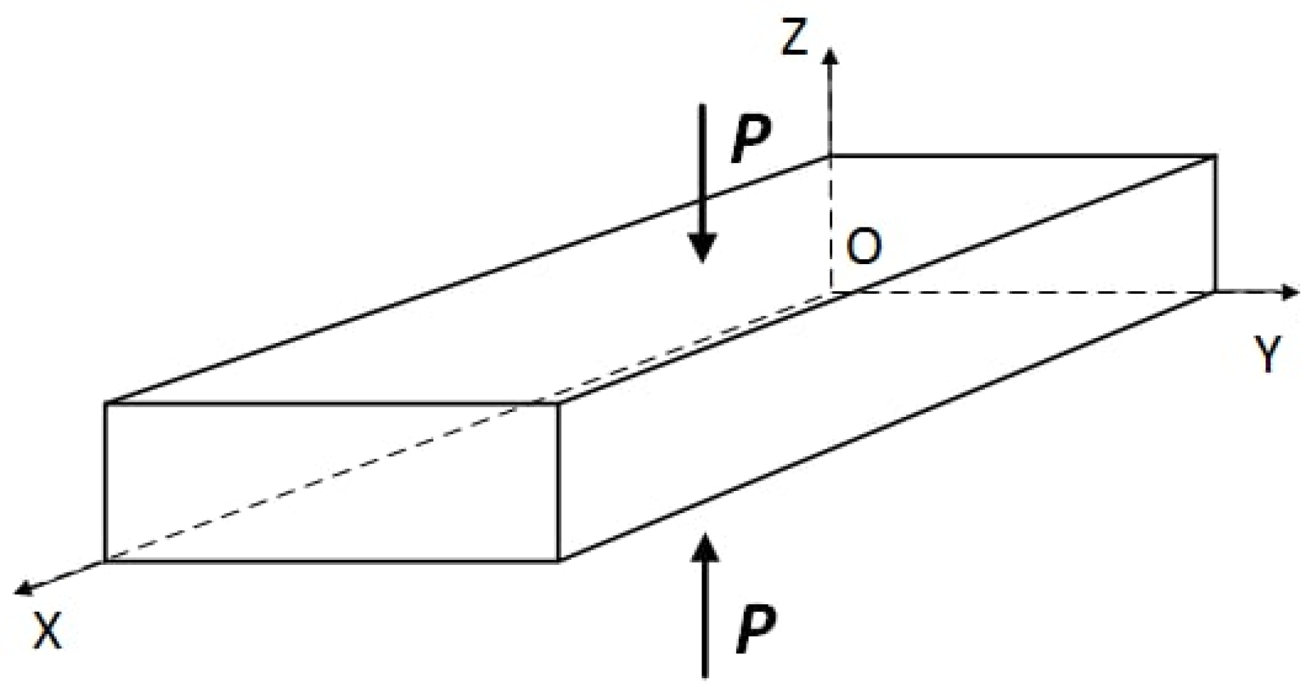
2. Materials and Methods

The source powders such as (1) Hadfield steel (HS) powder (Tulachermet, Russia) with a maximum particle size below 40 μm (Figure 1a); (2) commercial WC powder (Uzbek Plant of Refractory and Heat Resistant Metals, Chirchik, Uzbekistan) in the form of oblong agglomerates with an average length of about 40 µm, (Figure 1b); (3) plasma spray pyrolysis produced nanosized powder mixture (Siberian Chemical Plant, Seversk, Russia) composed of 76 wt.% ZrO2 + 20 wt.% Al2O3 + 4 wt.% Y2O3 (Y–TZP–Al2O3) were used to prepare WC/Y–TZP–Al2O3/Hadfield steel compositions as shown below in Table 1. The plasma spray particles contained both hollow thin-walled spherical shells (Figure 1c,d) and dense spheres (Figure 1c,e,f) composed of microcomposite eutectic mixture of nanosized ZrO2 (bright) and Al2O3 (dark) grains (Figure 1d–f).
An XRD phase analysis of powder compositions (Table 1) clearly showed the presence of peaks belonging to their components such as HCP WC and FCC γ-iron, while XRD patterns of the Y–TZP–Al2O3 powder blend allowed identifying peaks inherent with tetragonal ZrO2 (t-ZrO2) but having some peak tailings on their right shoulders (Figure 1g). No XRD peaks were found to detect the presence of an allotropic form of Al2O3. An inset in Figure 1e reproduces the low 2θ XRD pattern fragment obtained from the Y–TZP–Al2O3 composition that allows deconvolution of the asymmetrical peak into “narrow” and “wide” components. Such a deconvolution may be the evidence in favor of the formation of a solid solution of the type ZrO2(3Y,Al) with variable concentration of Al3+ ions in the tetragonal ZrO2 lattice [41].
The source powder compositions were blended with ethyl alcohol and then subjected to planetary ball milling using ∅6 mm balls that allowed reducing the WC agglomerate size to 2.5 ± 0.5 μm. On milling, the ethyl alcohol was evaporated from the samples before cold pressing the dried source powders at 8.5 MPa. The resulting green samples were characterized by 55% of theoretical density. The temperature during sintering was controlled using an optical pyrometer and focusing on a graphite die whose inner surface was coated with the BN film to prevent diffusion of carbon.
Final consolidation was carried out using a sinter-forging machine and argon as a shielding gas by placing 13 × 7.2 × 6.5 mm3 green samples between the top and bottom graphite ∅20 mm dies and applying induction heating to 1350 °C for 20 min. Then, these heated samples were held at that temperature for another 5 min for temperature equalization. Consolidation was performed by successively increasing the pressure at each stage in the order 5, 10, 15, 20, 25, and 30 MPa at 15 s intervals. The pressure was applied along the normal to the XOY plane as shown in Figure 2. Dwelling time at the final stage was limited to 10 min in order to avoid grain coarsening and retain the submicron structures. The next step was unloading, extracting the consolidated samples from the machine, and cooling them for 7–10 min in air. The bulk density of the sintered specimens was determined using the hydrostatic weighing method. The 25 W, 45 W, and 65 W sinter-forged samples had their densities equal to ~98 ± 2% of the theoretical density.
Mean Vickers hardness and indentation fracture toughness values of as-sintered composites were determined from at least ten indentations using a Vickers pyramid hardness tester «Duramin-500» (Struers A/S, Ballerup, Denmark) obtained on a polished surface of the specimens at 10 Kg load and 10 s dwell time. Fracture toughness of samples was estimated by measuring the lengths of radial indentation cracks and calculating with the Niihara formula [42]. The elastic modulus (E) was calculated according to the Reuss rule of mixture [43], using stiffness values of 660 GPa, 200 GPa, 200 GPa, and 300 GPa for pure WC, Hadfield steel, ZrO2, and Al2O3, respectively.
Tribological pin-on-disk testing of the composites was carried out using a sliding test machine UMT-1 (Tochpribor, Ivanovo, Russia). A disk made of as-cast high-speed steel (HSS) 63–65 HRC disk was used as a counterbody with sliding track diameter of 240 mm. Chemical composition of an as-cast HSS steel was as follows (wt.%): 15 V, 4.5 W, 3.6 Cr, 3.6 Mo, 1.8 Ni, 1.4 C, 1.0 Mn, Fe-balance).
Tests were conducted at nominal contact pressure of 5 MPa (normal load 315 N divided by total of three pins’ contact area 63 mm2 in the speed range of 7–37 m/s (7 m/s, 10 m/s, 20 m/s, 37 m/s) at ambient conditions of approximately 25 °C and 40–50% relative humidity. The disk wear track diameter was 240 mm. Total of three experiments (9 pins) each with a wear path length of 1000 m was conducted at each of the sliding speed values. To keep the wear path length constant, the test duration diminished with increasing the sliding speed so that, for speeds 7,10, 20, and 37 m/s, the test durations were ~143 s, ~100 s, ~50 s, and ~27 s, respectively.
Wear rate was evaluated by measuring the sample’s height before and after the test and then calculating the wear rate as volume loss (mm3) divided by sliding path length (m)-mm3/m.
Flash temperatures on the composite worn surfaces were estimated using the well-known equation [44]:
Δ T = μ P V 4 J ( K s a m p l e + K d i s k ) α
where μ is the CoF, P and V are the normal load and sliding speed, respectively, Ksample and Kdisk are thermal conductivities of the pin and disk, respectively. J is the Joule’s constant (in this case, J = 1) and α is the contact radius of the real contact area to be determined from an equation as follows (2):
α = ( P π H s a m p l e ) 1 / 2  
H s a m p l e is the sample’s hardness.
The results of this estimation are presented in Table 2, together with the real temperatures of the sliding zone, as measured using a pyrometer (Promin-KH1, Prompribor, Russia).
Microstructural characterization of the subsurface layers was performed on cross-section polished and etched views prepared by breaking the previously notched samples.
As-sintered composites were examined using scanning electron microscopes (SEM) (1) LEO EVO 50 (Carl Zeiss AG, Oberhochen, Germany), (2) TESCAN VEGA 3 SBU (TESCAN ORSAY HOLDING, Brno, Czech Republic) equipped with electron energy dispersive spectroscopes (EDS) OXFORD X-Max 50 (Oxford Instruments, Concord, MA, USA) with 20 kV accelerating voltage, 4–12 nA current, and approximately 2 μm probe spot diameter and (3) a HORIBA XGT 7200 X-ray fluorescence microscope (Kyoto, Japan) operated at tube current of 0.5 or 1 mA, beam diameter of 1.2 mm or 10 μm, respectively, and voltage of 50 kV with a detection limit of 0.01%.
The worn surfaces were additionally studied using high-resolution field emission scanning electron microscope (HR FESEM) Apreo 2S (Thermo Fisher Scientific, Waltham, MA, USA), equipped with Octane Elect Super (EDAX, Mahwah, NJ, USA) EDS detector, 20 kV accelerating voltage, 1.6 nA current, and approximately 0.1 μm probe spot diameter.
A symmetrical Bragg–Brentano XRD configuration (θ/2θ) with the Cu-Kα radiation was carried out to identify phases formed in the as-sintered composites. An X-ray diffractometer DRON-3 (Burevestnik, Saint Petersburg, Russia), with a scan range of 20–80° with (2θ) step size of 0.05° was used. Grazing-incidence X-ray diffraction with the Co-Kα radiation was used to detect phases on the worn surfaces of the composites at beam incidence angle of 10°. These experiments were carried out using a DRON-7 X-ray diffractometer (Burevestnik, Russia) with a scan range of 15–80° with (2θ) step size of 0.05°. Identification of the XRD reflections was performed using Crystal Impact’s software “Match!” (Version 3.9, Crystal Impact, Bonn, Germany).

3. Results

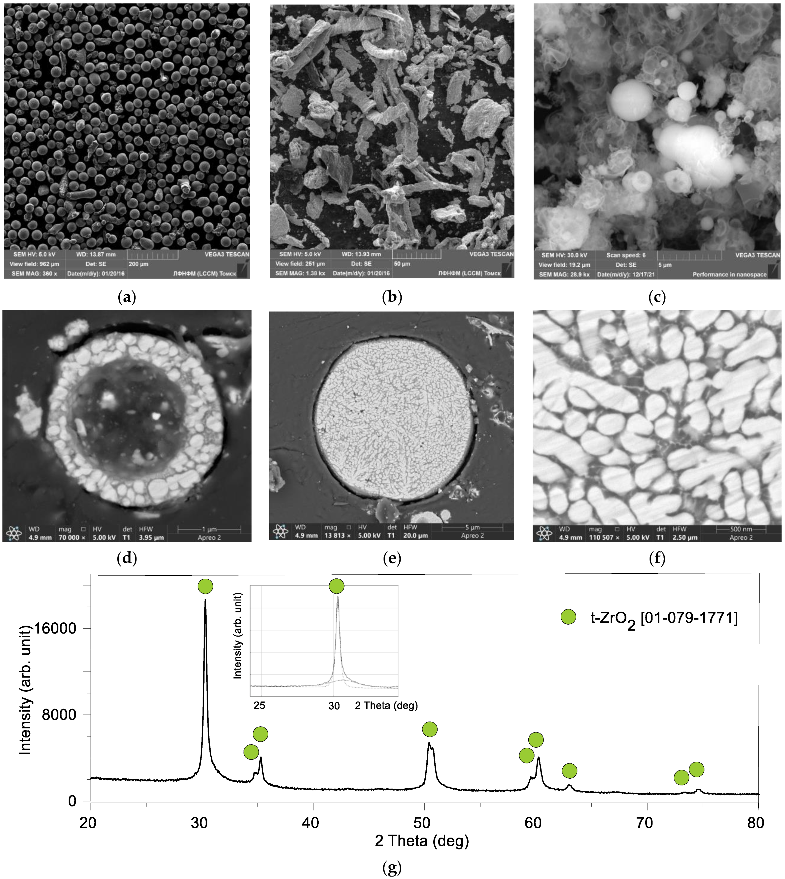
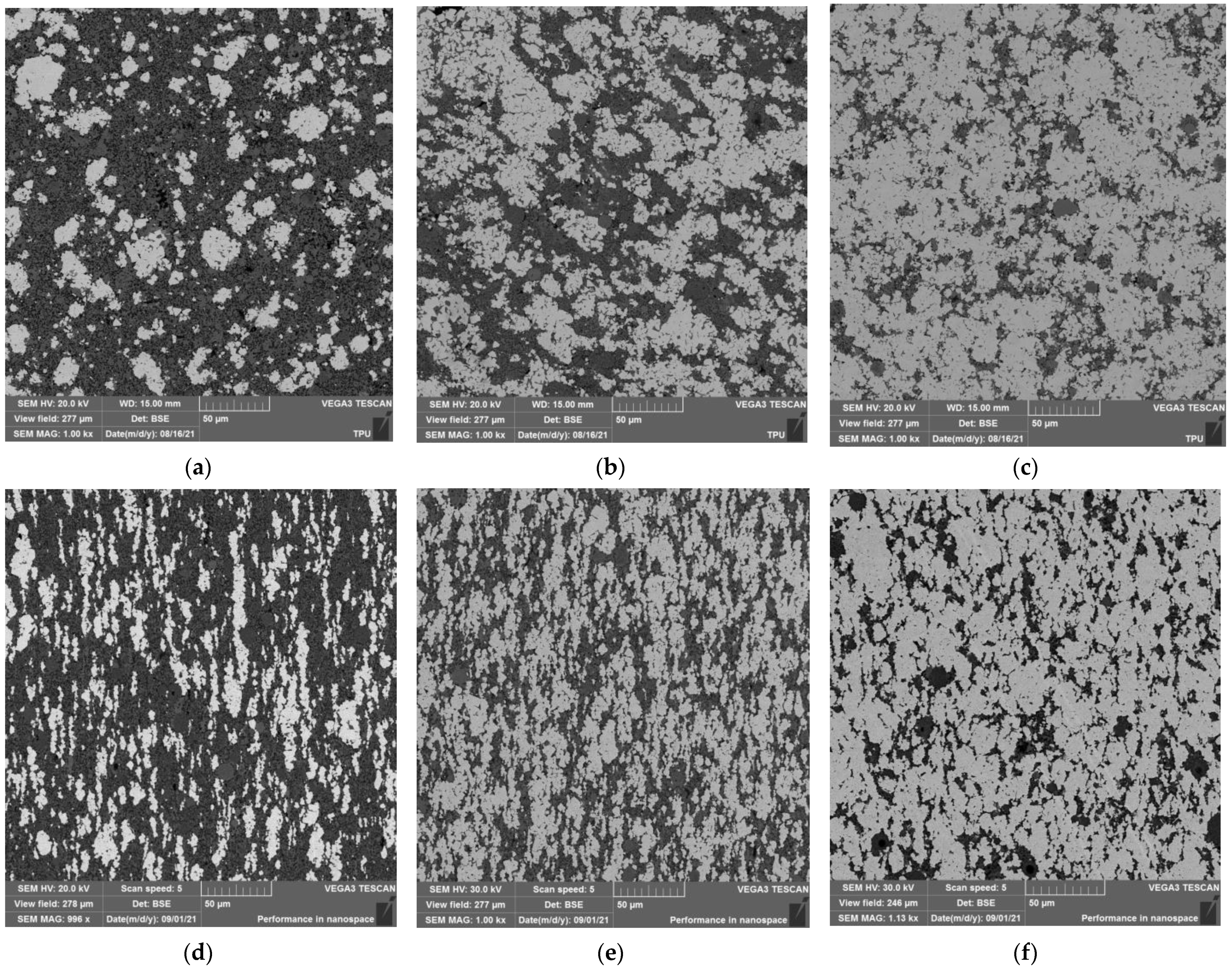
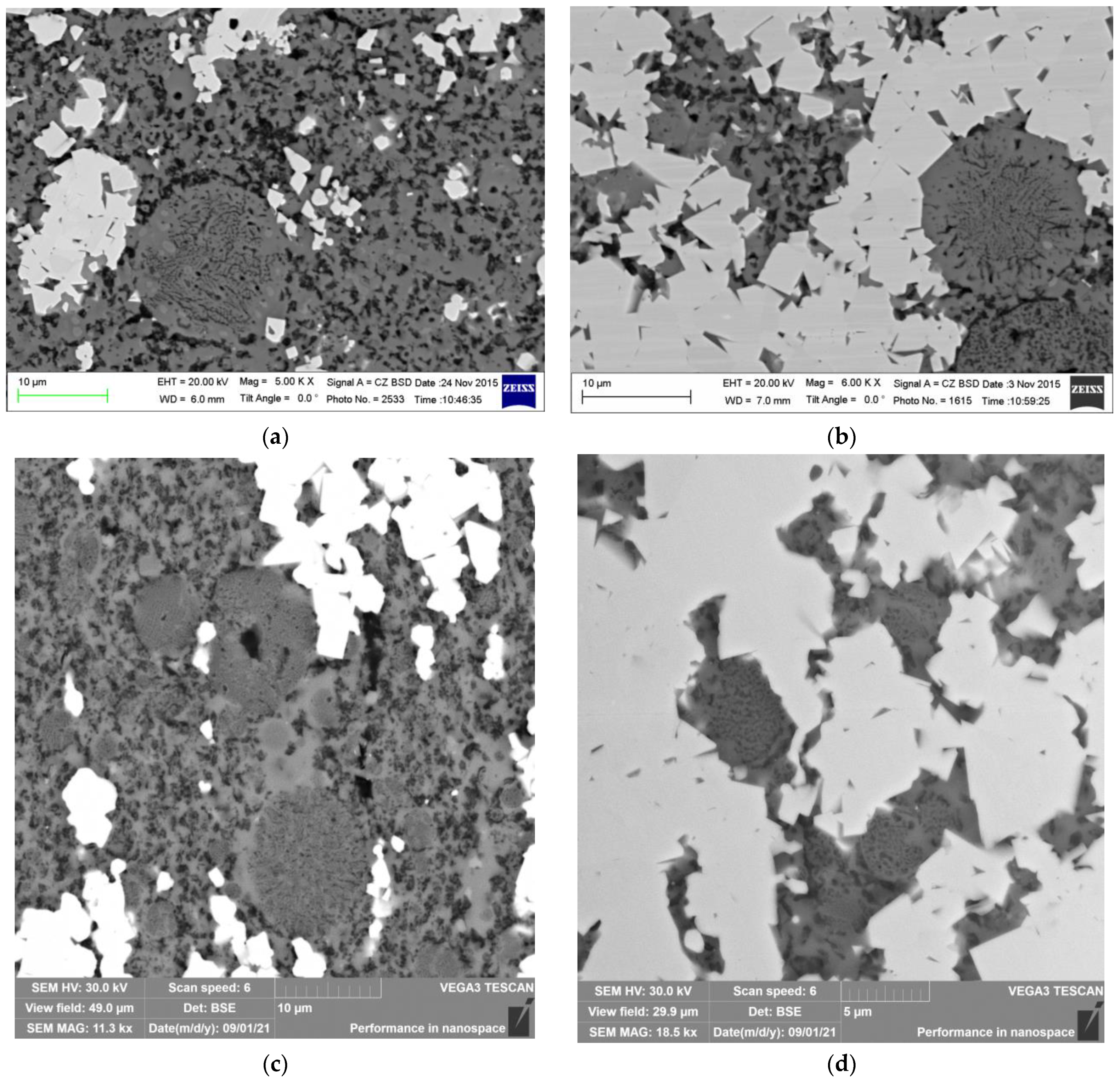
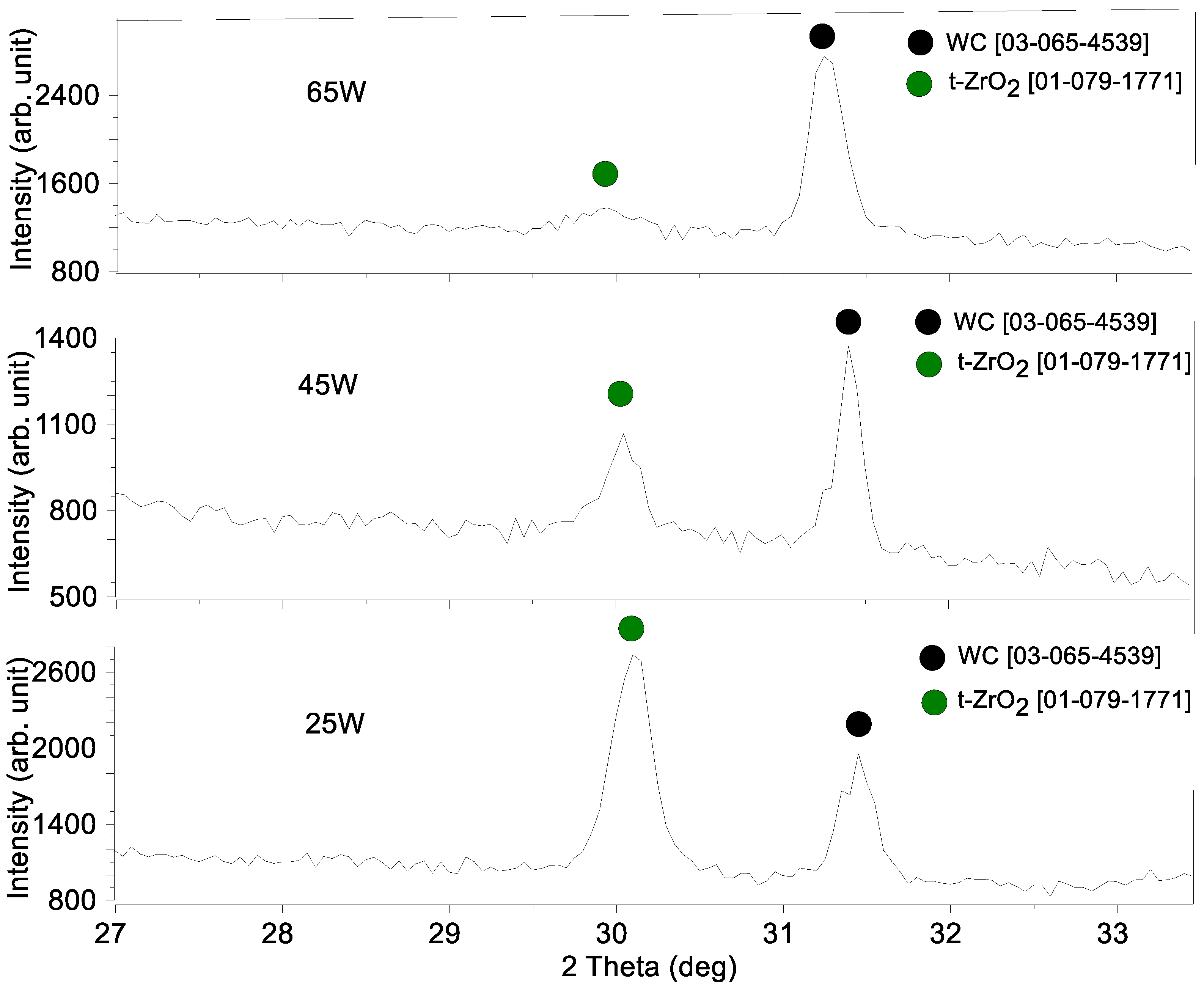
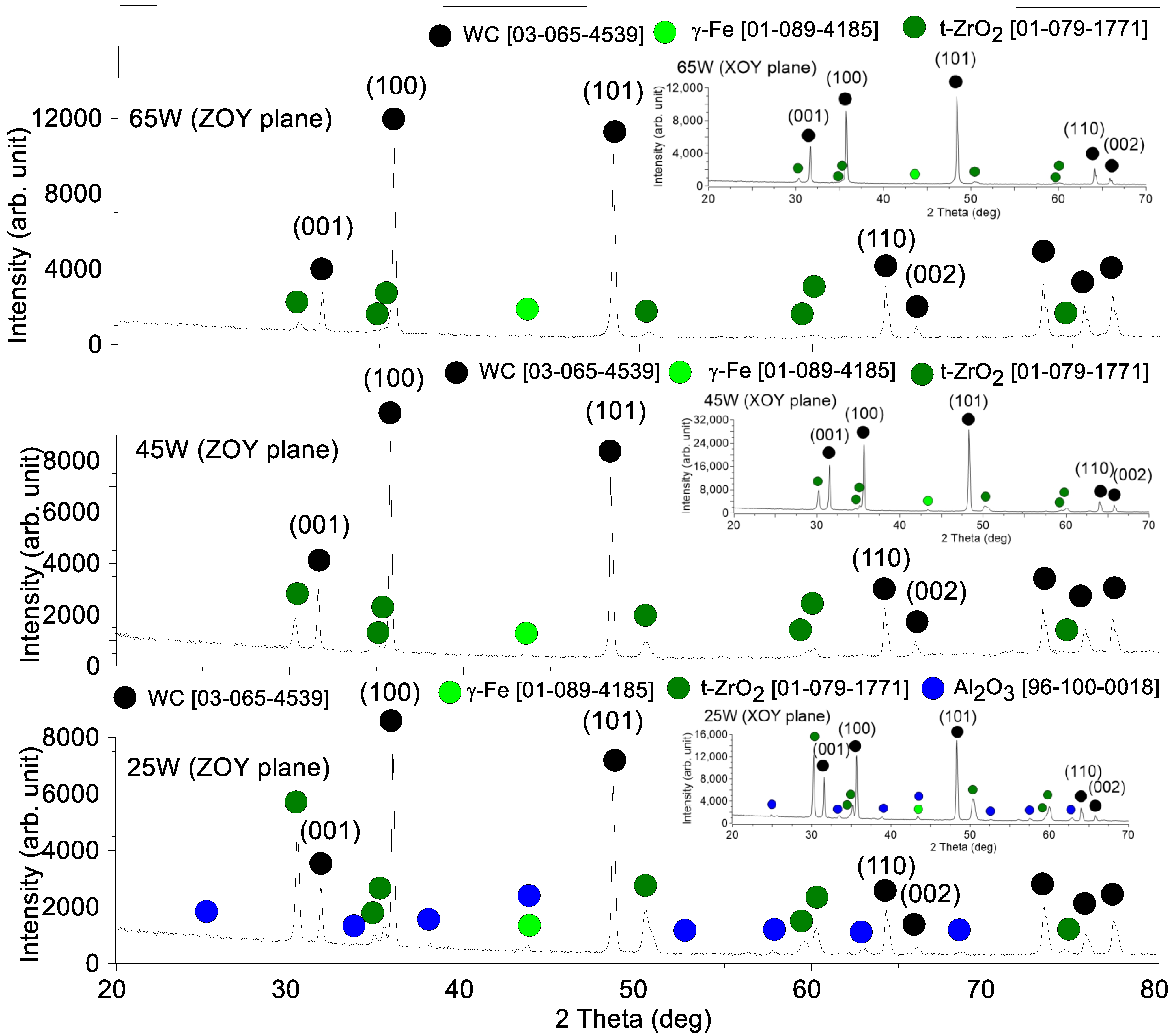
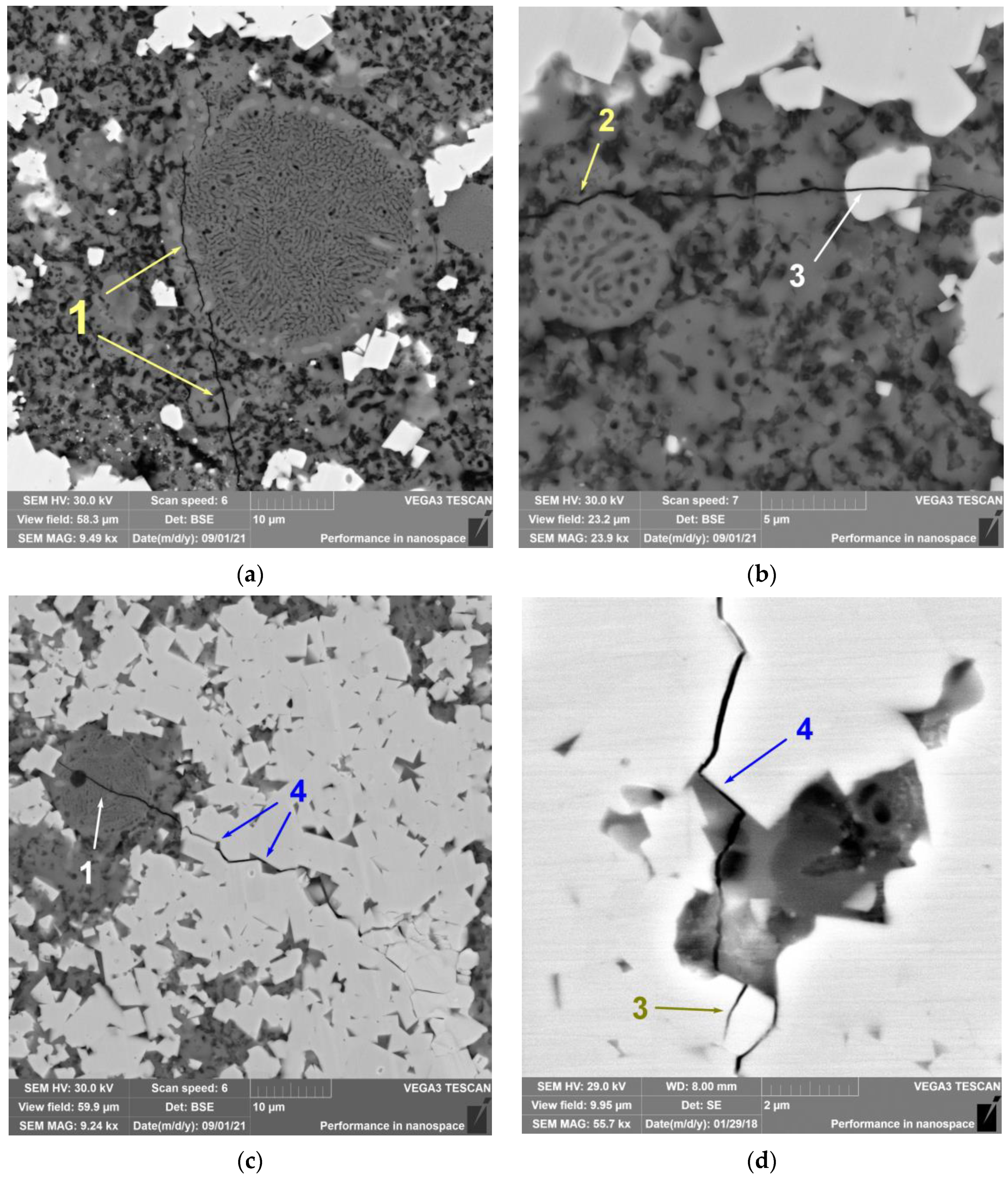
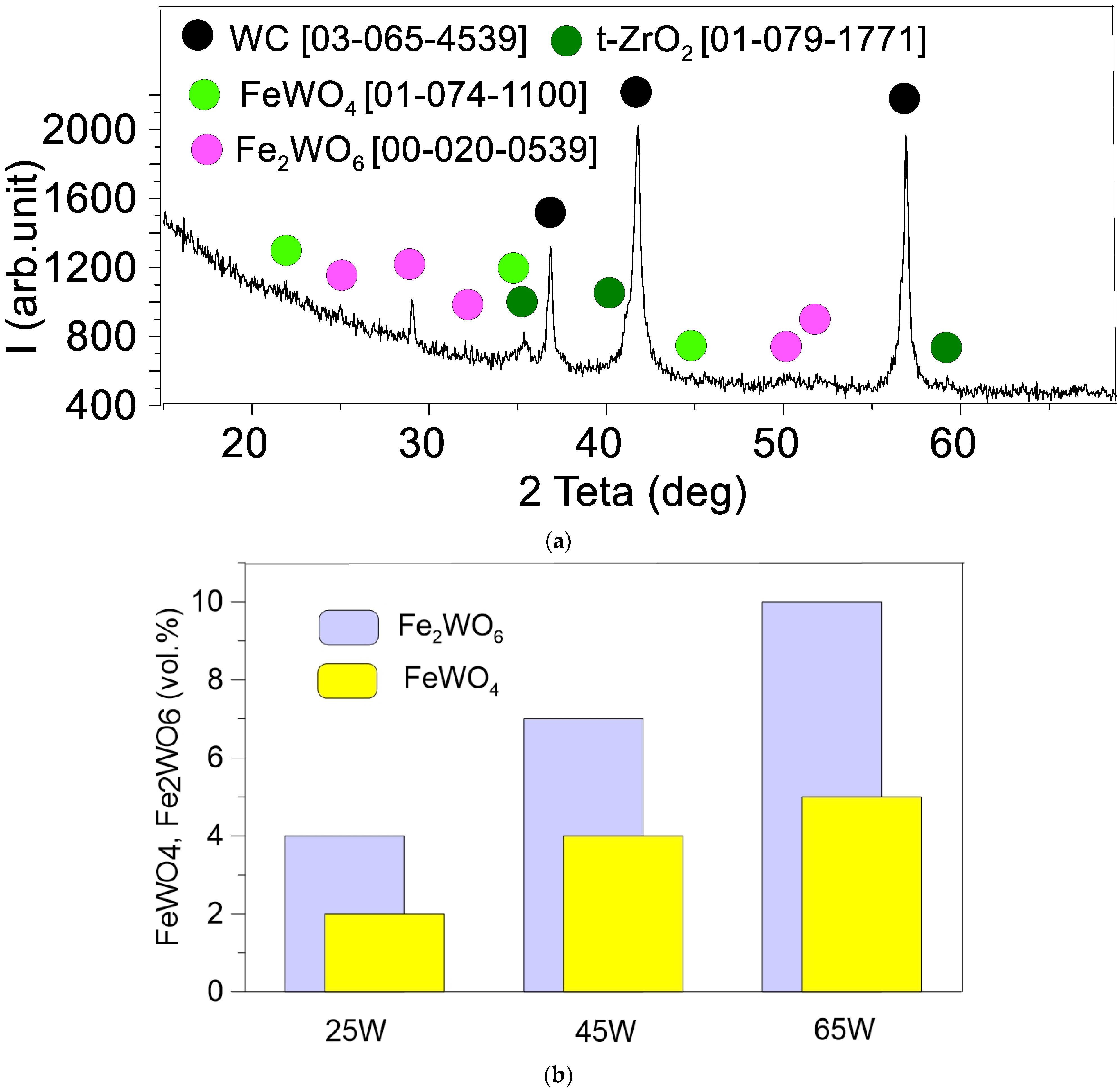
3.1. Microstructures and Phases in the As-Sintered Composites

An XRD phase analysis showed that all the as-sintered samples contained WC, γ-iron, and t-ZrO2 (Figure 3). Only tiny Al2O3 peaks were noticed in the 25 W sample while none of them were observed in samples with higher contents of WC, i.e., samples 45 W and 65 W. Such a finding can be explained by shielding the characteristic X-ray radiation from light elements Al and O by that of from high atomic number elements as Zr, and especially W. XRD patterns in Figure 3 have been obtained from the sample’s surfaces parallel to ZOY and XOY planes (Figure 2). The WC peak heights from sections parallel to XOY are close to that of the source WC powders so the mean peak ratios I(001)/I(100) and I(002)/I(110) were almost equal for each of the 25 W, 45 W ad 65 W samples, namely, 0.47, 0.53 and 0.51. In other words, the intensities of basal and pyramidal plane peaks (001,002) and (101) are reduced with simultaneous increases in those of prismatic planes (100,110), revealing the texture changes after sinter-forging.
SEM BSE images from the polished views of as-sintered samples (//XOY) demonstrated the presence of bright WC grain almost equiaxed agglomerates whose mean sizes were ~25 μm, ~55 μm, and ~100 μm in samples 25 W, 45 W, and 65 W, respectively (Figure 4a–c). SEM BSE images of the surfaces parallel to ZOY demonstrate bright WC grain agglomerates of higher aspect ratio ~1:5 resulting from sinter-forging with compression applied along the OZ axis (Figure 2).
The dark BSE contrast corresponded to the distribution of other components such as ceramics and Hadfield steel along with the WC grain agglomerates. The EDS maps (Figure 5 and Figure 6) and EDS profile scans (Figure 7) obtained from the as-sintered samples allowed observing that the preferential concentration of Hadfield steel is in the intergrain spaces of WC grain agglomerates, while no HS particles are found in the areas occupied by Y–TZP–Al2O3. Obviously, the homogeneity of the iron distribution in the composite improved with the content of WC. The steel grains show no oxygen but some amount of carbon which is really dissolved in the austenite (Figure 7).
ZrO2 and Al2O3 ceramics can be seen as light grey and 0.1–0.3 μm dark grey BSE contrast formations, respectively. In addition, there are spherical eutectic grains with inner 50–100 nm-sized structural components (Figure 8), i.e., almost the same as those observed in the source Y–TZP–Al2O3 powders (Figure 1c–f). Metallographic views of the sections parallel to XOY Figure 8a,b allow revealing composite spherical Y–TZP–Al2O3 particles identical to those in source powders (Figure 8a,b) while those observed on the views from sections parallel to the ZOY plane are elliptical with their short axes parallel to the OZ forging direction (Figure 8c,d).

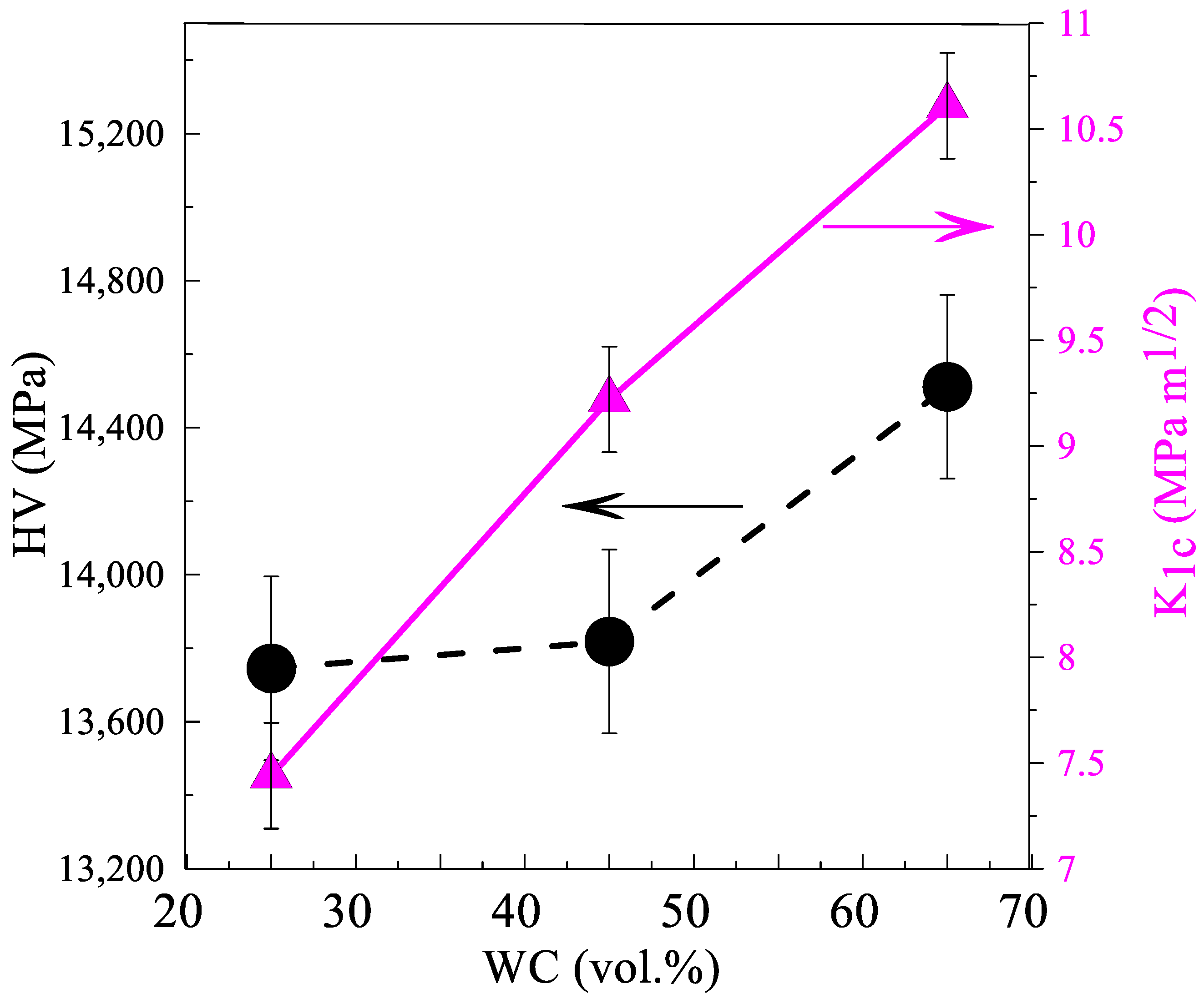
3.2. Hardness, Fracture Toughness and Crack Propagation

Both hardness and Niihara [42] fracture toughness grows with the WC content in the CMCs (Figure 9).
It is interesting that no traces of a monoclinic ZrO2 phase (m-ZrO2) were detected on the fracture surfaces of the composites after three-point flexural tests (Figure 10), which was evidence that no t-ZrO2→ m-ZrO2 strain-induced martensitic transformation occurred there.
Radial crack propagation from the Vickers indentations was examined to establish the fracture mechanism (Figure 11). It turned out that the transcrystalline fracture was a dominating mechanism for coarse WC grains (Figure 11b, area 3) while WC agglomerates demonstrated cracks propagating along the WC grain boundaries filled with the steel (Figure 11c,d area 4). It is plausible that intercrystalline cracks may be retarded in these steel-filled spaces due to plastic deformation. Examining the ceramic eutectic Y–TZP–Al2O3 component of the composite allows exposing either a transcrystallite fracture (Figure 11a,c area 1) or the propagating cracks were deflected by the coarse Y–TZP–Al2O3 spherical agglomerates (Figure 11b area 2). Both of these mechanisms can provide fracture toughness improvements from the viewpoint of increasing the energy spent on crack propagation.
The fracture surfaces resulting from the bending test allowed observing the transcrystallite fracture mode on the WC grains (Figure 12a–e, area 1) and Y–TZP–Al2O3 spherical agglomerates with eutectic structures (Figure 12a,b, area 2). The Hadfield steel particles demonstrated ductile cleavage (Figure 12a–e, area 3).

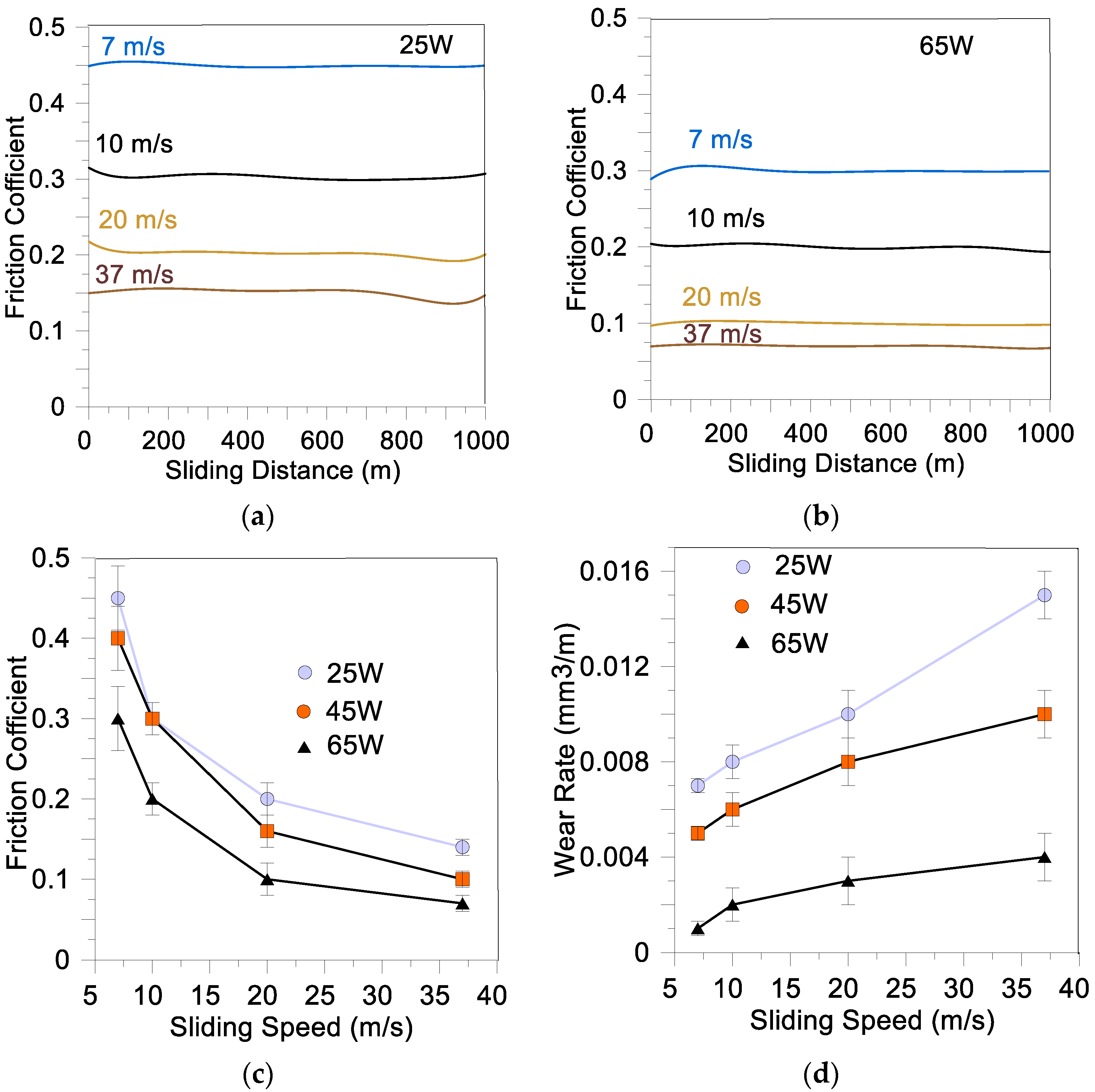
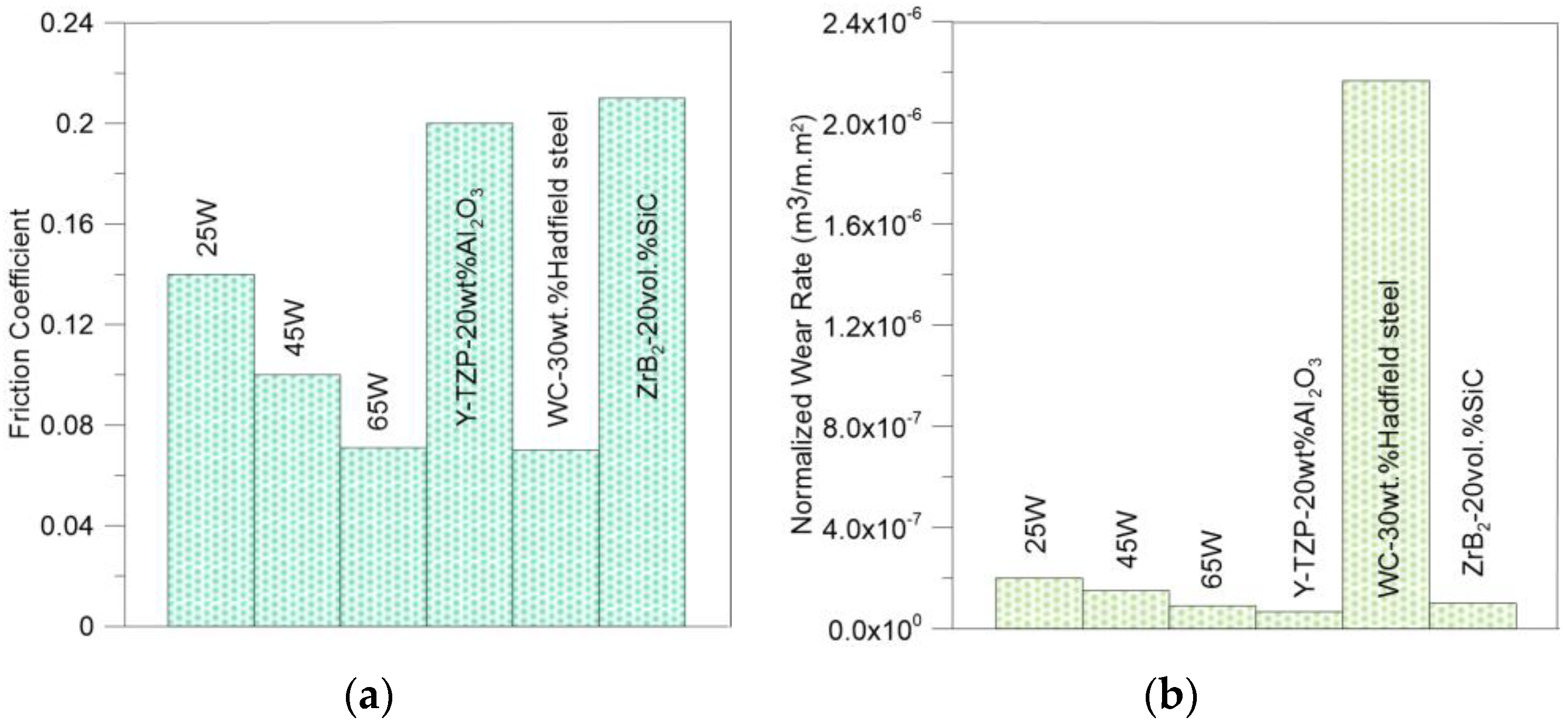
3.3. Coefficient of Friction and Wear Rate

Sliding was carried out on composite surfaces parallel to the ZOY plane (Figure 2). Samples 25 W, 45 W, and 65 W demonstrated rather steady sliding with moderate friction force oscillation amplitudes (Figure 13a,b). Tribological tests allowed obtaining the dependencies of wear rate and CoF on sliding speed for all the composites (Figure 13c,d) to characterize their anti-friction behaviors. All composite 25 W, 45 W, and 65 W samples demonstrated CoF maximums at sliding speeds in the range of 7–10 m/s, while minimum CoF values were achieved at 37 m/s speed (Figure 13c). The wear rate for all composites only slightly increased in sliding at speeds from 7 to 37 m/s (Figure 13d). The minimal wear rate and absolute minimum CoF = 0.07 were achieved on the 65 W composite at 37 m/s.

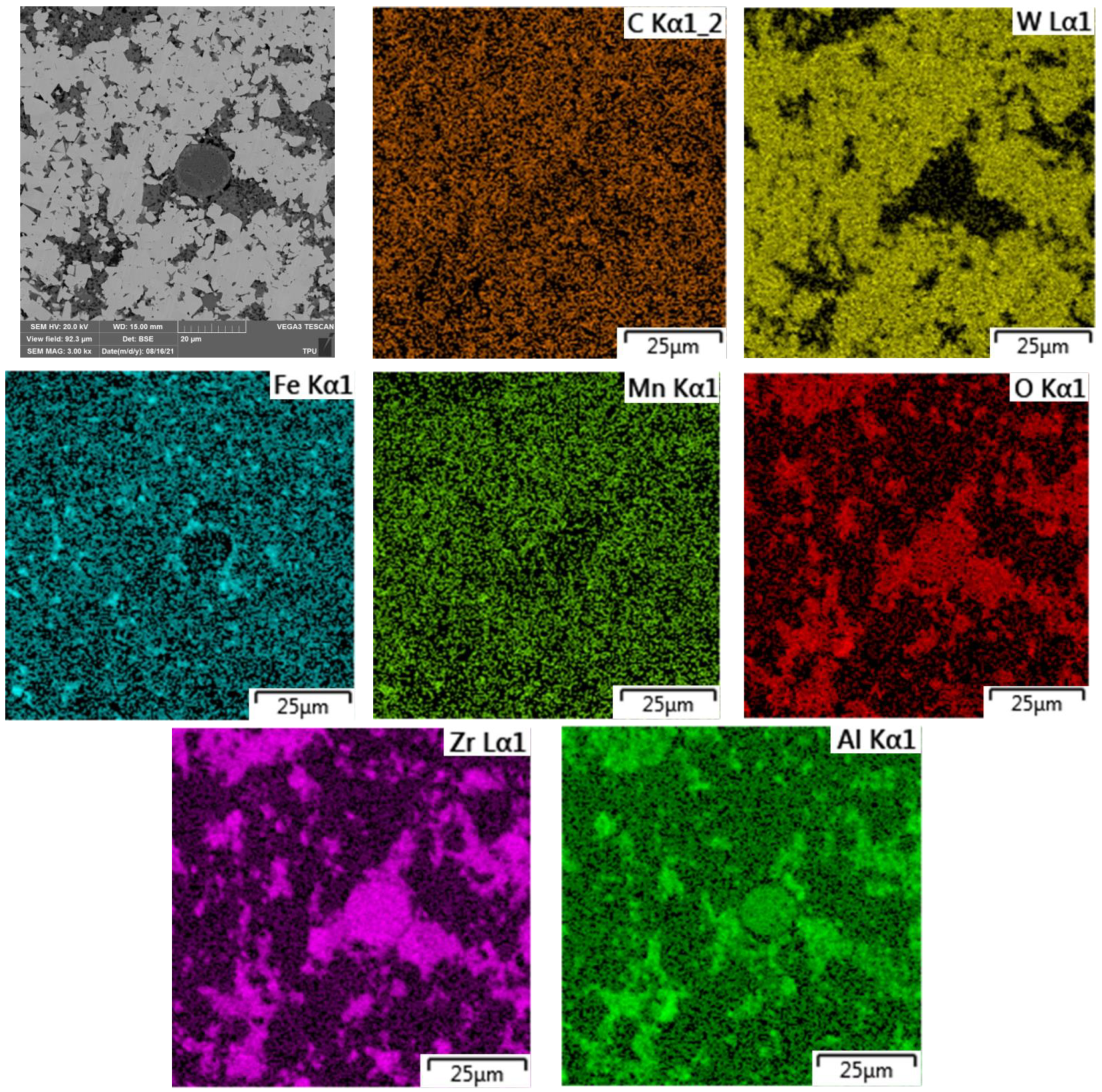
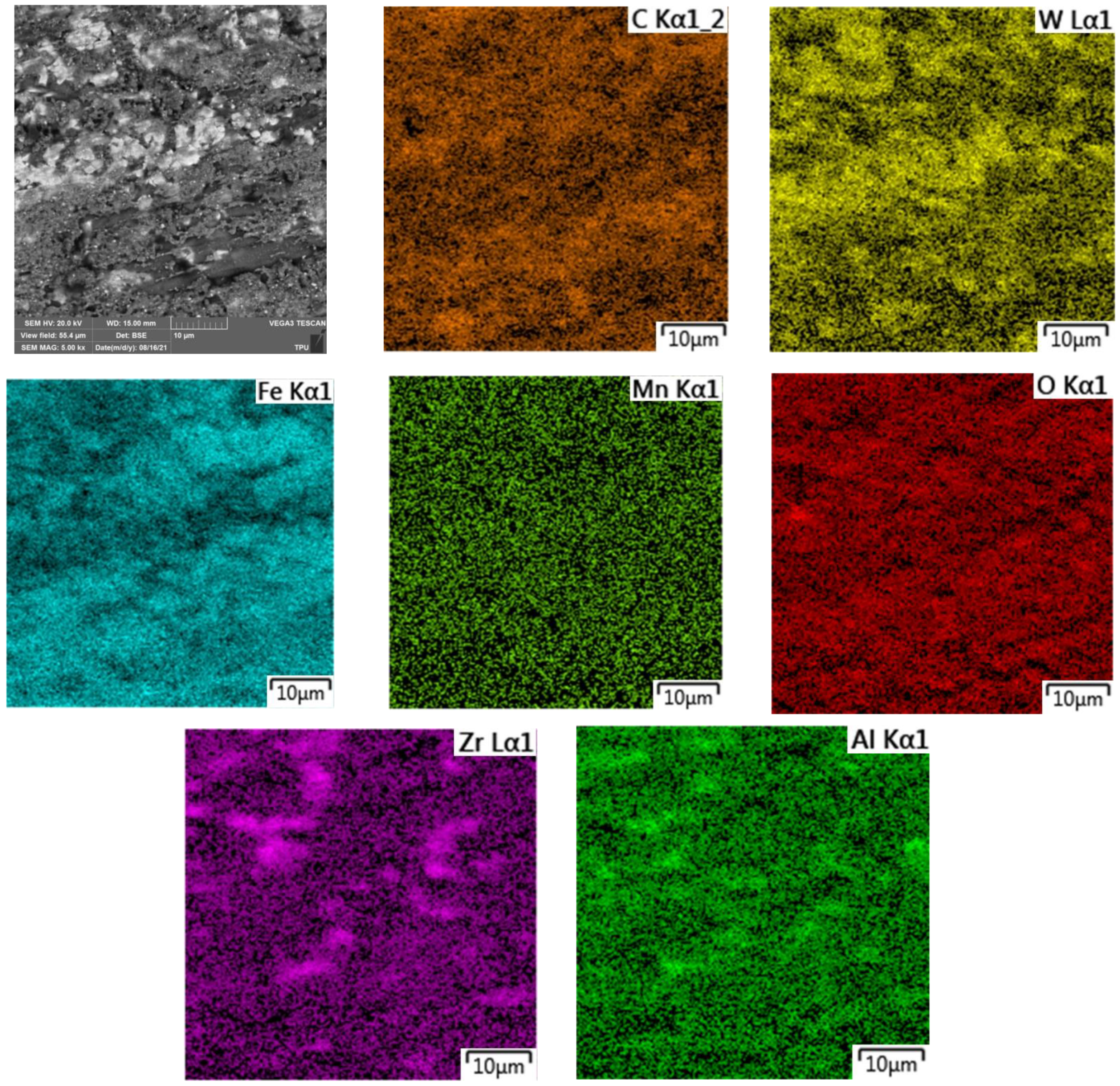
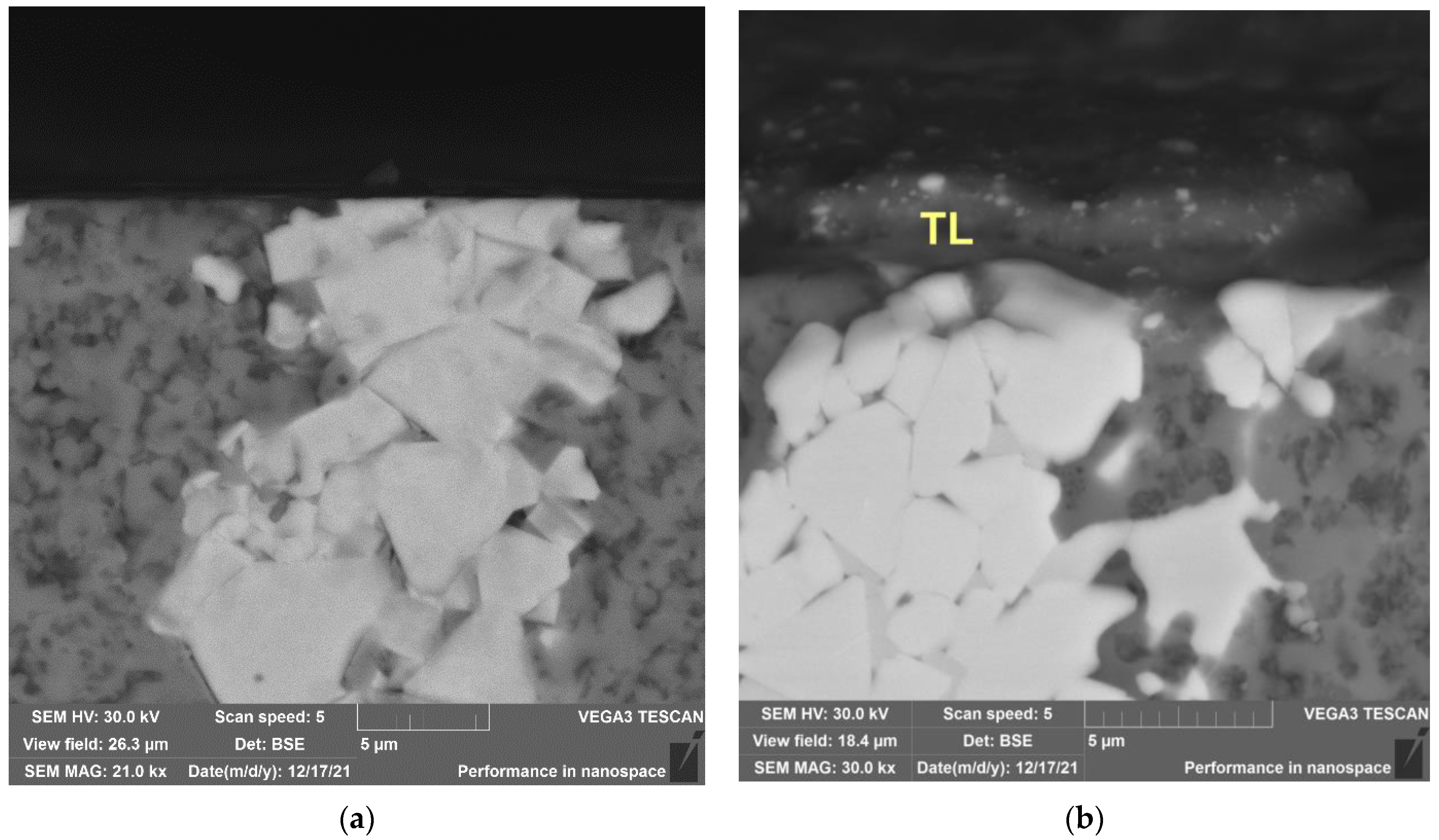
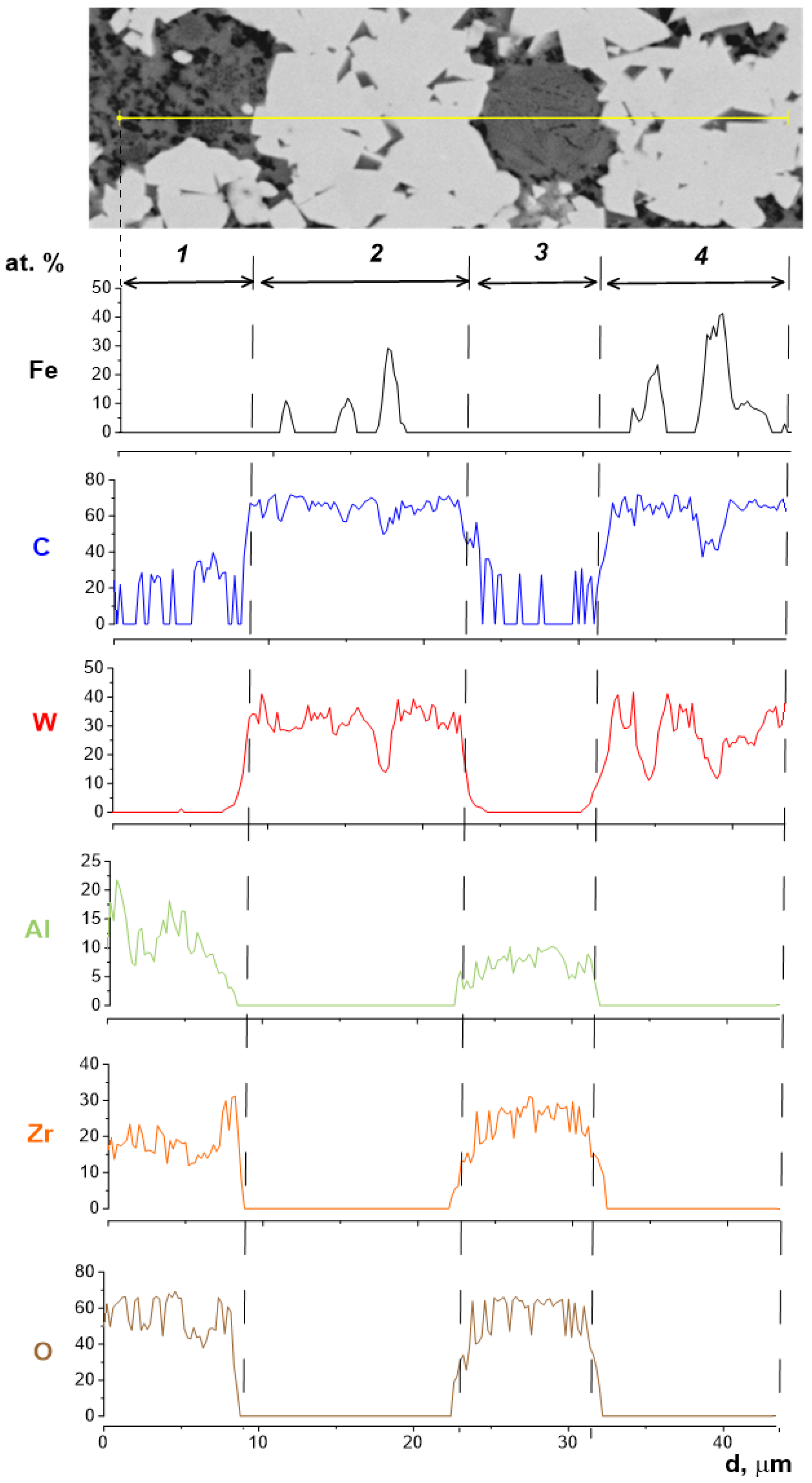
3.4. Microstructures and EDS of Worn Surfaces

Along with detecting WC and t-ZrO2, the XRD of worn surfaces allowed for the detection of the presence of mixed oxides FeWO4 and Fe2WO6 (Figure 14a) whose contents increased with the content of WC in the composites (Figure 14b).
The mean WC XRD peak ratios such as I(001)/I(100) and I(002)/I(110) obtained from composites 25 W, 45 W, and 65 W were 0.22, 0.26, and 0.3, respectively, i.e., practically coincided with those from the corresponding polished surfaces parallel to ZOY plane (Figure 3). Therefore, sliding did not result in any redistribution of the texture components. Such a finding may be explained by reducing the mechanical stresses because of the self-lubrication effect.
Sliding at 37 m/s resulted in the generation of a tribological layer (TL) on the worn surfaces of samples (Figure 15 and Figure 16) whose total area depends on the content of WC in the composite. Only small TL patches can be observed on the worn surfaces of the 25 W sample together with bright WC agglomerate islets, while almost full TL coverage of the worn surfaces occurred on the 65 W sample.
A semi-quantitative EDS mapping of the worn surfaces shows them enriched with oxygen (Figure 15 and Figure 16). Additionally, it can be seen in Figure 15 that iron is concentrated within the WC islets.

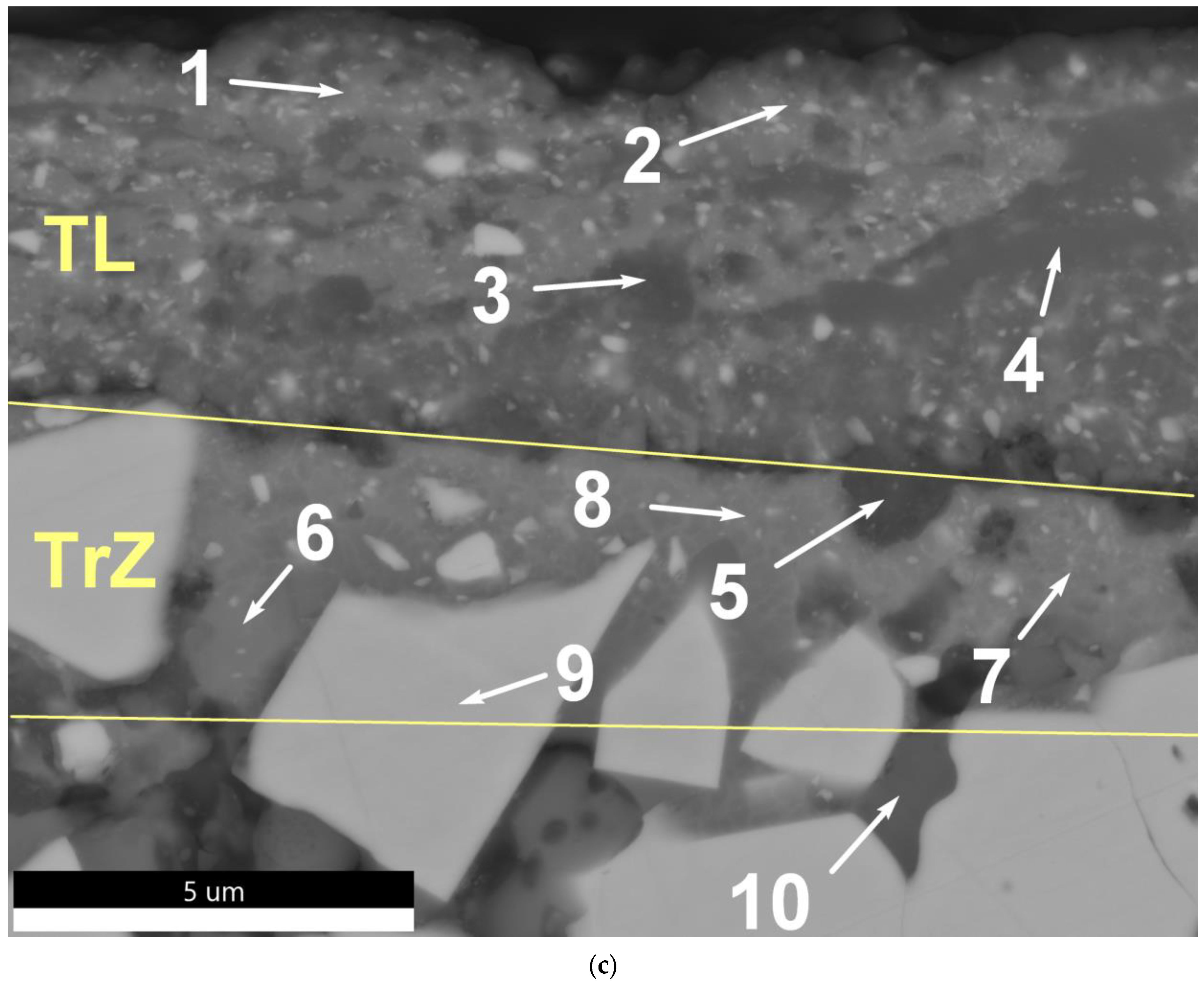
3.5. Tribological Layer Microstructures and Phases

Subsurface section views were prepared from the worn samples that allowed obtaining SEM images of tribological layers (TLs) generated on them in the course of high-speed sliding (Figure 17a–c). The subsurface section of the 25 W sample did not allow the demonstration of any TL except for some fragmentation in the top part of the WC agglomerate (Figure 17a).
Clearly observed is the TL on both 45 W and 65 W samples (Figure 17b,c). Almost the entire worn surface area of sample 65 W was covered by the TL (Figure 17c) and below the TL there is a transition zone (TrZ) where less intense plastic deformation, as well as WC and ceramic grain fracture and oxidation, occurred.
Table 3, Figure 17 and Figure 18 demonstrate the results obtained from the EDS examination of these zones. The TL is microstructurally represented by two different components such as homogeneous dark grey regions or TLA1 (Figure 17c, areas 3,4) and light grey regions composed of bright nanosized fragments (TLA2) (Figure 17c, areas 1,2). The EDS data in Figure 18 and Figure 19, and Table 3 shows these regions as those enriched with tungsten, iron, chromium, manganum, and oxygen. The difference between TLA1 and TLA2 regions is that TLA1 contains more vanadium, chromium, and tungsten and less manganum as compared to the composition of TLA2 (Table 3, areas 1–4, Figure 18 and Figure 19), i.e., the TLA1 is enriched with oxidized elements transferred from the HSS disk. On the other hand, higher concentrations of manganum (Table 3, areas 1–4) as compared to that of TLA1 and the presence of bright fine WC particles may be evidence in favor of TLA2 generation by tribooxidizing of the composite’s structural components.
From the viewpoint of its chemical composition, the TrZ looks like a transition from undeformed as-sintered base material to the TL. Apart from the relatively coarse but already fragmented WC (Table 3, area 9) and Y–TZP–Al2O3 grains (Table 3, area 10), there are TrZ regions that are compositionally similar to those of TLA1, but have fewer concentrations of oxygen (Table 3, areas 6–8). In addition, the dark grey particles chemically similar to the TLA1 can be observed at the TL/TrZ boundary (Table 3, area 5).

4. Discussion

4.1. Structure of As-Sintered Composites. Fracture Toughening Mechanism of WC/Y–TZP–Al2O3 Hybrid Ceramic–Matrix Composite with Dispersed Hadfield Steel Particles

Relatively fast and low-temperature sinter-forging allowed obtaining a dense CMC composed of coarse WC grains, Y–TZP–Al2O3 microcomposite spheres, and grains as with dispersed Hadfield steel particles (Figure 4 and Figure 8), i.e., exactly phases the same as those of source powders before any consolidation (Figure 3). Images in Figure 3 and Figure 4, and Figure 4 and Figure 8 allow observing that the composites had high aspect ratio WC and Y–TZP–Al2O3 components as expected from sinter-forging. It is plausible that efficient pore displacement to the periphery of the sample occurred there, allowing obtaining a dense WC/Y–TZP–Al2O3 hybrid ceramic–matrix composite with dispersed Hadfield steel particles. Let us note that these as-sintered composites revealed some specialness related to preferential concentration of HS in the intergrain spaces of WC grain agglomerates while no HS particles were found in areas occupied by Y–TZP–Al2O3 (Figure 5, Figure 6 and Figure 7).
It was reported earlier [45,46] that the WC grains may form agglomerates when sintering the WC–ZrO2 and WC–Al2O3 composites even if the source powder blend was thoroughly homogenized. In our case, there is another factor facilitating the agglomeration because sinter-forging was carried out at 1350 °C, i.e., above the 1143 °C that is the WC–Fe eutectic point [37]. Therefore, some liquid phase sintering might have occurred when Hadfield steel preferentially interacted with the WC grains, and possibly partially infiltrated into the already formed WC grain agglomerates due to its better wettability of the WC [7,10,47] as compared to that of ZrO2 [48] or Al2O3 [49], i.e., of Y–TZP–Al2O3 components, which formed their own agglomerates outside of the regions occupied by WC–Hadfield steel cermet.
Another interesting fact is that there was not any grain growth in the CMC areas occupied by the Y–TZP–Al2O3 matrix, i.e., neither ceramic grains nor microcomposite eutectic spheres increased their sizes, and therefore all as-sintered composites 25 W, 45 W, and 65 W did not experience any t-ZrO2 → m-ZrO2 martensitic transformation during either flexural test (Figure 10) or high-speed sliding (Figure 14).
All of this allowed preparing the WC/Y–TZP–Al2O3 hybrid ceramic–matrix composites with a unique structure combining regions structurally similar to the WC–Hadfield steel MMCs [10] with microcomposite eutectic Y–TZP–Al2O3 core structures inside the micron-thickness spherical shells similar to those found in the source ceramic powders (Figure 1c–f).
These materials possess simultaneously high hardness and fracture toughness (Figure 10) achieved by combining the crack deflection on the coarse WC and Y–TZP–Al2O3 grains (Figure 11) with transcrystallite fracture of these grains (Figure 12a–e, area 1, Figure 12a,b, area 2) as well as improving the bulk fracture toughness due to the presence of a ductile steel component (Figure 12a–e, area 3). The complex eutectic core structure of Y–TZP–Al2O3 spherical particles inside the agglomerates may be another factor in favor of enhanced fracture toughness (Figure 12a,b, area 2).
The preferential distribution of steel particles inside the WC agglomerates had an effect on the fracture toughness of the composites. Smaller content of the ductile steel component in the 25 W CMC resulted in the fact that the crack was propagating mainly via Y–TZP–Al2O3 areas (Figure 11a,b). Along with that, even if having minimal fracture toughness at the level of ~7.5 MPa m1/2 this 25 W composite was still tough as compared to common ceramics with fracture toughness at the level of ~2–3 MPa m1/2.

4.2. Coefficient of Friction and Normalized Wear Rate of WC/Y–TZP–Al2O3 Hybrid Ceramic–matrix Composites with Dispersed Hadfield Steel Particles. Comparison to Other Composites

The CoF values of all WC/Y–TZP–Al2O3 hybrid ceramic–matrix composites with dispersed Hadfield steel particles obtained at sliding speed 37 m/s and contact pressure 5 MPa were lower than those of Y–TZP–20 wt.% Al2O3 [11] and ZrB2–20 vol.% SiC [8] (Figure 20a). In particular, the CoF of the 65 W composite was at the level of that of WC-30 wt.% Hadfield steel MMC [10].
To provide a meaningful comparison of the wear characteristics of composites, the normalized wear rates were obtained as wear rates divided by the corresponding appearing contact areas [50]. It can be observed from Figure 20b that 25 W, 45 W, and 65 W composites demonstrated rather low wear rates as compared to that of pure ceramic composite Y–TZP–Al2O3 while the wear rate of WC–30 wt.% Hadfield steel MMC was about an order of magnitude higher (Figure 20b).
These results obviously show that the WC/Y–TZP–Al2O3 hybrid ceramic–matrix composites with dispersed Hadfield steel particles allowed for achieving a hybrid effect when the composites inherited the self-lubrication effect from the WC–30 wt.% Hadfield steel MMCs whose poor wear resistance was improved by the addition of wear-resistant TZP–Al2O3 matrix.
When comparing the tribological characteristics of the 25 W, 45 W, and 65 W composites with those of ultra-high temperature ZrB2–20 vol.% SiC CMC one can see that the hybrid composites showed a comparable level of wear resistance and essentially lower CoFs (Figure 20a,b).

4.3. Subsurface Multi-Layer Tribooxidation Structure of WC/Y–TZP–Al2O3 Hybrid Ceramic–matrix Composite with Dispersed Hadfield Steel Particles That Provided the Self-Lubricating Effect and Self-Healing Effect in High-Speed Sliding

The above-discussed behavior can be related to the generation of multilayer subsurface structures on the worn surfaces of the WC/Y–TZP–Al2O3 hybrid ceramic–matrix composite with dispersed Hadfield steel particles. Such a subsurface structural evolution of the composites may be represented in the following manner.
The composites are intensely heated during sliding at 37 m/s so that subsurface temperatures may be close to that of Hadfield steel melting. Such a thermal plasticization facilitates the transfer of the HSS components from the counterbody onto the composite as well as the outcome of Hadfield steel components from the bulk of the composite. All these components may intermix and oxidize according to reactions as follows:
2Fe + O2 = 2FeO
4FeO + 3O2→2Fe2O3
Subsurface fragmentation of the WC grains give fine fragments that can be easily oxidized to WO3 starting from 800 °C [51]:
WC + 2O2 = WO3 + CO
The positive effect of such an oxidization is that conditions are created for synthetizing self-lubricating iron tungstates from iron oxides (reactions (3) and (4)) and WO3 (reaction (5)) starting from ~600 °C and according to the reactions as follows [52,53]:
FeO + WO3 = FeWO4
Fe2O3 + WO3 → Fe2WO6
The higher the WC content in the composite, the more iron tungstate generated in the subsurface layers (Figure 14b), and the more worn surface area is covered by the tribological layer (Figure 17). Another reason may stem from the fact that the heat conductivity increased with the WC content as well as the contact zone temperature (Table 2), which then resulted in easy flow-out of the quasi-viscous TL.
Let us note that the presence of nanosized particles in the TLA2 served as a marker to reveal the TL quasi-viscous flow pattern when more viscous TLA2 did not fully intermix with TLA1 while involved in sliding-induced motion. Nevertheless, no voids were formed during such a motion, and on the contrary, even some self-healing behavior was demonstrated when this quasi-viscous mass filled up the interfragmentary spaces and cracks (Figure 17c). Such an effect is similar to that demonstrated in high-speed sliding on ultrahigh temperature ZrB2-20 vol.% SiC ceramics by the in situ formed melted borosilicate glass [8,9].
The above-discussed results allow claiming that WC/Y–TZP–Al2O3 hybrid ceramic–matrix composite with dispersed Hadfield steel demonstrated structural adaptation to high-speed sliding, and simultaneously improved wear resistance and the friction reduction mechanism due to the unique combination of its components.

5. Conclusions

New WC/Y–TZP–Al2O3 hybrid ceramic–matrix composites with dispersed Hadfield steel have been prepared by sinter-forging for high-temperature (high-speed) sliding against steel and composite counterbodies. All composites demonstrated a high aspect ratio WC and microcomposite Y–TZP–Al2O3 grains resulting from sinter-forging. The structural design of such a composite allows combining high hardness with good fracture toughness, and acceptable wear resistance with self-lubrication self-healing behavior due to the tribochemical generation of multilayer quasi-viscous and thick tribological layers. This layer served to cover and protect the underlying composite grains against direct mechanical fragmentation and removal of the fragments as well as create conditions for slow oxidizing of the WC fragments and incorporating them with the tribological layer. Such a synergetic adaptation effect was achieved due to the in-situ synthesis of iron tungstates FeWO4 and Fe2WO6 that are capable of encapsulating hard wear particles and fragments, filling voids and cavities, thus simultaneously reducing wear and friction in the hybrid composite/steel sliding pair.

Author Contributions

Conceptualization, N.S. and S.T.; methodology, N.S. and S.T.; software, I.S.; validation, I.S.; formal analysis, N.S. and I.S.; investigation, N.S., I.S., M.G., T.S., A.B., M.R., A.V. and E.M.; resources, N.S. and V.R.; data curation, N.S. and I.S.; writing—original draft preparation, N.S. and S.T.; writing—review and editing, N.S. and S.T.; visualization, N.S., S.T., M.G., T.S., A.B., M.R., A.V. and E.M.; supervision, N.S. and S.T.; project administration, N.S. and S.T.; funding acquisition, N.S. All authors have read and agreed to the published version of the manuscript.

Funding

The work was performed according to the government research assignment for ISPMS SB RAS, FWRW-2021-0006.

Institutional Review Board Statement

Not applicable.

Informed Consent Statement

Not applicable.

Data Availability Statement

Data sharing is not applicable to this article.

Acknowledgments

The analyses (SEM research, EDS analysis) were carried out with the equipment of Tomsk Regional Core Shared Research Facilities Center of National Research Tomsk State University. The center was supported by the Ministry of Science and Higher Education of the Russian Federation Grant no. 075-15-2021-693 (no. 13.RFC.21.0012).

Conflicts of Interest

The authors declare no conflict of interest.

References

  1. Kumar, R.; Antonov, M. Self-lubricating materials for extreme temperature tribo-applications. Mater. Today Proc. 2020, 44, 4583–4589. [Google Scholar] [CrossRef]
  2. Zhai, W.; Bai, L.; Zhou, R.; Fan, X.; Kang, G.; Liu, Y.; Zhou, K. Recent Progress on Wear-Resistant Materials: Designs, Properties, and Applications. Adv. Sci. 2021, 8, 2003739. [Google Scholar] [CrossRef] [PubMed]
  3. Torres, H.; Ripoll, M.R.; Prakash, B. Tribological behaviour of self-lubricating materials at high temperatures. Int. Mater. Rev. 2017, 63, 309–340. [Google Scholar] [CrossRef]
  4. Zhu, S.; Cheng, J.; Qiao, Z.; Yang, J. High temperature solid-lubricating materials: A review. Tribol. Int. 2019, 133, 206–223. [Google Scholar] [CrossRef]
  5. Kumar, R.; Hussainova, I.; Rahmani, R.; Antonov, M. Solid Lubrication at High-Temperatures—A Review. Materials 2022, 15, 1695. [Google Scholar] [CrossRef] [PubMed]
  6. Voevodin, A.A.; Muratore, C.; Aouadi, S.M. Hard coatings with high temperature adaptive lubrication and contact thermal management: Review. Surf. Coat. Technol. 2014, 257, 247–265. [Google Scholar] [CrossRef]
  7. Savchenko, N.; Sevostyanova, I.; Tarasov, S. Self-Lubricating Effect of FeWO4 Tribologically Synthesized from WC-(Fe-Mn-C) Composite during High-Speed Sliding against a HSS Disk. Lubricants 2022, 10, 86. [Google Scholar] [CrossRef]
  8. Savchenko, N.L.; Mirovoy, Y.A.; Buyakov, A.S.; Burlachenko, A.G.; Rudmin, M.A.; Sevostyanova, I.N.; Buyakova, S.P.; Tarasov, S.Y. Adaptation and self-healing effect of tribo-oxidizing in high-speed sliding friction on ZrB2-SiC ceramic composite. Wear 2020, 446–447, 203204. [Google Scholar] [CrossRef]
  9. Savchenko, N.L.; Mirovoy, Y.A.; Burlachenko, A.G.; Sevostyanova, I.N.; Buyakov, A.S.; Rudmin, M.A.; Vorontsov, A.V.; Buyakova, S.P.; Tarasov, S.Y. Subsurface multilayer evolution of ZrB2-SiC ceramics in high-speed sliding and adhesion transfer conditions. Wear 2021, 482–483, 203956. [Google Scholar] [CrossRef]
  10. Savchenko, N.L.; Gnyusov, S.F.; Kul’kov, S.N. Features of High-Speed Wear of WC–Steel 11G13 Material in Contact with Cast Tool Steel. J. Frict. Wear 2009, 30, 46–52. [Google Scholar] [CrossRef]
  11. Savchenko, N.L.; Kul’kov, S.N. Friction and wear of Y-TZP and Y-TZP-Al2O3 ceramics in high-speed sliding on steel. J. Frict. Wear. 2009, 30, 444–448. [Google Scholar] [CrossRef]
  12. Savchenko, N.L.; Sevostyanova, I.N.; Utyaganova, V.R.; Gnyusov, S.F. High speed sliding of a WC/Hadfield steel composite against steel. AIP Conf. Proc. 2018, 2053. [Google Scholar] [CrossRef]
  13. Ravikiran, A.; Nagarajan, V.S.; Biswas, S.K.; Bai, B.N.P. Effect of speed and pressure on dry sliding interactions of alumina against steel. J. Am. Ceram. Soc. 1995, 78, 356–364. [Google Scholar] [CrossRef]
  14. Ravikiran, A.; Subbanna, G.R.; Bai, B.N.P. Effect of interface layers formed during dry sliding of zirconia toughened alumina (ZTA) and monolithic alumina against steel. Wear 1996, 192, 56–65. [Google Scholar] [CrossRef]
  15. Ravikiran, A.; Bai, B.N.P. Influence of speed on the tribochemical reaction products and the associated transitions for the dry sliding of silicon nitride against steel. J. Am. Ceram. Soc. 1995, 78, 3025–3032. [Google Scholar] [CrossRef]
  16. Gogotsi, Y.G.; Koval’chenko, A.M.; Kossko, I.A. Tribochemical Interactions of Boron Carbides against Steel. Wear 1992, 154, 133–140. [Google Scholar] [CrossRef]
  17. Koval’chuk, V.; Yuga, A.; Timchenko, R.; Grigor’ev, O.; Panin, V.; Kostenko, A. Examination of the physicomechanical and tribological properties of heterophase materials of the SiC-MeB2 system. Powder Metall. Met. Ceram. 1992, 31, 183–187. [Google Scholar] [CrossRef]
  18. Podchernyaeva, I.A.; Grigor’ev, O.N.; Subbotin, V.I.; Kostenko, A.D.; Isaeva, L.P.; Artemenko, E.A. Wear-resistant layered electrospark coatings based on ZrB2. Powder Metall. Met. Ceram. 2004, 43, 391–395. [Google Scholar] [CrossRef]
  19. Qian, Y.; Zhang, W.; Ge, M.; Wei, X. Frictional response of a novel C/C-ZrB2-ZrC-SiC composite under simulated braking. J. Adv. Ceram. 2013, 2, 157–161. [Google Scholar] [CrossRef] [Green Version]
  20. Cai, L.; Huang, Z.; Hu, W.; Lei, C.; Zhai, H.; Zhou, Y. Dry sliding behaviors and friction surface characterization of Ti3Al0.8Si0.2Sn0.2C2 solid solution against S45C steel. Ceram. Int. 2019, 45, 2103–2110. [Google Scholar] [CrossRef]
  21. Huang, Z.; Xu, H.; Zhai, H.; Wang, Y.; Zhou, Y. Strengthening and tribological surface self-adaptability of Ti3AlC2 by incorporation of Sn to form Ti3Al(Sn)C2 solid solutions. Ceram. Int. 2015, 41, 3701–3709. [Google Scholar] [CrossRef]
  22. Pędzich, Z. Tungsten Carbide as an Reinforcement in Structural Oxide-Matrix Composites. In Tungsten Carbide—Processing and Applications; IntechOpen: London, UK, 2012; Available online: https://www.intechopen.com/chapters/41528 (accessed on 19 December 2012). [CrossRef] [Green Version]
  23. Xia, X.; Li, X.; Li, J.; Zheng, D. Microstructure and characterization of WC-2.8 wt% Al2O3-6.8 wt% ZrO2 composites produced by spark plasma sintering. Ceram. Int. 2016, 42, 14182–14188. [Google Scholar] [CrossRef]
  24. Bai, T.; Xie, T. Fabriëcation and mechanical properties of WC-Al2O3 cemented carbide reinforced by CNTs. Mater. Chem. Phys. 2017, 201, 113–119. [Google Scholar] [CrossRef]
  25. Pedzich, Z.; Haberko, K. Toughening mechanisms in the TZP-WC particulate composites. Key Eng. Mater. 1997, 132–136, 2076–2079. [Google Scholar] [CrossRef]
  26. Jiang, D.; Van der Biest, O.; Vleugels, J. ZrO2–WC nanocomposites with superior properties. J. Eur. Ceram. Soc. 2007, 27, 1247–1251. [Google Scholar] [CrossRef]
  27. Hannink, R.H.J.; Kelly, P.M.; Muddle, B.C. Transformation toughening in zirconia containing ceramics. J. Am. Ceram. Soc. 2004, 83, 461–487. [Google Scholar] [CrossRef]
  28. Sayir, A.; Farmer, S.C. The effect of the microstructure on mechanical properties of directionally solidified Al2O3/ZrO2(Y2O3) eutectic. Acta Mater. 2000, 48, 4691. [Google Scholar] [CrossRef] [Green Version]
  29. Balasubramanian, S.; Keshavan, H.; Cannon, W.R. Sinter forging of rapidly quenched eutectic Al2O3–ZrO2(Y2O3)-glass powders. J. Eur. Ceram. Soc. 2005, 25, 1359–1364. [Google Scholar] [CrossRef]
  30. Waku, Y.; Nakagawa, N.; Wakamoto, T. A ductile ceramic eutectic composite with high strength at 1873 K. Nature 1997, 389, 49–52. [Google Scholar] [CrossRef]
  31. Fu, L.; Fu, X.; Chen, G.; Han, W.; Zhou, W. Tailoring the morphology in Y2O3 doped melt–grown Al2O3/ZrO2 eutectic ceramic. Scr. Mater. 2017, 129, 20–24. [Google Scholar] [CrossRef]
  32. Claussen, N.; Lindemann, G.; Petzow, G. Rapid solidification in the Al2O3–ZrO2 system. Ceram. Int. 1983, 9, 83. [Google Scholar] [CrossRef]
  33. Freim, J.; McKittrick, J. Modeling and fabrication of fine-grain alumina-zirconia composites produced from nanocrystalline precursors. J. Am. Ceram. Soc. 1998, 81, 1773–1780. [Google Scholar] [CrossRef]
  34. Mah, T.I.; Parthasarathy, T.A.; Kerans, R.J. Processing, microstructure, and strength of alumina–YAG Eutectic Polycrystals. J. Am. Ceram. Soc. 2000, 83, 2088–2090. [Google Scholar] [CrossRef]
  35. Liu, D.; Gao, Y.; Liu, J.; Liu, F.; Li, K.; Su, H.; Wang, Y.; An, L. Preparation of Al2O3–Y3Al5O12–ZrO2 eutectic ceramic by flash sintering. Scr. Mater. 2016, 114, 108–111. [Google Scholar] [CrossRef]
  36. Humphry-Baker, S.A.; Vandeperre, L.J.M. Creep deformation of WC hardmetals with Fe-based binders. Int. J. Refract. Met. Hard Mater. 2021, 95, 105462. [Google Scholar] [CrossRef]
  37. Fernandes, C.M.; Senos, A.M.R. Cemented carbide phase diagrams: A review. Int. J. Refract. Met. Hard Mater. 2011, 29, 405–418. [Google Scholar] [CrossRef]
  38. Biesuz, M.; Grasso, S.; Sglavo, V.M. What’s new in ceramics sintering? A short report on the latest trends and future prospects. Curr. Opin. Solid State Mater. Sci. 2020, 24, 100868. [Google Scholar] [CrossRef]
  39. Owen, D.M.; Choksh, I.A.H. Final Stage Free Sintering and Sinter Forging Behaviour of a Yttria-Stabilized Tetragonal Zirconia. Acta Mater. 1998, 46, 719–729. [Google Scholar] [CrossRef]
  40. Venkatachari, K.R.; Raj, R. Enhancement of strength through Sinter-Forging. J. Am. Ceram. Soc. 1987, 70, 514–520. [Google Scholar] [CrossRef]
  41. Kulkov, S.N.; Buyakova, S.; Gömze, L.A. Zirconia-Based Powders Produced by Plasma-Spray Pyrolisys and Properties of Sintered Ceramics. IOP Conf. Ser. J. Phys. Conf. Series. 2017, 790, 012015. [Google Scholar] [CrossRef]
  42. Niihara, K.; Morena, R.; Hasselman, D.P.H. Evaluation of KIc of brittle solids by the indentation method with low crack-to-indent ratios. J. Mater. Sci. Lett. 1982, 1, 13–16. [Google Scholar] [CrossRef]
  43. Hsieh, C.L.; Tuan, W.H. Elastic Properties of Ceramic-Metal Particulate Composites. Mater. Sci. Eng. A 2005, 393, 133–139. [Google Scholar] [CrossRef]
  44. Liu, Y.; Erdemir, A.; Meletis, E.I. A study of the wear mechanism of diamond like carbon films. Surf. Coating. Technol. 1996, 82, 48–56. [Google Scholar] [CrossRef]
  45. Tai, W.-P.; Watanabe, T. Fabrication and Mechanical Properties of Al2O3-WC-Co Composites by Vacuum Hot Pressing. J. Am. Ceram. Soc. 1998, 81, 1673–1676. [Google Scholar] [CrossRef]
  46. Huang, S.; Vanmeensel, K.; Van Der Biest, O.; Vleugels, J. Sintering, thermal stability and mechanical properties of ZrO2-WC composites obtained by pulsed electric current sintering. Front. Mater. Sci. 2011, 5, 50–56. [Google Scholar] [CrossRef]
  47. Gren, M.; Wahnström, G. Wetting of surfaces and grain boundaries in cemented carbides and the effect from local chemistry. Materialia 2019, 8, 100470. [Google Scholar] [CrossRef]
  48. Ueki, M.; Naka, M.; Okamoto, I. Wettability of Some Metals Against Zirconia Ceramics. J. Mater. Sci. Lett. 1986, 5, 1261–1262. [Google Scholar] [CrossRef]
  49. Xuan, C.; Shibata, H.; Sukenaga, S.; Jönsson, P.G.; Nakajima, K. Wettability of Al2O3, MgO and Ti2O3 by liquid iron and steel. ISIJ Int. 2015, 55, 1882–1890. [Google Scholar] [CrossRef] [Green Version]
  50. Ravikiran, A. Wear quantification. J. Tribol. 2000, 122, 650–656. [Google Scholar] [CrossRef]
  51. Basu, S.N.; Sarin, V.K. Oxidation behavior of WC-Co. Mater. Sci. Eng. A 1996, 209, 206–212. [Google Scholar] [CrossRef]
  52. Yang, G.; Liu, X.; Sun, X.; Liang, E.; Zhang, W. Synthesis process control of low-thermal-expansion Fe2W3O12 by suppressing the intermediate phase Fe2WO6. Ceram. Int. 2018, 44, 22032–22035. [Google Scholar] [CrossRef]
  53. Sharma, S.K.; Kumar, B.V.M.; Kim, Y.-W. Tribology of WC reinforced SiC ceramics: Influence of counterbody. Friction 2019, 7, 129–142. [Google Scholar] [CrossRef]
Figure 1. SEM SE images of Hadfield steel (a), WC (b), Y–TZP–Al2O3 (cf) particles as well as ZrO2/Al2O3 eutectics (df). The XRD patterns of Y–TZP–Al2O3 particles (g).
Lubricants 10 00140 g001
Figure 2. Sample geometry and pressure P application in sinter-forging.
Lubricants 10 00140 g002
Figure 3. The XRD patterns of as-sintered composites obtained from planes parallel to ZOY and XOY (insets).
Lubricants 10 00140 g003
Figure 4. SEM BSE images of the microstructures of 25 W (a,d), 45 W (b,e), 65 W (c,f) specimen after sinter-forging. Metallographic views of the sections parallel to XOY and ZOY are in (ac) and (df), respectively.
Lubricants 10 00140 g004
Figure 5. SEM image and EDS mapping of element distribution in as-sintered 25 W as-viewed in a section parallel to the XOY.
Lubricants 10 00140 g005
Figure 6. SEM image and EDS mapping of element distribution in as-sintered 65 W as viewed in a section parallel to the ZOY.
Lubricants 10 00140 g006
Figure 7. SEM image and EDS profile scans showing the element distribution in as-sintered 45 W in a section parallel to the ZOY.
Lubricants 10 00140 g007
Figure 8. SEM BSE images of the microstructures in as-sintered 25 W (a) and 65 W (b) samples 25WC. Metallographic views of the sections parallel to XOY and ZOY are in (a,b) and (c,d), respectively.
Lubricants 10 00140 g008
Figure 9. Vickers hardness (HV) and fracture toughness (K1C) as functions of the WC content in the composites.
Lubricants 10 00140 g009
Figure 10. The XRD patterns obtained from the fracture surfaces parallel to the ZOY plane.
Lubricants 10 00140 g010
Figure 11. SEM BSE images of radial crack propagation from the Vickers indentation on composites 25 W (a,b) and 65 W (c,d) on the sections parallel to the XOY plane. Area 1: transcrystallite fracture of the ceramic eutectic Y–TZP–Al2O3 component; area 2: cracks deflected by coarse Y–TZP–Al2O3 spherical agglomerates; area 3: transcrystalline fracture of the coarse WC grains; area 4: cracks propagating along the WC-grain boundaries filled with the steel.
Lubricants 10 00140 g011
Figure 12. SEM BSE images of the bend test fracture surface of composites 25 W (a), 45 W (b), 65 W (c,d) on the sections parallel to the ZOY plane. Area 1: transcrystallite fracture mode on the WC grains; area 2: transcrystallite fracture mode on the Y–TZP–Al2O3 spherical agglomerates with eutectic structures; area 3: Hadfield steel particles showing ductile fracture.
Lubricants 10 00140 g012
Figure 13. Friction coefficient vs. sliding distance (a,b), friction coefficient vs. sliding speed (c), and wear rate vs. sliding speed (d) dependencies of WC/Y–TZP–Al2O3 hybrid ceramic–matrix composites with dispersed Hadfield steel particles rubbed against as-cast HSS disk.
Lubricants 10 00140 g013
Figure 14. Glancing X-ray diffractograms from the worn surface (parallel to the ZOY plane) of 65 W with incidence angle 10° (a). FeWO4 and Fe2WO6 content dependencies were obtained from semi-quantitative analysis of corresponding XRD peaks of samples tested at sliding speed of 37 m/s (b).
Lubricants 10 00140 g014
Figure 15. SEM image and EDS mapping of element distribution on the worn surface of 25 W.
Lubricants 10 00140 g015
Figure 16. SEM image and EDS mapping of element distribution on the worn surface of 65 W.
Lubricants 10 00140 g016
Figure 17. The SEM images of microstructures formed by sliding below the worn surface. (ac) Polished subsurface section of 25 W (a), 45 W (b) and 65 W (c). TL: tribological layer; TrZ: transition zone; areas 1,2: The light grey regions composed of bright nanosized fragments (TLA2); areas 3,4: the homogeneous dark grey regions (TLA1); area 5: the dark grey particles chemically similar to the TLA1; areas 6–8: the TrZ regions that are compositionally similar to those of TLA1, but have fewer concentrations of oxygen; area 9: the relatively coarse but already fragmented WC grains; area 10: Y–TZP–Al2O3 grains.
Lubricants 10 00140 g017aLubricants 10 00140 g017b
Figure 18. SEM image and EDS mapping of element distribution below the worn surface on sample 65 W.
Lubricants 10 00140 g018
Figure 19. SEM image and EDS line scans showing the element distribution in a transition zone of the 65 W sample.
Lubricants 10 00140 g019
Figure 20. Friction coefficient (a) and normalized wear rate (b) for different composites tested at sliding speed 37 m/s and contact pressure 5 MPa against as-cast HSS disk.
Lubricants 10 00140 g020
Table 1. Powder compositions used for sinter-forging of the ceramic matrix composites.
Composition WC, Vol.%Y-TZP-Al2O3, Vol.%Hadfield Steel Powder, Vol.%
65 W652510
45 W454510
25 W256510
Table 2. Temperatures of sliding zone of composites according to a pyrometer and as calculated from Equations (1) and (2).
Sliding Speed
m/s
Composites
25 W45 W65 W
Tpyr, °CTcalc, °CTpyr, °CTcalc, °CTpyr, °CTcalc, °C
75701280490966400589
1055012205001040380561
2065016305501240380561
3770021106401280450726
Table 3. EDS chemical composition of subsurface layers on 65 W.
AreaElement, wt.% (at.%)
COAlVCrMnFeZrW
116.7 (48.8)5.2 (11.4)0.7 (0.9)1.8 (1.2)0.9 (0.6)0.3 (0.2)51.6 (32.4)0.7 (0.3)22.2 (4.2)
219.2 (54.2) 4.0 (8.4)0.6 (0.8)1.6 (1.1)0.7 (0.5)0.2 (0.1)50.4 (30.5)0.7 (0.3)22.5 (4.1)
35.3 (17.9)9.9 (25.1)2.0 (2.9)11.5 (9.1)6.2 (4.8)2.9 (2.2)47.5 (34.4)1.5 (0.7)13.1 (2.9)
48.1 (24.8)12.1 (28.0) 2.3 (3.1)9.4 (6.8)4.4 (3.1)2.0 (1.3)43.7 (28.9)1.7 (0.7)16.4 (3.3)
56.5 (19.8)12.6 (28.7) 7.4 (10) 11.4 (8.1)5.1 (3.5)2.8 (1.9)33.3 (21.7)10.4 (4.1)10.5 (2.1)
613.4 (45.2)1.4 (3.6)0.3 (0.5)1.9 (1.5)1.1 (0.9)1.4 (1.0)54.4 (39.4)9.9 (4.4)16.2 (3.6)
713.5 (46.4)2.0 (5.2)0.4 (0.6)1.5 (1.2)1.0 (0.8)0.4 (0.3)49.8 (36.8)7.5 (3.4)24.0 (5.4)
811.2 (39.8)2.4 (6.3)0.4 (0.6)1.3 (1.1)1.0 (0.8)0.8 (0.6)55.6 (42.5)7.6 (3.6)19.8 (4.6)
912.2 (61.0)0.5 (1.8)0.6 (1.4)0.6 (0.7)0.5 (0.6)0.6 (0.6)1.8 (2.0)14.3 (9.4)68.8 (22.5)
1011.2 (38.1)11.5 (29.2) 0.6 (1.0)0.2 (0.2)0.2 (0.2)0.4 (0.3)1.0 (0.7)60.8 (27.2) 14.1 (3.1)
Publisher’s Note: MDPI stays neutral with regard to jurisdictional claims in published maps and institutional affiliations.

