1. Introduction
One of the main objectives for designing components in internal combustion engines (ICE) is to avoid the high energy losses associated with friction phenomena and maximize the durability of components and conjunctions exposed to surface contacts. This is necessary for the production of more efficient ICE, which implies a reduction in fuel consumption levels. In this way, compliance with increasingly stringent global regulations and standards for the control of emissions that are harmful to the environment is facilitated [
1,
2]. Studies indicate that, inside internal combustion engines, losses associated with friction phenomena by components in surface contact are responsible for 20% of total energy losses. The main sources of these friction losses correspond to the contact between the piston ring–cylinder liner and piston skirt–cylinder liner, which are responsible for 40% of this type of energy loss [
3,
4].
The function of the piston rings is to supply a tight seal between the space between the cylinder liner and the piston skirt. Additionally, such fitment allows the control and distribution of the lubrication oil, as well as the transfer of heat from the piston. However, this causes a significant amount of friction loss due to simultaneous sealing and sliding. Therefore, tribological performance improvement is one of the main strategies for achieving a fuel economy benefit. The studies carried out show that the friction losses due to the contact between the piston rings and the cylinder liner are responsible for 4–15% of the total fuel consumption of the engine [
5]. As internal combustion engines continue to play leading roles in the coming decades, it is necessary to search for strategies to reduce energy losses in the piston–cylinder liner assembly through friction reduction [
6].
The analysis of tribological behavior in the piston assembly requires the analysis of multiple variables, such as surface topography, transient lubrication, ring dynamics, exhaust flow rate, etc. Additionally, each variable presents interactions with each other, becoming a complex analysis. Due to the above, research focused on tribological characteristics is generally focused on evaluating a single variable. Among the first investigations is the study by Furuhama and Sumi [
7], which investigated the lining of compression rings. Ma et al. [
8] built a model to analyze the transport of lubricating oil. The results indicated that the cylinder liner surface and ring movement significantly influence the tribological behavior of the piston. Akalin and Newaz [
9] investigated the conditions of the mixed compression ring lubrication regime using the Reynolds equations. Jeng [
10] used the Reynolds lubrication theory to analyze the lubrication conditions at the compression ring contact surface. Furuhama and Sasaki [
11] evaluated the influence of friction forces on the piston for small engines. Tian [
12] implemented an experimental and numerical methodology to study piston ring dynamics. The investigation took into account torsion, changes in lubricant film thickness, and ring liner wear.
In recent years, research has been carried out focused on improving the efficiency of internal combustion engines. Among the studies carried out is the research developed by Morris et al. [
13], which focused on the optimization of the piston compression ring in high-performance racing engines. Bewsher et al. [
14] studied the limit friction prediction of the piston ring assembly and cylinder liner by atomic force microscopic (AFM) to improve engine efficiency. Usman and Park [
15] investigated the effect of surface texturing in reducing piston friction losses. Another area of research for reducing friction losses is focused on the cylinder liner. Smith et al. [
16] simultaneously tested lubricant coating and surface texture for friction loss reduction. Li et al. [
17] investigated the effect of laser finishing on the cylinder liner. The results indicate an improvement in tribological performance.
Another alternative to achieve an improvement in the tribological characteristics is the implementation of textured surfaces. Senatore et al. [
18] investigated the change in the coefficient of friction and wear in a bronze coating with different surface texturing conditions. The results indicated that the application of textures causes better tribological properties of the coating. Shum and Zhou [
19] reported that laser surface texturing improves wear resistance in diamond-like carbon coatings. Wang et al. [
20] carried out experimental tests on the effect of dimples on the surface of brass discs. The results indicated that the presence of dimples favors the reduction in friction. Kligerman et al. [
21] developed an analytical model to evaluate the power of partial laser surface texturing (LST) in reducing friction between the cylinder liner and the piston ring. Spencer et al. [
22] studied the texturing of cross-hatch grooves on the cylinder liner surface to minimize oil consumption, reduce friction, and prevent engine component wear. Lu and Wood [
23] reported that partial texturing allows achieving a reduction in friction conditions of 34.5% in cutting tools, 18% in plain bearings, 65% in seals, and 82% in piston rings. Etsion [
24] mentioned that laser surface texturing can be successfully applied to cylinder liners and piston rings, which can result in a reduction of up to 4.5% in engine fuel consumption.
The ring–cylinder liner surface contact is considered one of the four main surface contacts in the engine [
25]. The other three surfaces correspond to the contact between the piston pin and connecting rod, main crankshaft bearings, and valve train. Several investigations have studied the surface textures of the ring and cylinder liner coating to reduce friction losses. Hu et al. [
26] showed that the storage of lubrication oil in the scratched textures allows for improving the tribological performance of the piston rings. Vladescu et al. [
27] studied the influence of surface texture on oil thickness under complete lubrication conditions. Pawlus et al. [
28] studied the honing parameters that influence surface topography. Jeng [
29] indicated that flat surfaces cause less wear and friction. Vladescu et al. [
30] investigated the behavior of lubricating oil with parallel and transverse grooves on the piston ring–liner contact surface.
The research presents as a novelty a detailed analysis of the influence of the geometric parameters of two different types of cylinder liner textures—namely, dimples and honing grooves. As the surface texture affects the tribological characteristics, the present investigation aims to evaluate the effect of dimples and honing grooves on the cylinder liner on the tribological behavior. Texture parameters such as depth, density, and distribution were investigated.
3. Materials and Methods
To consider realistic loading conditions in the tribological model, a CFD model was used to describe the dynamic behavior of the piston. The development of the numerical simulations was carried out using the free software OpenFOAM
®. For the CFD model, the characteristics of a four-stroke diesel engine were taken as a basis. The basic technical characteristics of the engine are indicated in
Table 1.
The properties of the lubricating oil are based on the SAE 10W40 lubricant, whose physicochemical characteristics are shown in
Table 2.
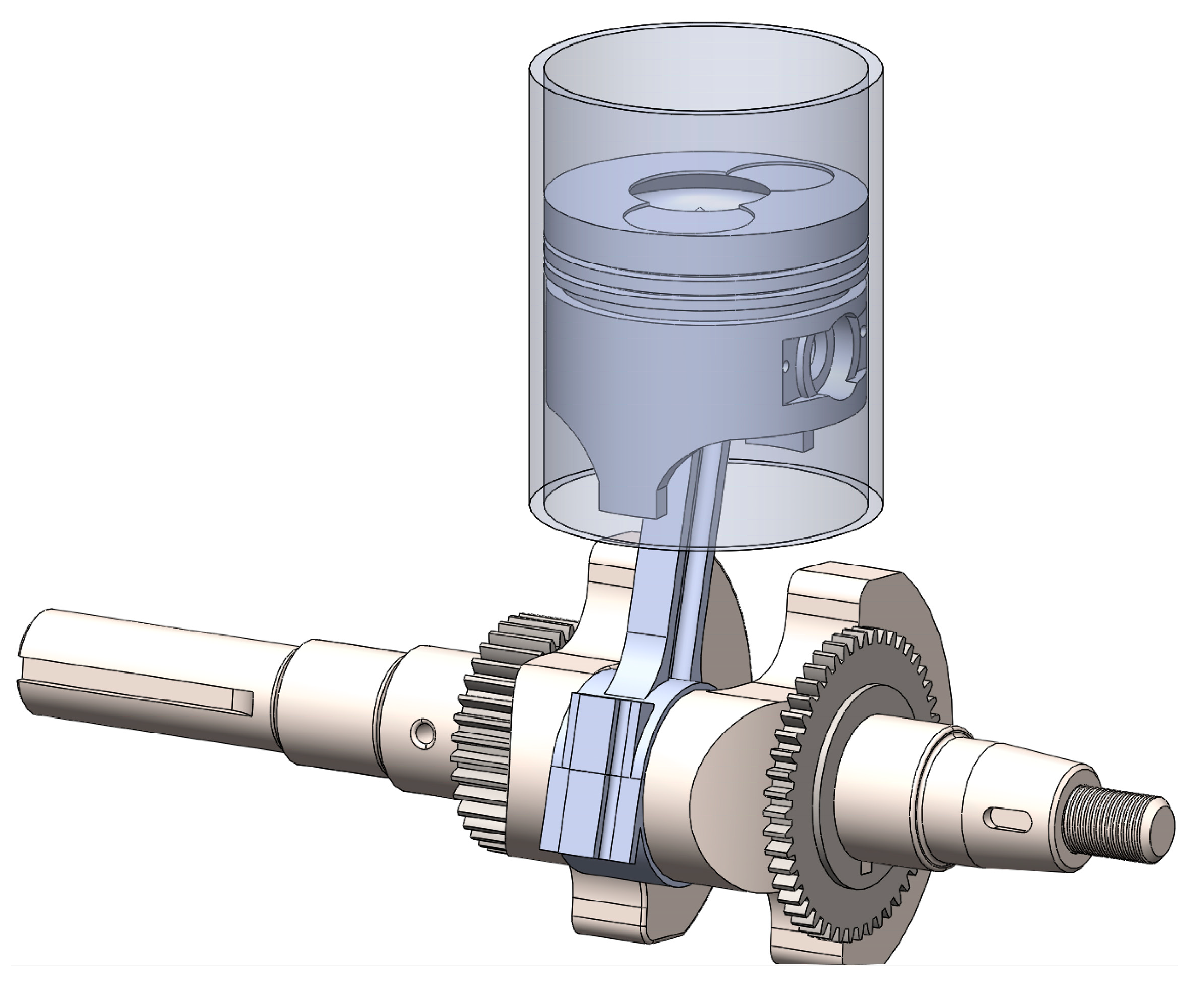
The geometric CAD used for the numerical simulations is formed by the cylinder liner, connecting rod, crankshaft, and piston, as indicated in
Figure 1. The geometric characteristics of the engine CAD are described in
Table 3.
The geometric characteristics of the engine CAD are described in
Table 3.
The computational domain is the boundary by the surface of the cylinder liner, the piston skirt, and the rings’ surface. Additionally, the domain involves the cylinder and the crankcase to represent all the movement of the piston during the stroke. Navier–Stokes’s equations govern the behavior of the numerical simulation. The convergence of the numerical simulations was determined when the residuals reached a value of 10
−4 in the dissipation rate, 10
−4 in the turbulent kinetic energy, and 10
−7 in the energy [
42]. The initial data supplied in the numerical simulation comprise the engine’s rotational speed, the crank angle range of operation, the intake pressure, the cylinder wall temperature, and the inlet temperature during the closing of the intake valve. The characteristics of the contours used in the simulations are shown in
Table 4.
The equations that govern the numerical simulation of the engine, involving the conservation of mass, conservation of momentum, conservation of energy, and turbulence model, are described below.
where
is the fluid density,
is the fluid velocity,
is the stagnation enthalpy,
is the time,
is the pressure,
is the gravitational acceleration,
is the viscous shear stress tensor,
is the radiant heat,
is the heat conduction coefficient,
is the production rate caused by chemical reactions, and
is the mass fraction, respectively.
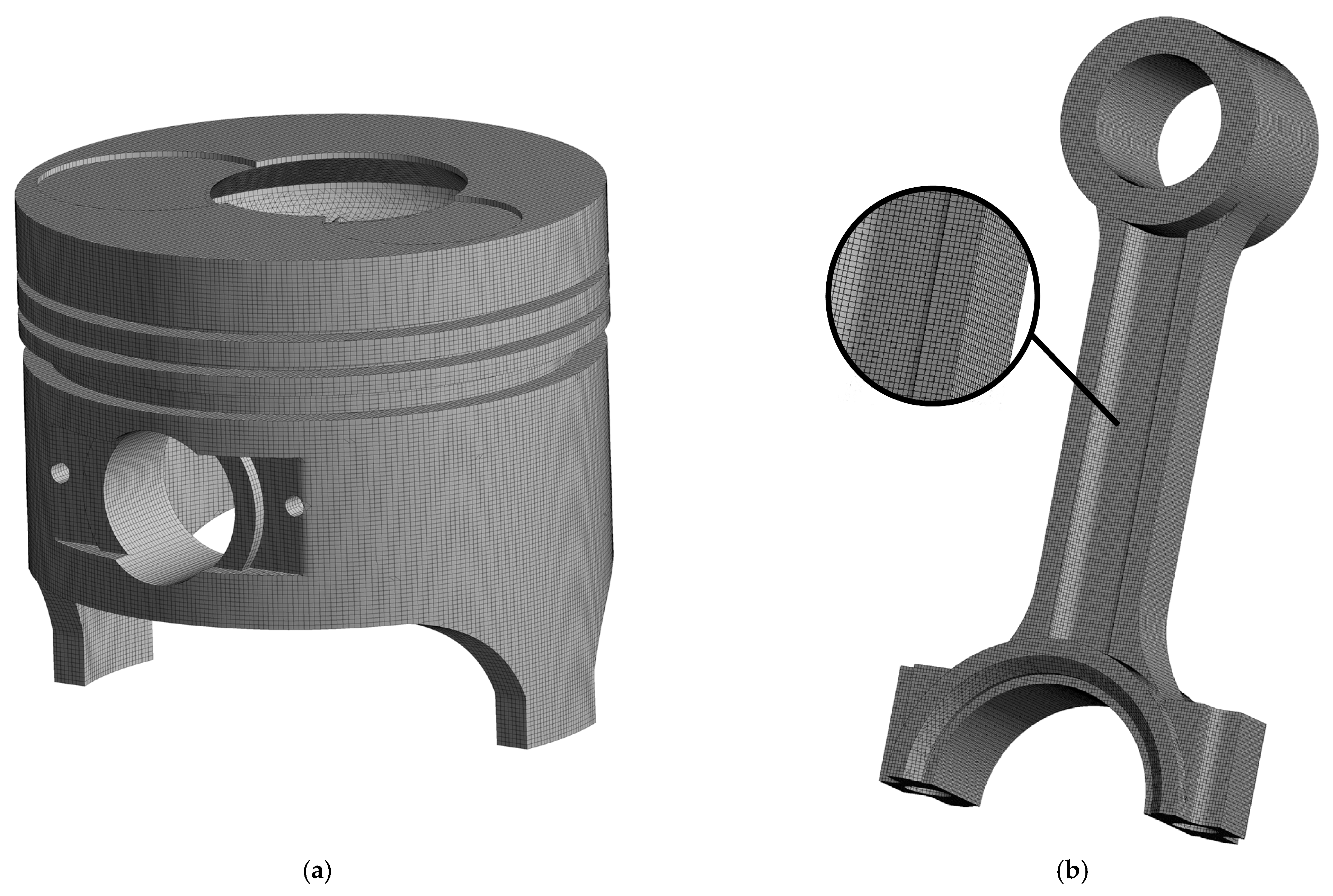
The geometric CAD mesh was generated using SALOME software. The type of 3D mesh used in the present investigation was the hexahedral mesh, with a maximum size of 1 mm.
Figure 2 shows the piston’s meshing and the engine’s connecting rod.
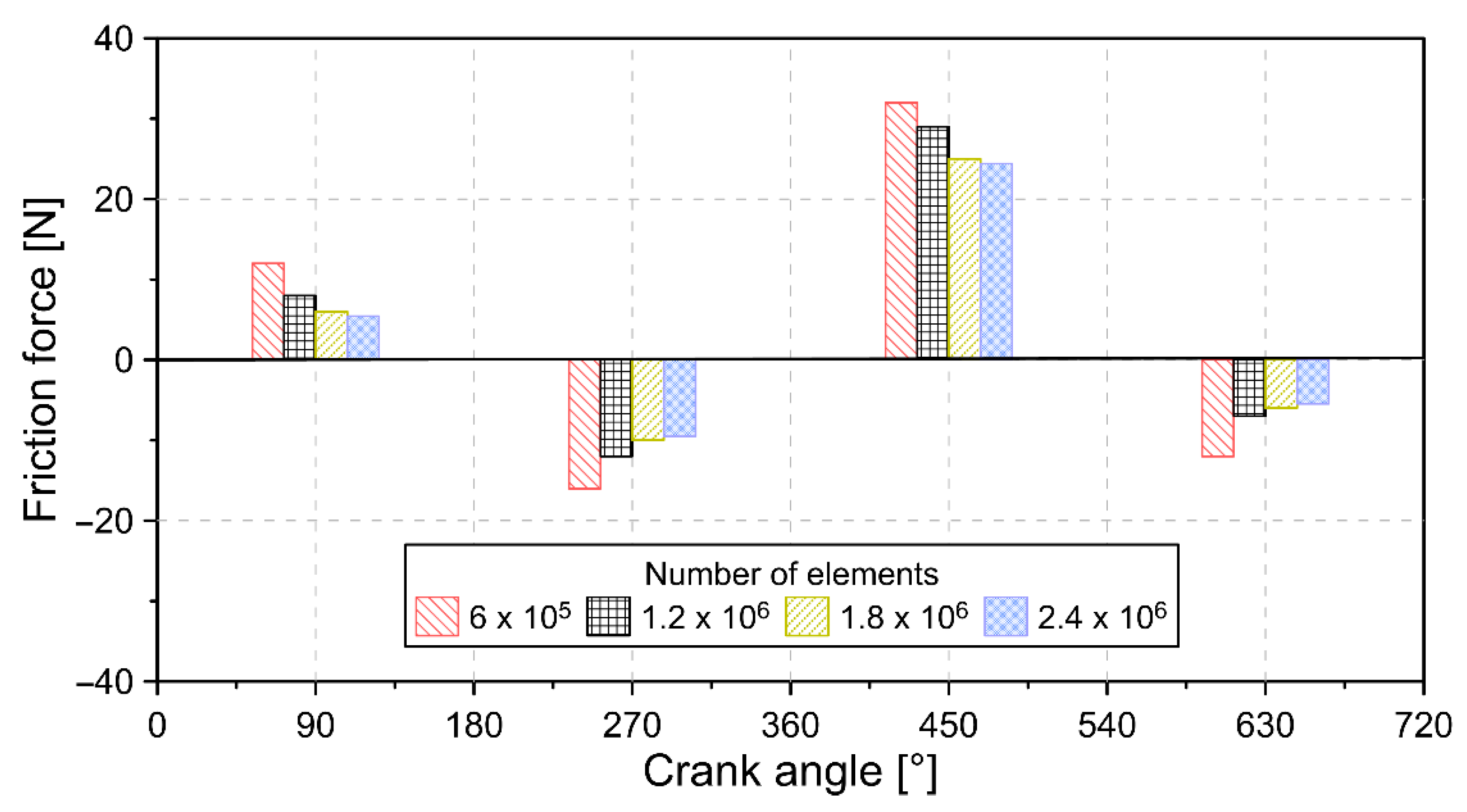
To guarantee the reliability of the mesh, a mesh independence analysis was performed with different numbers of elements. The results obtained are shown in
Figure 3.
Figure 3 shows the friction force throughout the combustion cycle for different numbers of mesh elements. The results show that from a number of elements of
, it is possible to achieve stabilization in the predictions of the simulation. Indeed, the variation was less than 1.5%, compared with the previous number of elements
. Therefore, a mesh with a number of elements of
was selected for the subsequent simulations.
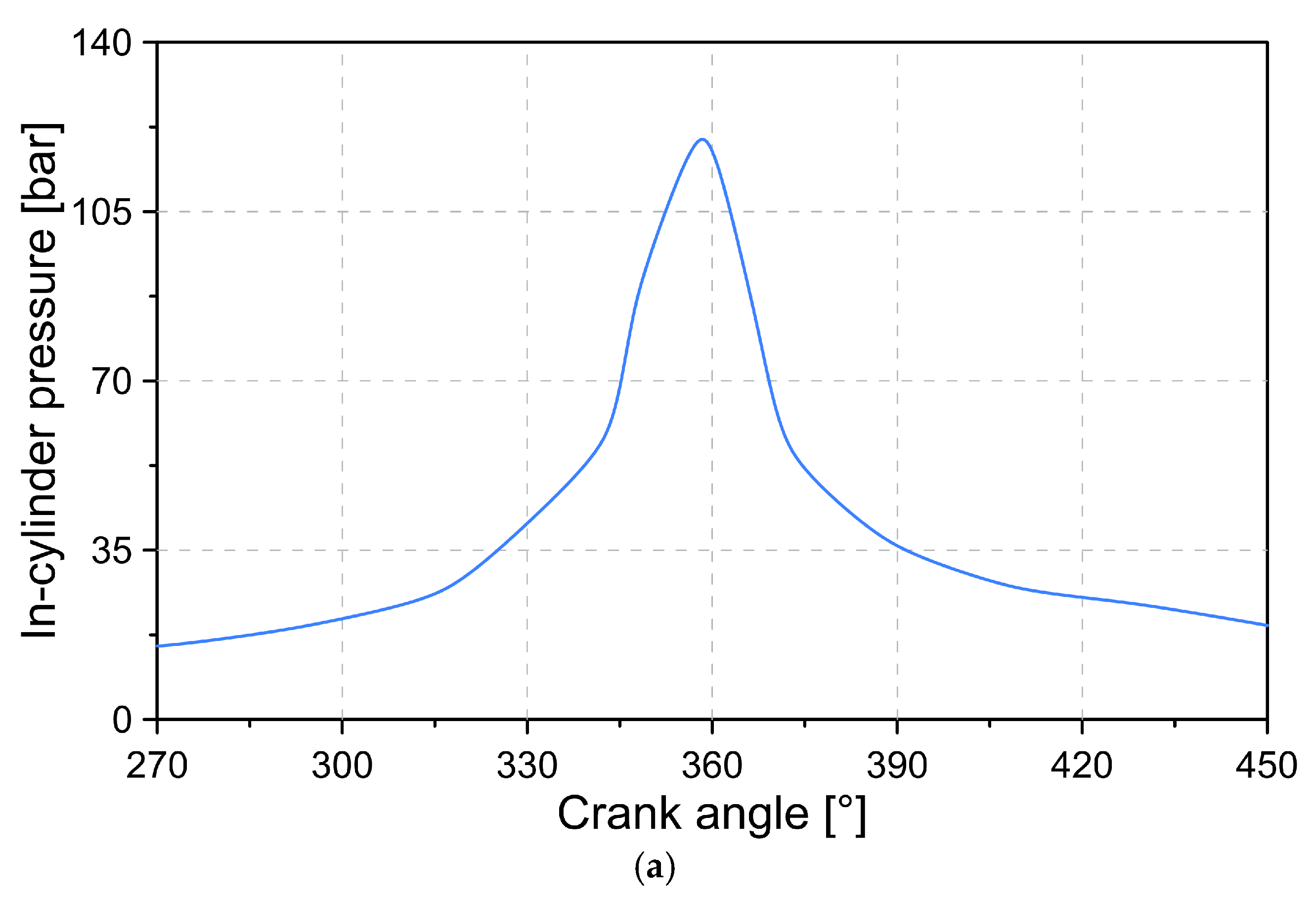
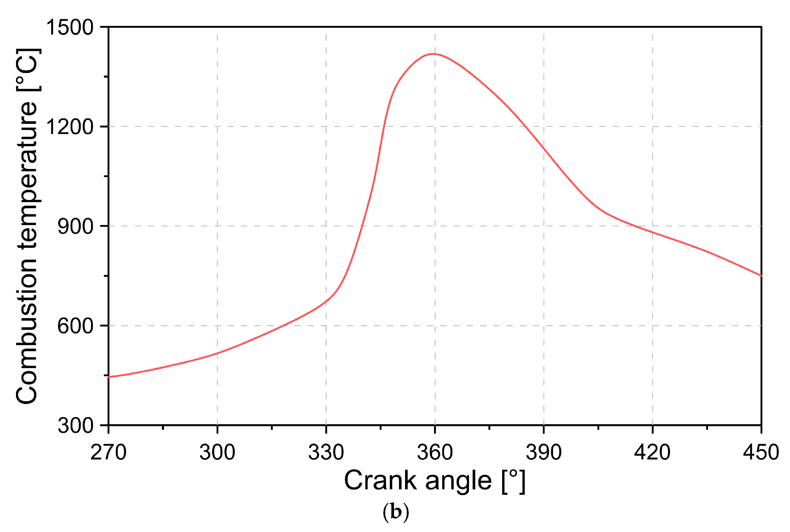
From the results of the numerical simulation, the pressure and temperature curves were obtained throughout the combustion cycle and were used as input data in the tribological model. The data obtained for pressure and temperature are shown in
Figure 4.
To validate the constructed model, experimental tests were carried out to compare the results with the numerical model.
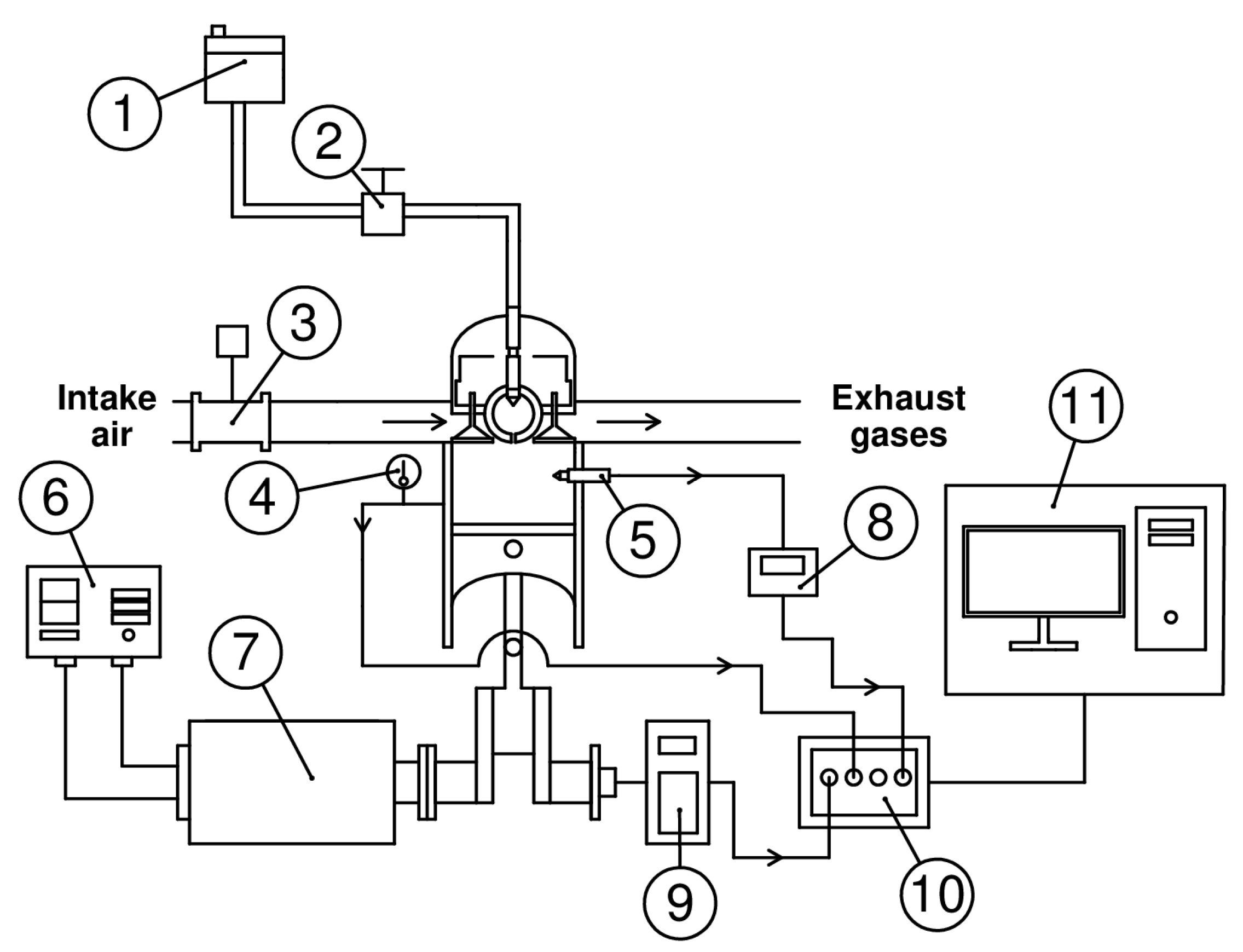
Figure 5 shows the experimental engine test bench.
The test bench engine is connected to a resistive load bank, which is used to control the rotational speed and torque. The measurement of the pressure of the combustion chamber was carried out by means of a piezoelectric sensor (KISTLER type 7063-A, KISTLER, Barcelona, Spain). A crankshaft angle sensor (Beck Arnley 180-0420, Beck/Arnley, Tennessee, EE.UU.) was used to measure the rotational speed. The mass flow of fuel was determined using a gravimetric meter (OHAUS PA313, OHAUS, Cundinamarca, Colombia). K-type thermocouples measured the temperature inside the combustion chamber. A hot-wire type sensor (BOSCH 22,680 7J600, BOSCH, Cundinamarca, Colombia) was used to measure the mass flow of the intake air. The characteristics of the measuring instruments are shown in
Table 5. The methodology used for the development of the research is shown in
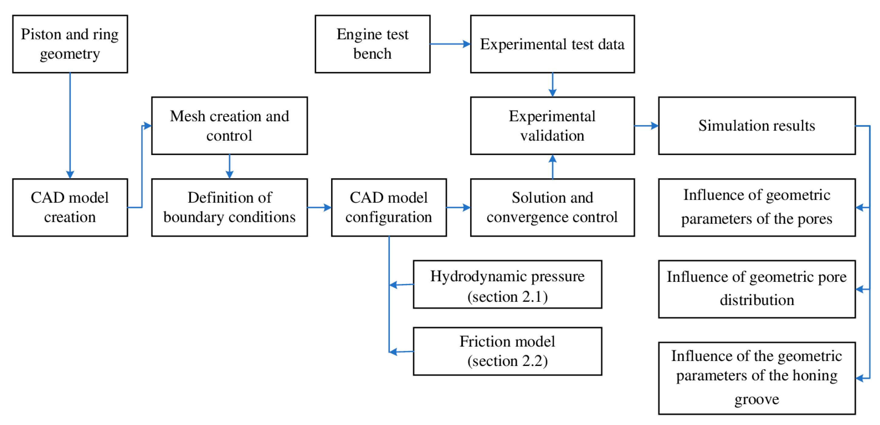
Figure 6.
From the geometric characteristics of the engine, the construction of the CAD of the piston–connecting rod–crankshaft assembly for the CFD model was carried out. The configuration of the CFD model is complemented by the tribological model described in
Section 2. To define the model’s boundary conditions, experimental data on pressure, flow, and temperature conditions in the combustion chamber were collected through the development of experimental tests. The tests were carried out at a rotation speed of 1800 rpm and a torque of 400 Nm. The initial condition of lubrication oil distribution was defined with a thickness of 5 um. This condition refers to the initial coating film on the cylinder liner. Additionally, the contact area between the piston ring face and the cylinder liner was established with a distribution of 90% air and 10% lubricating oil.
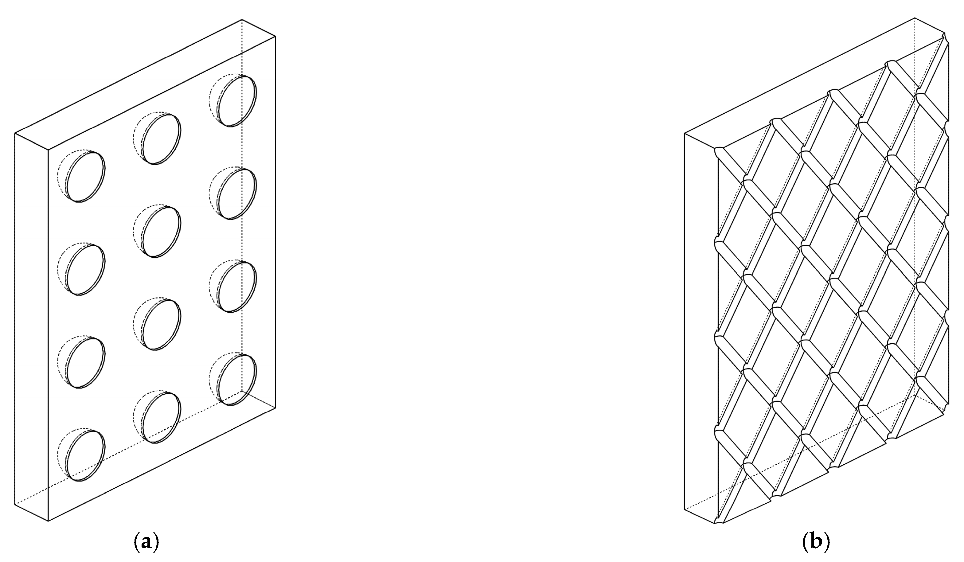
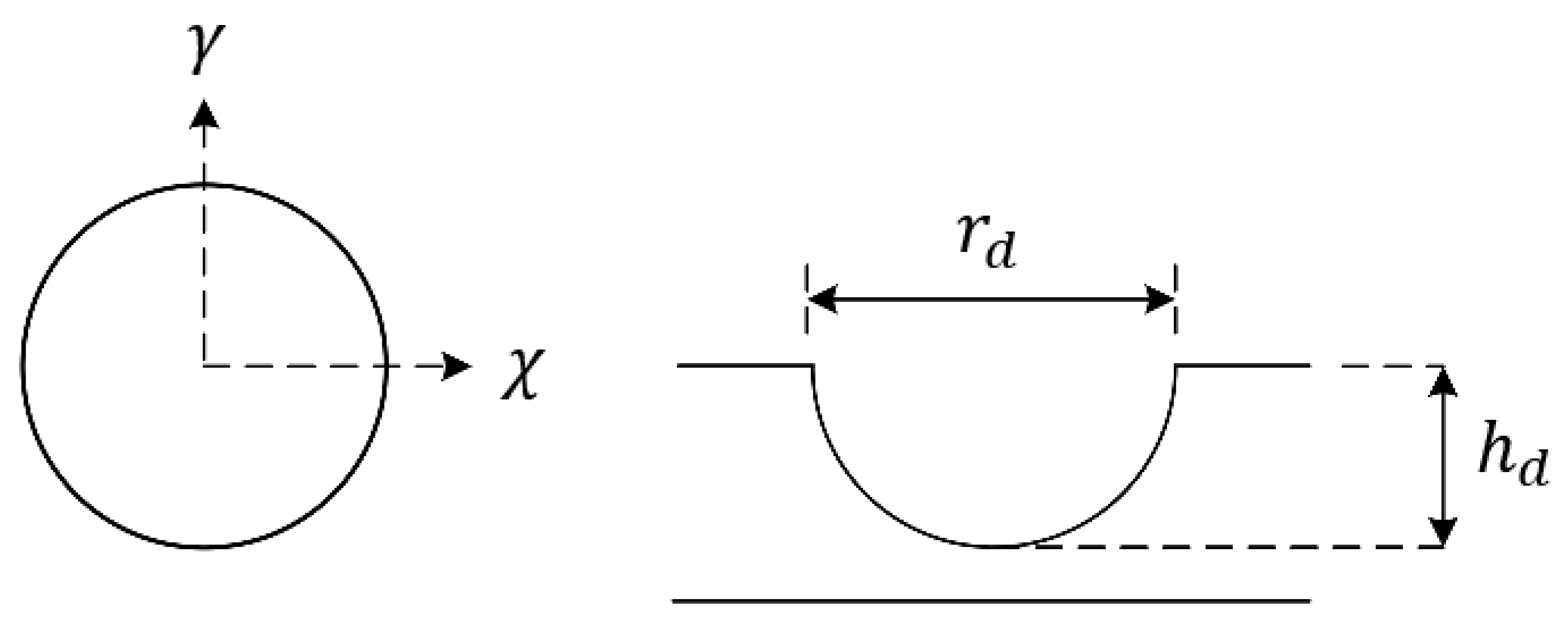
For the development of the study, two types of geometric patterns are evaluated on the cylinder liner. The structure of the patterns studied is shown in
Figure 7.
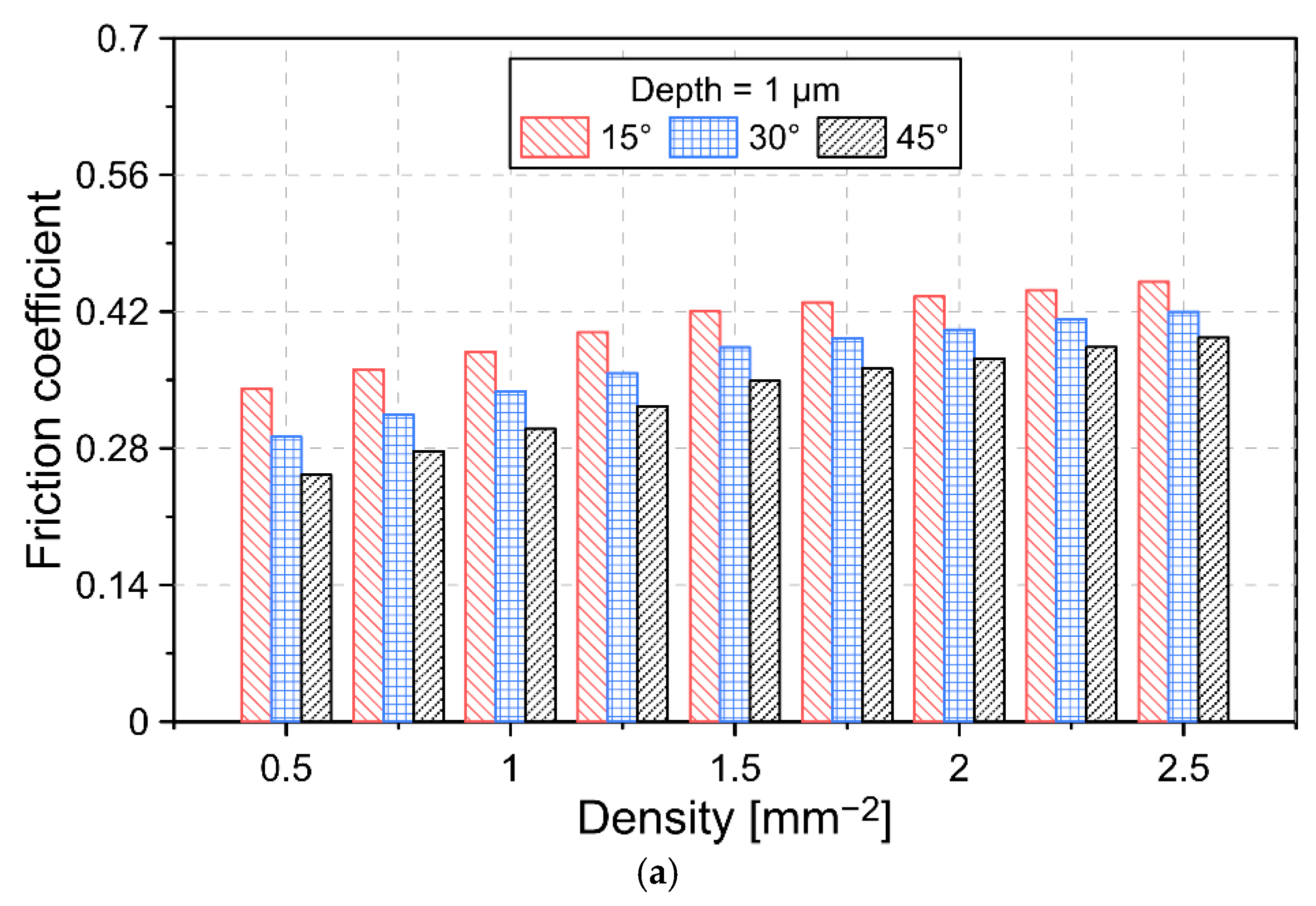
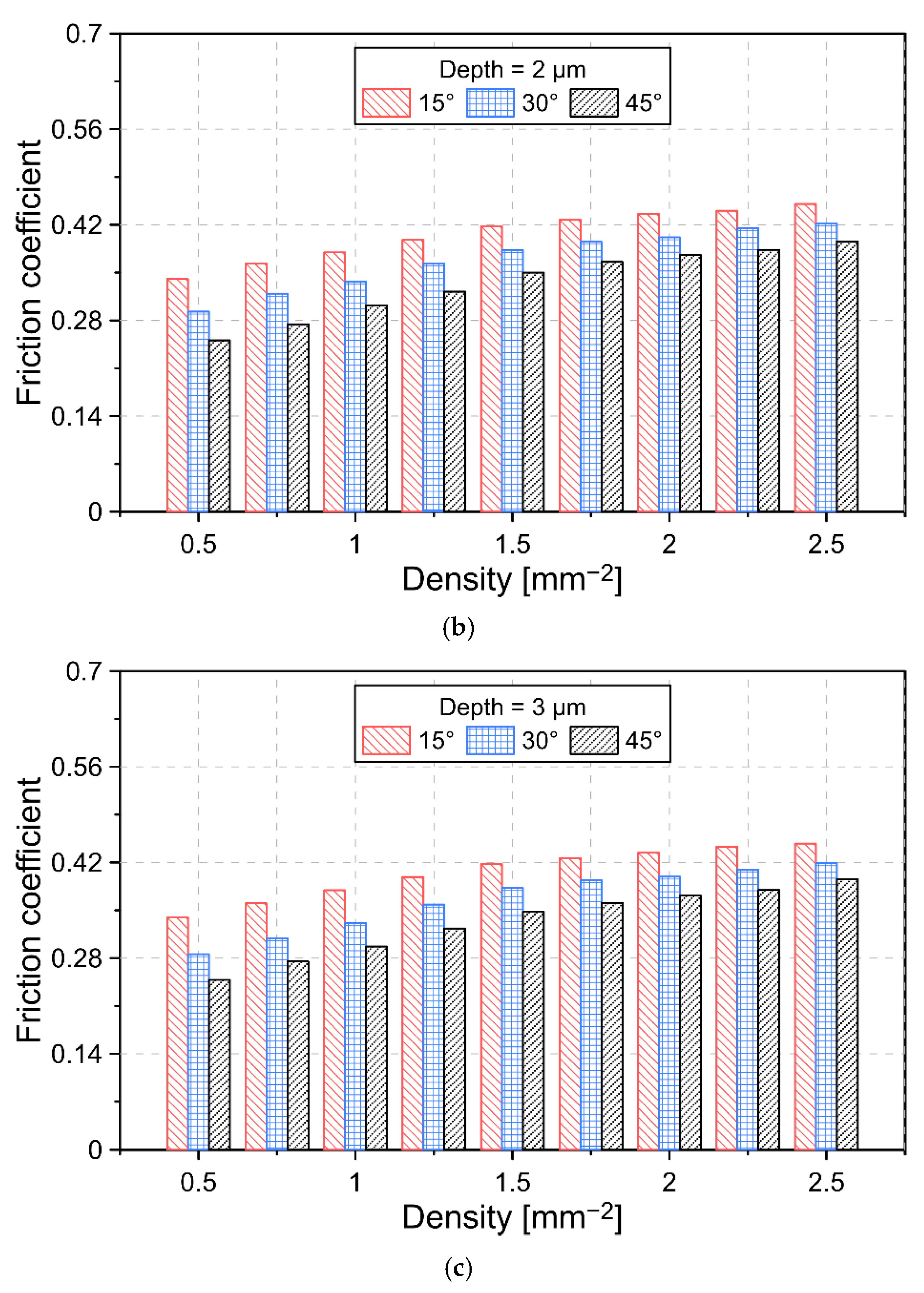
In the case of spherical dimple patterns, two types of dimple density (3% and 6%) and two dimple depths (2 , 3 , and 4 ) were analyzed, respectively. For the honing grooves, the effect of three depths (1 , 2 and 3 ) and a density range between 0.5 and 2.5 mm−2 were analyzed.
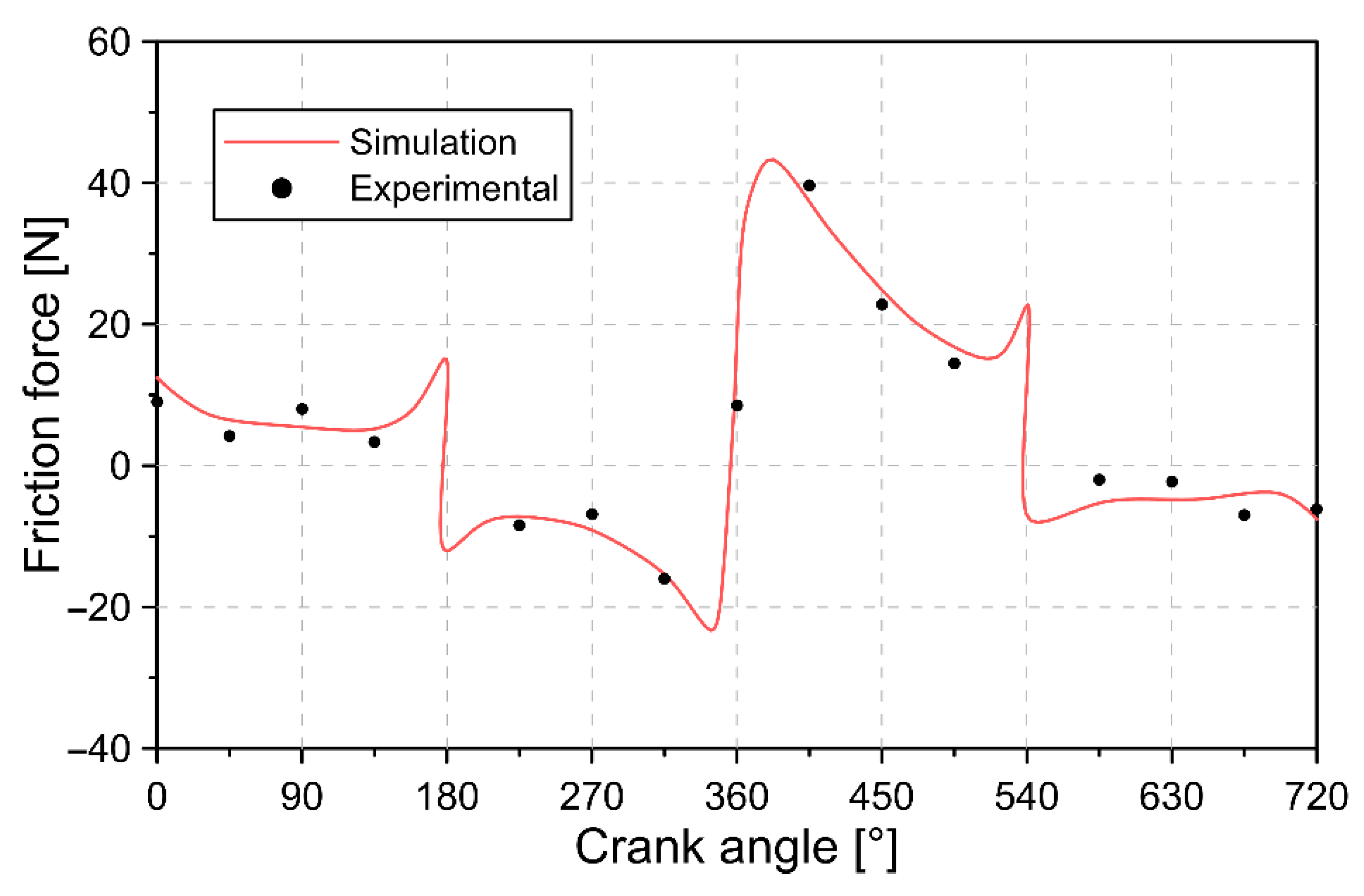
The validation of the numerical model was carried out by comparing the friction force produced in the piston throughout the combustion cycle, obtained through numerical simulation and experimental tests. The friction force was calculated by means of the transverse force on the cylinder liner. For this, a strain gauge sensor was used to calculate the deformation and stress in the cylinder liner. The characteristics of the sensor are indicated in
Table 6.
Since the increase in temperature inside the cylinder produces thermal deformation, a filtering process was carried out. The foregoing was carried out by restoring the signal after reaching stability in the temperature conditions and considering that the engine cylinder has a thermal coefficient of expansion of 24 μstrain/°C [
43]. In this way, it is guaranteed that the measurement made is caused by the mechanical deformation of the cylinder. Finally, the friction force was calculated using Equations (24) and (25) [
44].
where
is the area of the strain gauge sensor,
is the voltage,
is the longitudinal unit strain,
is Young’s modulus of the cylinder liner,
is the experimental friction force, and
is the calibration factor
.
To prepare the inner surface of the cylinder liner, a plateau honing process was first performed before surface texture processing. Subsequently, machining was applied using a computer numerical control (CNC) machine to make the honing groove texture (
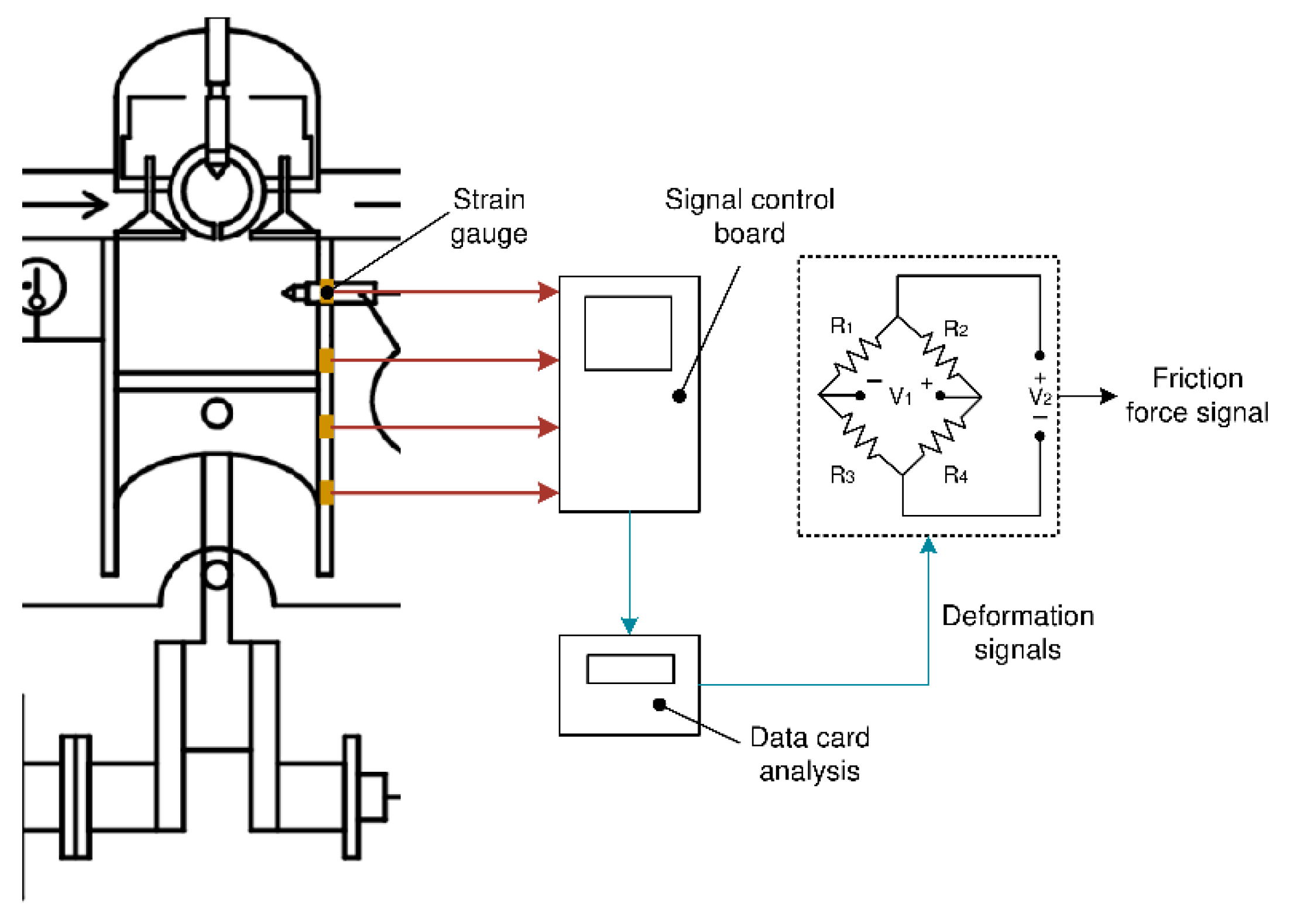
Figure 7), with a depth of 3µm and an inclination angle of 45°, respectively. The experimental setup for friction force signal processing is indicated in
Figure 8.
5. Conclusions
In the present investigation, an analysis of the effects of dimples and honing grooves on the cylinder liner on the tribological characteristics of an internal combustion engine was carried out. For the study, a tribological model was used in order to determine the hydrodynamic behavior and the friction forces between the cylinder liner and piston. Additionally, the construction of a CFD model was carried out to describe the real dynamics of the piston. Numerical model validation was performed by comparing simulated results and experimental data. In general, a close similarity between the model predictions and the real behavior was obtained, obtaining an average relative error of 14%.
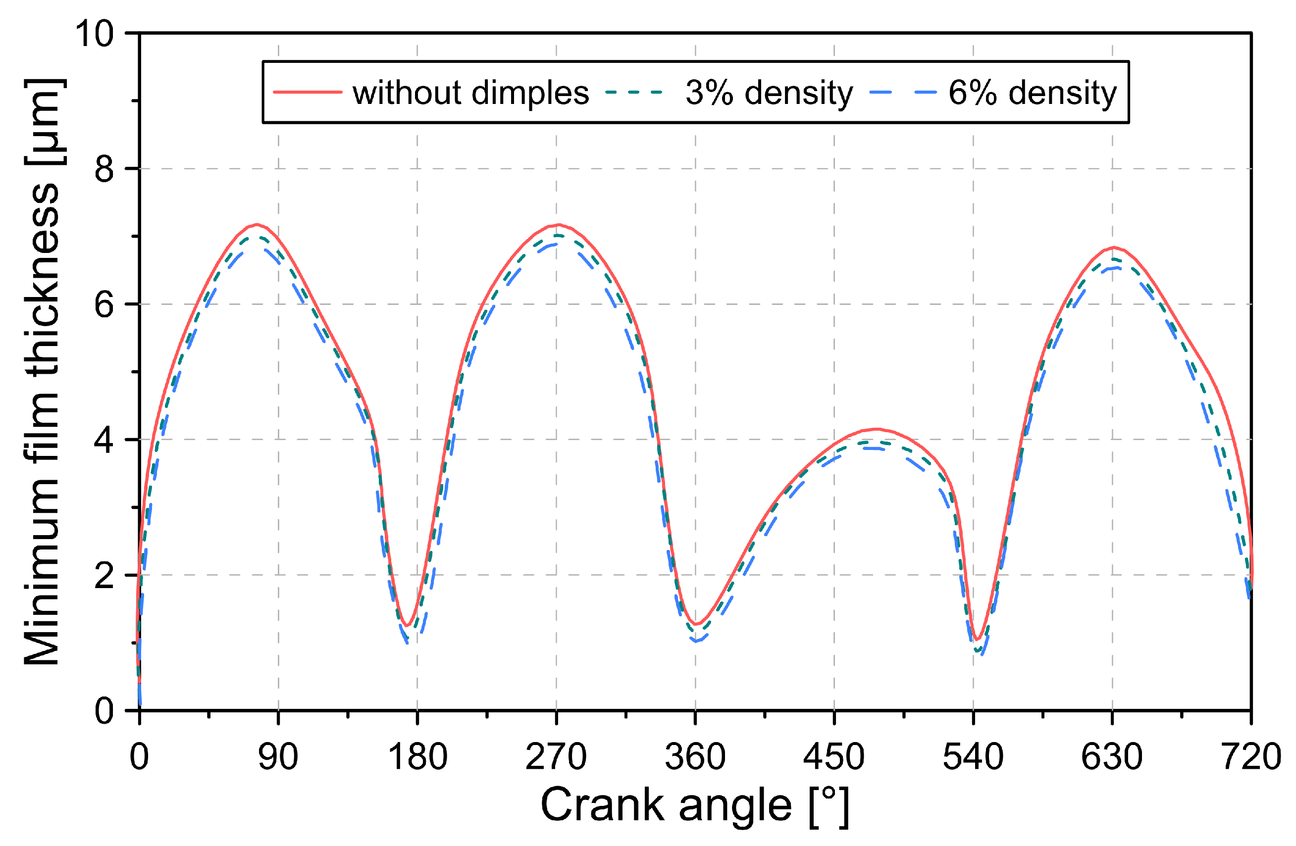
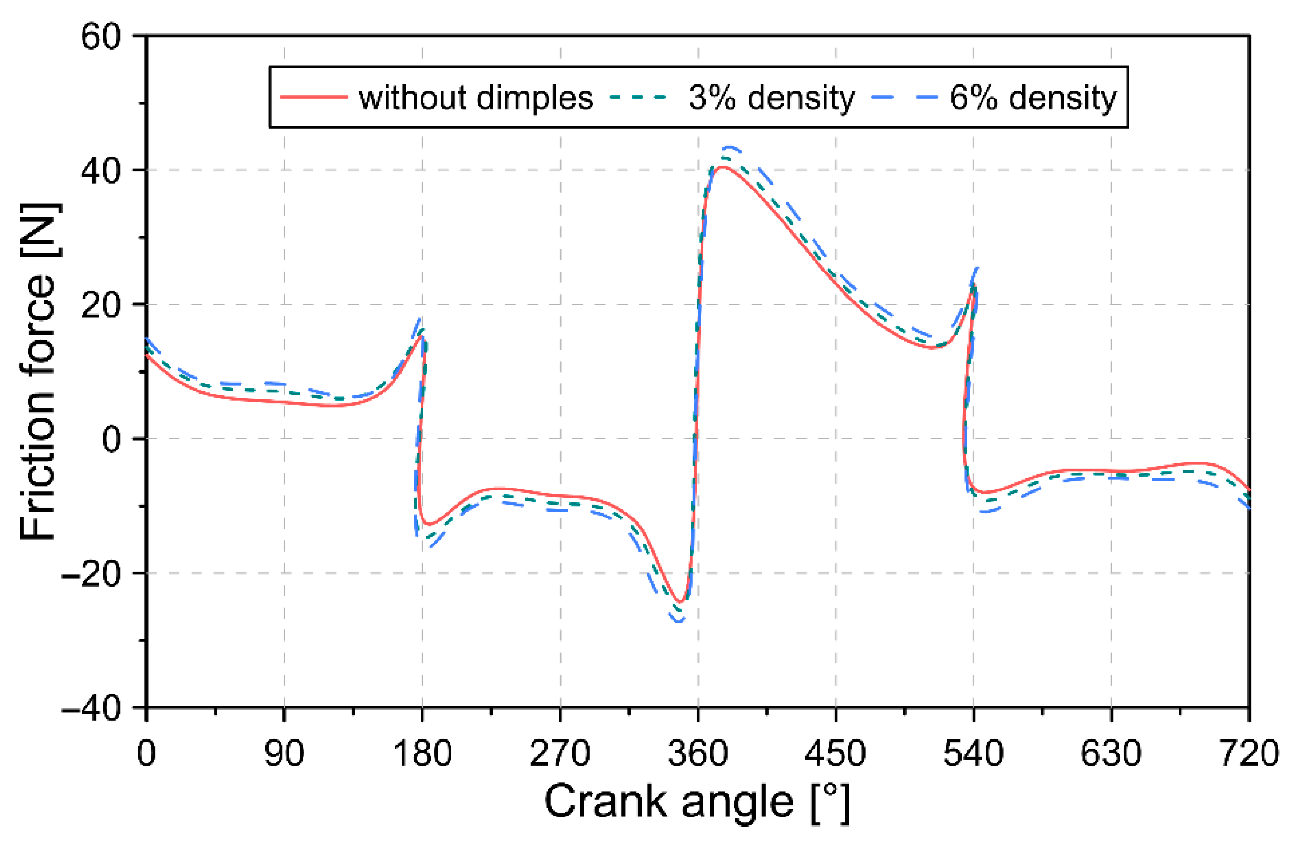
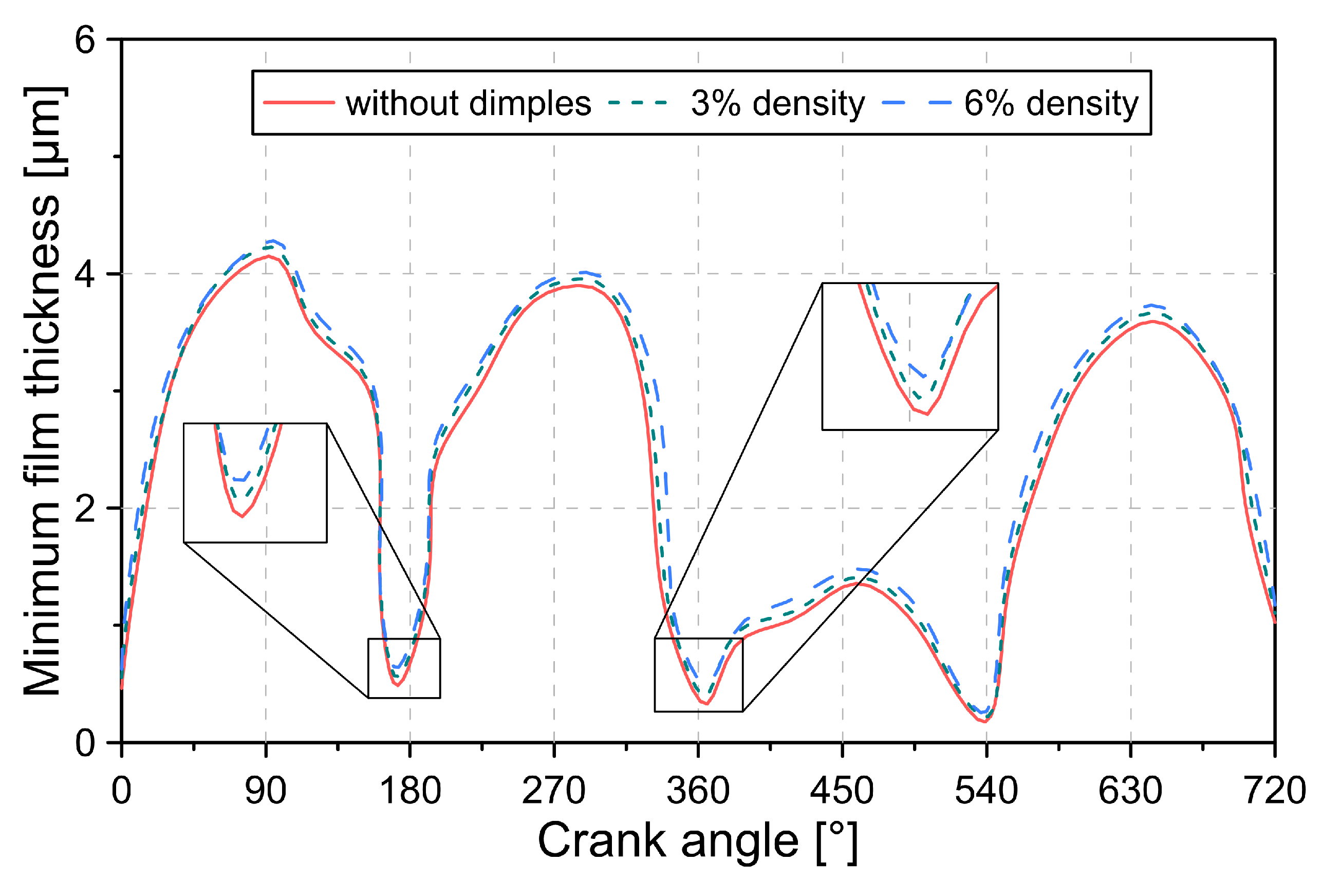
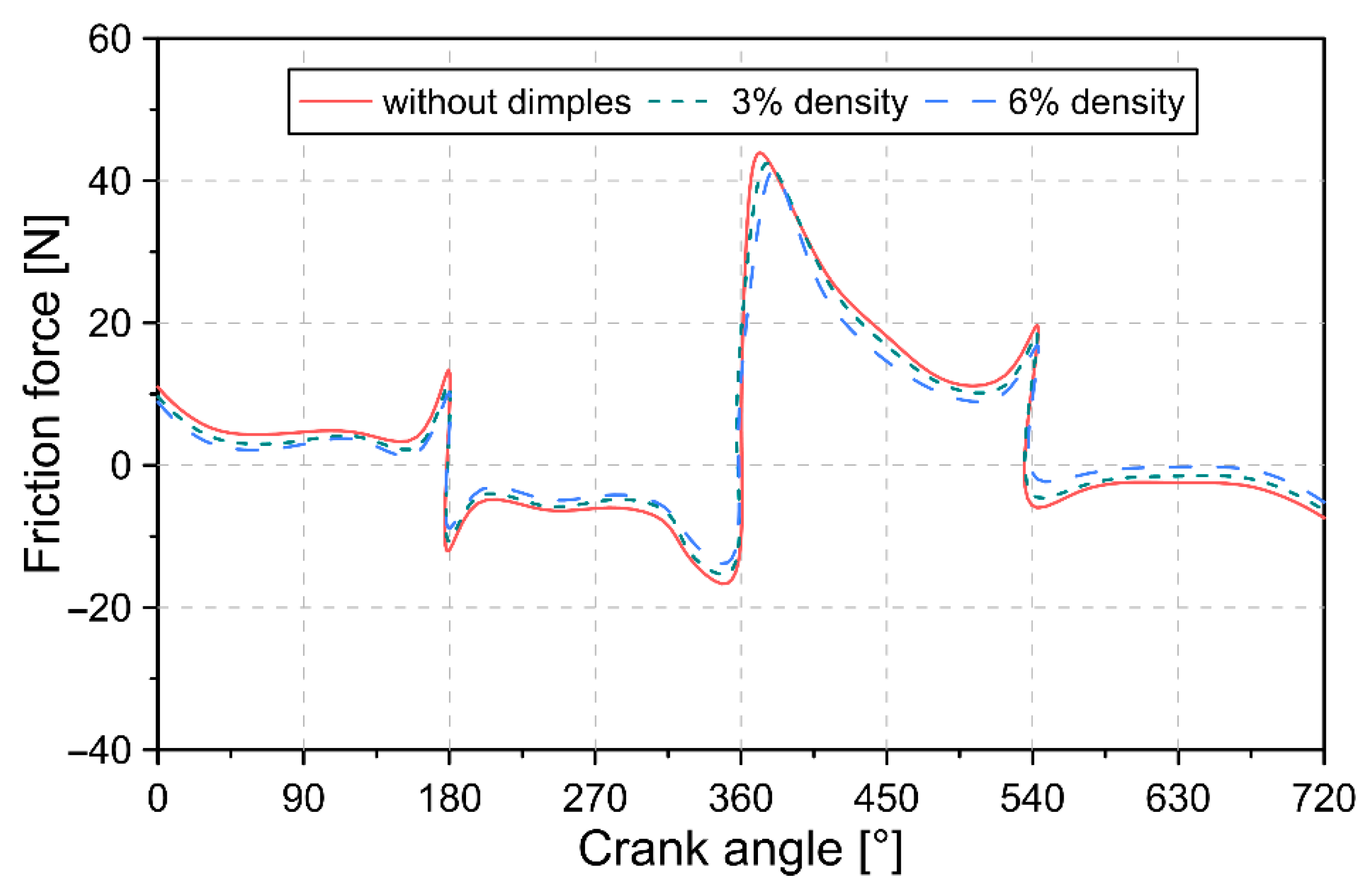
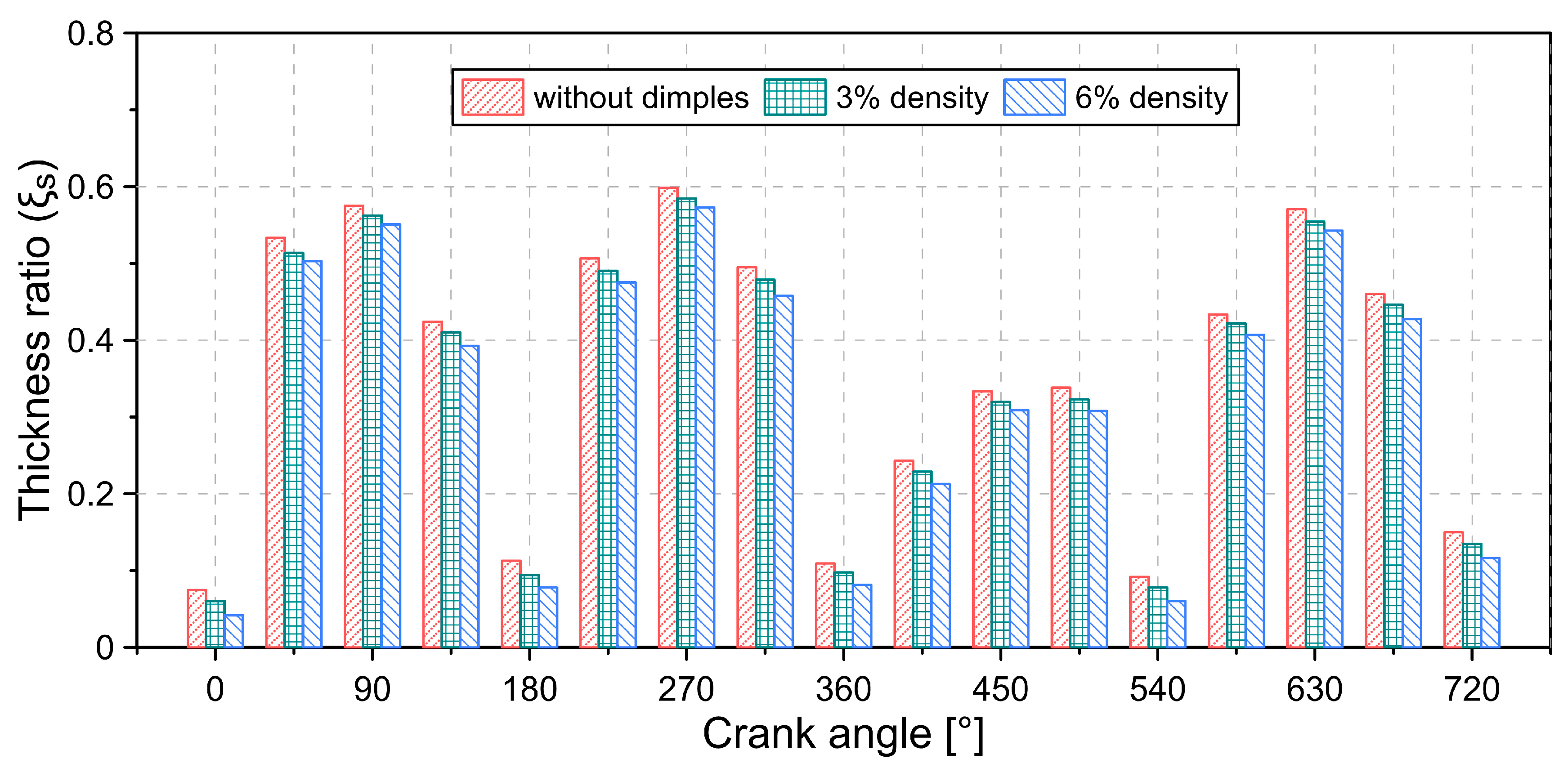
From the results, it was possible to conclude that the increase in dimple density has a positive impact on the increase in the lubricant film thickness and reduction in the friction force between the piston rings and the cylinder liner in starved lubrication conditions. In general, a 3% increase in dimple density led to a 3.79% increase in minimum lubrication film thickness and a 2.76% decrease in friction force. This allows reducing energy losses and wear of engine components. However, in flooded lubrication conditions, the presence of dimples in the cylinder liner does not allow a reduction in frictional force to be achieved. Despite the above, engines operate with starved lubrication during much of the combustion cycle.
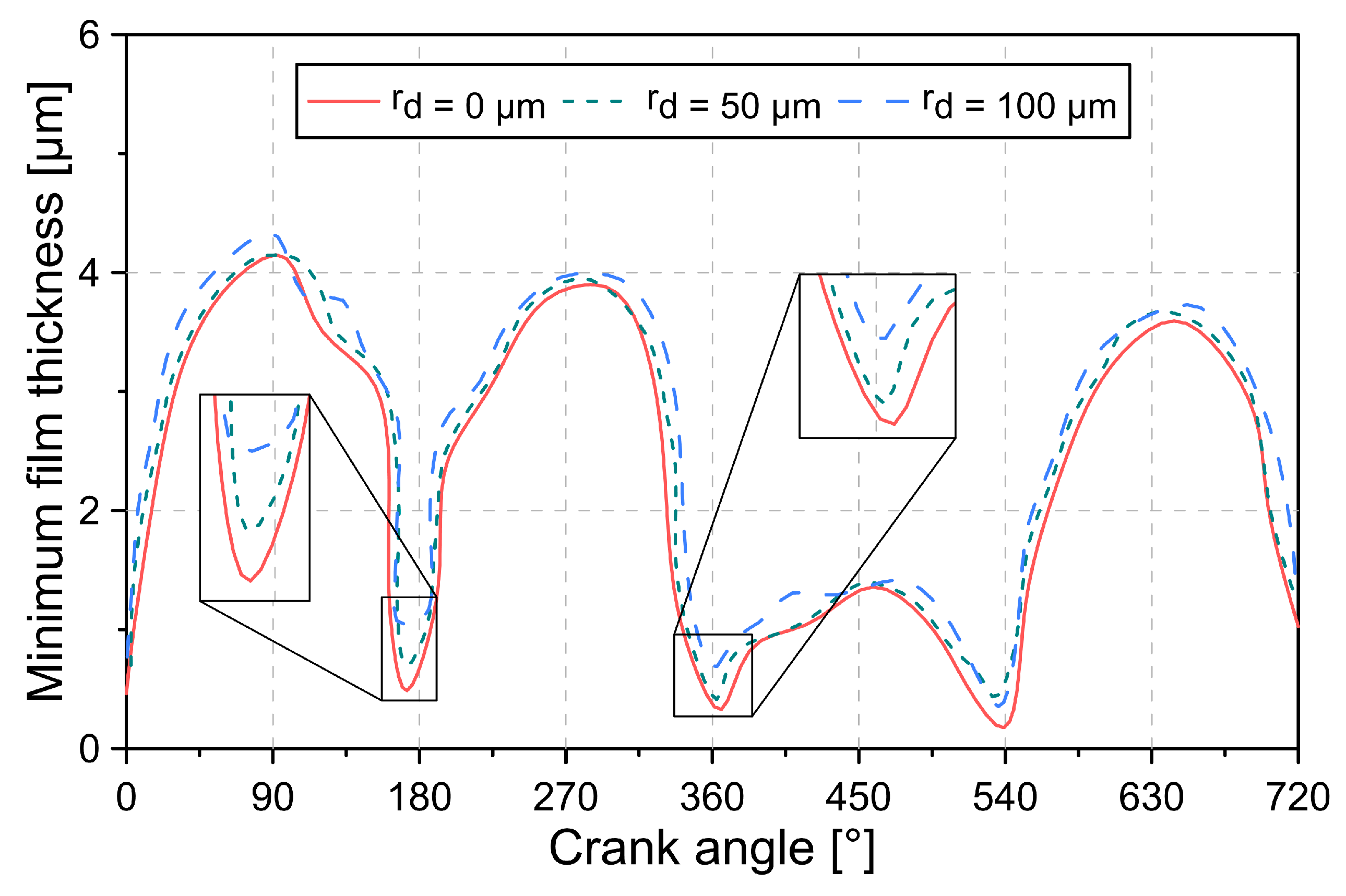
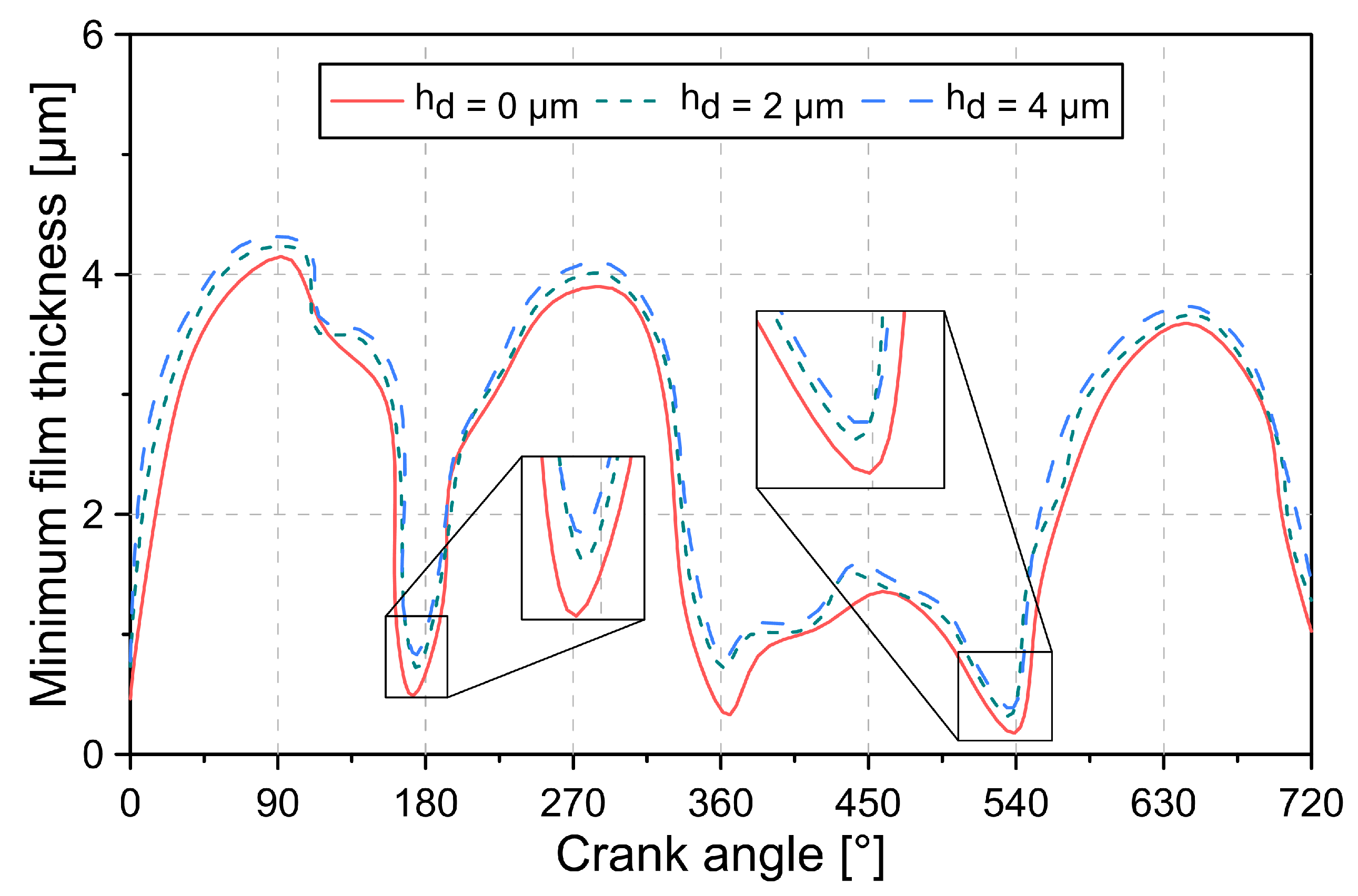
The radius and depth of the dimple affect the tribological characteristics of the engine. The results show that the increase in the previous geometric parameters allows for increasing the minimum thickness of the lubrication film. In general, it was concluded that doubling the radius and depth of the dimple produced an increase of 3.86% and 1.91% in the minimum thickness of the lubrication film.
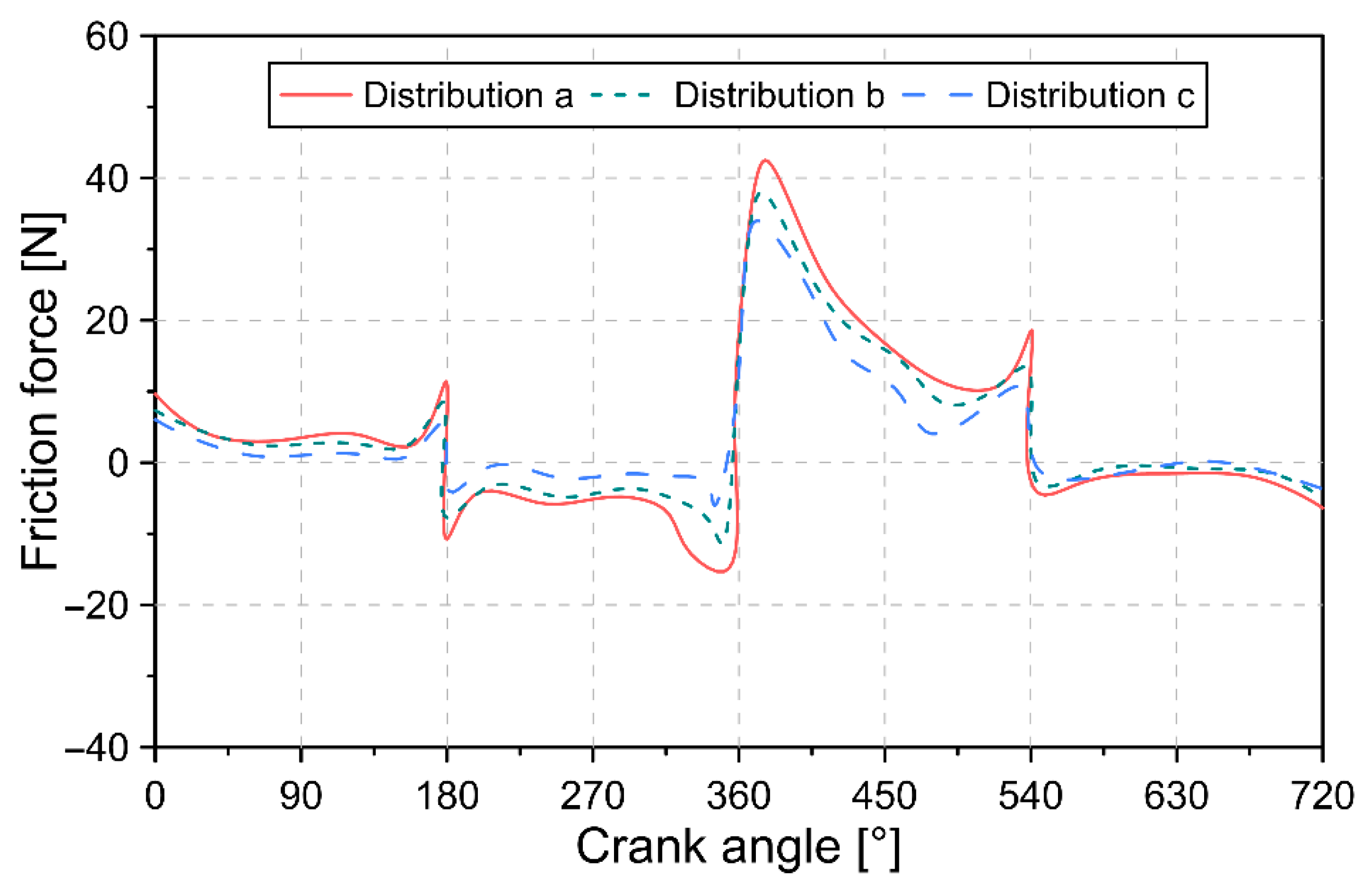
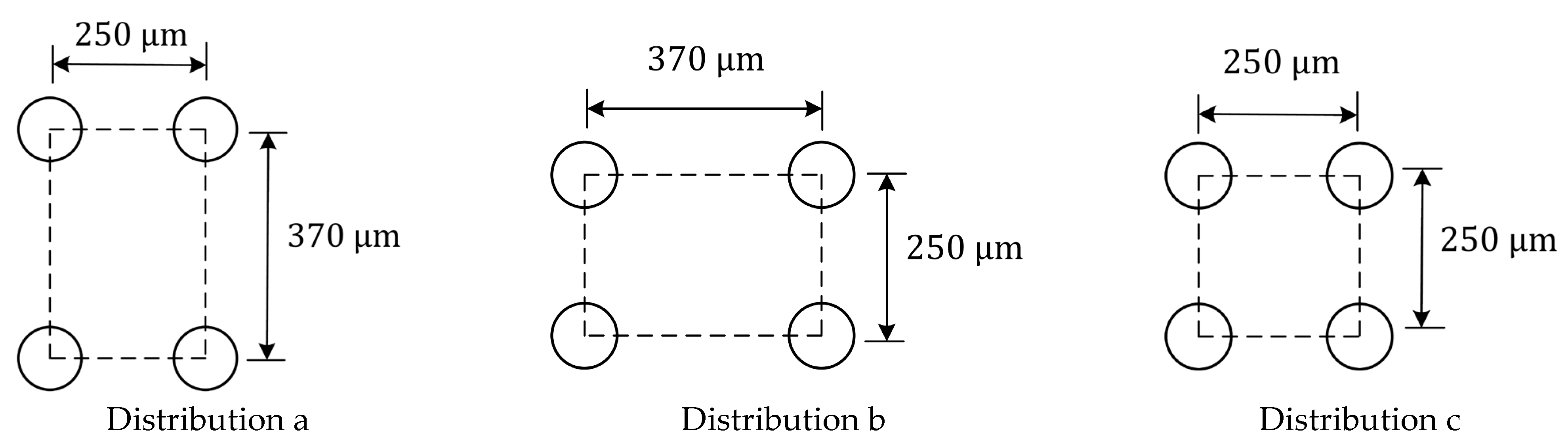
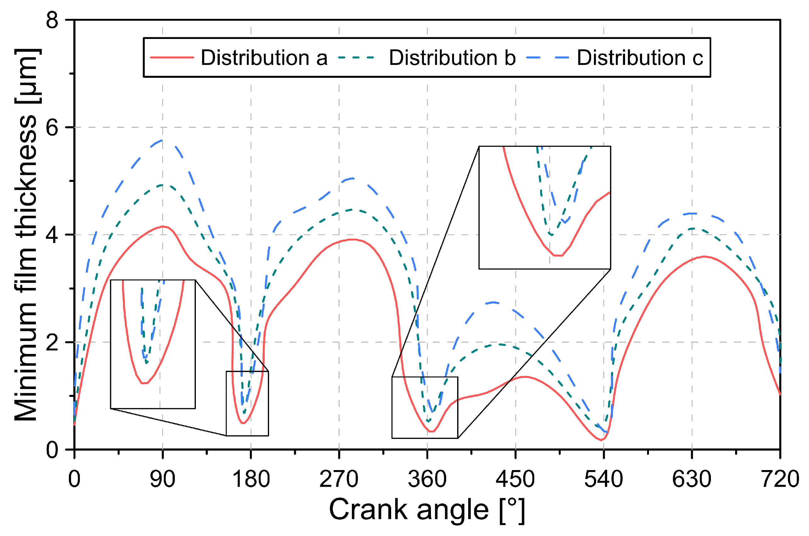
The most suitable distribution of the dimples on the surface of the cylinder liner corresponds to a square array (distribution c) since this allows a significant increase in the minimum thickness of the lubrication film, especially in the middle position of the piston stroke.
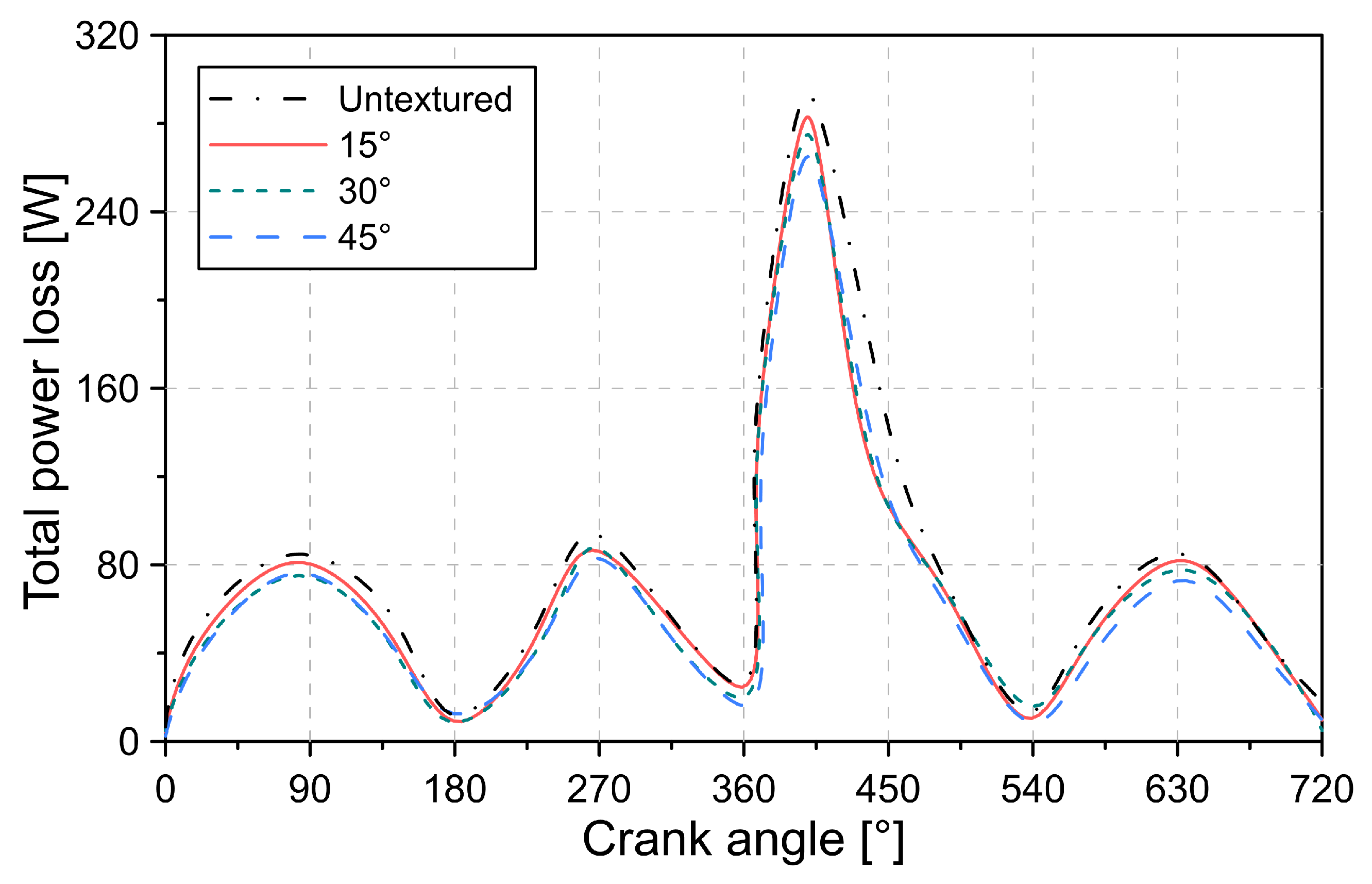
The analysis of the geometric parameters of the honing groove showed that the honing groove density and honing angle strongly influence the coefficient of friction. On average, a 15° increase in honing angle caused a 14.24% reduction in the coefficient of friction. However, excessively increasing honing groove density results in higher engine friction.
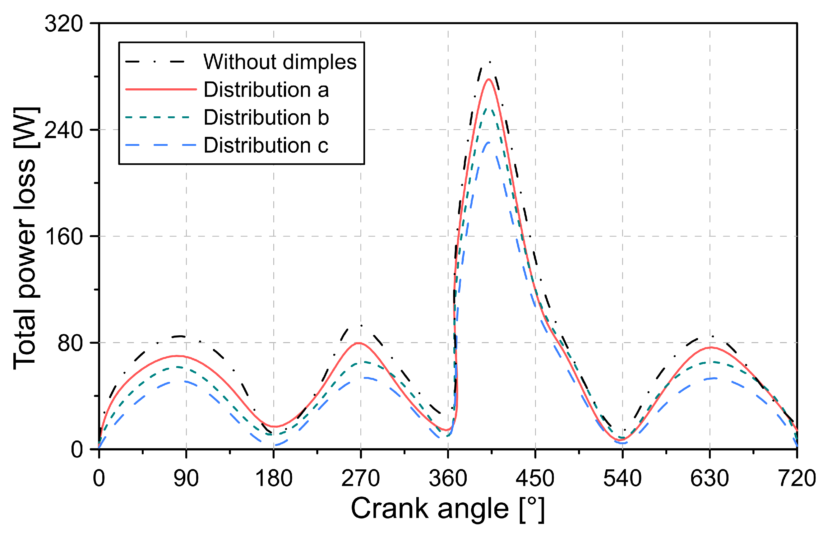
In general, the application of dimples and honing grooves in the cylinder liner are promising alternatives to reduce energy losses and minimize wear of engine components. Although both types of cylinder liner textures reduced power losses during the combustion cycle, a maximum decrease of 21.4% and 9.6% was observed with the dimples and honing grooves texture. However, it is necessary to build a regression model that allows finding the best geometric characteristics of both textures to demonstrate, which is the most appropriate. Future research will focus on this problem.


