1. Introduction
Due to today’s stringent emission control regulations, manufacturers and researchers have focused efforts on minimizing fuel consumption, improving performance, and reducing greenhouse gas emissions caused by internal combustion engines (ICE) [
1,
2,
3]. The above aims to mitigate the environmental impact and avoid the accelerated consumption of fossil fuel reserves. Research in the literature indicates that approximately 50–60% of the energy contained in fuel is lost due to thermal inefficiencies [
4]. In addition, the friction between the internal components can produce losses between 4 and 20% depending on the load conditions of the engine [
5,
6]. Since 99.8% of the demand in the transport sector comes from hydrocarbon fueled engines, it is necessary to implement alternatives to reduce the sources of energy losses in engine components.
One of the main energy-loss sources in ICEs is the interaction between the piston rings and the cylinder liner. The main objective of the compression rings is to form a hermetic seal between the cylinder liner and the piston to mitigate the leakage of combustion gases. This makes it possible to avoid pressure loss inside the combustion chamber. However, this type of sealing contributes significantly to energy losses due to frictional conditions between the piston rings and the cylinder liner. Additionally, the flexibility and thinness of the compression ring affects the sealing ability of the chamber. The above conditions lead to an increase in harmful gases from the engine [
7] due to the unburned fuel trapped between the piston rings, promoting the formation of hydrocarbon emissions [
8]. Studies indicate that between 3 and 5% of the total ICE losses are a consequence of the interaction between the piston ring and the cylinder liner [
9]. In the case of combustion gas leaks, an energy loss of between 2 and 7% is attributed. Therefore, the dynamic behavior and the sealing capacity of the compression rings are aspects that can be intervened to achieve a significant improvement in the energy efficiency of the ICE [
10].
Over the years, different strategies have been developed to increase the efficiency of ICEs. Among which are improvements in combustion systems, engine tribology, electronic control, and detection algorithms [
11,
12,
13,
14]. Additionally, technologies such as exhaust gas recirculation [
15], turbocharging [
16], direct injection, HCCI (homogeneous charge compression ignition) engines [
17], alternative biofuels [
18], ratios of variable compression [
19,
20,
21], and cylinder deactivation (CDA) [
21]. The latter has received high interest in its application for gasoline engines. Since cylinder deactivation allows for high emission reductions and energy savings [
8].
The CDA consists of the deactivation of some cylinders, which causes the rest of the active cylinders to require a higher load condition to maintain the brake mean effective pressure (BMEP). This causes an increase in intake manifold pressure and a reduction in pumping losses in gasoline engines [
22]. Studies indicate that the application of CDA can lead to a 17–25% reduction in brake specific fuel consumption (BSFC) [
23]. This reduction is mainly attributed to the decrease in pumping losses.
Another of the main influencing factors in fuel consumption is the mechanical losses of the engine. Depending on the load condition, about 20% of the fuel energy is used to overcome mechanical actuation and friction [
24]. After cylinder deactivation, pressure and temperature variables are factors that have a notorious impact on the viscosity and thickness of the lubricating oil. Bewsher et al. [
25] indicated that total friction losses increased by 9.53% due to cylinder deactivation. Therefore, it is necessary to consider the influence of the CDA on the tribological characteristics of the engine. In general, the tribological behavior of the conjunction of the piston rings and the cylinder liner are key to reducing friction losses. Additionally, the dynamics of the ring body affects the leakage gases and the distribution of oil in the piston ring pack [
26].
The investigations described previously show the importance of the tribological conditions at the conjunction of the piston rings and the cylinder liner on power losses and engine emissions. Due to the above, this research aims to evaluate the effect of technologies such as cylinder deactivation on the tribological characteristics of a compression ignition engine. The study consists of evaluating the conditions of the combustion chamber, analyzing the friction force, loss power, combustion gas leakage, and CO, HC, and NO emissions.
2. Numerical Model
2.1. Tribological Model
To determine the hydrodynamic pressure between the conjunction of the piston rings and the cylinder liner, the modification of the Reynolds equation proposed by Guo et al. [
27] was used, as described in Equation (1).
where
is the viscosity of the lubricant,
is the thickness of the lubricant,
is the film pressure of the lubricating oil,
is the piston velocity,
and
are the pressure flow factors,
is the composite roughness,
is a contact factor, and
is the shear flow factor. The pressure flow factors
were calculated using Equation (2) [
28].
Since the conditions of pressure and temperature affect the properties of the oil, the relationship proposed by Dowson and Higginson was used to determine the density of the lubricating oil, as shown in Equation (3) [
29].
The subscript refers to environmental conditions, and is the coefficient of thermal expansion.
In the case of the viscosity of the lubricating oil, the model proposed by Houpert was used, which is described in Equation (4) [
30].
where
is the lubricant piezo-viscosity index and
is the thermo-viscosity index, respectively. The
and
indices were determined by Equations (5) and (6).
where
is the thermo-viscosity coefficient and
is the atmospheric piezo-viscosity coefficient, respectively.
and
are model constants, which were calculated using Equations (7) and (8).
The thickness of the lubricating oil film was calculated by means of Equation (9).
where
is the minimum oil film thickness and
is the thickness of the oil due to the geometric profile of the piston ring, respectively. For the calculation of
Equation (10) was used [
31].
where
is the piston ring axial width and
is the crown height, respectively.
2.2. Friction Force Model
The conjunction of the piston ring and the cylinder liner cause the presence of two types of friction forces, which are a consequence of the viscosity of the lubrication film and the interaction between the asperities present on the surface of the piston rings and the cylinder liner. To determine the viscous friction force
, Equation (11) was used.
where
is the viscous shear stress,
is the real area of contact area and
is the apparent contact area, respectively. To determine
Equation (12) was used [
32].
The real contact area
was calculated by means of the Equation (13).
where
is the asperity distribution per unit contact area,
is the average asperity tip radius of curvature, and
is the statistical function of the Stribeck lubricant film ratio
. The statistical function
was determined by Equation (14) [
33].
In the case of the asperity friction force
, this was calculated by means of the Equation (15) [
34].
where
is the limiting Eyring shear stress,
is the coefficient of asperity shear strength, and
is the asperity contact load. To determine the asperity contact load
, the model proposed by Greenwood and Tripp was used, as shown in Equation (16) [
34].
The equivalent Young’s modulus of elasticity
was calculated from the Equation (17).
where
and
are the modulus of elasticity of the cylinder liner and piston ring, respectively.
and
are the Poisson’s ratio of the cylinder liner and piston ring, respectively.
is a statistical function of lubricant film ratio approximated by a fifth order polynomial as [
35]:
2.3. Gas Blow-by Model
The mass flow of combustion gases through the piston rings was calculated assuming an isentropic flow condition through an equivalent orifice, as shown in Equation (19) [
36].
where
is the coefficient of discharge,
is the orifice upstream temperature,
is the compressibility factor,
is the ring end-gap area, and
is the gas constant, respectively.
The compressibility factor
was calculated from Equation (20) [
36].
where
and
are the downstream pressure and upstream pressure, respectively.
is the discharge coefficient, calculated from Equation (21).
2.4. Deformation Model
The equations used to describe the deformation of the piston rings are given below:
where
is the piston ring material density,
is the cross-sectional area of the ring,
is the second area moment of inertia,
is the ring radius of curvature, and
is the angular position along the ring circumference,
and
are the radial force and tangential force acting on the piston ring, respectively.
3. Numerical Procedure
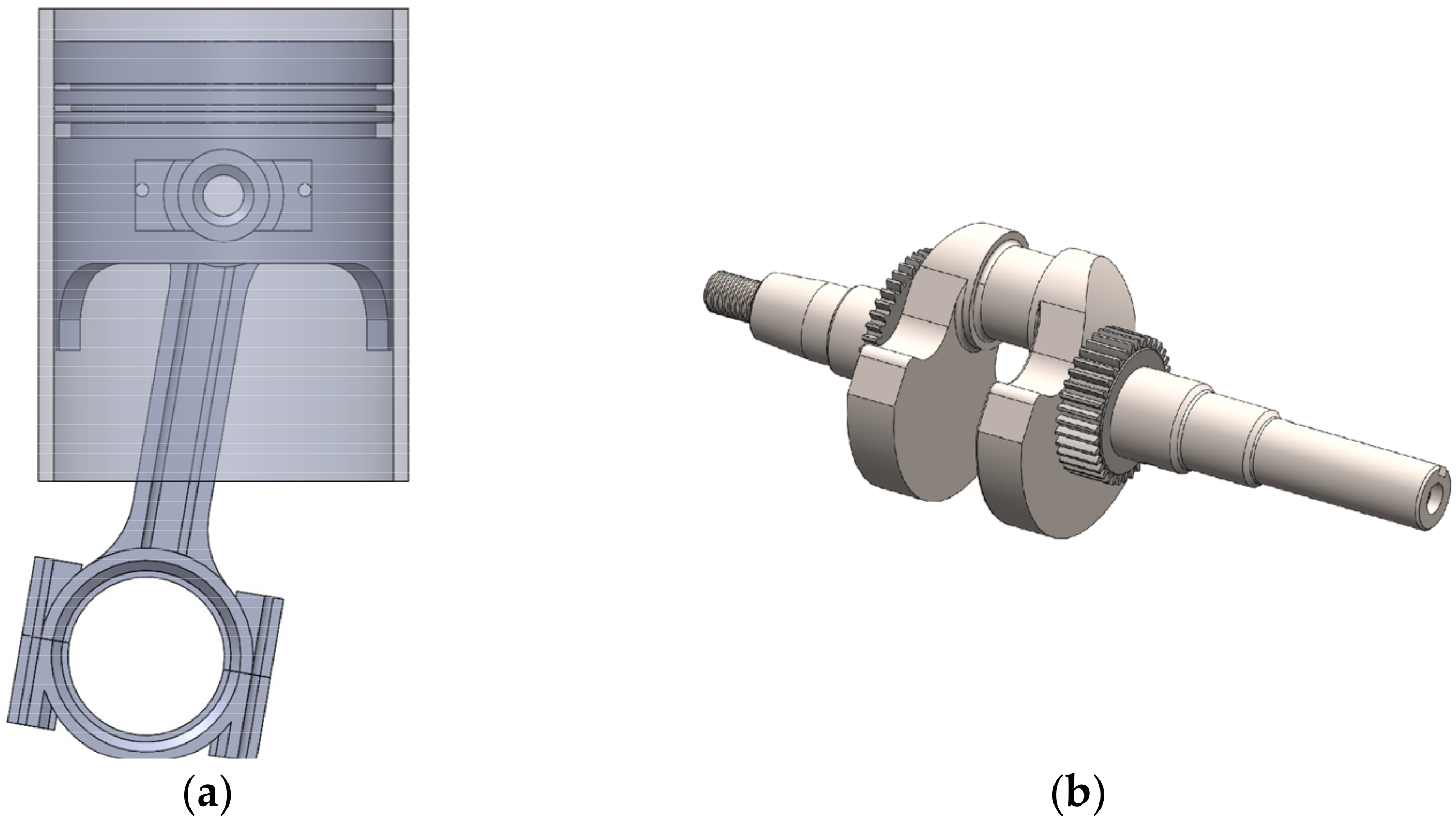
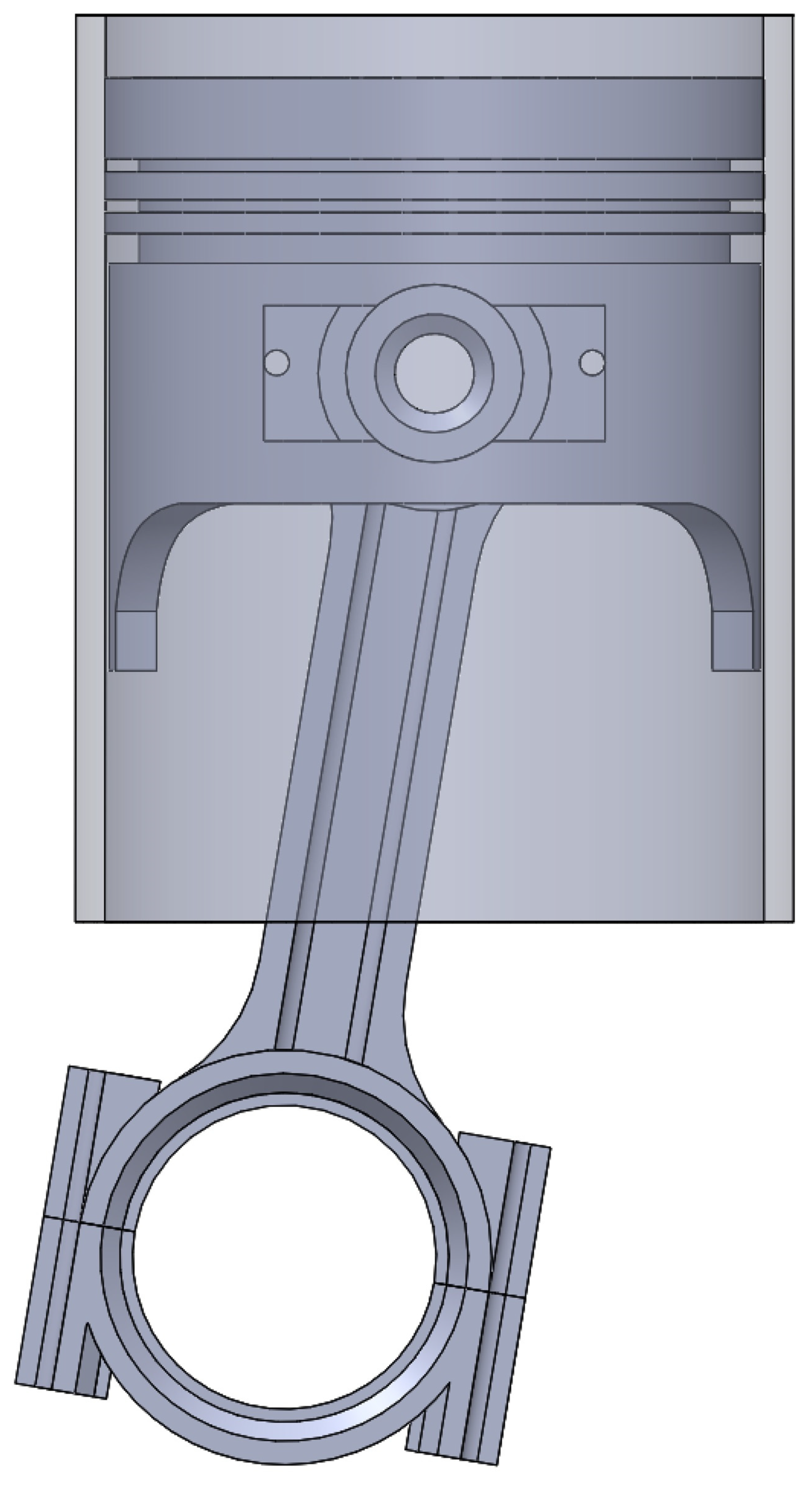
To predict the kinematic movement and the load conditions of the piston, a CFD model of the engine geometry was made, as shown in
Figure 1. Numerical simulations were carried out using the free software OpenFOAM
®. The geometric characteristics of the engine are shown in
Table 1.
For the numerical simulation, a computational domain formed by the surface of the cylinder liner, the surface of the piston rings, and the piston skirt was established. The CFD model also involves part of the engine crankcase and combustion chamber to describe the piston’s entire movement during the combustion cycle. For the development of the research, a torque condition of 250 Nm and a rotation speed of 2000 rpm in the engine were used as a reference.
The Navier–Stokes’s equations were used to govern the behavior of the numerical simulation. The mesh of the geometry was built using the SALOME software. The convergence was defined in a residual value of 10
−4, 10
−7, and 10
−4 in the dissipation rate, energy, and turbulence kinetic energy, respectively [
37]. The properties of the lubricating oil between the cylinder liner and the piston rings are described in
Table 2, the characteristics of which are based on the SAE 10W40 lubricant.
The general methodology used for this research is described in
Figure 2.
From the reference engine, the geometric characteristics of the piston, crankshaft, and connecting rod for the CFD model were obtained. Additionally, data from the experimental tests were collected to define the boundary conditions of the numerical simulation, such as flow, temperature, and pressure. For the initial condition of the lubrication film between the cylinder liner and the piston rings, a distribution of 10% oil and 90% air was established, respectively.
4. Experimental Validation
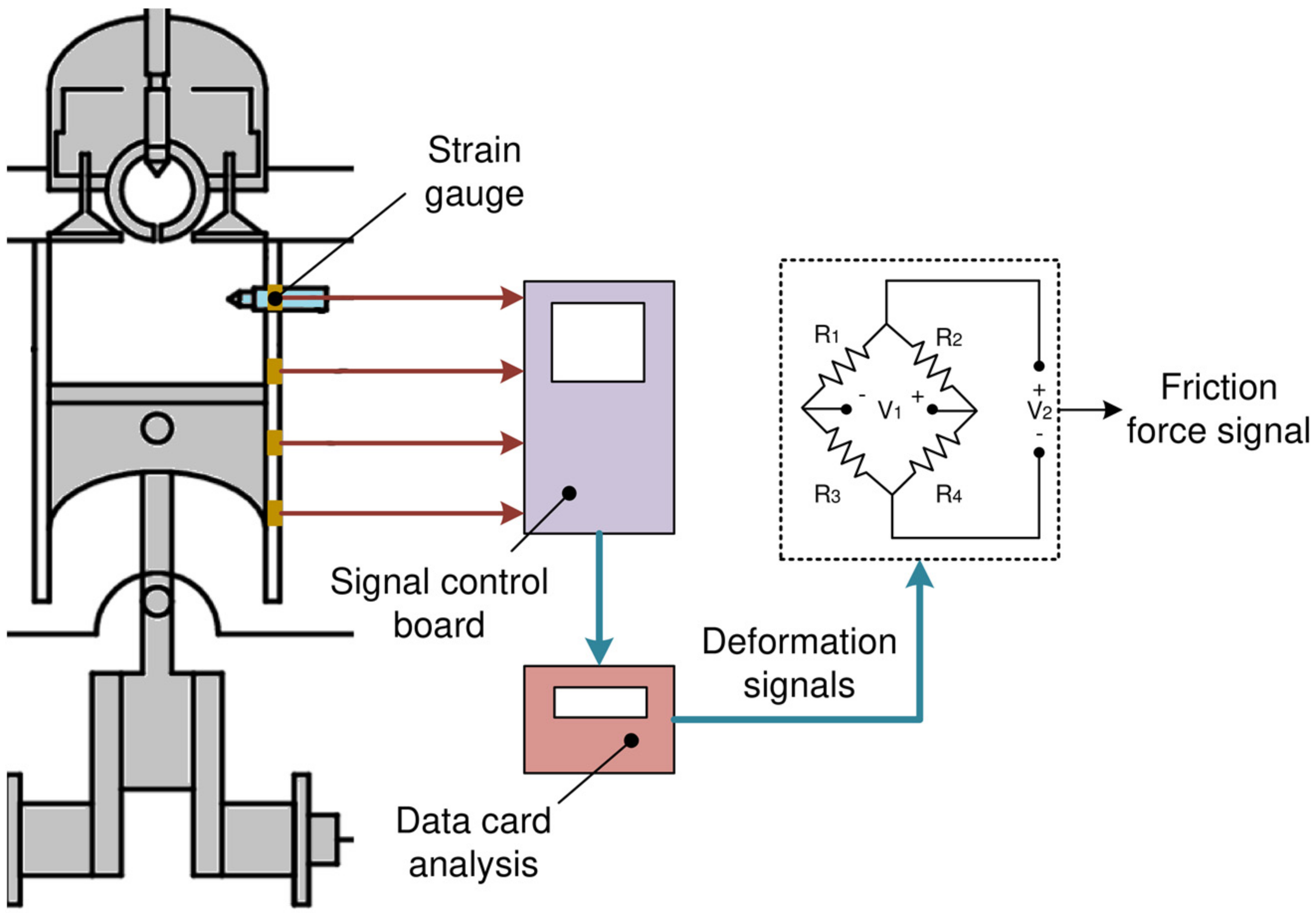
To verify the prediction capacity of the numerical model, a comparison was made with the friction force on the cylinder liner, obtained through experimental tests. The friction force measurement was carried out using a strain gauge sensor to calculate the deformation in the cylinder liner. The characteristics of the sensor are shown in
Table 3.
The determination of the experimental friction force
was carried out using Equations (24) and (25) [
38].
where
is the voltage,
is the area of the strain gauge sensor,
is the calibration factor of the strain gage
, and
is the longitudinal unit strain of the sensor. The experimental setup for friction force signal processing is indicated in
Figure 3.
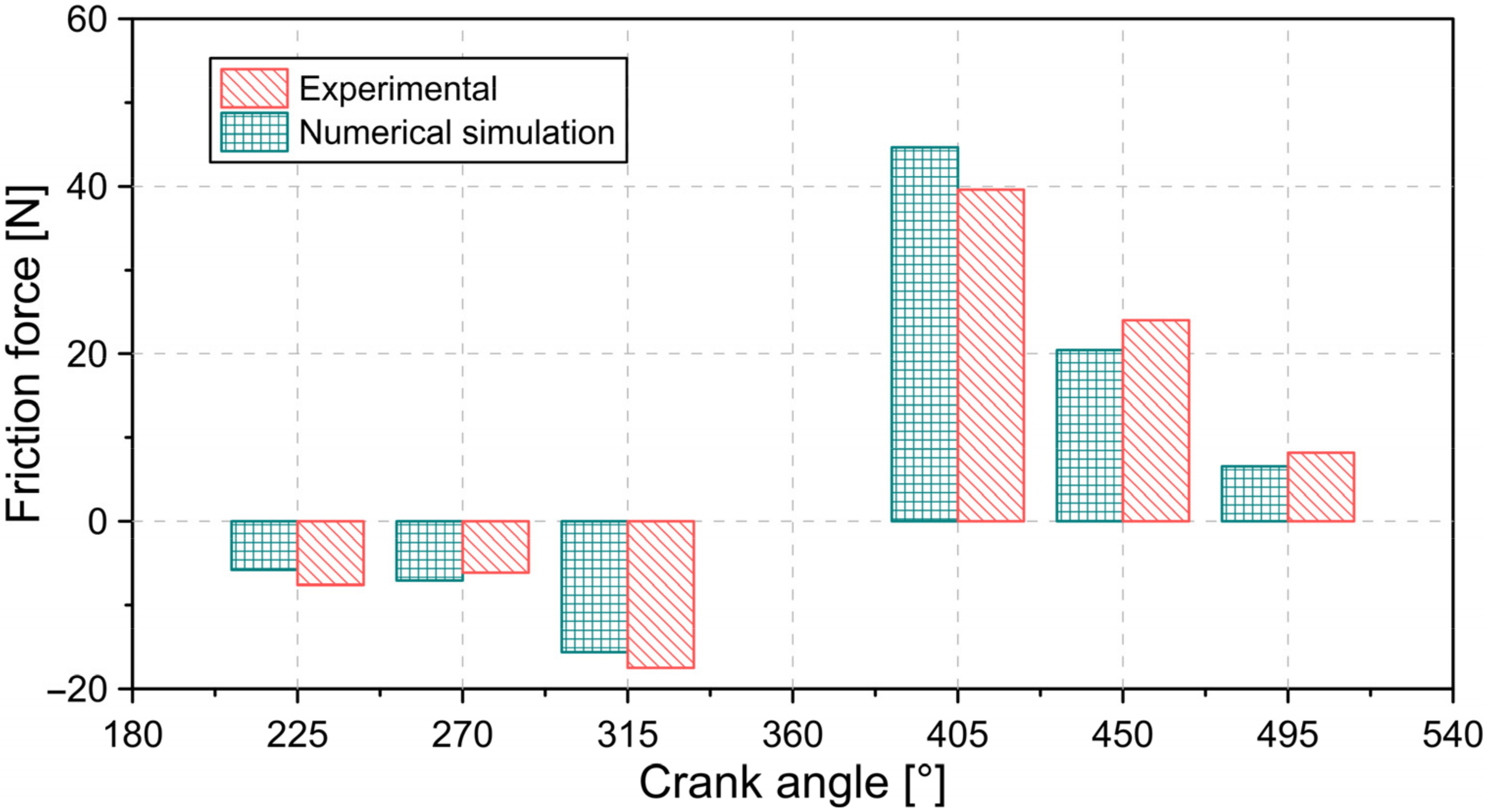
Figure 4 shows the comparison of the friction force between the experimental results and the numerical simulation for different crank angle positions.
From the comparison shown in
Figure 4, it is possible to demonstrate an adequate concordance between the predictions of the numerical model and the results obtained from the experimental tests. On average, a relative error of 16% was obtained with a maximum error of 23%, which is in agreement with the investigations reported in the literature [
39,
40]. Deviations from numerical predictions can be a consequence of several variables, such as pressure change in the combustion chamber, lubrication film irregularities, and changes in lubricant properties.
5. Results and Discussion
5.1. Analysis of Combustion Chamber Conditions
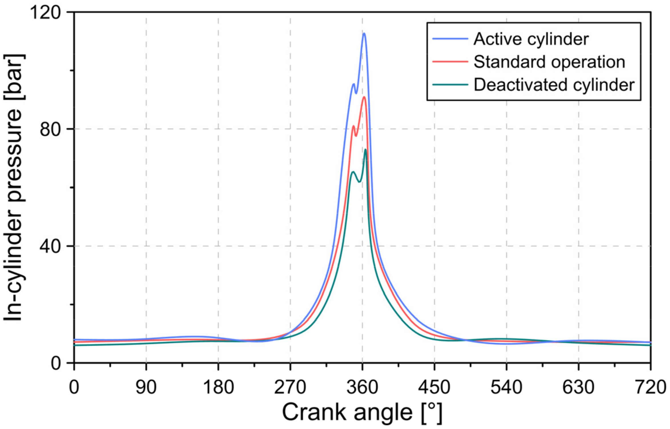
During the cylinder deactivation process, two cylinders are active, and two cylinders are deactivated. Under standard operating conditions, all four engine cylinders remain operational.
Figure 5 shows the behavior of the pressure in the active cylinder chamber, the deactivated cylinder, and the cylinder under normal engine operating conditions.
The results of
Figure 5 show that the minimum pressure in the combustion chamber occurs in the deactivated cylinder. This is a consequence of the closing of the intake valves and the exhaust valves on the deactivated cylinders. Therefore, only residual exhaust gas inside the cylinder is compressed and expanded. The opposite case occurs with the pressure in the active cylinders, which have the maximum combustion pressure. This pressure increase is necessary to maintain the same output power in relation to standard operating conditions. For the simulated conditions, a maximum combustion pressure of 111 bar, 89 bar, and 72 bar was obtained in the active cylinder, cylinder in standard conditions, and cylinder deactivated, respectively.
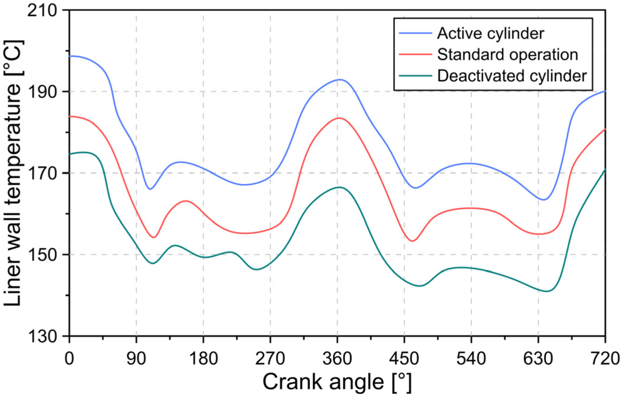
Figure 6 describes the cylinder wall temperature for the different conditions in the engine cylinders. The location of the liner wall used for the construction of the temperature curves is shown in
Figure 7.
In general, the results of
Figure 6 show that the interior of the active cylinder presents the highest temperature in the cylinder wall, which is maintained throughout the combustion cycle. On average, an average temperature of 179, 166, and 154 °C was observed in the active cylinder, cylinder in standard conditions, and cylinder deactivated, respectively. The results obtained are in agreement with what is reported in the literature [
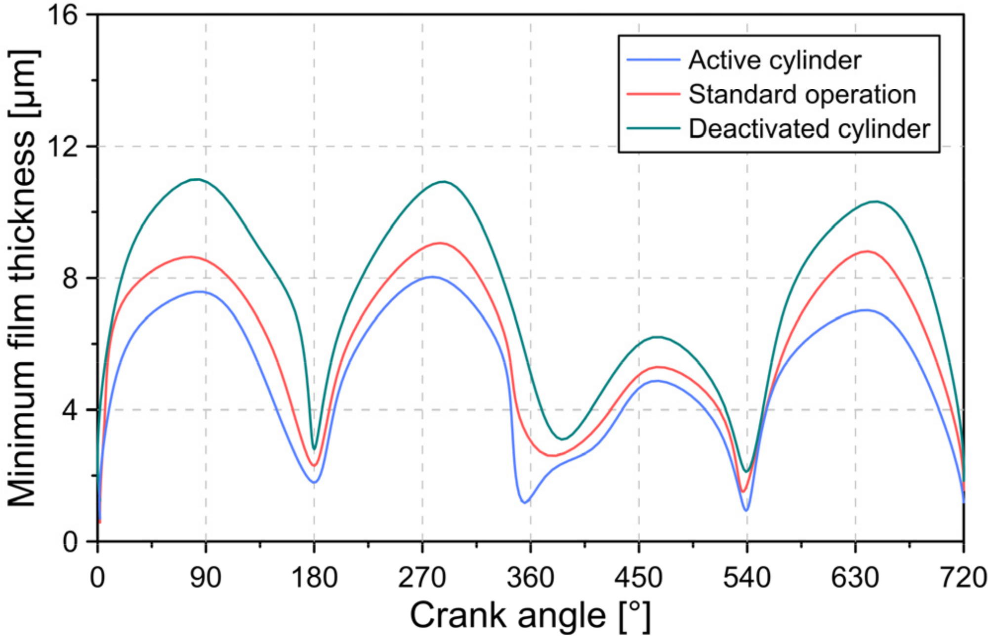
41]. The change in temperature has an effect on the physicochemical properties of the lubricating oil and, thus, on the minimum thickness of the lubrication film, as shown in
Figure 8.
From the results described in
Figure 8, it is evident that the condition of the active cylinder, cylinder in standard conditions, and cylinder deactivated have a significant influence on the minimum thickness of the lubrication film located between the cylinder liner and the piston rings. It was observed that the highest film thickness was located in the deactivated cylinder, which is directly associated with the lower pressure and temperature conditions of the lubricant. From the analysis of the thickness trend for the active cylinder, it is identified that the high temperature and the high load condition due to the increase in pressure lead to a drastic reduction in the thickness of the lubrication film. For the conditions tested, an increase of 23.80% and a reduction of 11.33% in the maximum thickness were obtained for the deactivated cylinder and the active cylinder compared to the standard conditions of the engine, respectively. The results obtained are in agreement with what is reported in the literature [
41]. In general, the maximum thickness values were located in the middle position of the piston stroke. The greatest risk of cylinder liner wear occurs at the top dead center (TDC) and bottom dead center (BDC) of the engine.
5.2. Friction Force Analysis
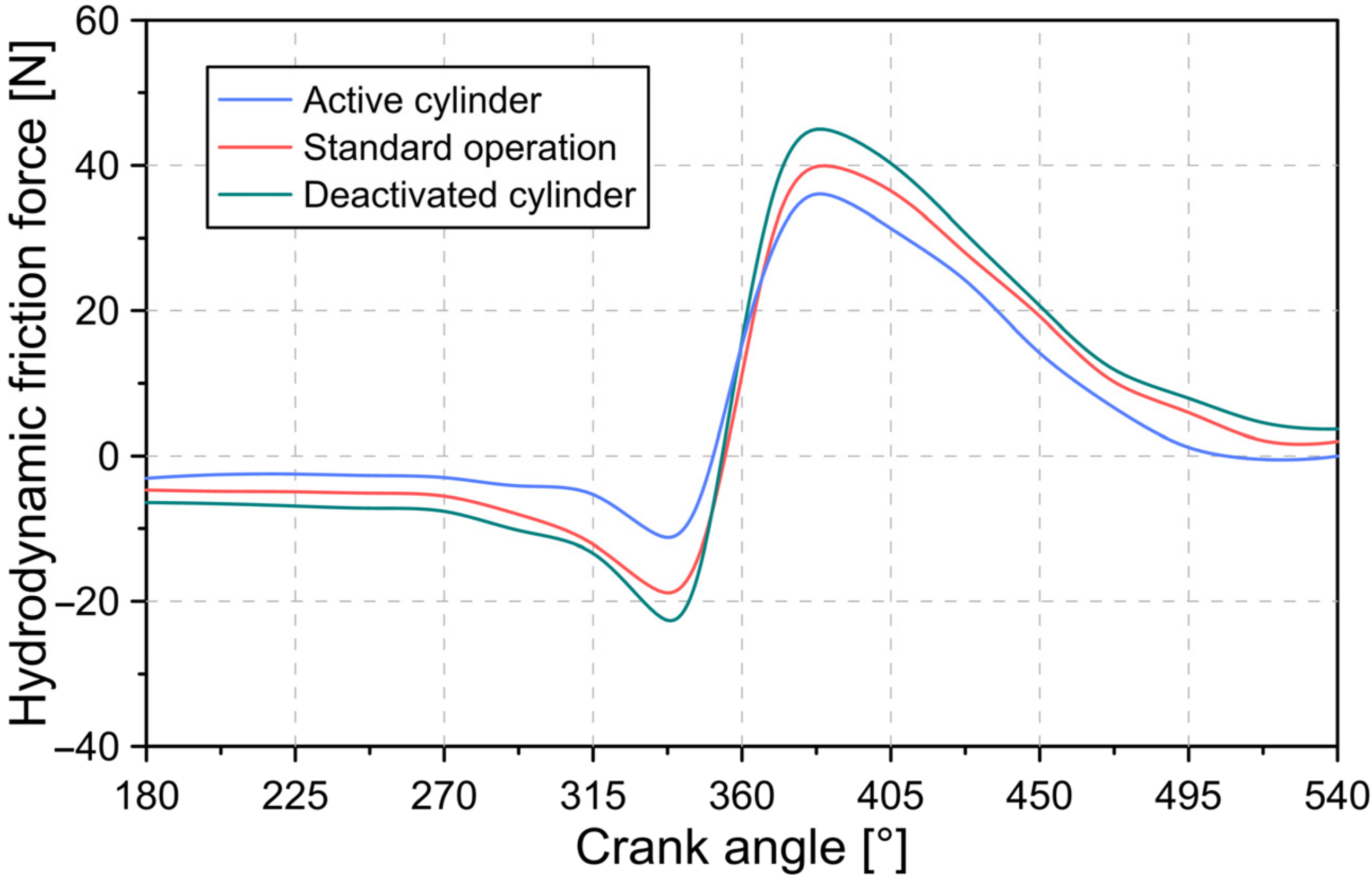
Figure 9 shows the behavior of the hydrodynamic force for the active cylinder, cylinder in standard conditions, and cylinder deactivated.
The hydrodynamic force is directly related to the viscous forces of the lubricating oil. Compared to the cylinder in standard conditions, the high wall temperature in the active cylinder causes a reduction in the viscosity of the lubricating oil. Due to the above, a lower hydrodynamic friction force was obtained compared to the other conditions in the cylinders. The maximum hydrodynamic friction force recorded was 36.05, 39.85, and 45.01 N for the active cylinder, cylinder in standard conditions, and cylinder deactivated, respectively.
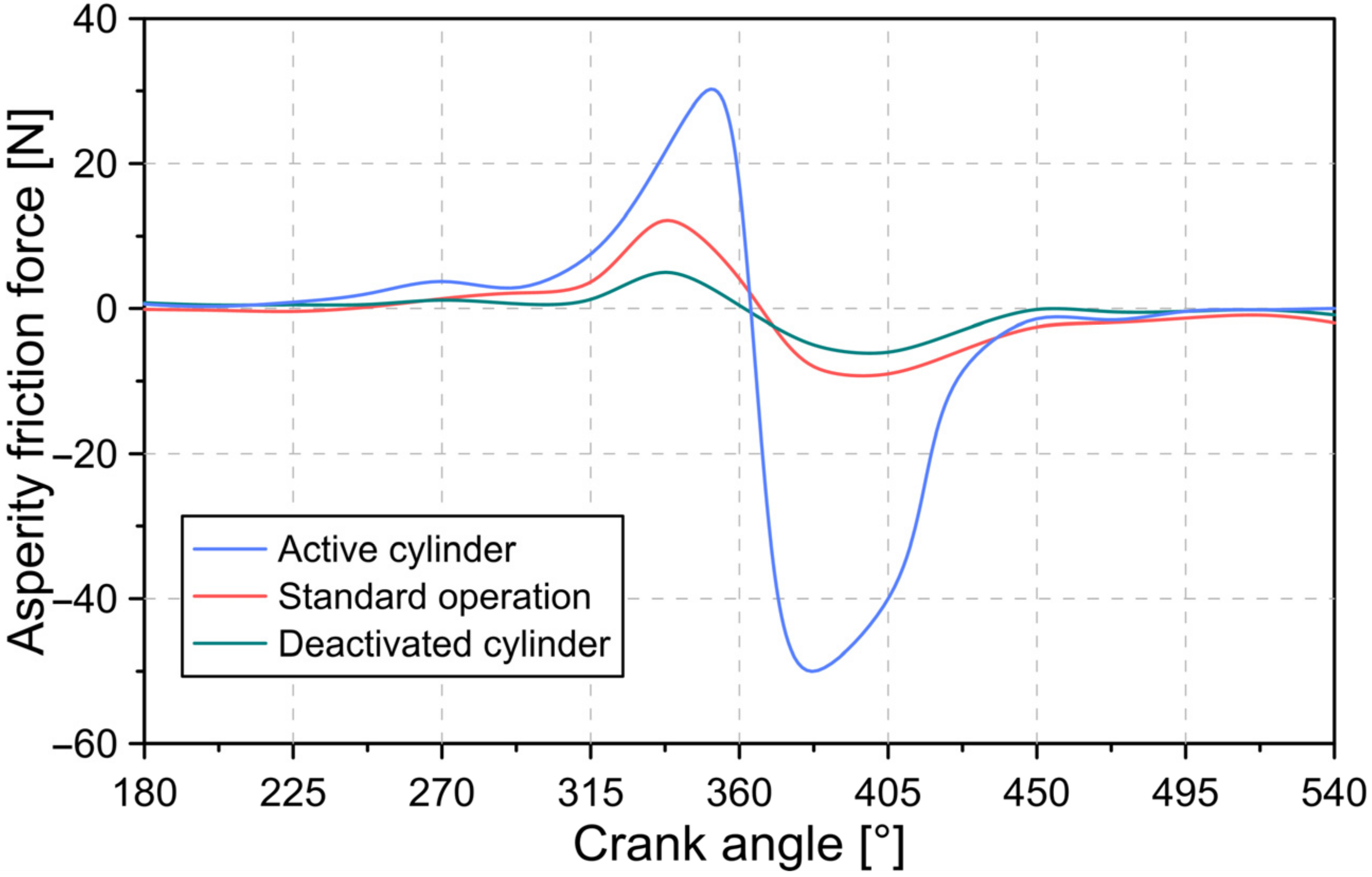
Asperity friction force trends for each cylinder are shown in
Figure 10.
Unlike the behavior described in
Figure 9, the active cylinder presents a considerable increase in the friction force due to asperity in comparison with the cylinder in standard conditions and the cylinder deactivated. This result is a consequence of the greater thinning in the thickness of the lubrication film, as shown in
Figure 8. This facilitates the contact between the rough surfaces of the piston rings and the cylinder liner. The greatest roughness friction force on the active cylinder occurs during the expansion stage of the engine.
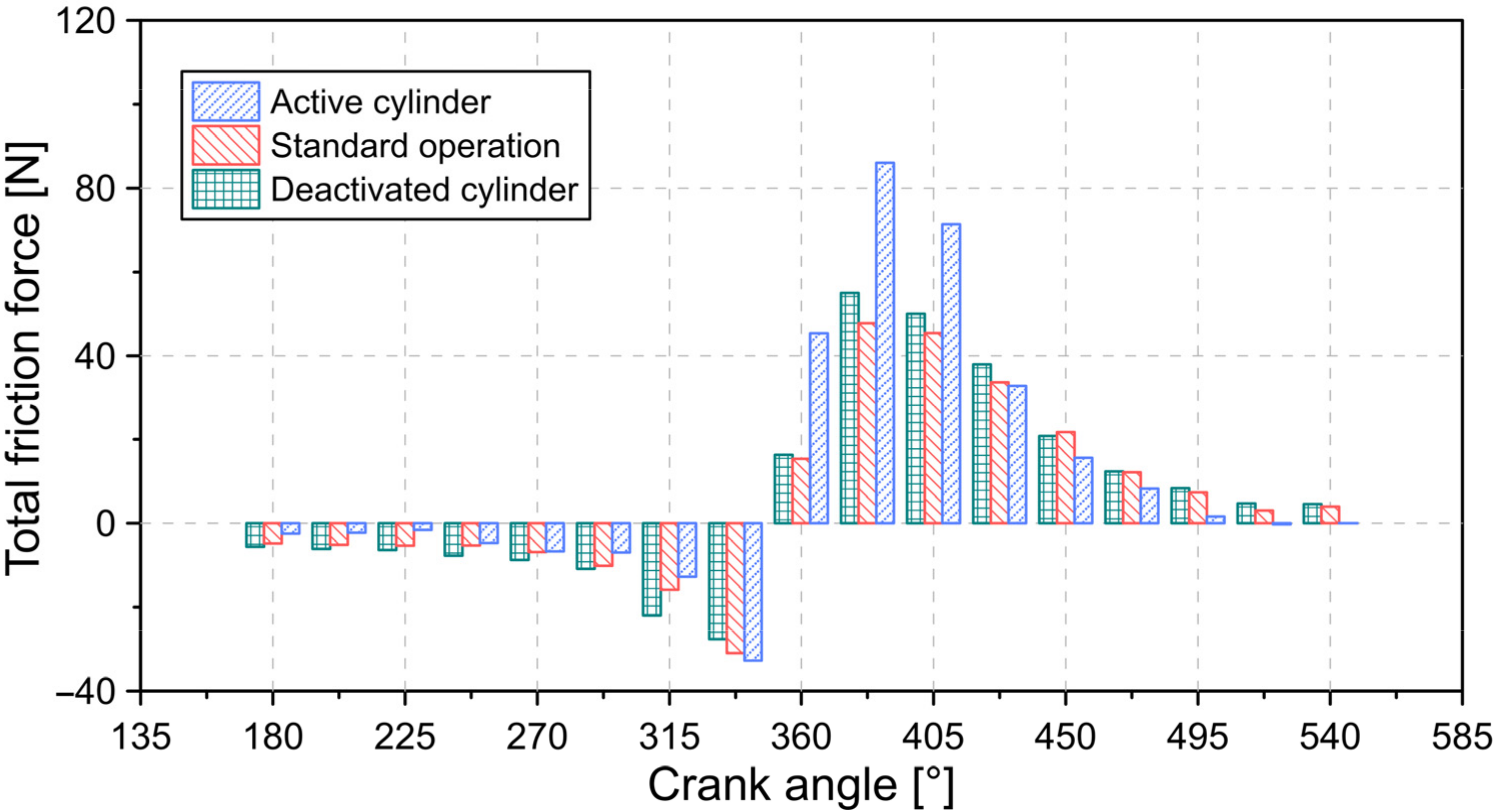
The behavior of the total friction force throughout the combustion cycle is shown in
Figure 11.
In general, the deactivated cylinder exhibits a higher friction force compared to the cylinder in standard conditions. This behavior may be a consequence of the greater hydrodynamic friction force, as evidenced in
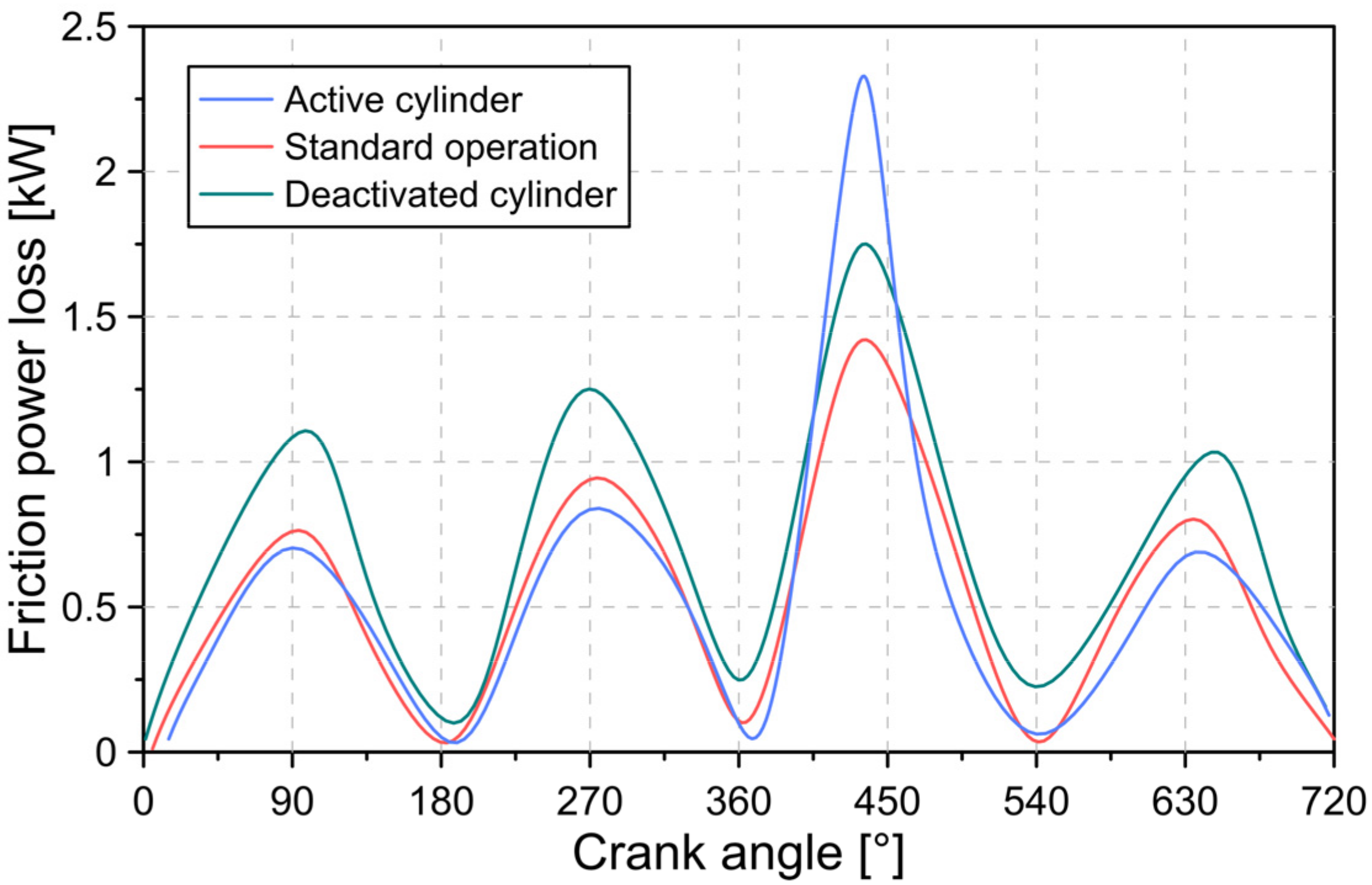
Figure 9. During the intake and exhaust stages of the combustion cycle, it was observed that the minimum total friction force was present in the active cylinder. However, this behavior changed during the expansion stage as a result of the high asperity friction force in the active cylinder. The maximum total friction force recorded was 86.05, 47.85, and 55.01 N for the active cylinder, cylinder in standard conditions, and cylinder deactivated, respectively. This has a direct impact on the power losses between the piston rings and the cylinder liner, as indicated in
Figure 12.
On average, the power loss due to friction was 0.51, 0.48, and 0.61 kW for the active cylinder, cylinder in standard conditions, and cylinder deactivated, respectively. The foregoing implies an increase in power loss by 63.90% and 23.17% for the active cylinder and deactivated cylinder compared to the standard conditions. Therefore, it is evident that the cylinder deactivation technology influences the tribological performance and the power loss by friction.
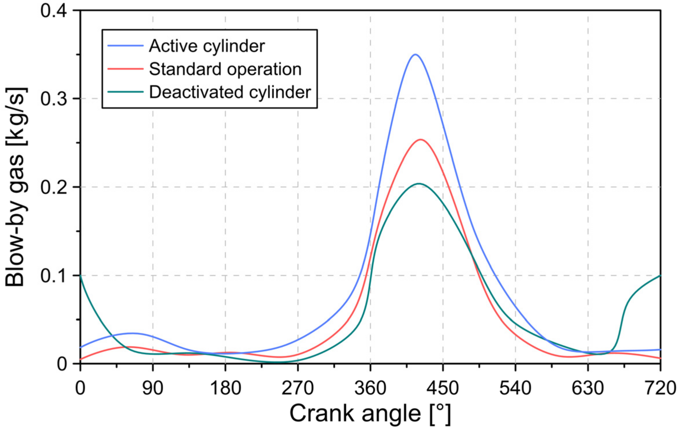
5.3. Blow-by Gas Analysis
Figure 13 illustrates the flow of gases into the crankcase throughout the combustion cycle for various in-cylinder conditions.
In general, the greatest amount of combustion gas leakage occurs during the compression and expansion stages. However, in the case of the deactivated cylinders, additional leaks between the intake and exhaust stages were evidenced, which is due to the second compression of the combustion gases during the cycle by the closure of the intake and exhaust valves. The maximum recorded exhaust flow was 0.35, 0.25, and 0.20 kg/s for the active cylinder, standard condition cylinder, and deactivated cylinder, respectively. The greater number of leaks in the active cylinders is a consequence of the high pressure in the combustion chamber and the reduction in the thickness in the lubrication film.
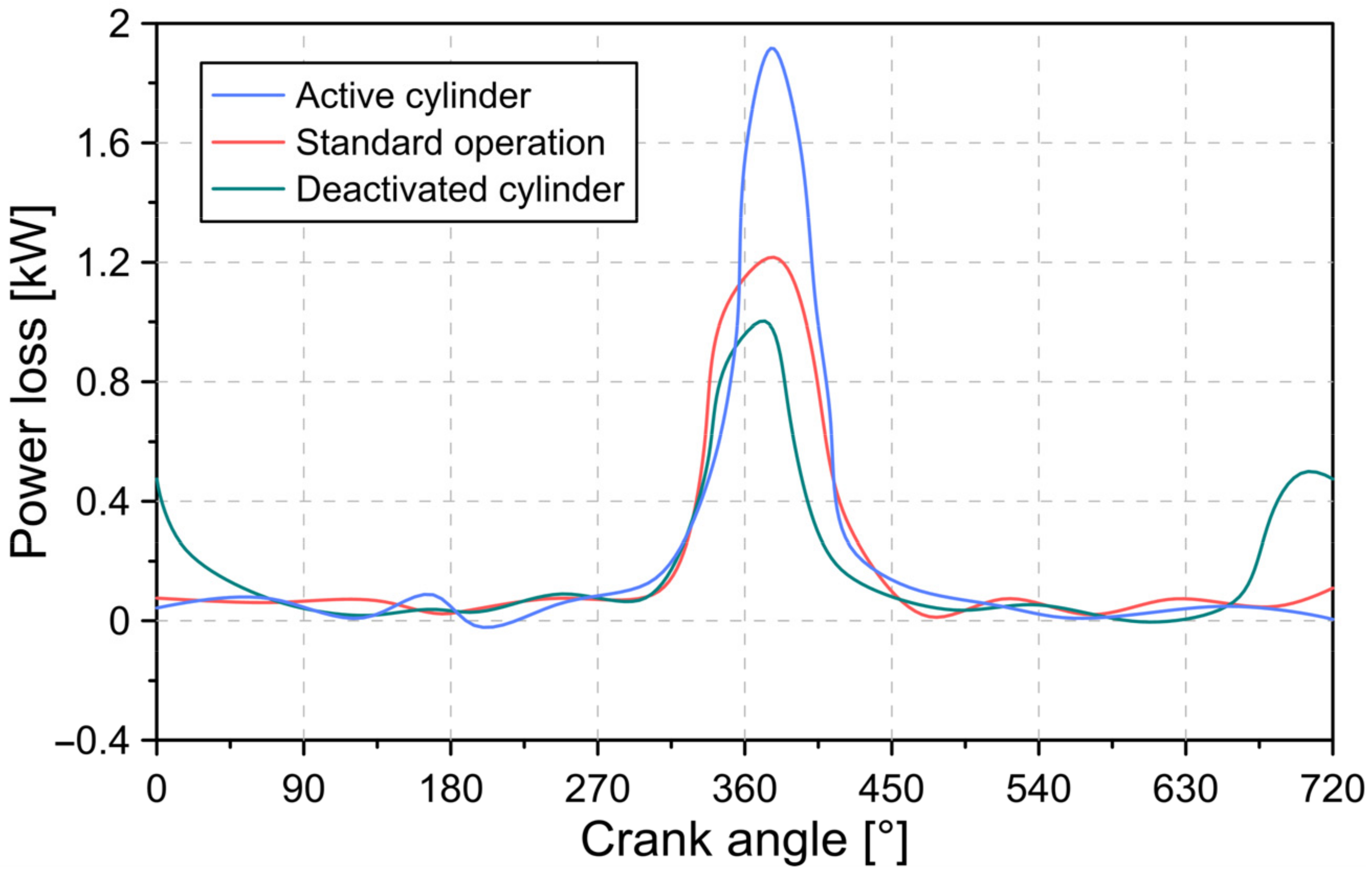
The impact of blow-by gas on power loss is shown in
Figure 14.
The results shown in
Figure 14 describe a behavior similar to that observed in
Figure 13. In general, the active cylinders cause an increase of 57.51% in the loss of power due to maximum leaks compared to the standard conditions. However, in the deactivated cylinders, a reduction of 17.60%, respectively, was obtained. This allows demonstrating that cylinder deactivation causes a significant increase in combustion cycle losses, which must be considered to evaluate the performance of internal combustion engines operating with cylinder deactivation technologies.
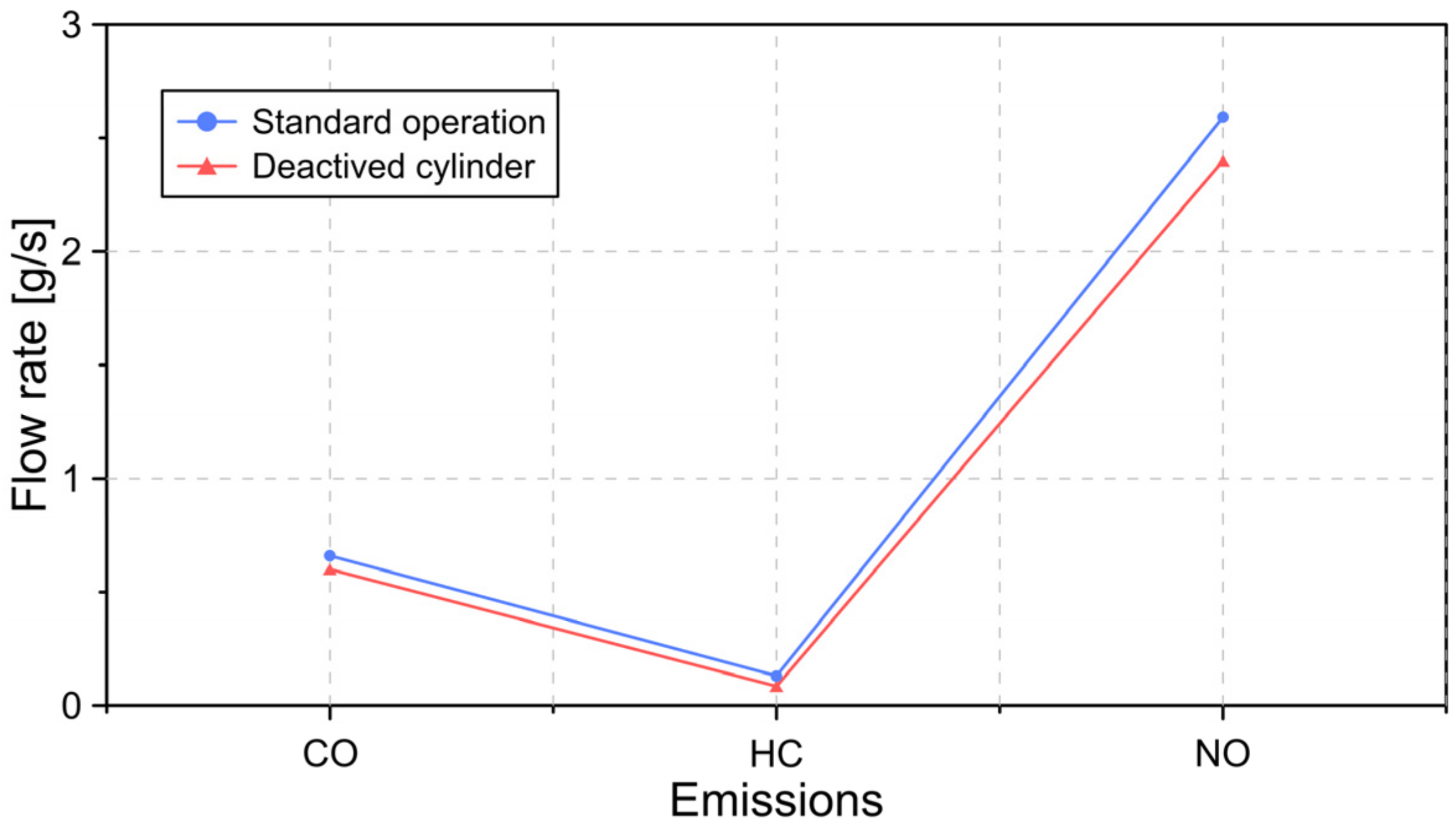
The effect of cylinder deactivation on emissions caused by combustion gases present in piston ring crevices is depicted in
Figure 15.
From the results described in
Figure 15, it is observed that the use of technologies such as cylinder deactivation allows reducing CO, HC, and NO emissions caused by combustion gases trapped in the crevices of the piston rings. This reduction implies less formation of unburned fuel inside the combustion chamber, which may be associated with the increase in the temperature of the cylinder wall. This behavior is in agreement with the results described in the literature [
42]. Additionally, the increase in the temperature of the lubricating oil prevents its accumulation in the combustion chamber. This enables the oil evaporation rate to be reduced and, therefore, emissions. In general, a reduction of 9.09%, 8.26%, and 7.41% in CO, HC, and NO emissions, respectively, was evidenced.
6. Conclusions
In the present investigation, an analysis of the influence of technologies such as cylinder deactivation on the tribological characteristics and emission conditions in an internal combustion engine was carried out. For the development of the study, a tribological model was used, which was used to predict the characteristics of the lubrication film, friction conditions, blow-by gas, and deformation of the piston rings. To describe the movement of the piston inside the combustion chamber, a CFD model was built.
From the results, it was possible to demonstrate that the deactivation of cylinders has a high impact on the pressure and temperature conditions inside the combustion chamber. The active cylinders present an increase of 21.53% and 7.65% in the pressure and temperature in the cylinder wall. However, the deactivated cylinders produced a reduction of 19.24% and 7.07% in the previous parameters.
Cylinder deactivation influences the tribological performance between the piston rings and the cylinder liner. The active cylinders present a reduction of 11.33% in the minimum thickness of the lubrication film and an increase in the friction force due to the surface asperities between the piston rings and the cylinder liner. This implied a 33% increase in power losses due to friction.
Another disadvantage of the engine operating with deactivated cylinders is the increase in combustion gas leaks caused by the increase in pressure of the active cylinders and the closing of the intake and exhaust valves in the case of deactivated cylinders. In general, active cylinders show a 40% increase in combustion chamber leakage. However, the increase in cylinder wall temperature caused by cylinder deactivation allows the reduction of unburned fuel, which leads to a decrease of 9.09%, 8.26%, and 7.41% in CO, HC, and NO emissions.
Although the use of technologies such as cylinder deactivation allows significant fuel savings, it is necessary to consider the negative effects caused by this technology, such as the increase in combustion gas leaks and the increase in power loss by the highest frictional forces. This allows a more precise evaluation of the benefits of cylinder deactivation in internal combustion engines.
Author Contributions
Conceptualization, S.O.A.; methodology, S.O.A., software, S.O.A.; validation, M.D.S.F.-V. and C.P.G.; formal analysis, S.O.A., M.D.S.F.-V. and C.P.G.; investigation, S.O.A., M.D.S.F.-V. and C.P.G.; resources, S.O.A., M.D.S.F.-V. and C.P.G.; writing—original draft preparation, S.O.A.; writing—review and editing, M.D.S.F.-V. and C.P.G.; funding acquisition, S.O.A., M.D.S.F.-V. and C.P.G. All authors have read and agreed to the published version of the manuscript.
Funding
This research received no external funding.
Data Availability Statement
Data is contained within the article.
Acknowledgments
The authors would like to acknowledge the Universidad Francisco de Paula Santander for their support in the development of this investigation.
Conflicts of Interest
The authors declare no conflict of interest.
Abbreviations
The following abbreviations are used in this manuscript:
| Thickness of the lubricant |
| Film pressure of the lubricating oil |
| Piston velocity |
| Lubricant piezo-viscosity index |
| Thermo-viscosity index |
| Atmospheric piezo-viscosity coefficient |
| Model constants |
| Minimum oil film thickness |
| Thickness of the oil due to the geometric profile of the piston ring |
| Piston ring axial width |
| Viscous friction force |
| Real area of contact area |
| Apparent contact area |
| Statistical function |
| Asperity friction force |
| Limiting Eyring shear stress |
| Asperity contact load |
| Equivalent Young’s modulus of elasticity |
| Modulus of elasticity of the cylinder liner |
| Modulus of elasticity of the piston ring |
| Poisson’s ratio of the cylinder liner |
| Poisson’s ratio of the piston ring |
| Mass flow |
| Coefficient of discharge |
| Orifice upstream temperature |
| Gas constant |
| Ring end-gap area |
| Compressibility factor |
| Downstream pressure |
| Upstream pressure |
| Second area moment of inertia |
| Ring radius of curvature |
| Radial force acting on the piston ring |
| Tangential force acting on the piston ring |
| Greek Letters |
| η | Viscosity of the lubricant |
| Density of the lubricating oil |
| Coefficient of thermal expansion |
| Thermo-viscosity coefficient |
| Crown height |
| Pressure flow factors |
| Composite roughness |
| Contact factor |
| Shear flow factor |
| Viscous shear stress |
| Asperity distribution per unit contact area |
| Average asperity tip radius of curvature |
| Stribeck lubricant film ratio |
| Coefficient of asperity shear strength |
| Piston ring material density |
| Cross-sectional area of the ring |
| Angular position along the ring circumference |
References
- Gurt, A.; Khonsari, M. The use of entropy in modeling the mechanical degradation of grease. Lubricants 2019, 7, 82. [Google Scholar] [CrossRef] [Green Version]
- Chong, W.W.F.; Hamdan, S.H.; Wong, K.J.; Yusup, S. Modelling Transitions in Regimes of Lubrication for Rough Surface Contact. Lubricants 2019, 7, 77. [Google Scholar] [CrossRef] [Green Version]
- Ochoa, G.V.; Prada, G.; Duarte-Forero, J. Carbon footprint analysis and advanced exergo-environmental modeling of a waste heat recovery system based on a recuperative organic Rankine cycle. J. Clean. Prod. 2020, 274, 122838–122857. [Google Scholar] [CrossRef]
- Leach, F.; Kalghatgi, G.; Stone, R.; Miles, P. The scope for improving the efficiency and environmental impact of internal combustion engines. Transp. Eng. 2020, 1, 100005. [Google Scholar] [CrossRef]
- Richardson, D.E. Review of Power Cylinder Friction for Diesel Engines. J. Eng. Gas Turbines Power 2000, 122, 506–519. [Google Scholar] [CrossRef]
- Valencia, G.; Fontalvo, A.; Duarte Forero, J. Optimization of waste heat recovery in internal combustion engine using a dual-loop organic Rankine cycle: Thermo-economic and environmental footprint analysis. Appl. Therm. Eng. 2021, 182, 116109. [Google Scholar] [CrossRef]
- Morris, N.; Mohammadpour, M.; Rahmani, R.; Rahnejat, H. Optimisation of the piston compression ring for improved energy efficiency of high performance race engines. Proc. Inst. Mech. Eng. Part D J. Automob. Eng. 2017, 231, 1806–1817. [Google Scholar] [CrossRef] [Green Version]
- Oglieve, C.J.; Mohammadpour, M.; Rahnejat, H. Optimisation of the vehicle transmission and the gear-shifting strategy for the minimum fuel consumption and the minimum nitrogen oxide emissions. Proc. Inst. Mech. Eng. Part D J. Automob. Eng. 2017, 231, 883–899. [Google Scholar] [CrossRef] [Green Version]
- Fitzsimons, B. Introduction to the importance of fuel efficiency and role of the Encyclopedic research project. In Proceedings of the IMechE Seminar: A Drive for Fuel Efficiency, Loughborough, UK, 21 September 2011. [Google Scholar]
- Forero, J.D.; Ochoa, G.V.; Alvarado, W.P. Study of the Piston Secondary Movement on the Tribological Performance of a Single Cylinder Low-Displacement Diesel Engine. Lubricants 2020, 8, 97. [Google Scholar] [CrossRef]
- Menzel, G.; Och, S.H.; Mariani, V.C.; Moura, L.M.; Domingues, E. Multi-objective optimization of the volumetric and thermal efficiencies applied to a multi-cylinder internal combustion engine. Energy Convers. Manag. 2020, 216, 112930. [Google Scholar] [CrossRef]
- Balakheli, M.M.; Chahartaghi, M.; Sheykhi, M.; Hashemian, S.M.; Rafiee, N. Analysis of different arrangements of combined cooling, heating and power systems with internal combustion engine from energy, economic and environmental viewpoints. Energy Convers. Manag. 2020, 203, 112253. [Google Scholar] [CrossRef]
- Cao, J.; Jia, M.; Niu, B.; Chang, Y.; Xu, Z.; Liu, H. Establishment of an improved heat transfer model based on an enhanced thermal wall function for internal combustion engines operated under different combustion modes. Energy Convers. Manag. 2019, 195, 748–759. [Google Scholar] [CrossRef]
- Agarwal, A.K.; Mustafi, N.N. Real-world automotive emissions: Monitoring methodologies, and control measures. Renew. Sustain. Energy Rev. 2021, 137, 110624. [Google Scholar] [CrossRef]
- Tornatore, C.; Bozza, F.; De Bellis, V.; Teodosio, L.; Valentino, G.; Marchitto, L. Experimental and numerical study on the influence of cooled EGR on knock tendency, performance and emissions of a downsized spark-ignition engine. Energy 2019, 172, 968–976. [Google Scholar] [CrossRef]
- Dong, H.; Zhao, Z.; Fu, J.; Liu, J.; Li, J.; Liang, K.; Zhou, Q. Experiment and simulation investigation on energy management of a gasoline vehicle and hybrid turbocharger optimization based on equivalent consumption minimization strategy. Energy Convers. Manag. 2020, 226, 113518. [Google Scholar] [CrossRef]
- Nazoktabar, M.; Jazayeri, S.A.; Parsa, M.; Ganji, D.D.; Arshtabar, K. Controlling the optimal combustion phasing in an HCCI engine based on load demand and minimum emissions. Energy 2019, 182, 82–92. [Google Scholar] [CrossRef]
- Yusri, I.M.; Mamat, R.; Najafi, G.; Razman, A.; Awad, O.I.; Azmi, W.H.; Ishak, W.F.W.; Shaiful, A.I.M. Alcohol based automotive fuels from first four alcohol family in compression and spark ignition engine: A review on engine performance and exhaust emissions. Renew. Sustain. Energy Rev. 2017, 77, 169–181. [Google Scholar] [CrossRef] [Green Version]
- García, A.; Monsalve-Serrano, J.; Martínez-Boggio, S.; Wittek, K. Potential of hybrid powertrains in a variable compression ratio downsized turbocharged VVA Spark Ignition engine. Energy 2020, 195, 117039. [Google Scholar] [CrossRef]
- Wittek, K.; Geiger, F.; Vaz, M.G.J. Characterization of the system behaviour of a variable compression ratio (VCR) connecting rod with eccentrically piston pin suspension and hydraulic moment support. Energy Convers. Manag. 2020, 213, 112814. [Google Scholar] [CrossRef]
- López, J.J.; Garcia, A.; Monsalve-Serrano, J.; Cogo, V.; Wittek, K. Potential of a two-stage variable compression ratio downsized spark ignition engine for passenger cars under different driving conditions. Energy Convers. Manag. 2020, 203, 112251. [Google Scholar] [CrossRef]
- Muhamad Said, M.F.; Latiff, Z.A.; Zainal Abidin, S.F.; Zahari, I. Investigation of Intake Valve Strategy on the Cylinder Deactivation Engine. In Applied Mechanics and Materials; Trans Tech Publications Ltd.: Bäch, Switzerland, 2016; Volume 819, pp. 459–465. [Google Scholar]
- Zhao, J.; Xi, Q.; Wang, S.; Wang, S. Improving the partial-load fuel economy of 4-cylinder SI engines by combining variable valve timing and cylinder-deactivation through double intake manifolds. Appl. Therm. Eng. 2018, 141, 245–256. [Google Scholar] [CrossRef]
- Singh, D.; Gu, F.; Fieldhouse, J.D.; Singh, N.; Singal, S.K. Prediction and analysis of engine friction power of a diesel engine influenced by engine speed, load, and lubricant viscosity. Adv. Tribol. 2014, 2014, 928015. [Google Scholar] [CrossRef] [Green Version]
- Bewsher, S.R.; Turnbull, R.; Mohammadpour, M.; Rahmani, R.; Rahnejat, H.; Offner, G.; Knaus, O. Effect of cylinder de-activation on the tribological performance of compression ring conjunction. Proc. Inst. Mech. Eng. Part J J. Eng. Tribol. 2017, 231, 997–1006. [Google Scholar] [CrossRef] [Green Version]
- Tian, T. Dynamic behaviours of piston rings and their practical impact. Part 2: Oil transport, friction and wear of ring/liner interface and the effects of piston and ring dynamics. Proc. Inst. Mech. Eng. Part J J. Eng. Tribol. 2002, 216, 229–248. [Google Scholar] [CrossRef]
- Guo, Y.; Lu, X.; Li, W.; He, T.; Zou, D. A mixed-lubrication model considering elastoplastic contact for a piston ring and application to a ring pack. Proc. Inst. Mech. Eng. Part D J. Automob. Eng. 2015, 229, 174–188. [Google Scholar] [CrossRef]
- Patir, N.; Cheng, H.S. An Average Flow Model for Determining Effects of Three-Dimensional Roughness on Partial Hydrodynamic Lubrication. J. Lubr. Technol. 1978, 100, 12–17. [Google Scholar] [CrossRef]
- Dowson, D.; Higginson, G.R. A Numerical Solution to the Elasto-Hydrodynamic Problem. J. Mech. Eng. Sci. 1959, 1, 6–15. [Google Scholar] [CrossRef]
- Houpert, L. New Results of Traction Force Calculations in Elastohydrodynamic Contacts. J. Tribol. 1985, 107, 241–245. [Google Scholar] [CrossRef]
- Gu, C.; Meng, X.; Xie, Y.; Kong, X. Performance of surface texturing during start-up under starved and mixed lubrication. J. Tribol. 2017, 139, 11702. [Google Scholar] [CrossRef]
- Rahmani, R.; Theodossiades, S.; Rahnejat, H.; Fitzsimons, B. Transient elastohydrodynamic lubrication of rough new or worn piston compression ring conjunction with an out-of-round cylinder bore. Proc. Inst. Mech. Eng. Part J J. Eng. Tribol. 2012, 226, 284–305. [Google Scholar] [CrossRef] [Green Version]
- Teodorescu, M.; Balakrishnan, S.; Rahnejat, H. Integrated Tribological Analysis within a Multi-physics Approach to System Dynamics. In Tribology and Interface Engineering Series; Elsevier: Amsterdam, The Netherlands, 2005; Volume 48, pp. 725–737. [Google Scholar]
- Greenwood, J.A.; Tripp, J.H. The Contact of Two Nominally Flat Rough Surfaces. Proc. Inst. Mech. Eng. 1970, 185, 625–633. [Google Scholar] [CrossRef]
- Turnbull, R.; Dolatabadi, N.; Rahmani, R.; Rahnejat, H. An assessment of gas power leakage and frictional losses from the top compression ring of internal combustion engines. Tribol. Int. 2020, 142, 105991–106002. [Google Scholar] [CrossRef]
- Theaker, M.; Rahmani, R.; Rahnejat, H. Prediction of Ring-Bore Conformance and Contact Condition and Experimental Validation. In Proceedings of the ASME 2012 Internal Combustion Engine Division Spring Technical Conference, Torino, Italy, 6–9 May 2012; pp. 885–892. [Google Scholar]
- Popoola, O.; Cao, Y. The influence of turbulence models on the accuracy of CFD analysis of a reciprocating mechanism driven heat loop. Case Stud. Therm. Eng. 2016, 8, 277–290. [Google Scholar] [CrossRef] [Green Version]
- Zavos, A.; Nikolakopoulos, P.G. Tribology of new thin compression ring of fired engine under controlled conditions-A combined experimental and numerical study. Tribol. Int. 2018, 128, 214–230. [Google Scholar] [CrossRef]
- Tsujiuchi, N.; Koizumi, T.; Hamada, K.; Okamura, M.; Tsukijima, H. Optimization of profile for reduction of piston slap excitation. In SAE Technical Papers; SAE: Warrendale, PA, USA, 2004. [Google Scholar]
- Gore, M.; Theaker, M.; Howell-Smith, S.; Rahnejat, H.; King, P.D. Direct measurement of piston friction of internal-combustion engines using the floating-liner principle. Proc. Inst. Mech. Eng. Part D J. Automob. Eng. 2014, 228, 344–354. [Google Scholar] [CrossRef] [Green Version]
- Morris, N.; Mohammadpour, M.; Rahmani, R.; Johns-Rahnejat, P.M.; Rahnejat, H.; Dowson, D. Effect of cylinder deactivation on tribological performance of piston compression ring and connecting rod bearing. Tribol. Int. 2018, 120, 243–254. [Google Scholar] [CrossRef]
- Wang, X.; Stone, C.R. A study of combustion, instantaneous heat transfer, and emissions in a spark ignition engine during warm-up. Proc. Inst. Mech. Eng. Part D J. Automob. Eng. 2008, 222, 607–618. [Google Scholar] [CrossRef]
Figure 1.
Internal combustion engine geometry (a) piston-connecting rod and (b) crankshaft.
Figure 1.
Internal combustion engine geometry (a) piston-connecting rod and (b) crankshaft.
Figure 2.
Research methodology.
Figure 2.
Research methodology.
Figure 3.
Measurement process of the friction force signal.
Figure 3.
Measurement process of the friction force signal.
Figure 4.
Friction force obtained from numerical simulation and experimental tests.
Figure 4.
Friction force obtained from numerical simulation and experimental tests.
Figure 5.
Combustion chamber pressure conditions for the active cylinder, cylinder in standard conditions, and cylinder deactivated.
Figure 5.
Combustion chamber pressure conditions for the active cylinder, cylinder in standard conditions, and cylinder deactivated.
Figure 6.
Cylinder wall temperature for the active cylinder, cylinder in standard conditions, and cylinder deactivated.
Figure 6.
Cylinder wall temperature for the active cylinder, cylinder in standard conditions, and cylinder deactivated.
Figure 7.
Cylinder liner wall location.
Figure 7.
Cylinder liner wall location.
Figure 8.
Minimum thickness of the lubrication film for the active cylinder, cylinder in standard conditions and cylinder deactivated in flooded lubrication.
Figure 8.
Minimum thickness of the lubrication film for the active cylinder, cylinder in standard conditions and cylinder deactivated in flooded lubrication.
Figure 9.
Hydrodynamic friction force for the active cylinder, cylinder in standard conditions, and cylinder deactivated in flooded lubrication.
Figure 9.
Hydrodynamic friction force for the active cylinder, cylinder in standard conditions, and cylinder deactivated in flooded lubrication.
Figure 10.
Asperity friction force for the active cylinder, cylinder in standard conditions, and cylinder deactivated in flooded lubrication.
Figure 10.
Asperity friction force for the active cylinder, cylinder in standard conditions, and cylinder deactivated in flooded lubrication.
Figure 11.
Total friction force for the active cylinder, cylinder in standard conditions, and cylinder deactivated in flooded lubrication.
Figure 11.
Total friction force for the active cylinder, cylinder in standard conditions, and cylinder deactivated in flooded lubrication.
Figure 12.
Loss power due to friction between the piston rings and the cylinder liner in flooded lubrication.
Figure 12.
Loss power due to friction between the piston rings and the cylinder liner in flooded lubrication.
Figure 13.
Blow-by gas for the active cylinder, cylinder in standard conditions, and cylinder deactivated.
Figure 13.
Blow-by gas for the active cylinder, cylinder in standard conditions, and cylinder deactivated.
Figure 14.
Loss power due to leakage of exhaust gases between the piston rings and the cylinder liner.
Figure 14.
Loss power due to leakage of exhaust gases between the piston rings and the cylinder liner.
Figure 15.
Polluting emissions in standard condition and cylinder deactivation.
Figure 15.
Polluting emissions in standard condition and cylinder deactivation.
Table 1.
Geometric characteristics of the engine.
Table 1.
Geometric characteristics of the engine.
| Parameter | Value | Unit |
|---|
| Piston radius | 39 | mm |
| Piston area | 4778.36 | mm2 |
| Piston mass | 0.305 | kg |
| Crankshaft radius | 48 | mm |
| Length of piston skirt | 48 | mm |
| Stroke | 104.9 | mm |
| Length of connecting rod | 106 | mm |
Table 2.
Lubricating oil properties.
Table 2.
Lubricating oil properties.
| Properties | Unit | SAE 10W40 |
|---|
| Kinematic viscosity (40 °C) | m2/s | |
| Dynamic viscosity (40 °C) | m2/s | |
| Density (40 °C) | kg/m3 | 866 |
| Pressure—viscosity coefficient | m2/N | |
| Flash point | °C | 230 |
Table 3.
Characteristics of the strain gauge sensor.
Table 3.
Characteristics of the strain gauge sensor.
| Parameter | Value | Unit |
|---|
| Maximum operating temperature | 1150 | °C |
| Overall length | 6.30 | mm |
| Gauge resistance | 120 | Ω |
| Gage length | 2.54 | mm |
| Grid width | 4.55 | mm |
| Publisher’s Note: MDPI stays neutral with regard to jurisdictional claims in published maps and institutional affiliations. |
© 2022 by the authors. Licensee MDPI, Basel, Switzerland. This article is an open access article distributed under the terms and conditions of the Creative Commons Attribution (CC BY) license (https://creativecommons.org/licenses/by/4.0/).


