Thrust-Bearing Layout Design of a Large-Sized Hydrostatic Rotary Table to Withstand Eccentric Loads for Horizontal Boring Machine Applications

Abstract
:1. Introduction
2. Model and Research Method
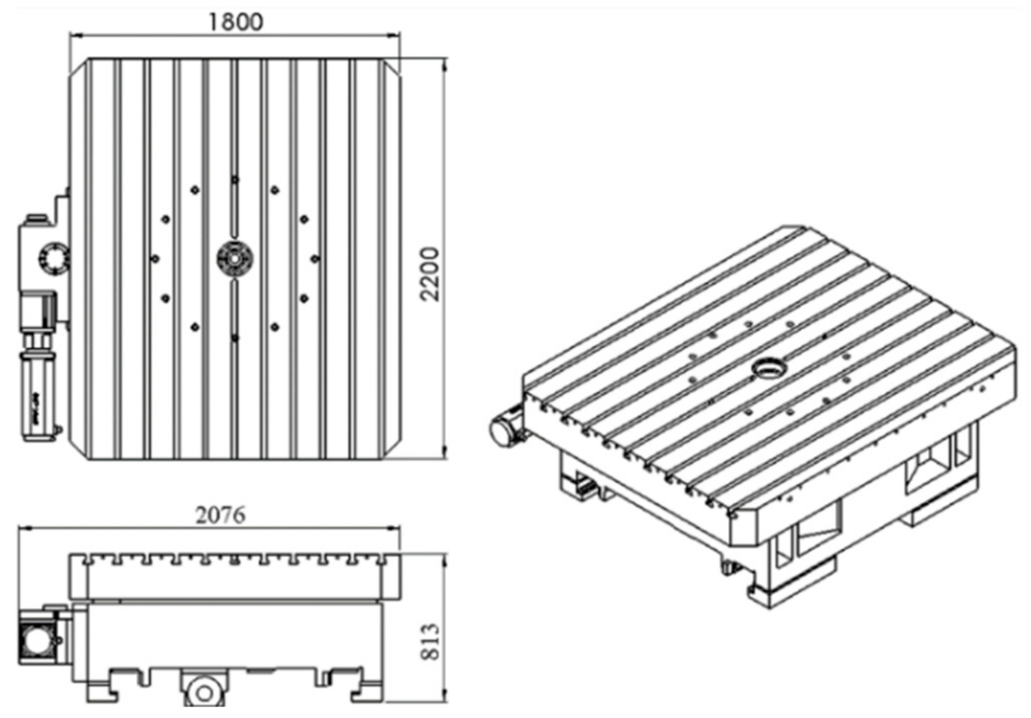
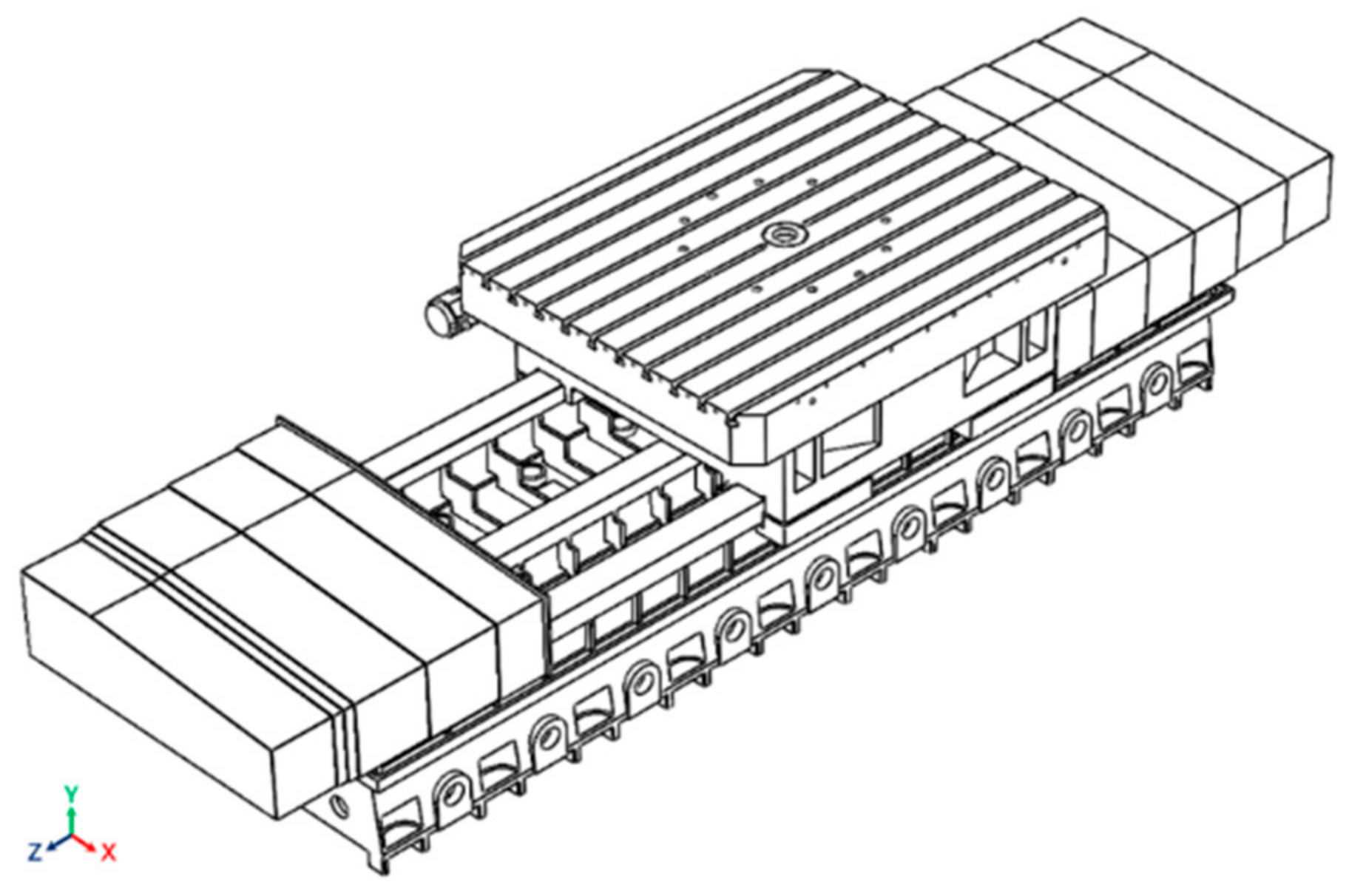
2.1. Introduction to the Research Model
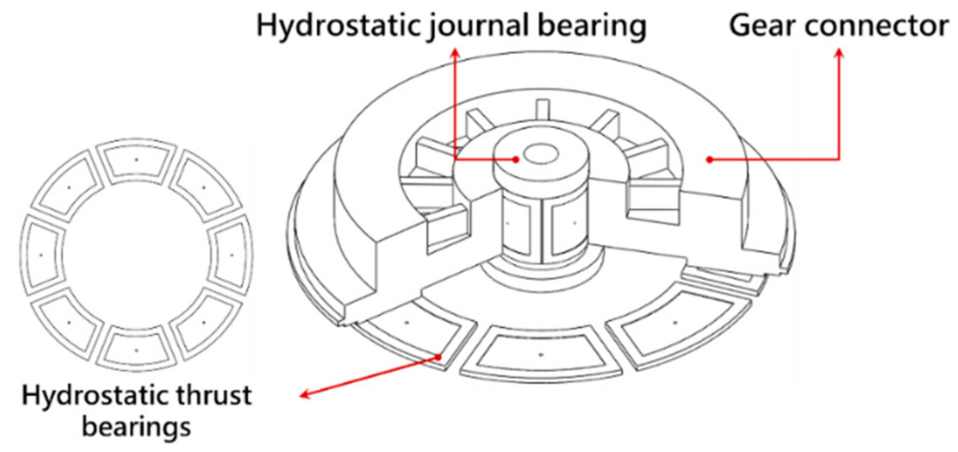
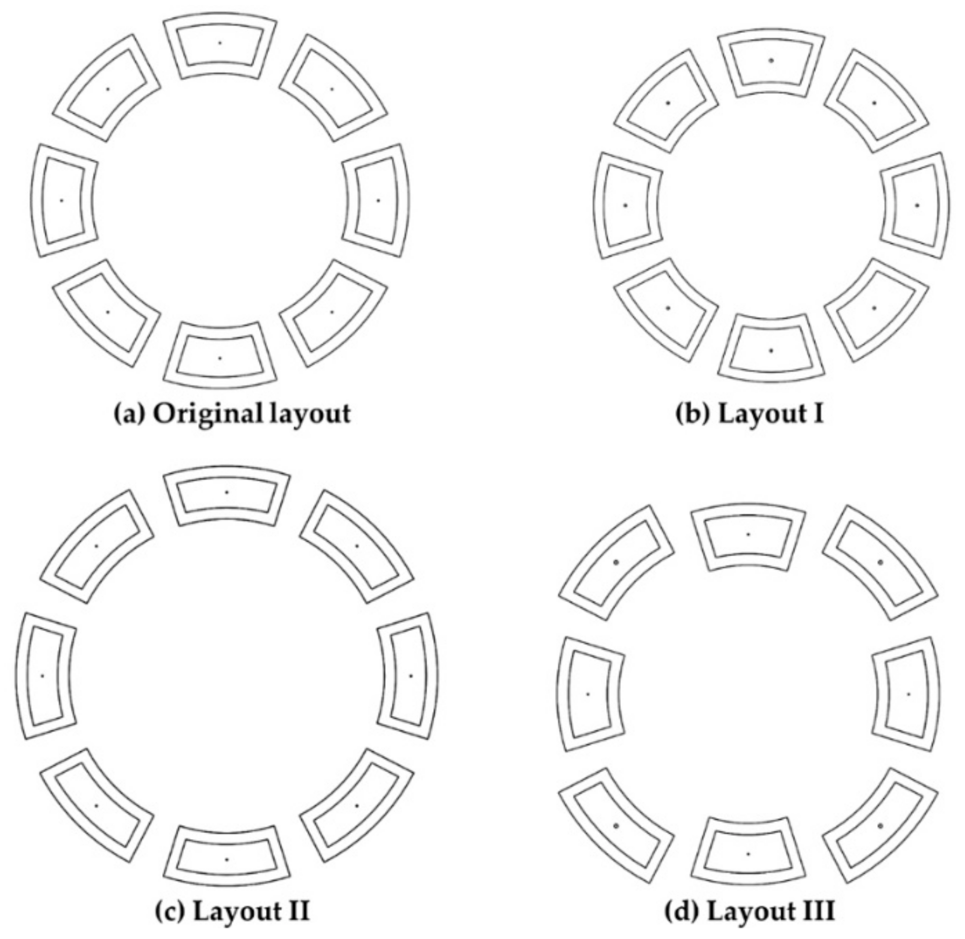
2.1.1. Structural Analysis of the Model
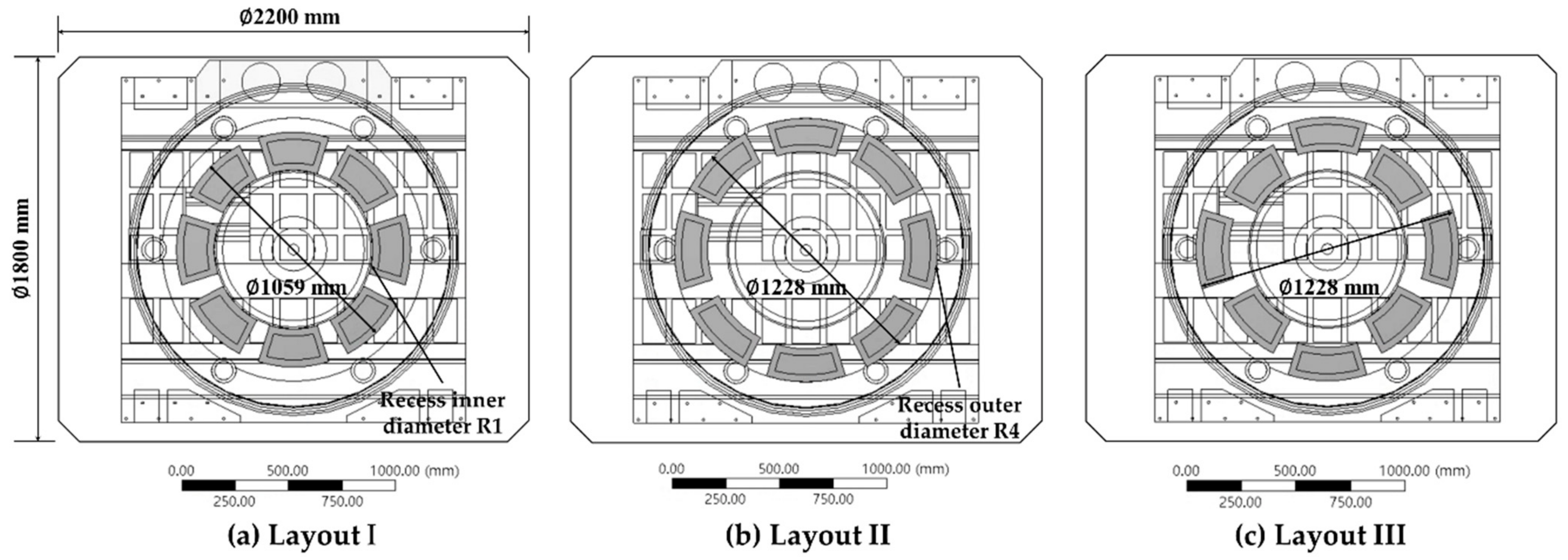
- Layout I: A single-ring recess layout that uses the minimum-diameter recess; the diameter (ø) is 1059 mm, and the internal diameter of the recess (R1) is aligned with the internal diameter of the connector.
- Layout II: A single-ring recess layout that uses the maximum-diameter recess; the diameter (ø) is 1228 mm, and the external diameter of the recess (R4) is aligned with the external diameter of the connector.
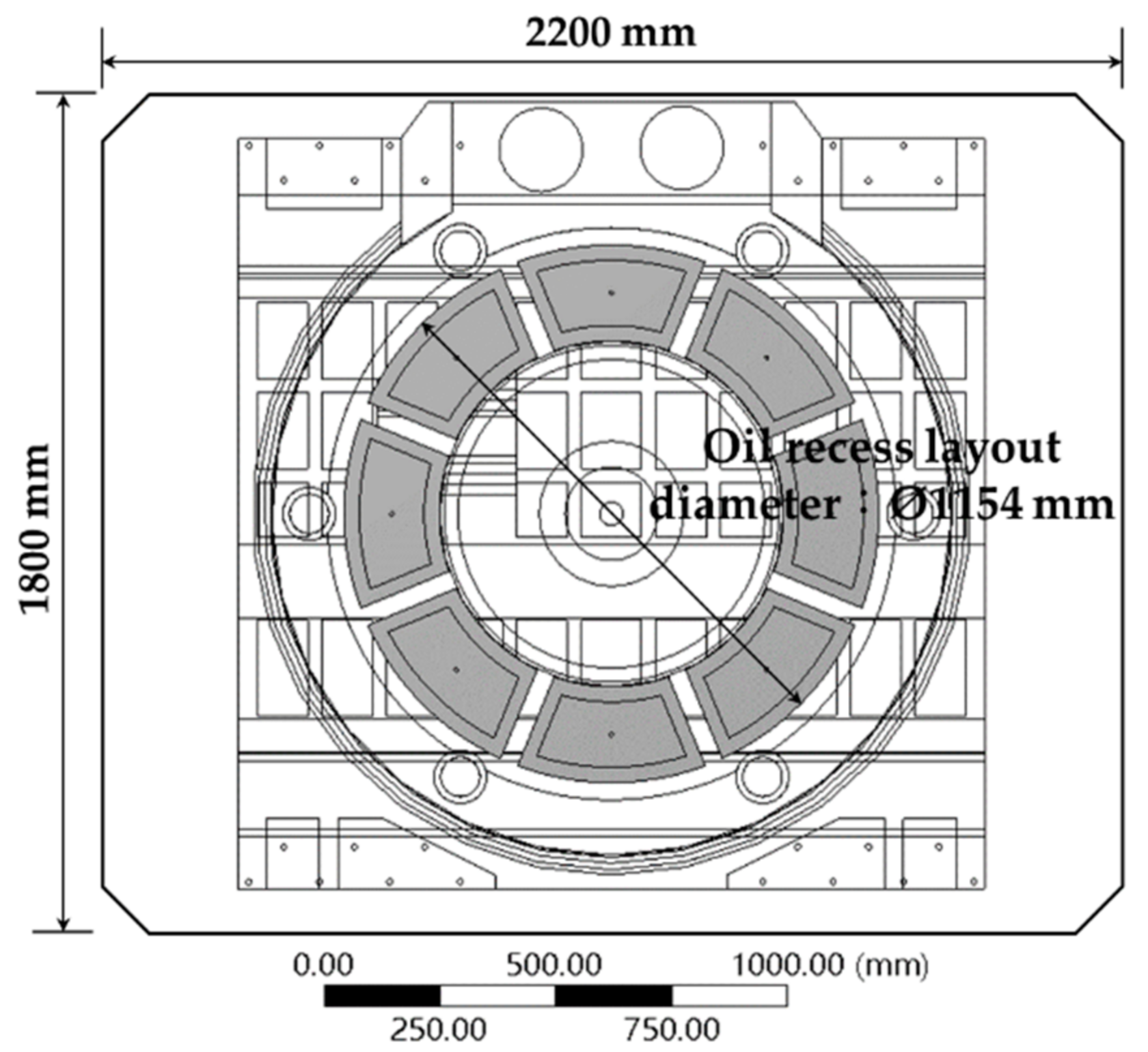
- Layout III: A dual-ring recess layout in which the positions of the minimum-diameter recess and the maximum-diameter recess are staggered.
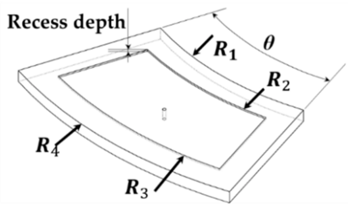
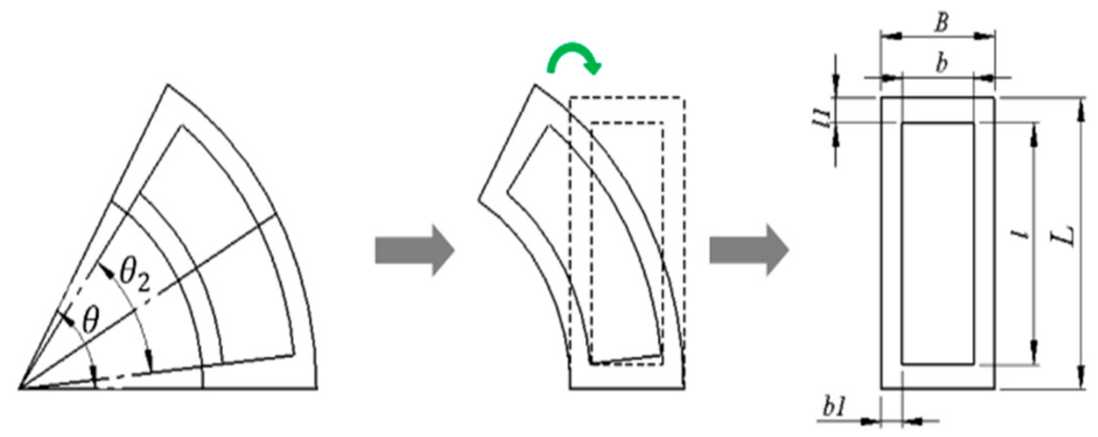
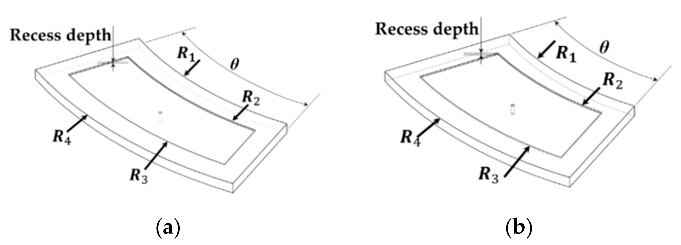
2.1.2. Recess Flow Field Model
2.1.3. Verification of Flow Field Model
2.2. Boundary Conditions of Stimulation
- In the steady-state thermal and the static-structural models, the air-side natural convection temperature of the hydrostatic rotary table model was specified at 27 °C. Since this study only took into account the effects of oil film temperature rise on the hydrostatic rotary table, the simulated temperature rise distribution results of the original and the three new hydrostatic axial thrust bearing designs (as obtained through ANSYS FLUENT software) were jointly incorporated into a structural heat-transfer model in order to perform one-way fluid-solid interactions. The simulated oil film temperature rise distribution results at a maximum rotational speed of 15 rpm were applied to the hydrostatic axial thrust bearing and the hydrostatic journal bearing, while the results at a maximum feed speed of 2 m/min were applied to all recesses in the closed-type hydrostatic slideway.
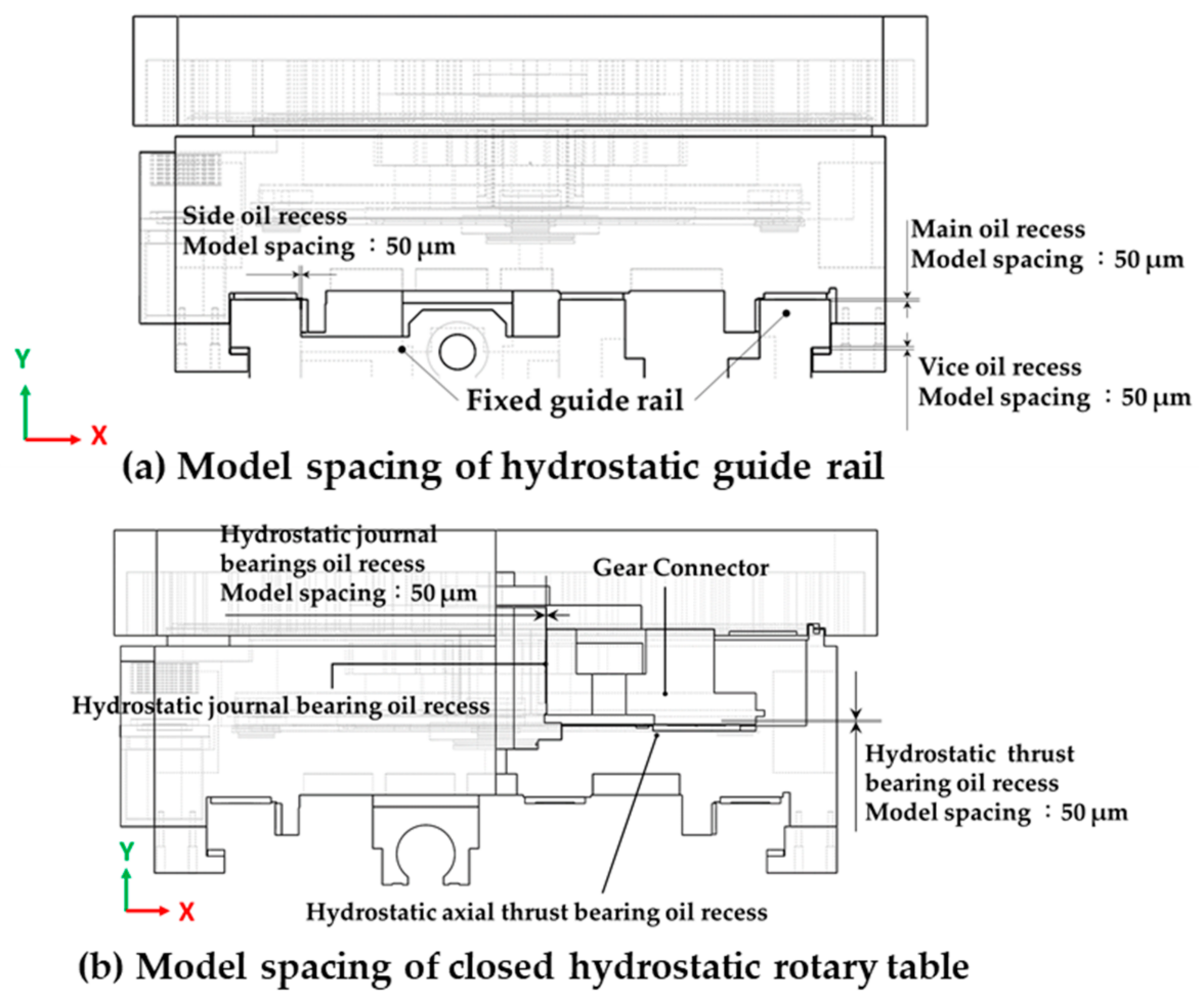
- This study utilized the Joint_Type_Bushing structural model tool to simulate the oil film stiffness of all recesses at the initial oil film thickness. The initial oil film thickness of the recess served as the initial spacing between the structural models simulated through Joint_Type_Bushing. As shown in Figure 12a, the model spacing between the connector and the hydrostatic axial thrust bearing recess was 50 μm; the model spacing between the hydrostatic journal bearing recess and the connector was 50 μm. As shown in Figure 12b, the model spacing between the main and vice recesses and the fixed guide rail was 50 μm; the model spacing between the side recess and the fixed guide rail was 50 μm.
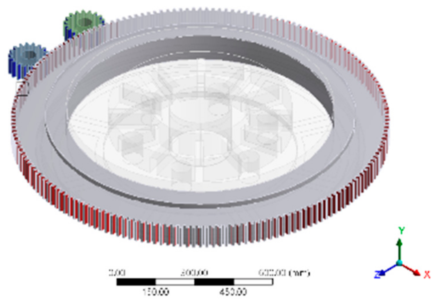
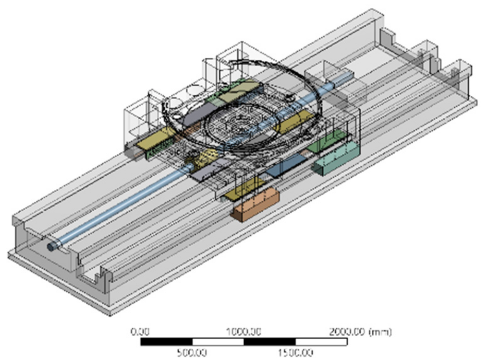
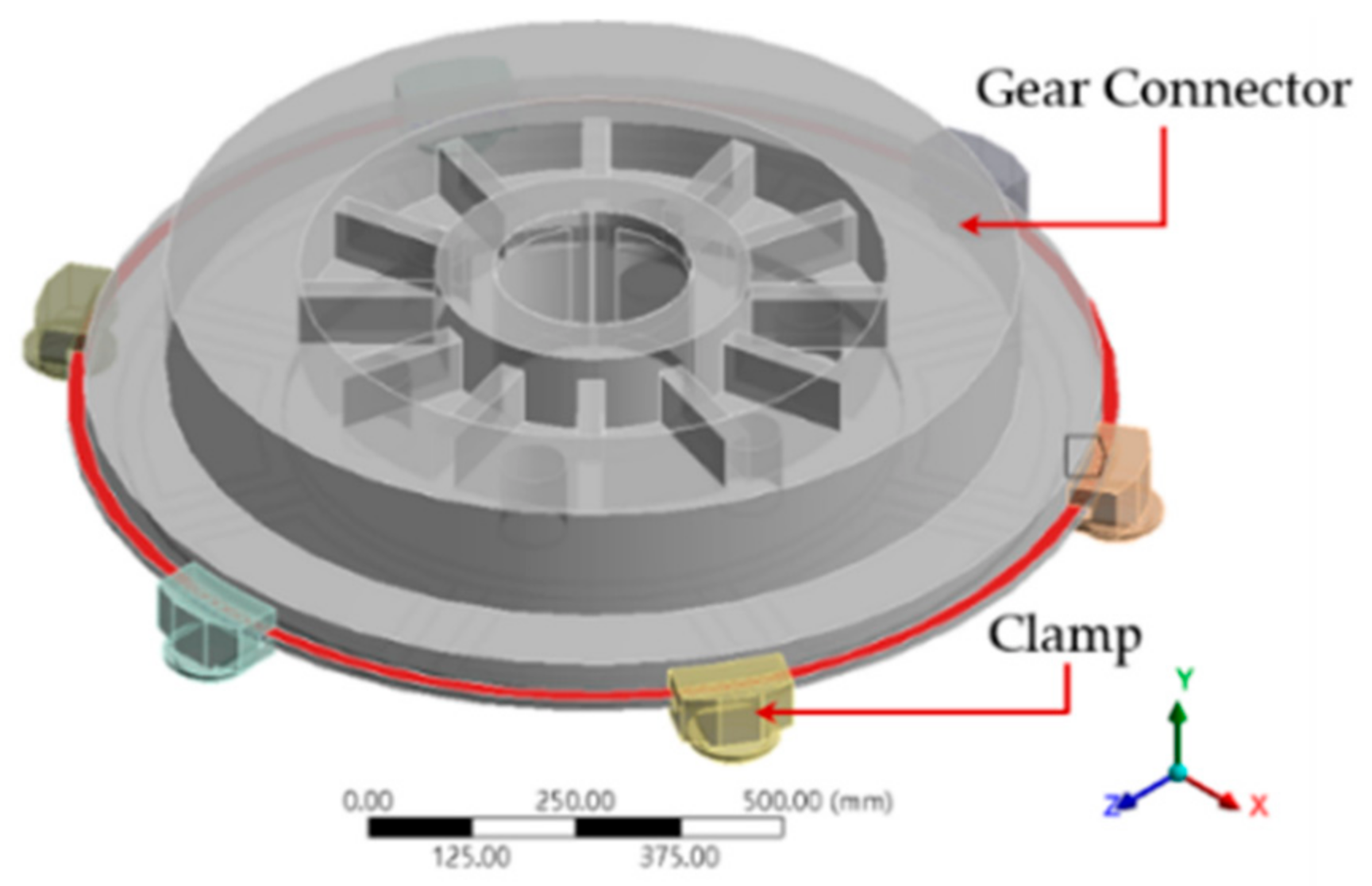
- The contact conditions of the gear connector and the small gears in the gearbox are shown in Figure 13. The frictional contact type was selected here. The contact between the clamp and the gear connector was frictional, as shown in Figure 14. The contact condition between the ball screw and the fixed guide rail was bonded, as shown in Figure 15.
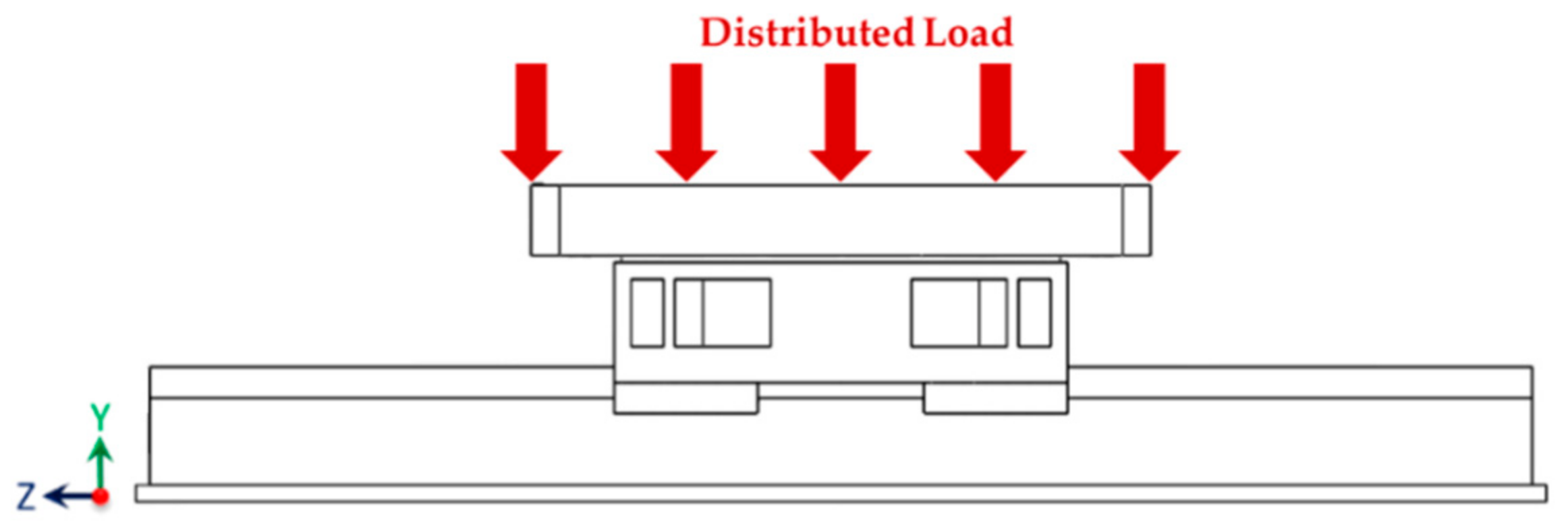
- The maximum external load utilized in this study consisted of the maximum axial workpiece weight of 117,682 N and the maximum axial specific drilling force of 9348 N.
3. Analysis Results
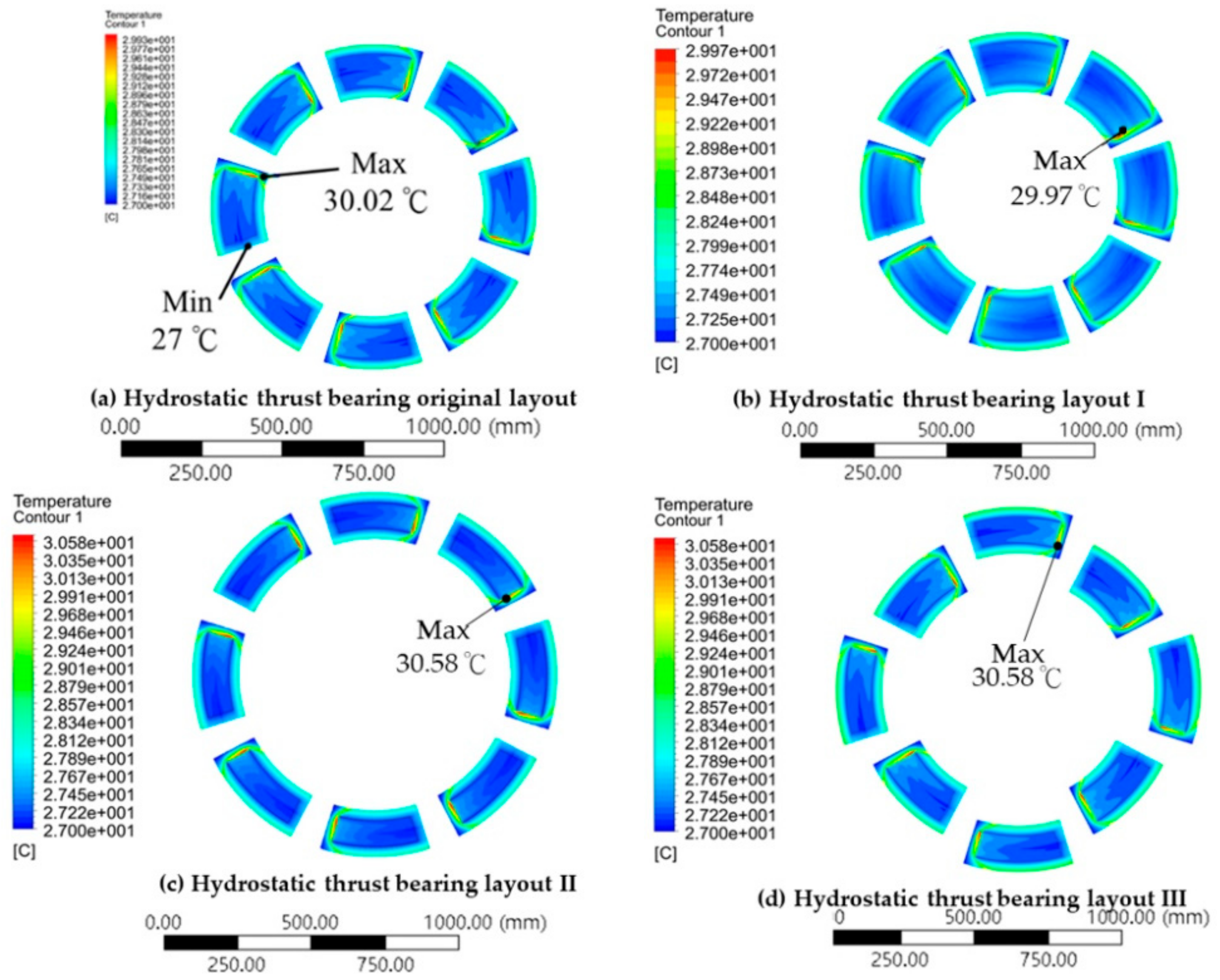
3.1. Simulation Results of the Oil Film Temperature Field of Different Hydrostatic Thrust Bearing Layouts
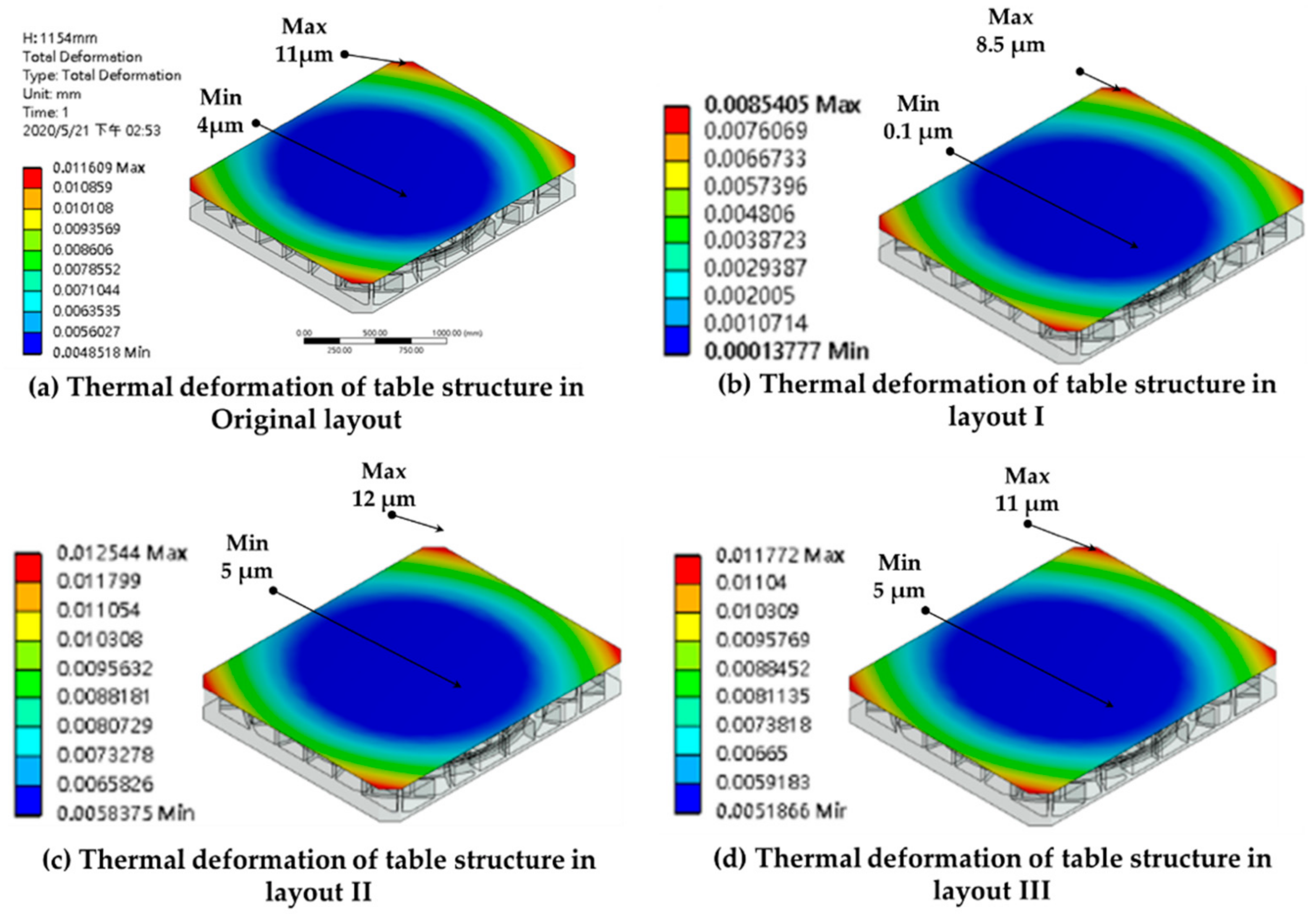
3.2. Simulation Results of the Thermal Deformation of Worktable from Different Hydrostatic Thrust Bearing Layouts
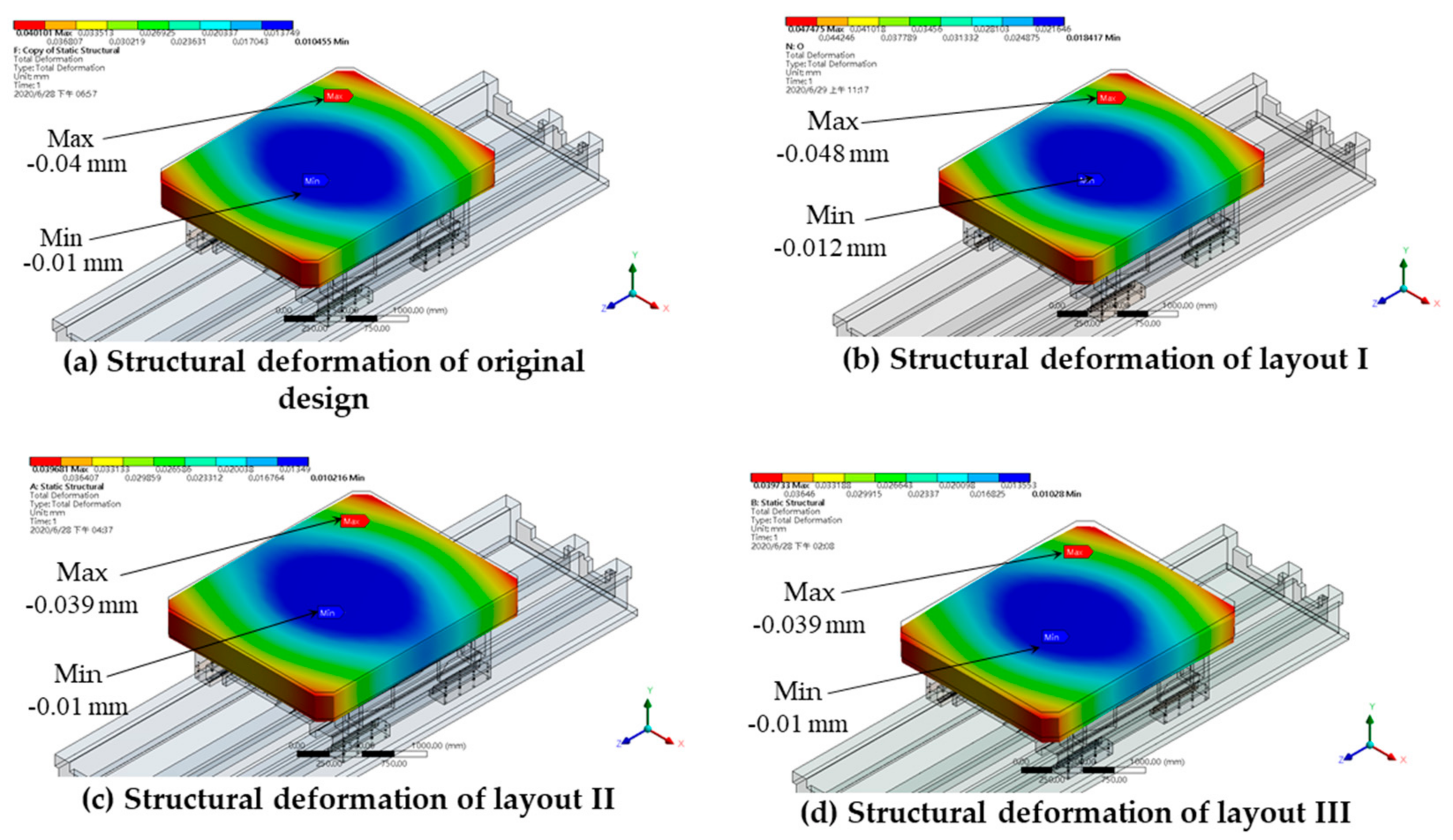
3.3. Simulation Results of the Structural Deformation of the Worktable Caused by an Evenly Distributed Load
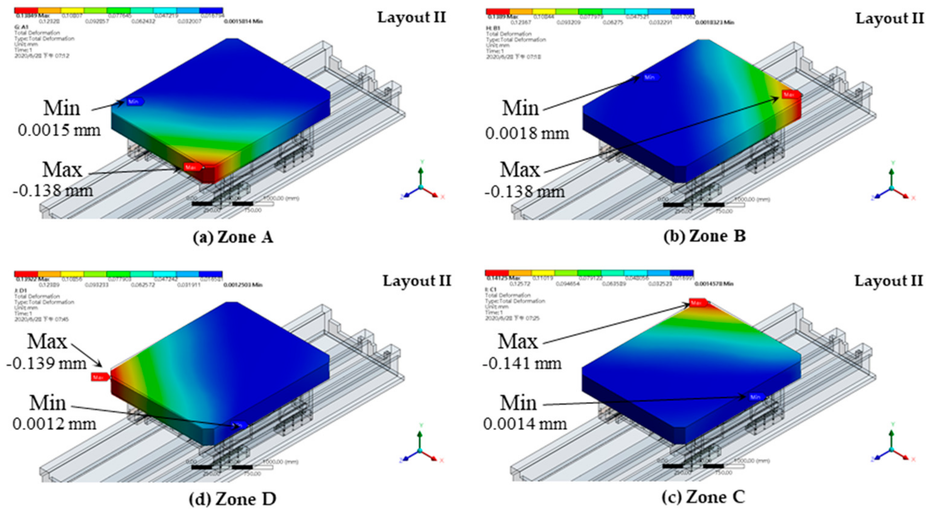
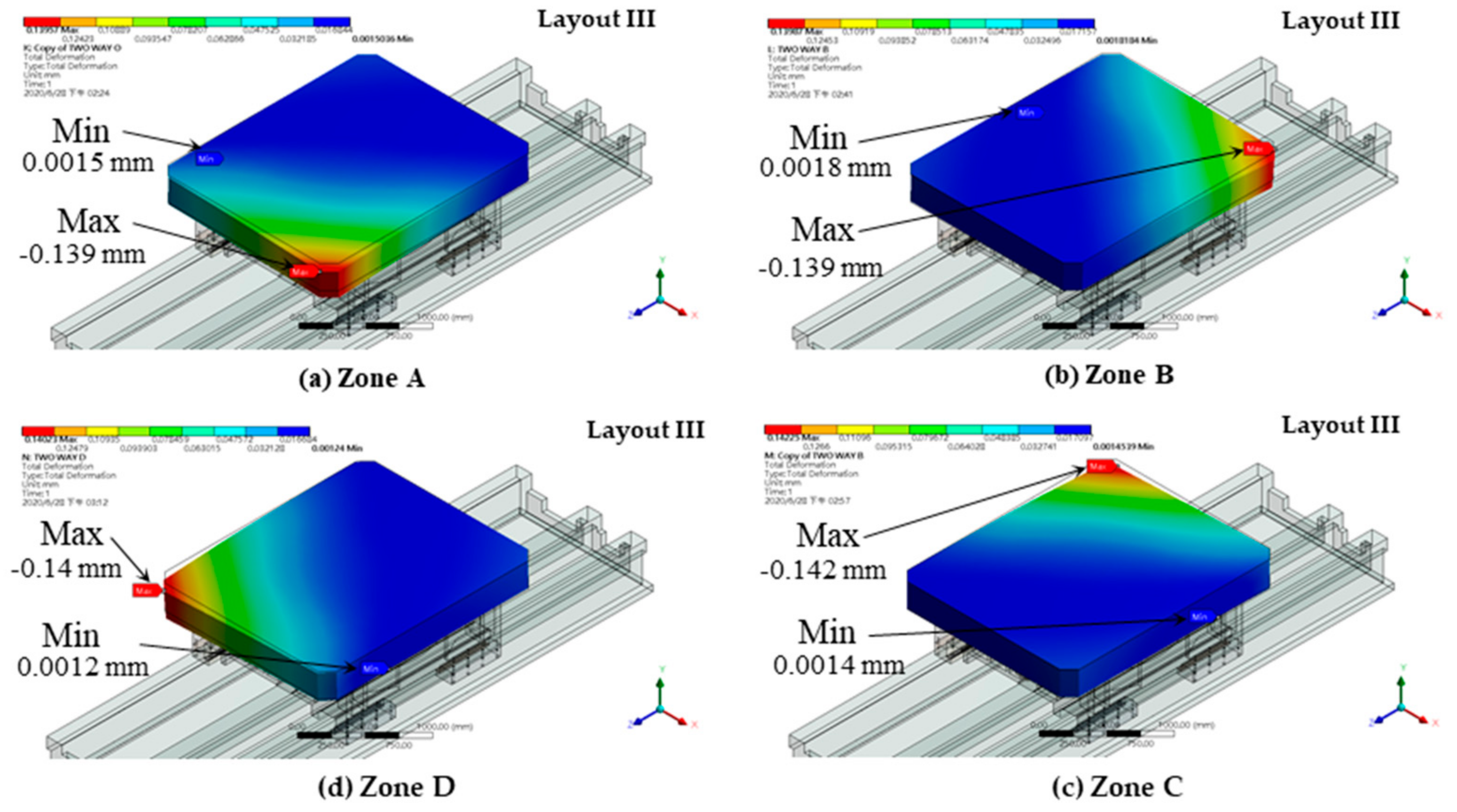
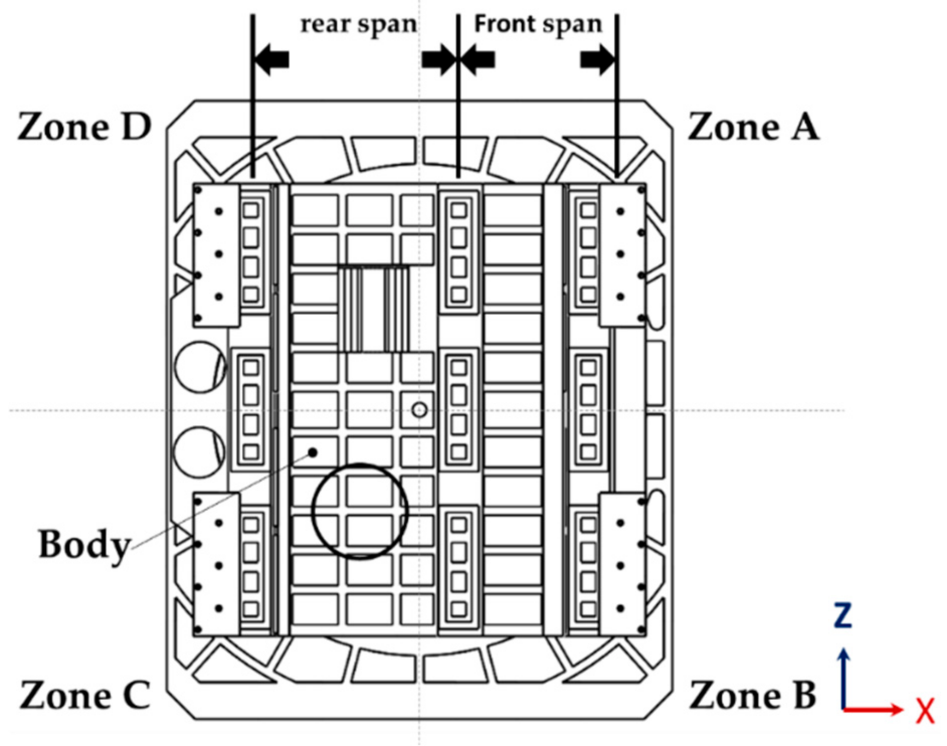
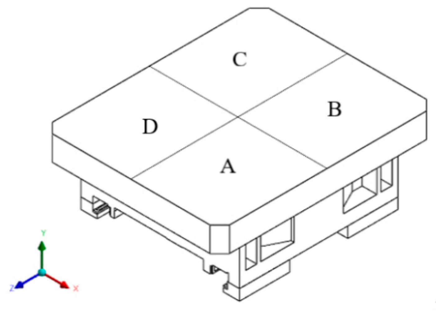
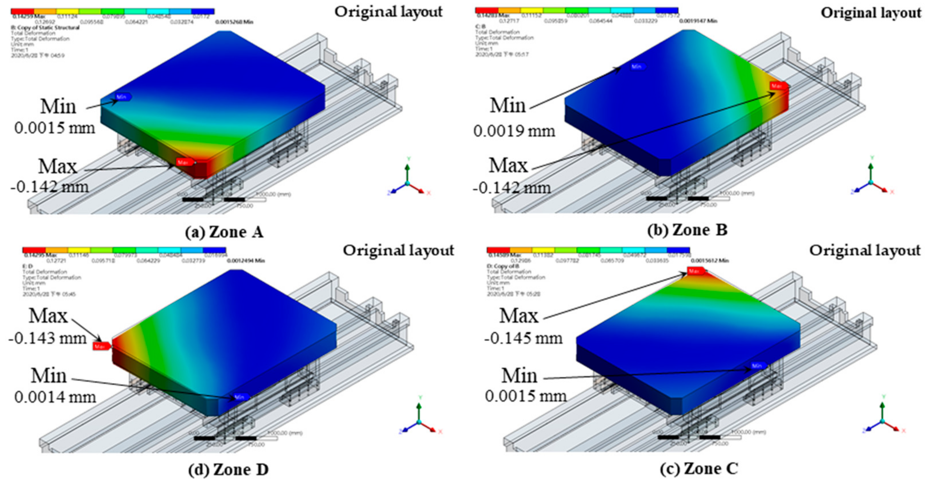
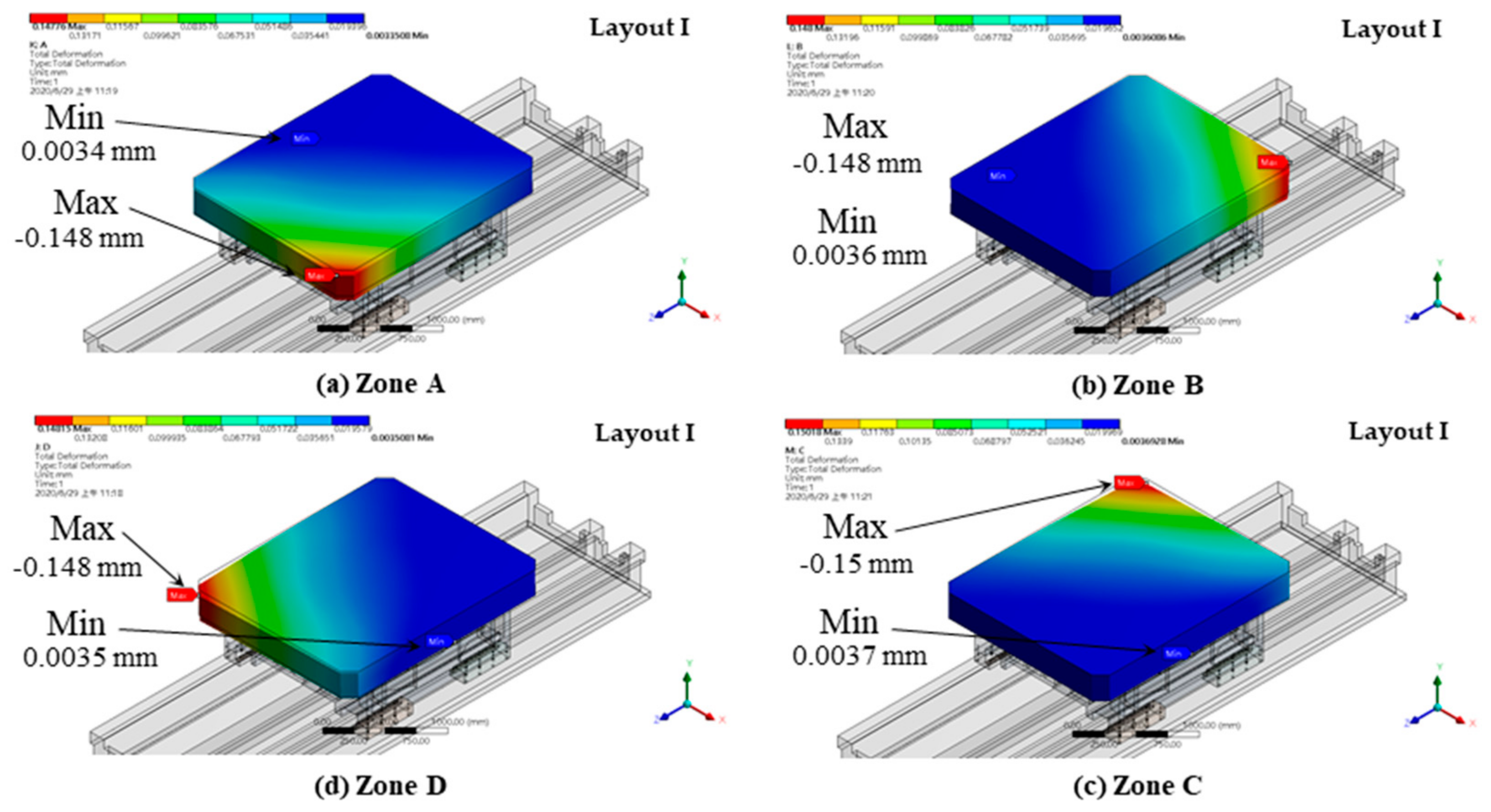
3.4. Simulation Results of the Structural Deformation of the Worktable Caused by an Eccentric Load
4. Analysis Results and Discussion
- Under the evenly distributed load and eccentric load conditions, Layout III had the smallest worktable deformation among the four layouts, while Layout I had the largest deformation under both conditions. These results show that the larger the recess layout diameter, the greater the recess’s resistance against the tilting moment, which reduced the structural deformation of the worktable.
- The thermal deformation caused by Layout II was the largest among the four layouts, while Layout I had the smallest thermal deformation.
- When the rotational speed of the rotary table was fixed, a hydrostatic thrust bearing recess placed farther away from the center of the worktable would experience a faster tangential speed, which increased the oil film temperature.
5. Conclusions
- The layout diameter of the hydrostatic thrust bearing recess has a significant effect on the worktable’s resistance against an eccentric load. A dual-ring recess layout offers better resistance against the tilting moment compared to a single-ring layout while, in single-ring layouts, a larger layout diameter offers better resistance against the tilting moment compared to a smaller layout diameter.
- If one chooses a recess layout based on the rotary table’s resistance against the tilting moment, the oil film temperature must also be taken into account, due to the reduced recess dimensions in a limited structural space. Moreover, the recess of a hydrostatic thrust bearing placed further away from the center of the worktable experiences a faster tangential speed, which increases the oil film temperature. In Layout II, eight recesses were placed within the range of the maximum layout diameter, which resulted in the largest thermal deformation of the worktable; in Layout III, only four recesses were placed within that range, which caused a medium thermal deformation; in Layout I, the minimum layout diameter was used, which resulted in the smallest thermal deformation.
Author Contributions
Funding
Institutional Review Board Statement
Informed Consent Statement
Data Availability Statement
Conflicts of Interest
Nomenclature
| Ae | effective area of recess | Ps | supply pressure |
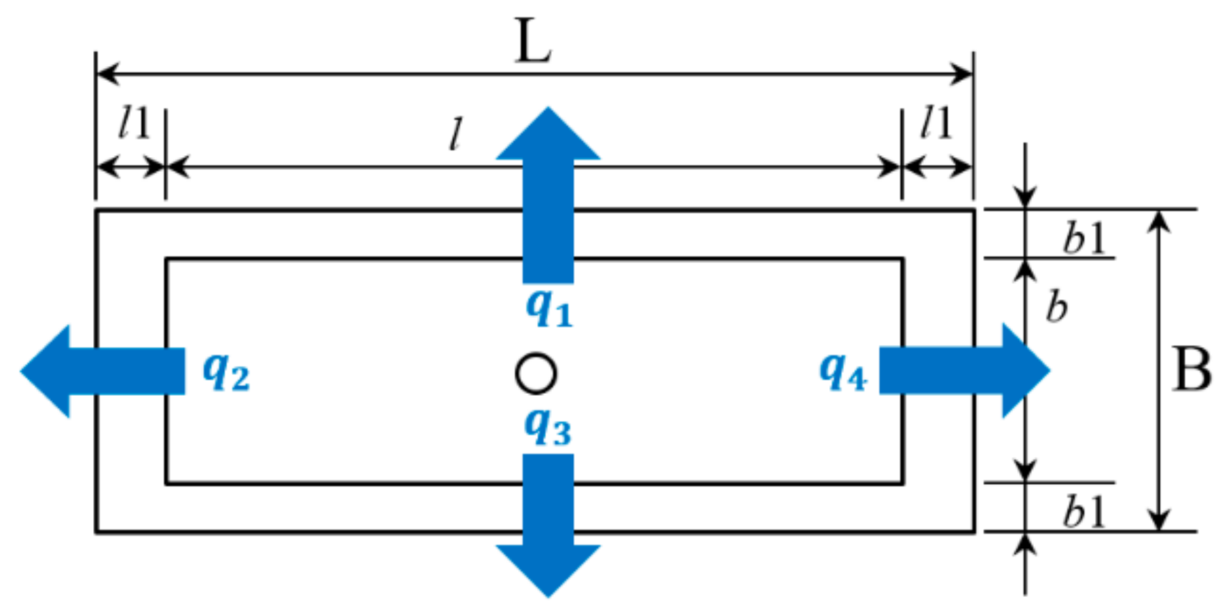
| B | width of bearing pad | Pr | recess pressure |
| b | width of recess | Qc0 | flow rate of capillary at designed film gap |
| b1 | sill of bearing pad in width direction | Qh0 | outlet flow rate of bearing sills designed film gap |
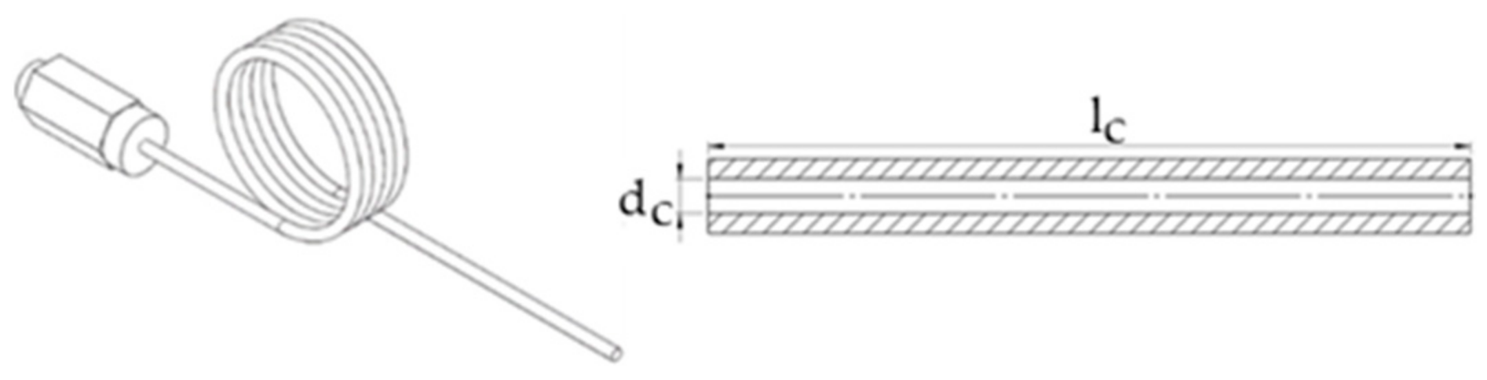
| dc | inner diameter of capillary | Qoutlet | outlet flow rate of the recess |
| e | eccentricity | Qinlet | inlet flow rate of the recess |
| ε | eccentricity rate | q1,2,3,4 | flow rate at sill 1, 2, 3, 4 |
| h0 | designed film gap | R1 | inner radius of the bearing pad |
| L | length of bearing pad | R2 | inner radius of the recess |
| l | length of recess | R3 | outer radius of the recess |
| l1 | sill of bearing pad in length direction | R4 | outer radius of the bearing pad |
| lc | length of capillary | Rc | flow resistance of the capillary |
| θ | angle of the recess | Rc0 | flow resistance of the capillary at designed film gap |
| μt | viscosity of the lubricant oil | Rho | flow resistance of the bearing sills at designed film gap |
| W | Load-carrying capacity of the bearing pad |
References
- Slocum, A.H. Precision Machine Design; Society of Manufacturing Engineers: Tripadvisor, MI, USA, 1992. [Google Scholar]
- Rowe, W.B. Hydrostatic and Hybrid Bearing Design; Butterworth: Oxford, UK, 1983. [Google Scholar]
- Bassani, R.; Piccigallo, B. Hydrostatic Lubrication; Elsevier: Amsterdam, The Netherlands, 1992. [Google Scholar]
- Harnoy, A. Bearing Design in Machinery: Engineering Tribology and Lubrication; CRC Press: Boca Raton, FL, USA, 2002. [Google Scholar]
- Rowe, W.B. Hydrostatic, Aerostatic and Hybrid Bearing Design; Butterworth-Heinemann: Oxford, UK, 2012. [Google Scholar]
- Lee, H.B.; Oh, J.H.; Oh, C.H.; Choi, Y.H. Structural Design Optimization of the Rotary Table of a Floor Type Boring Machine for Minimum Weight and Compliance by using GA. Appl. Mech. Mater. 2013, 271–272, 1421–1426. [Google Scholar] [CrossRef]
- Shie, J.S.; Shih, M.C. A Study on Optimum Design and Dynamic Behavior of a Hydrostatic Guideway on Rotary Machine Tool. In Proceedings of the 2013 CACS International Automatic Control Conference, Sun Moon Lake, Taiwan, 2–4 December 2013. [Google Scholar]
- Wang, S.; Du, X.; Li, M.; Cao, Z.; Wang, J. Analysis of Temperature effect on the Lubricating State of Hydrostatic Bearing. J. Theory Appl. Inf. Technol. 2013, 48, 817–821. [Google Scholar]
- Srinivasan, V. Analysis of Static and Dynamic Load on Hydrostatic Bearing with Variable Viscosity and Pressure. Int. J. Sci. Technol. 2013, 6, 4777–4782. [Google Scholar] [CrossRef]
- Zhao, J.; Liang, Y.; Gao, D. Oil Pocket’s Bearing Capacity Analysis of Liquid Hydrostatic Worktable in Gantry Moving Milling Center. Chin. J. Mech. Eng. 2014, 27, 1008–1017. [Google Scholar]
- Zhang, H. Research on the Application of Constant Pressure Closed Static Pressure Guideway for the Guideway of Heavy CNC Floor Milling and Boring Machine. Mech. Eng. 2016, 6, 133–134. (In Chinese) [Google Scholar] [CrossRef]
- Zhang, Y.; Liu, G.; Yang, X.; Hu, C.; Wang, H.; Shao, J. Coupled Solving Thermal Deformation of Hydrostatic Bearing Rotary Worktable Based on Temperature Fields of Oil Film. J. Comput. Theory Nanosc. 2015, 12, 3917–3921. [Google Scholar] [CrossRef]
- Wang, Y.; Zhao, Y.; Cai, L.; Liu, Z.; Cheng, Q. Effects of Thermal and Hydrodynamic Characteristics of Heavy-Duty Rotary Table on the Hydrostatic Circular Pads. J. Vibroeng. 2016, 18, 4193–4206. [Google Scholar]
- Wang, J.; Yin, Y.; Liu, Z. Study on Dynamic Characteristics of Oil Film of Hydrostatic Rotary Table Considering the Effect of Unbalance Load and Roughness. In Proceedings of the 2016 International Conference on Applied Mechanics, Mechanical and Materials Engineering (AMMME 2016), Xiamen, China, 18–19 December 2016. [Google Scholar]
- Wang, Y.; Liu, Z.; Cai, L.; Cheng, Q.; Dong, X. Optimization of Oil Pads on a Hydrostatic Turntable for Supporting Energy Conservation Based on Particle Swarm Optimization. J. Mech. Eng. 2018, 64, 95–104. [Google Scholar]
- Chang, J.H. The Study on Hydrostatic Bearing Design for the Table of Horizontal Boring Machine. Master’s Thesis, National Kaohsiung University of Science and Technology, Kaohsiung, Taiwan, 2018. [Google Scholar]
- Kettleborough, C.F. The Stepped Thrust Bearing—A Solution by Relaxation Methods. J. Appl. Mech. 1954, 21, 19–24. [Google Scholar] [CrossRef]
- Johnston, R.C.R.; Kettleborough, C.F. An Experimental Investigation into Stepped Thrust-Bearings. Proc. Inst. Mech. Eng. 1956, 170, 53–54. [Google Scholar] [CrossRef]
- Kettleborough, C.F. The Hydrodynamic Pocket Thrust-Bearing. Proc. Inst. Mech. Eng. 1956, 170, 55–56. [Google Scholar] [CrossRef]
- Kettleborough, C.F. The Tapered-Land Thrust Bearing. J. Appl. Mech. 1956, 23, 581–583. [Google Scholar] [CrossRef]
- Kettleborough, C.F. An Approximate Analytical Solution for the Stepped Bearing. J. Appl. Mech. 1961, 28, 507–510. [Google Scholar] [CrossRef]
- Hahn, E.J.; Kettleborough, C.F. Solution for the Pressure and Temperature in an Infinite Slider Bearing of Arbitrary Profile. J. Lubr. Technol. 1967, 89, 445–452. [Google Scholar] [CrossRef]
- Hahn, E.J.; Kettleborough, C.F. The effects of thermal expansion in infinitely wide slider bearings—Free thermal expansion. J. Lubr. Technol. 1968, 90, 233–239. [Google Scholar] [CrossRef]
- Hahn, E.J.; Kettleborough, C.F. Thermal Effects in Slider Bearings. Proc. Inst. Mech. Eng. 1968, 183, 53–55. [Google Scholar] [CrossRef]
- Kettleborough, C.F. Hydrodynamic Induced Vibrations in Accelerated Thrust Bearings. J. Mech. Eng. Sci. 1974, 16, 69–70. [Google Scholar] [CrossRef]
- Gohar, R.; Rahnejat, H. Fundamentals of Tribology, 3rd ed.; World Scientific: Singapore, 2018. [Google Scholar]
- Coombs, J.A.; Dowson, D. An Experimental Investigation of the Effects of Lubricant Inertia in a Hydrostatic Thrust Bearing. Proc. Inst. Mech. Eng. 1964, 179, 270–272. [Google Scholar] [CrossRef]
- Safar, Z.S. Adiabatic solution of a tilted hydrostatic thrust bearing. Wear 1983, 86, 133–138. [Google Scholar] [CrossRef]
- Yang, X.D.; Shao, J.P.; Xu, X.Q.; Wang, Y.F.; Yin, C.; Jiang, H. Research on Velocity Influence on Thermal Deformation Field of Heavy Hydrostatic Thrust Bearing. Adv. Mater. Res. 2010, 129–131, 968–972. [Google Scholar] [CrossRef]
- Li, X.; Wang, X.; Li, M.; Ma, Y.; Huang, Y. The research status and progress of heavy/ large hydrostatic thrust bearing. Adv. Mech. Eng. 2014, 6, 982584. [Google Scholar] [CrossRef]
- Yang, S.-H. Design and Performance Evaluation of a Hydrostatic Rotary Table for Horizontal Boring Machines. Master’s Thesis, National Kaohsiung University of Science and Technology, Kaohsiung, Taiwan, 2020. [Google Scholar]


| Size Position | Thrust Oil Recess |
|---|---|
| θ (deg) | 35 |
| R1 (mm) | 371 |
| R2 (mm) | 404 |
| R3 (mm) | 544 |
| R4 (mm) | 577 |
| Effective area (m2) | 0.045 |
| Recess depth (mm) | 2 |
| Dimension | Recess of Maximum Diameter | Recess of Minimum Diameter |
|---|---|---|
| θ (deg) | 35 | 35 |
| R1 (mm) | 459.5 | 371 |
| R2 (mm) | 492.5 | 404 |
| R3 (mm) | 581 | 515.85 |
| R4 (mm) | 614 | 548.85 |
| Effective area (m2) | 0.03619 | 0.03619 |
| Recess depth (mm) | 2 | 2 |
| Outlet Flow Rate | |
|---|---|
| Min. diameter recess | 1.290 × 10⁻⁵ m3/s |
| Max. diameter recess | 1.460 × 10⁻⁵ m3/s |
| Original recess | 1.106 × 10⁻⁵ m3/s |
| Max Oil Film Temperature | |
|---|---|
| Min diameter recess | 29.97 °C |
| Max diameter recess | 30.58 °C |
| Original oil recess | 30.02 °C |
| Layout | Layout I Deformation (mm) | Layout II Deformation (mm) | Layout III Deformation (mm) | ||||
|---|---|---|---|---|---|---|---|
| Eccen. Load | |||||||
| Zone | Min | Max | Min | Max | Min | Max | |
| A | 0.0034 | −0.148 | 0.0015 | −0.138 | 0.0015 | −0.139 | |
| B | 0.0036 | −0.148 | 0.0018 | −0.138 | 0.0018 | −0.139 | |
| C | 0.0037 | −0.150 | 0.0014 | −0.142 | 0.0014 | −0.141 | |
| D | 0.0035 | −0.148 | 0.0012 | −0.139 | 0.0012 | −0.140 | |
| Maximum Deformation | |
|---|---|
| Layout I | −0.150 mm |
| Layout II | −0.142 mm |
| Layout III | −0.141 mm |
| Original layout | −0.145 mm |
Publisher’s Note: MDPI stays neutral with regard to jurisdictional claims in published maps and institutional affiliations. |
© 2022 by the authors. Licensee MDPI, Basel, Switzerland. This article is an open access article distributed under the terms and conditions of the Creative Commons Attribution (CC BY) license (https://creativecommons.org/licenses/by/4.0/).
Share and Cite
Huang, H.-C.; Yang, S.-H. Thrust-Bearing Layout Design of a Large-Sized Hydrostatic Rotary Table to Withstand Eccentric Loads for Horizontal Boring Machine Applications. Lubricants 2022, 10, 49. https://doi.org/10.3390/lubricants10040049
Huang H-C, Yang S-H. Thrust-Bearing Layout Design of a Large-Sized Hydrostatic Rotary Table to Withstand Eccentric Loads for Horizontal Boring Machine Applications. Lubricants. 2022; 10(4):49. https://doi.org/10.3390/lubricants10040049
Chicago/Turabian StyleHuang, Hua-Chih, and Shen-Hen Yang. 2022. "Thrust-Bearing Layout Design of a Large-Sized Hydrostatic Rotary Table to Withstand Eccentric Loads for Horizontal Boring Machine Applications" Lubricants 10, no. 4: 49. https://doi.org/10.3390/lubricants10040049
APA StyleHuang, H.-C., & Yang, S.-H. (2022). Thrust-Bearing Layout Design of a Large-Sized Hydrostatic Rotary Table to Withstand Eccentric Loads for Horizontal Boring Machine Applications. Lubricants, 10(4), 49. https://doi.org/10.3390/lubricants10040049