Article

Comparative Analysis of Rub-Impact Dynamics of Shrouded Blades Based on the Bilinear Hysteresis Model and the Coulomb Friction Model

1
Shaanxi Engineering Laboratory for Transmissions and Controls, Northwestern Polytechnical University, Xi’an 710071, China
2
AVIC The First Aircraft Institute, Xi’an 710089, China
3
School of Mechanics and Safety Engineering, Zhengzhou University, Zhengzhou 450001, China
*
Authors to whom correspondence should be addressed.
Lubricants 2022, 10(2), 31; https://doi.org/10.3390/lubricants10020031
Submission received: 16 December 2021 / Revised: 15 February 2022 / Accepted: 17 February 2022 / Published: 20 February 2022
(This article belongs to the Special Issue Friction and Wear in Machine Design)

Abstract

:
The bilinear hysteresis friction model and the Coulomb friction model are two typical macro slip models which are widely used by researchers in simulation analysis of rub-impact dynamics of shrouded blades. However, differences in the simulation results of shrouded blades based on these two friction models have not well been studied recently. In this paper, a two-dimensional lumped mass model of shrouded blades including axial displacements and tangential displacements is established, and the kinetic equations of the blades under different contact conditions are derived. The contact-separation and stick-slip transition points are determined by the bisection method. Using the fourth-order Runge–Kutta method, comparative analysis of the nonlinear characteristics and the vibration reduction characteristics of shrouded blades based on the bilinear hysteresis friction model and the Coulomb friction model are carried out. Numerical simulation results indicate that the nonlinear characteristics and the vibration reduction characteristics of shrouded blades based on these two friction models are not accordant. The discussion in this paper offers thinking for the selection of the friction model in a study on rub-impact dynamics of shrouded blades.

1. Introduction

Damping is very important in the manufacturing of Integrally Bladed Rotors, as illustrated in [1,2,3,4]. Meanwhile, in the service life of turbine blades damping design is also a key operation, as high cycle fatigue failures may occur due to high vibratory stresses. The shroud device is actually an effective dry friction damper that is insensitive to temperature, simple in structure and has been widely used to reduce the vibration of turbine blades [1,5,6]. The rub-impact dynamics of shrouded blades is the focus of this research field, in which selection of the friction model is very important because it partly determines the accuracy of the prediction of the blade response. In recent studies, the Coulomb friction model and the bilinear hysteresis model are mainly used as two typical macro slip friction models which are suitable for modeling point to surface dry friction contact. The micro slip friction model which is suitable for modeling surface to surface dry friction contact has been proposed, but it should be pointed out that the micro slip model is basically based on the bilinear hysteresis model. In this paper, studies on the rub-impact dynamics of shrouded blades with the two typical macro slip models are summarized as follows.
Studies using the Coulomb friction model: Yang et al. [7] studied the stick-slip friction phenomenon with the Coulomb friction model and predicted the resonant response of a two-degree-of-freedom oscillator constrained by friction with the harmonic balance method (HBM). Xia [8] set up a model to discuss the stick-slip motion of a two-dimensional oscillator with the Coulomb friction model and a numerical method was adopted. Allara [9] described different models for the friction contact of non-spherical geometries and studied the dissipated energy of different contact geometries with different models. In [10], different contact models were proposed using the finite element method and these models were compared to predict the nonlinear dynamic behavior of blades. In [11], the impact vibration of aeroengine shrouded blades under a multiple-harmonic excitation was studied by employing the Galerkin method, and an approximate analytical solution of the responses of the shrouded blades was obtained with the Fourier series method. With the HBM, Wang and Zhang [12] analyzed the forced responses of a dry friction oscillator based on the Iwan model. Considering the contact stiffness of the contact surface, Zucca and Firrone [13] investigated the performances of HBM by comparing the uncoupled approach to a fully coupled static/dynamic approach. Roberta and Rubens [14] adopted the spring mass model, and stick and slip modes are considered along with a non-smooth transition between them. In [15], the steady-state response of the dry friction damping system was solved by the multi-harmonic balance method and the alternating time/frequency domain strategy is integrated for evaluating the nonlinear force and pertinent stiffness.
Studies using the bilinear hysteresis model: Popp [16] discussed the influence of friction contact on the structural stiffness and the expected damping ratio, and performed experimental tests based on the theoretical model under different frictional contact samples’ structures. Petrov [17] developed an effective method to analyze the periodic forced response of nonlinear cyclically symmetric structures, which used the periodic sector model to calculate the multi-harmonic forced response of the whole blade disk without any loss in accuracy in calculations and modeling. Qi [18] established the macro-micro model to analyze the vibration response of the dry friction damping systems and used the bilinear hysteresis model to analyze the macro-micro model. In [19], a decrease in vibrational amplitudes was explained by changes of boundary conditions induced by a stick/slip behavior. The contributions of respective energy dissipation and the change of contact state on peak levels were showed. Fu and Lu [20] studied the influences of the gap between adjacent shrouds, the amplitude of the external force, the width, thickness and length of the blade on the nonlinear dynamical responses of the blades. In [21], the nonlinear dynamic responses of the rotating blade are obtained and the shock and vibration mechanism of the shrouded blade was revealed, the relationship between vibration suppression and structure parameters of the blade shroud was studied. In [22], the vibration impact mechanism of a rotating shrouded blade with asymmetric clearance was investigated, and the influence of the initial gap between two adjacent shrouds on the vibration amplitude was obtained. Pešek et al. [23] studied the effect of friction in blade shrouds under appropriate frequency harmonic excitation and subsequent free vibration attenuation. The experimental results agreed well with the numerical results. In [24], an analytical expression was formulated to compute the Jacobian matrix for 3D friction contact modeling. The developed expression has been successfully used for the calculation of the friction damping on a turbine blade with a shroud contact interface having an arbitrary 3D relative displacement. Considering the effects of the centrifugal stiffening and the spin softening of the blade, Ma et al. [25] established a dynamic model of rotating shrouded blades. He et al. [26] studied stick-slip-separation transition boundary conditions and the nonlinear dynamics of shrouded blades, the vibration response is calculated using Runge–Kutta algorithm. Botto and Umer [27] developed a novel experimental test rig to extensively investigate the dry friction damper dynamic behavior. In [28], the mechanism of a complex bifurcation behavior caused by flight maneuvers in an aircraft rub-impact rotor system with Duffing type non-linearity was discussed, which provided deep insight into the mechanism of the complex nonlinear phenomenon induced by the constant excitation. Yang et al. [29] investigated the influence of the parametric uncertainties on the dynamic characteristics of a rotor-blade system. He et al. [30,31] studied the influence of the convective inertial force and Coriolis inertial force on the vibration reduction of dry friction damped blades considering the rotation of the bladed disc.
Recent studies have not fully dealt with the difference of simulation results based on the two typical macro slip models. In this paper, a comparative analysis of the nonlinear characteristics and the vibration reduction characteristics of shrouded blades based on the two typical macro slip models was carried out and the differences between two kinds of simulation results can be found. It is also meaningful for the improvement of the micro slip model. In order to explore the influence of the two different friction models on the simulation results of the system response, the following work has been carried out. As the main work of this paper is mechanism research, the mass-spring model which has higher computational efficiency is adopted and a two-dimensional lumped mass model including axial displacements and tangential displacements of shrouded blades is established. The impact force is simulated by a linear spring and the friction force is simulated by the bilinear hysteresis model and the Coulomb friction model, respectively. The kinetic equations and the stick-slip transition boundary conditions of the blades under different contact conditions are all derived and a fourth-order Runge–Kutta algorithm is presented to predict the system response. Since the change of normal load requires a higher step size of the Runge–Kutta algorithm, the capture of stick-slip and contact-separation transition points is very important and can be completed by the bisection method with a variable step size. With the two different friction models, the influences of stiffness ratio, initial gap and amplitude of excitation force on the nonlinear characteristics and vibration reduction characteristics of the shrouded blades are studied and compared.

2. Rub-Impact Dynamic Modeling Based on the Coulomb Friction Model and the Bilinear Hysteresis Model

In the aero-engine, all the shrouded blades are set up in a circle which can be considered as a symmetric structure. In order to simplify the dynamic model, two adjacent shrouded blades are selected and the structure of the blades discussed in this paper is shown in Figure 1, where the x y z orthogonal coordinate system attached to the bladed disc is defined with three orthogonal directions, namely tangential direction ( x ), axial direction ( y ), and radial direction ( z ).

2.1. Rub-Impact Dynamic Model and Equations
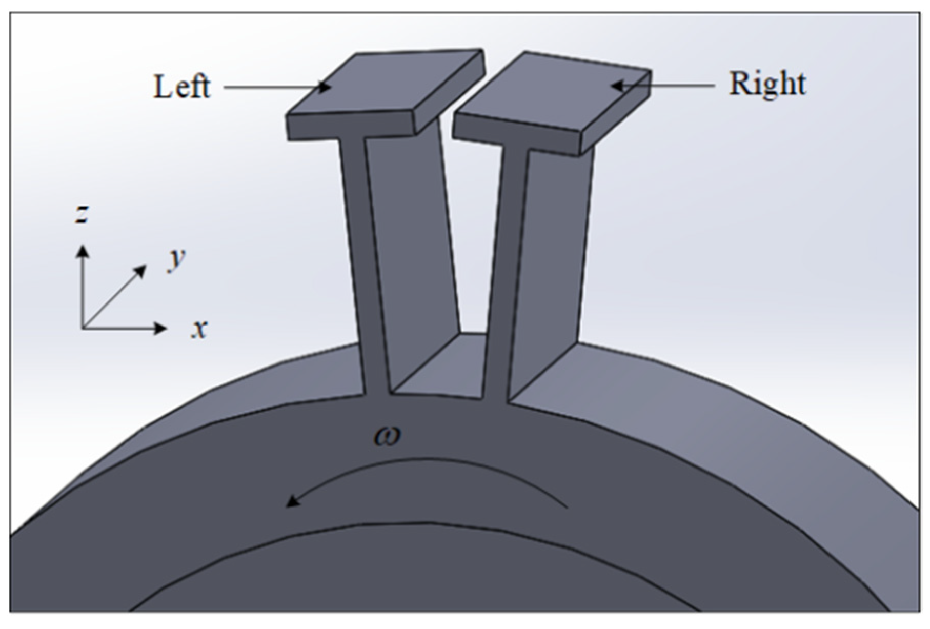
As shown in Figure 1, in the working condition of the turbine blades, the blades will undergo contact-separation transition and stick-slip transition due to the bending vibration in both x and y directions. In the contact state, the impact and dry friction occurs in the contact surface. In engineering practice, the shrouded blades vibrate in a three-dimensional direction which is very complicated. In this paper, the bending vibration of the blade in x direction and y direction is discussed, while the bending vibration in z direction, which is very small in comparison to that in x and y direction, and the torsional vibration is not considered for simplicity. Based on the analysis above, a spring-mass model of the structure in 
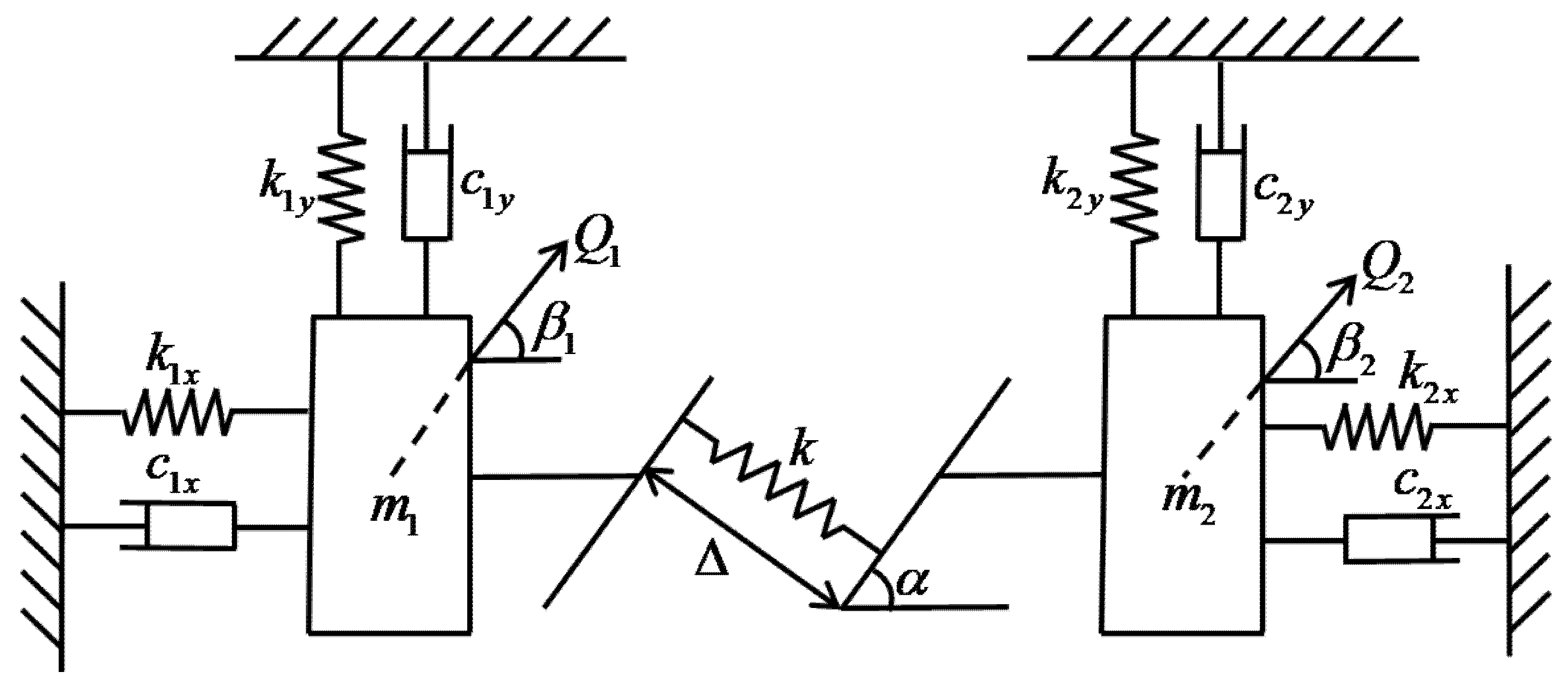
Figure 1 can be set up and shown in Figure 2.
When the initial gap Δ is negative, a preload is applied between the two shrouds, otherwise, there is a certain initial distance between the two shrouds.
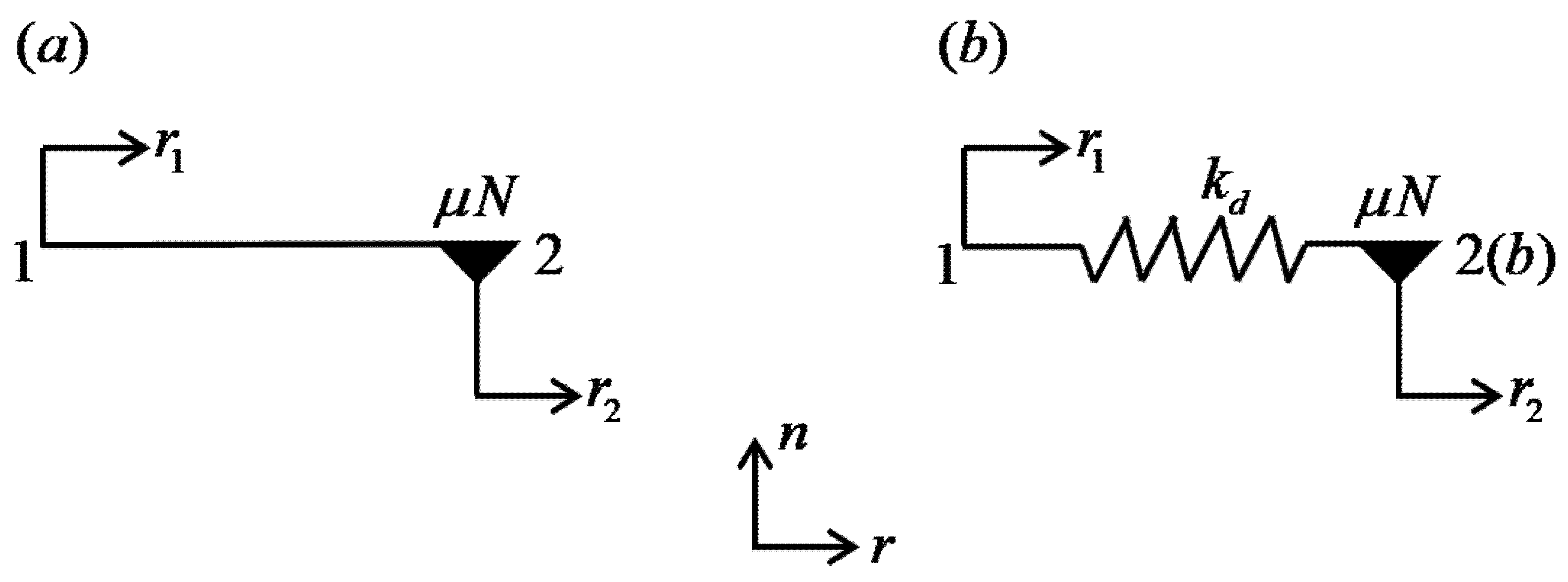
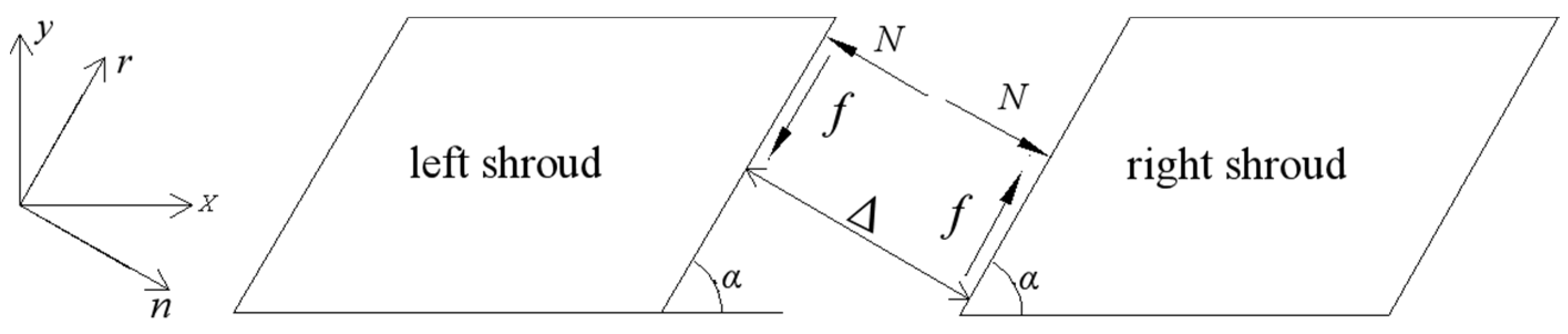
The dry friction and impact between the two shrouds are shown in Figure 3, which are very complex in the process of the vibration of the blades. As the torsional vibration is not considered, the contact of two blades is face to face. The direction r is tangential to the contact, while the direction n is normal to the contact. The relation motion in r and n direction will lead to stick-slip transition and contact-separation transition separately.
In the process of the vibration of the two blades, there are two stages: the separation stage and the contact stage in which stick-slip transition occurs. To analyze the normal load and friction force, displacements of blades in x and y directions can be projected into r and n directions. Then the displacements of shrouded blades in r and n directions can be written as:
{ r 1 = x 1 cos α + y 1 sin α ,   n 1 = x 1 sin α y 1 cos α r 2 = x 2 cos α + y 2 sin α ,   n 2 = x 2 sin α y 2 cos α
In Equation (1), r 1 and r 2 denote the displacements of the left and the right shroud in r direction, while n 1 and n 2 denote the displacements of the left and the right shroud in n direction.
According to Figure 2 and Figure 3, kinetic equations of the blades can be written as:
{ m 1 x ¨ 1 + c 1 x x ˙ 1 + k 1 x x 1 = Q 1 cos β N ( t , x 1 x 2 , y 1 y 2 , Δ ) sin α f cos α m 1 y ¨ 1 + c 1 y y ˙ 1 + k 1 y y 1 = Q 1 sin β + N ( t , x 1 x 2 , y 1 y 2 , Δ ) cos α f sin α m 2 x ¨ 2 + c 2 x x ˙ 2 + k 2 x x 2 = Q 2 cos β + N ( t , x 1 x 2 , y 1 y 2 , Δ ) sin α + f cos α m 2 y ¨ 2 + c 2 y y ˙ 2 + k 2 y y 2 = Q 2 sin β N ( t , x 1 x 2 , y 1 y 2 , Δ ) cos α + f sin α
Due to the symmetry characteristics of the shrouded blades, some parameters of the two blades are consistent. So: m 1 = m 2 = m , c 1 x = c 2 x = c x , c 1 y = c 2 y = c y , k 1 x = k 2 x = k x , k 1 y = k 2 y = k y , Q 1 = F 0 sin ( ω t + φ 1 ) , Q 2 = F 0 sin ( ω t + φ 2 ) . Equation (2) can be expressed as:
{ m x ¨ 1 + c x x ˙ 1 + k x x 1 = Q 1 cos β N sin α f cos α m y ¨ 1 + c y y ˙ 1 + k y y 1 = Q 1 sin β + N cos α f sin α m x ¨ 2 + c x x ˙ 2 + k x x 2 = Q 2 cos β + N sin α + f cos α m y ¨ 2 + c y y ˙ 2 + k y y 2 = Q 2 sin β N cos α + f sin α
The normal load is simulated by a linear spring with its stiffness of k and can be described as Equation (4).
N = { 0 ( n 1 n 2 Δ < 0 ) k ( n 1 n 2 Δ ) ( n 1 n 2 Δ 0 )
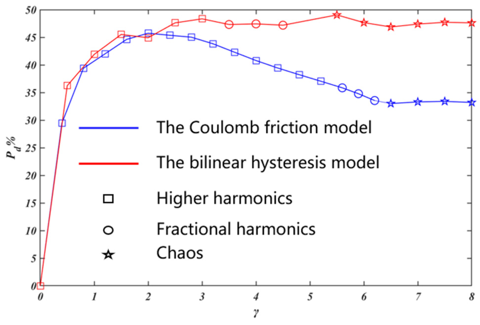
Accordingly, the bilinear hysteresis model and the Coulomb friction model which are shown in Figure 4 are introduced separately to simulate the friction force f . In order to simplify the calculation, the difference of kinetic and static friction coefficients is not considered in this paper. Thus, the friction coefficient is denoted as μ .
In Figure 4a, the Coulomb friction model is introduced. With the Coulomb friction model, points 1 and 2 are always attached to the left shroud and the right shroud, respectively. In contrast with the bilinear hysteresis model, the elastic deformation is not considered in the Coulomb friction model, and the viscous state of the contact surface is actually a relatively static state. In this paper, as described in reference [26], an error limit is given for the relative velocity and the stuck state of the contact surface is studied.
(1) When r ˙ 1 r ˙ 2 = 0 , points 1 and 2 remain relatively static, Equations (5) and (6) can be obtained.
( x ˙ 1 x ˙ 2 ) cos α + ( y ˙ 1 y ˙ 2 ) sin α = 0
( x ¨ 1 x ¨ 2 ) cos α + ( y ¨ 1 y ¨ 2 ) sin α = 0
Performing a linear operation on formulas in Equation (3), Equations (7) and (8) are derived.
m ( x ¨ 1 x ¨ 2 ) cos α + c x ( x ˙ 1 x ˙ 2 ) cos α + k x ( x 1 x 2 ) cos α = ( Q 1 Q 2 ) cos α cos β 2 N sin α cos α 2 f cos 2 α
m ( y ¨ 1 y ¨ 2 ) sin α + c y ( y ˙ 1 y ˙ 2 ) sin α + k y ( y 1 y 2 ) sin α = ( Q 1 Q 2 ) sin α sin β + 2 N sin α cos α 2 f sin 2 α
Based on Equations (5)–(8), Equation (9) can be obtained.
f = 1 2 [ ( Q 1 Q 2 ) ( cos α cos β + sin α sin β ) c x ( x ˙ 1 x ˙ 2 ) cos α c y ( y ˙ 1 y ˙ 2 ) sin α k x ( x 1 x 2 ) cos α k y ( y 1 y 2 ) sin α ]
If f μ N , the friction force f is calculated by Equation (9).
Otherwise, f equals to μ N and reverses its direction.
(2) If r ˙ 1 r ˙ 2 0 , relative slipping occurs at the contact interface, the value of the sliding friction force equals μ N .
In Figure 4b, the bilinear hysteresis model is introduced and the friction force is simulated by a spring with a finite contact stiffness k d . The spring has no initial length and can yield. Points 1 and 2 are attached to the left shroud and the right shroud, respectively, at all times. Point b is the sliding contact point that can slide relative to point 2. Initially, Points 1, 2 and b coincide with each other, and point b is attached to point 2 with a limiting friction force. The displacements of the left and the right shroud in r direction are denoted by r 1 and r 2 , respectively, while that of the sliding contact b relative to the bladed disc is denoted by r b . With two shrouds moving, point b keeps static with the right shroud when | r 1 r b | is less than μ N / k d and keeps static with the left shroud when the distance of the point 1 and b is equal to μ N / k d . The friction force can be determined by Equation (11), and the key to friction calculation is to trace the position of point b .
f = k d ( r 1 r b )

2.2. The Nondimensionalization of the Kinetic Equations

To analyze the nonlinear dynamics of the system conveniently, the nondimensionalization can be introduced as follows.
Denote ω x 2 = k x m , ω y 2 = k y m , ε 1 = c x 2 m ω x , ε 2 = c y 2 m ω y , X 1 = x 1 Δ , X 2 = x 2 Δ , Y 1 = y 1 Δ , Y 2 = y 2 Δ , τ = ω t , ( · ) = d · d τ , ( · ) = d 2 · d τ 2 , f x ¯ = f m Δ ω x 2 , f y ¯ = f m Δ ω y 2 , Q 1 x ¯ = Q 1 cos β m Δ ω x 2 , Q 1 y ¯ = Q 1 sin β m Δ ω y 2 , Q 2 x ¯ = Q 2 cos β m Δ ω x 2 , Q 2 y ¯ = Q 2 sin β m Δ ω y 2 , N x ¯ = N m Δ ω x 2 , N y ¯ = N m Δ ω Y 2 .
So, Equation (3) can be rewritten as Equation (11).
{ X 1 + 2 ε 1 X 1 + X 1 = Q 1 x ¯ N x ¯ sin α f x ¯ cos α Y 1 + 2 ε 2 Y 1 + Y 1 = Q 1 y ¯ + N y ¯ cos α f y ¯ sin α X 2 + 2 ε 1 X 2 + X 2 = Q 2 x ¯ + N x ¯ sin α + f x ¯ cos α Y 2 + 2 ε 2 Y 2 + Y 2 = Q 2 y ¯ N y ¯ cos α + f y ¯ sin α

3. Comparative Analysis of Dynamic Characteristics of the System with the Two Friction Models

3.1. Comparative Analysis of the Nonlinear Characteristics of the System

Based on the two-dimensional kinetic model and the above-derived equations of the shrouded blades, the transition points of the stick-slip and contact-separation are both captured by the bisection method to suppress the errors. Then a numerical integration scheme implementing a fourth-order Runge–Kutta algorithm with variable step is set up by using the two friction models separately. Combined with the time history, frequency spectrum, Poincare map and phase diagram, the nonlinear characteristics of the system are analyzed. In this section, with the two friction models, a comparative analysis of influences of different parameters including the stiffness ratio, the initial gap and amplitude of external excitation on the nonlinear characteristics of the system is carried out.
For the simulation study, as the dynamic characteristics of both the left blade and the right blade are the same, the simulation results of the left blade under different parameters are displayed and analyzed. According to reference [26], the basic parameters of the system are shown in Table 1 and specific parameters are given in the corresponding section. Denote Q 1 = F 0 sin ( ω t + φ 1 ) , Q 2 = F 0 sin ( ω t + φ 2 ) , f e = ω / 2 π .

3.1.1. The Influence of the Stiffness Ratio γ on the Nonlinear Characteristics of the System

The stiffness ratio is denoted by γ = k / k x . The specific parameters needed are shown in Table 2. The simulation results are shown in Figure 5, Figure 6, Figure 7 and Figure 8.
Figure 5 and Figure 6 separately show the bifurcation diagram of X 1 versus γ with the Coulomb friction model and the bilinear hysteresis model. Comparing Figure 5 with Figure 6, the bifurcation phenomenon occurs in different stiffness ratios and the bifurcation characteristics of the system are different with the increase of γ .
Figure 7 and Figure 8 illustrates Figure 5 and Figure 6 separately. In Figure 7a and Figure 8a, when γ = 1 , there is only one point in the Poincare map and only high-order harmonics exist in the frequency spectrum. The motions are both period-1 motions whose minimum period is equal to that of the external force. Comparing Figure 7b with Figure 8b, with the Coulomb friction model (Figure 7b, γ = 5.3 ), there are two points in the Poincare map and fractional frequencies ( f e / 2 , f e ) exist in the frequency spectrum, period-2 motion occurs and the minimum period is twice of that of the external force; with the bilinear hysteresis model (Figure 8b, γ = 4 ), period-3 motion occurs and the minimum period is three times of that of the external force. In Figure 7c and Figure 8c, when γ is further increased to 8, there are a lot of points in disorder in the Poincare map, the frequency spectrum becomes continuous, and chaos both occurs with the two friction models.

3.1.2. The Influence of the Initial Gap Δ on the Nonlinear Characteristics of the System

The specific parameters are displayed in Table 3. The simulation results are shown in Figure 9, Figure 10, Figure 11 and Figure 12.
The bifurcation diagram of X 1 versus Δ with the Coulomb friction model and the bilinear hysteresis model is shown in Figure 9 and Figure 10, respectively. Based on the comparison of the two Figures, as Δ increases bifurcation phenomenon occurs with different initial gaps and the bifurcation characteristics of the system are not consistent.
In Figure 11a and Figure 12a, when Δ = 1 × 10 5 m , chaos occurs in both of the two friction models. Comparing Figure 11b with Figure 12b, based on the Coulomb friction model (Figure 11b, Δ = 6 × 10 5 m ), the motion is period-4 motion whose minimum period is four times of the external force; based on the bilinear hysteresis model (Figure 12b, Δ = 3 × 10 5 m ), period-3 motion occurs and the minimum period is three times of that of the external force. In Figure 11c and Figure 12c, when Δ = 2.5 × 10 4 m , the motions are both period-1 motion.

3.1.3. The Influence of the Amplitude of Excitation Force F 0 on the Nonlinear Characteristics of the System

The specific parameters are summarized in Table 4 and the simulation results are shown in Figure 13, Figure 14, Figure 15 and Figure 16.
Figure 13 and Figure 14 separately show the bifurcation diagram of X 1 versus F 0 with the Coulomb friction model and the bilinear hysteresis model. Comparing the two Figures, the bifurcation phenomenon occurs at different values of the excitation force amplitude and it shows different bifurcation characteristics with the increase of F 0 .
Figure 15 and Figure 16 illustrate Figure 13 and Figure 14. In Figure 15a and Figure 16a, when F 0 = 5 N , the motions are period-1 motion in both of these two friction models. Comparing Figure 15b with Figure 16b, when F 0 = 66 N , based on the Coulomb friction model, Period-4 motion occurs; based on the bilinear hysteresis model, Period-3 motion occurs. In Figure 15c and Figure 16c, when F 0 continues to increase to 90 N and 110 N, chaos occurs with different friction models.

3.2. The Vibration Reduction Characteristics of the System

In Section 3.1, the response characteristics of the system have been analyzed in detail. It is clear that fractional harmonics or chaos may appear in the system response under some parameters. In [31], a method to evaluate the vibration reduction characteristics of the blade when chaos or fractional harmonics occurs is proposed, P d is the percentage of the average steady-state power reduction of the system. Referring to reference [31], the vibration reduction formula can be written as Equations (12) and (13). When no impact occurs between these two mass blocks during the whole process of motion, the displacements of the arbitrary point on the mass block are x 1 and y 1 . With these two friction models, comparative analysis of the vibration reduction characteristics of the system under different stiffness ratios, initial gap and amplitude of external excitation is carried out in detail.
P = n T A ( x 1 2 + y 1 2 ) d x d y d t n T P 0 = n T A ( x 1 2 + y 1 2 ) d x d y d t n T
P d = P 0 P P 0 × 100 %
In the following section, the higher harmonic corresponds to period-1 motion, and the fractional harmonic corresponds to period-doubling motion.

3.2.1. The Influence of the Stiffness Ratio γ on Vibration Reduction Characteristics of the System

Specific parameters needed are summarized in Table 5 and the simulation result is shown in Figure 17.
In Figure 17, with the increase of γ , the responses follow a sequence of period motions with higher harmonics, period motions with fractional harmonics and chaotic motions. With the Coulomb friction model, P d initial increases to the optimal value, then decreases significantly and tends to be stable; in contrast, with the bilinear hysteresis model, P d first increases and then keeps stable basically. Based on these two models, the stiffness ratio corresponding to the optimal vibration reduction effect of the system is different. Compared with the bilinear hysteresis model, prediction of the vibration reduction effect of the system based on the Coulomb friction model is generally conservative. When the stiffness ratio increases to some extent, the simulation results of P d based on these two friction models are obviously different.

3.2.2. The Influence of the Initial Gap Δ on the Vibration Reduction Characteristics of the System

Specific parameters needed are summarized in Table 6 and the simulation result is shown in Figure 18.
In Figure 18, with the increase of Δ , chaotic motions, period motions with fractional harmonics, and period motions with higher harmonics appear successively in the responses. When the initial gap is negative, it is equivalent to giving a preset positive pressure to two shrouds. As the absolute value of Δ gradually decreases, that is, the preset positive pressure gradually decreases, P d gradually increases. When Δ is positive, P d keeps decreasing with the increase of the value of Δ . When Δ increases to some extent, it is difficult for the two blades to contact with each other, and P d tends to be zero. Based on these two models, the initial gap corresponding to the optimal vibration reduction effect of the system is not accordant. Compared with the bilinear hysteresis model, prediction of the vibration reduction effect of the system based on the Coulomb friction model is generally conservative. The simulation results of P d based on these two friction models are obviously different in certain initial gap bands.

3.2.3. The Influence of the Amplitude of Excitation Force F 0 on the Vibration Reduction Characteristics of the System

Specific parameters needed are summarized in Table 7 and the simulation result is shown in Figure 19.
In Figure 19, with the increase of F 0 , there are period motions with higher harmonics, period motions with fractional harmonics and chaotic motions successively. With the Coulomb friction model, P d initially increases to the optimal value, then decreases slightly and tends to be stable; by contrast, with the bilinear hysteresis model, P d first increases and then keeps stable basically. Based on these two models, the amplitude of the excitation force corresponding to the optimal vibration reduction effect of the system is different. Compared with the bilinear hysteresis model, prediction of the vibration reduction effect of the system based on the Coulomb friction model is generally conservative. When the amplitude of excitation force increases to some extent, the simulation results of P d based on these two friction models are obviously different.

4. Conclusions

In this paper, a two-dimensional lumped mass model for rub-impact dynamics of the shrouded blades is proposed. With two different friction models: the bilinear hysteresis friction model and the Coulomb friction model, stick-slip motion is analyzed and comparative analysis of influences of some key parameters for shrouded blade design on the nonlinear characteristics and vibration reduction characteristics of shrouded blades are carried out in detail. It has been shown that the simulation results of the nonlinear characteristics and the vibration reduction characteristics of the shrouded blades based on these two different friction models are not accordant. In addition, the computational efficiency of the two friction models has little difference. The following trends have been identified.
(1)
For the stiffness ratio, the initial gap and the amplitude of excitation force in a certain range, the nonlinear characteristics of the system based on these two friction models are obviously different.
(2)
Based on these two friction models, with the change of these parameters, the corresponding parameter value of the optimal vibration reduction is different and the vibration reduction law is not completely consistent.
(3)
Prediction of the vibration reduction effect with the Coulomb friction model is basically lower than that with the bilinear hysteresis model.
This paper provides insights into the influences of the two different macro friction models on the nonlinear dynamics of the shrouded blades. The bilinear hysteresis model seems to be more scientific than the Coulomb friction model in the prediction of the response of the shrouded blade system, which may not be true in engineering practice due to the inaccurate value of the contact stiffness and other reasons. The selection of these two friction models still needs further study in combination with experimental results.

Author Contributions

Conceptualization, D.Z. and S.H.; Formal analysis, B.H.; Writing—original draft, D.Z. and S.H.; Writing—review & editing, G.L. and B.H. All authors have read and agreed to the published version of the manuscript.

Funding

This research was funded by the National Natural Science Foundation of China, Grant No. 51405452.

Institutional Review Board Statement

Not applicable.

Informed Consent Statement

Not applicable.

Conflicts of Interest

The authors declare no conflict of interest.

Nomenclature

m 1 ( kg ) The equivalent mass of the left blade Q 1 ( N ) Aerodynamic excitation force acting on the left blade
m 2 ( kg ) The equivalent mass of the right blade Q 2 ( N ) Aerodynamic excitation force acting on the right blade
k 1 x ( N / m ) The vibration stiffness of the left blade in the x direction c 1 x ( N . s / m ) The linear damping coefficient of the left blade in the x direction
k 1 y ( N / m ) The vibration stiffness of the left blade in the y direction c 1 y ( N . s / m ) The linear damping coefficient of the left blade in the y direction
k 2 x ( N / m ) The vibration stiffness of the right blade in the x direction c 2 x ( N . s / m ) The linear damping coefficient of the right blade in the x direction
k 2 y ( N / m ) The vibration stiffness of the right blade in the y direction c 2 y ( N . s / m ) The linear damping coefficient of the right blade in the y direction
β 1 ( rad ) The angle of Q1 and x axis k ( N / m ) The impact stiffness in normal direction
β 2 ( rad ) The angle of Q2 and x axis F 0 ( N ) The amplitude of the excitation force
γ The stiffness ratio Δ ( m ) The initial gap of two adjacent shrouds
f ( N ) The friction force of the two adjacent shrouds N ( N ) The normal load of the two adjacent shrouds
μ The friction coefficient α ( rad ) The contact angle of two adjacent shrouds
k d ( N / m ) Contact stiffness of the bilinear hysteresis model ω ( rad / s ) The angular frequency of the excitation force

References

  1. Griffin, J.H. A Review of Friction Damping of Turbine Blade Vibration. Int. J. Turbo. Jet Engines 1989, 7, 297. [Google Scholar] [CrossRef]
  2. Artetxe, E.; Gonzalez, H.; Calleja, A.; Valdivielso, A.F.; Polvorosa, R. Optimised methodology for aircraft engine IBRs five-axis machining process. Int. J. Mechatron. Manuf. Syst. 2016, 9, 385–401. [Google Scholar] [CrossRef]
  3. Gonzalez, H.; Calleja, A.; Pereira, O. Super Abrasive Machining of Integral Rotary Components Using Grinding Flank Tools. Metals 2018, 8, 24. [Google Scholar] [CrossRef]
  4. Gonzalez, H.; Calleja, A.; Lamikiz, A. Manufacturing Processes of Integral Blade Rotors for Turbomachinery, Processes and New Approaches. Appl. Sci. 2020, 10, 3063. [Google Scholar] [CrossRef]
  5. Bhagi, L.K.; Rastogi, V.; Gupta, P. A Brief Review on Modeling Approaches of Friction Dampers Used in Turbomachinery. In Proceedings of the International Conference on Soft Computing for Problem Solving (SocProS 2011), Roorkee, India, 20–22 December 2011; pp. 317–329. [Google Scholar]
  6. Lee, B.W.; Suh, J.J.; Lee, H.; Lee, H.C.; Kim, T.G. Investigations on fretting fatigue in aircraft engine compressor blade. Eng. Fail. Anal. 2011, 18, 1900–1908. [Google Scholar] [CrossRef]
  7. Yang, B.D.; Chu, M.L.; Menq, C.H. Non-linear Stiffness and Damping Characterization of Friction Contacts Having Variable Normal Load. J. Sound Vib. 1998, 210, 461–481. [Google Scholar] [CrossRef]
  8. Xia, F. Modelling of a two-dimensional Coulomb friction oscillator. J. Sound Vib. 2003, 265, 1063–1074. [Google Scholar] [CrossRef]
  9. Allara, M. A model for the characterization of friction contacts in turbine blades. J. Sound Vib. 2009, 320, 527–544. [Google Scholar] [CrossRef]
  10. Bachschmid, N.; Bistolfi, S.; Chatterton, S.; Ferrante, M.; Pesatori, E. Some Remarks on the Dynamic Behavior of Integrally Shrouded Blade Rows. In Proceedings of the Asme International Design Engineering Technical Conferences & Computers and Information in Engineering Conference, Washington, DC, USA, 28–31 August 2011; pp. 1015–1021. [Google Scholar]
  11. Nan, G.F. An analytical method for vibro-impact between shrouded blades under a multiple-harmonic excitation. J. Vibroeng. 2013, 15, 1947–1960. [Google Scholar]
  12. Wang, B.; Zhang, X.; Wei, H. Harmonic balance method for nonlinear vibration of dry friction oscillator with Iwan model. J. Aerosp. Power 2013, 28, 1–9. [Google Scholar]
  13. Stefano, Z.; Christian, M.F. Nonlinear dynamics of mechanical systems with friction contacts: Coupled static and dynamic Multi-Harmonic Balance Method and multiple solutions. J. Sound Vib. 2014, 333, 916–926. [Google Scholar]
  14. Roberta, L.; Rubens, S. Stick-mode duration of a dry-friction oscillator with an uncertain model. J. Sound Vib. 2015, 353, 259–271. [Google Scholar]
  15. Chen, L.; Sun, L. Steady-state analysis of cable with nonlinear damper via harmonic balance method for maximizing damping. J. Struct. Eng. 2016, 143, 04016172. [Google Scholar] [CrossRef]
  16. Popp, K.; Panning, L.; Sextro, W. Vibration damping by friction forces: Theory and applications. J. Vib. Control. 2003, 9, 419–448. [Google Scholar] [CrossRef]
  17. Petrov, E.P. A Method for Use of Cyclic Symmetry Properties in Analysis of Nonlinear Multi-harmonic Vibrations of Bladed Disks. J. Turbomach. 2004, 126, 175–183. [Google Scholar] [CrossRef]
  18. Qi, W.; Gao, D. Study of vibration response analysis method for the dry friction damping systems. J. Aerosp. Power 2006, 21, 167–173. [Google Scholar]
  19. Al Sayed, B.; Chatelet, E.; Baguet, S.; Georges, J.R. Dissipated energy and boundary condition effects associated to dry friction on the dynamics of vibrating structures. Mech. Mach. Theory 2011, 46, 479–491. [Google Scholar] [CrossRef] [Green Version]
  20. Fu, S.; Lu, Q. Nonlinear dynamics and vibration reduction of a dry friction oscillator with SMA restraints. Nonlinear Dynam. 2012, 69, 1365–1381. [Google Scholar] [CrossRef]
  21. Chu, S.; Cao, D.; Pan, J. Nonlinear dynamical characteristics of a flexible rotating shrouded blade. Sci. Sin. Phys. Mech. Astron. 2013, 43, 424–435. [Google Scholar]
  22. Chu, S.; Cao, D.; Sun, S. Impact vibration characteristics of a shrouded blade with asymmetric gaps under wake flow excitations. Nonlinear Dynam. 2013, 72, 539–554. [Google Scholar] [CrossRef]
  23. Luděk, P.; Michal, H.; Ladislav, P.; Vladimír, Z.; Miroslav, B.; Jan, B. Experimental and numerical investigation of friction element dissipative effects in blade shrouding. Nonlinear Dynam. 2015, 79, 1711–1726. [Google Scholar]
  24. Mohammad, A.F.; Lopez, A.R.; Leif, K. An analytical calculation of the Jacobian matrix for 3D friction contact model applied to turbine blade shroud contact. Comput. Struct. 2016, 177, 204–217. [Google Scholar]
  25. Ma, H.; Xie, F.; Nai, H.; Wen, B. Vibration characteristics analysis of rotating shrouded blades with impacts. J. Sound Vib. 2016, 378, 92–108. [Google Scholar] [CrossRef]
  26. He, B.; Ouyang, H.; He, S.; Ren, X.; Mei, Y. Dynamic analysis of integrally shrouded group blades with rubbing and impact. Nonlinear Dynam. 2018, 92, 2159–2175. [Google Scholar] [CrossRef]
  27. Botto, D.; Umer, M. A novel test rig to investigate under-platform damper dynamics. Mech. Syst. Signal Processing 2018, 100, 344–359. [Google Scholar] [CrossRef]
  28. Hou, L.; Chen, H.Z.; Chen, Y.S.; Lu, K.; Liu, Z.S. Bifurcation and Stability Analysis of a Nonlinear Rotor System Subjected to Constant Excitation and Rub-impact. Mech. Syst. Signal Processing 2019, 125, 65–78. [Google Scholar] [CrossRef]
  29. Yang, Y.; Wu, Q.; Lu, K. Dynamic characteristics of cracked uncertain hollow-shaft. Mech. Syst. Signal Process. 2019, 124, 36–48. [Google Scholar]
  30. He, S.; Jia, W.; Yang, Z.; He, B.; Zhao, J. Dynamics of a Turbine Blade with an Under-Platform Damper Considering the Bladed Disc’s Rotation. Appl. Sci. 2019, 9, 4181. [Google Scholar] [CrossRef] [Green Version]
  31. He, S.; Si, K.; He, B.; Yang, Z.; Wang, Y. Rub-Impact Dynamics of Shrouded Blades under Bending-Torsion Coupling Vibration. Symmetry 2021, 13, 1073. [Google Scholar] [CrossRef]
Figure 1. The structure of shrouded blades.
Lubricants 10 00031 g001
Figure 2. Kinetic model of the shrouded blades with impact and dry friction.
Lubricants 10 00031 g002
Figure 3. Dry friction force and normal load between two adjacent shrouds.
Lubricants 10 00031 g003
Figure 4. The two friction models, (a) the Coulomb friction model and (b) the bilinear hysteresis model.
Lubricants 10 00031 g004
Figure 5. Bifurcation diagram of X 1 versus γ with the Coulomb friction model.
Lubricants 10 00031 g005
Figure 6. Bifurcation diagram of X 1 versus γ with the bilinear hysteresis model.
Lubricants 10 00031 g006
Figure 7. Influence of γ on characteristics of vibration response of the left blade based on the Coulomb friction model, (a) γ = 1 , (b) γ = 5.3 and (c) γ = 8 .
Lubricants 10 00031 g007aLubricants 10 00031 g007b
Figure 8. Influence of γ on characteristics of vibration response of the left blade based on the bilinear hysteresis model, (a) γ = 1 , (b) γ = 4 and (c) γ = 8 .
Lubricants 10 00031 g008
Figure 9. Bifurcation diagram of X 1 versus Δ based on the Coulomb friction model.
Lubricants 10 00031 g009
Figure 10. Bifurcation diagram of X 1 versus Δ based on the bilinear hysteresis model.
Lubricants 10 00031 g010
Figure 11. Influence of Δ on characteristics of vibration response of the left based on the Coulomb friction model, (a) Δ = 1 × 10 5 m , (b) Δ = 6 × 10 5 m and (c) Δ = 2.5 × 10 4 m .
Lubricants 10 00031 g011
Figure 12. Influence of Δ on characteristics of vibration response of the left blade based on the bilinear hysteresis model, (a) Δ = 1 × 10 5 m , (b) Δ = 3 × 10 5 m and (c) Δ = 2.5 × 10 4 m .
Lubricants 10 00031 g012
Figure 13. Bifurcation diagram of X 1 versus F 0 based on the Coulomb friction model.
Lubricants 10 00031 g013
Figure 14. Bifurcation diagram of X 1 versus F 0 based on the bilinear hysteresis model.
Lubricants 10 00031 g014
Figure 15. Influence of F0 on characteristics of vibration response of the left based on the Coulomb friction model, (a) F 0 = 5 N , (b) F 0 = 66 N and (c) F 0 = 90 N .
Lubricants 10 00031 g015
Figure 16. Influence of F0 on characteristics of vibration response of the left based on the bilinear hysteresis model, (a) F 0 = 5 N , (b) F 0 = 66 N and (c) F 0 = 110 N .
Lubricants 10 00031 g016
Figure 17. The influence of γ on the vibration reduction characteristics of the system.
Lubricants 10 00031 g017
Figure 18. The influence of Δ on the vibration reduction characteristics of the system.
Lubricants 10 00031 g018
Figure 19. The influence of F 0 on the vibration reduction characteristics of the system.
Lubricants 10 00031 g019
Table 1. Basic parameters of the system.
ParametersValuesParametersValues
m 0.085 kg c x 3.5 N·s/m
k x 1 × 10⁵ N/m c y 20 N·s/m
k y 3 × 10⁶ N/m β π/6 rad
k d 1 × 10⁶ N/m μ 0.5
φ 1 π/3 rad φ 2 4π/3 rad
α π/3 rad ω 290 rad/s
Table 2. The specific parameters used in Section 3.1.1.
ParametersValues
Δ 0.04 mm
F 0 60 N
Table 3. The specific parameters used in Section 3.1.2.
ParametersValues
γ 4
F 0 60 N
Table 4. The specific parameters used in Section 3.1.3.
ParametersValues
Δ 4 × 10⁻⁵ m
γ 4
Table 5. Specific parameters needed in Section 3.2.1.
ParametersValues
Δ 4 × 10⁻⁵ m
F 0 60 N
Table 6. Specific parameters needed in Section 3.2.2.
ParametersValues
γ4
F060 N
Table 7. Specific parameters needed in Section 3.2.3.
ParametersValues
Δ4 × 10⁻⁵ m
γ4
Publisher’s Note: MDPI stays neutral with regard to jurisdictional claims in published maps and institutional affiliations.

