Article

Experimental and 3D-Deform Finite Element Analysis on Tool Wear during Turning of Al-Si-Mg Alloy

by
Imhade P. Okokpujie
1,2,*,
Prince C. Chima
2 and
Lagouge K. Tartibu
1
1
Department of Mechanical and Industrial Engineering Technology, University of Johannesburg, Johannesburg 2028, South Africa
2
Department of Mechanical and Mechatronics Engineering, Afe Babalola University, Ado-Ekiti 360101, Nigeria
*
Author to whom correspondence should be addressed.
Lubricants 2022, 10(12), 341; https://doi.org/10.3390/lubricants10120341
Submission received: 26 October 2022 / Revised: 28 November 2022 / Accepted: 29 November 2022 / Published: 1 December 2022
(This article belongs to the Special Issue Matching Ability and Anti-Wear Properties of Lubricants)

Abstract

:
Aluminum alloys are becoming increasingly significant in the manufacturing industry due to their light weight and durable properties. Widely applied in aerospace and construction, precision machining is required to ensure the best possible surface quality. The surface quality of a machined component is directly affected by the tool wear incurred during machining. This research investigated the effect of process parameters and machining conditions on tool wear. The critical process parameters selected were cutting speed, feed rate, and depth of cut. Multi-walled carbon nanotube particles were dispersed in a base fluid of mineral oil to create a new lubricant applied during machining. Pure mineral oil was also used as a lubricant to reduce friction. Machining experiments were carried out with the two lubricants, and the tool wear incurred was measured and compared using a Dinolite microscope. All experiments were carried out with high-speed steel (HSS) cutting tools. Taguchi’s L9 orthogonal array was employed as a methodology to design the experiments. A finite-element 3D simulation was also carried out using DEFORM-3D to provide a scientific explanation of the turning process. Results showed a significant reduction in tool wear when machining with multi-walled carbon nanotubes (MWCNTs), with an average reduction of 14.8% compared to mineral oil. The depth of cut was also the most influential process parameter in terms of tool wear.

1. Introduction

Aluminum alloys are a fusion of metals and other components, with aluminum as the base metal. Aluminum alloys, however, show improved strength and stiffness qualities, making them useful for structural purposes [1]. Aluminum alloys are widely utilized in capacities such as aviation, marine, automobile, and construction due to their stiffness and hardness properties. Research has shown that surface quality has a huge impact on the corrosion resistance and fatigue strength of a finished product [2]. The surface quality of a product is directly affected by the conditions of the cutting tool and the work environment.
Different lubricants and lubrication techniques such as minimum quantity lubrication (MQL), flood cooling, and cryogenic cooling are now usually employed to ease the machining process. Nanoparticles are also being added to lubricants to enhance lubricity [3]. Finite element simulations are also now applied to better understand and provide predictive analysis of tool wear. Studying the effects of cutting conditions and parameters on tool wear helps establish the groundwork for longer tool life and production efficiency [4]. These conditions are evaluated for different operations such as turning, milling and drilling. For instance, research examining the performance of whisker-reinforced ceramic cutting tools was carried out by Sarikaya et al. [5]. Turning operations were carried out under different cutting conditions and environments. The results showed that the lowest surface roughness value (Ra = 0.355 μm) was obtained during MQL machining with graphite-based nanoparticles at a feed rate of 0.1 mm/rev and cutting speed of 200 m/min. Hbn-NMQL achieved the next best results and was found to be efficient in the reduction of notch and nose wear. Evaluation of notch wear revealed that the wear reduced sufficiently for both feeds as the cutting speed increased. In a similar study, Rapeti et al. [6] investigated the influence of vegetable-oil-based nano-cutting fluids on machining. Turning operations were performed on AISI 1040 steel with tool flank wear, measured to determine the performance index. A cutting speed of 40 m/min, a feed rate of 0.14 mm/rev, and a cutting fluid composed of coconut oil and 0.5% nanomolybdenum sulfide inclusions gave optimum tool wear values. In order of influence on tool wear, the parameters were: base fluid type, nanoparticle inclusion, cutting speed and feed rate.
Jamil et al. [7] conducted research aimed at reducing the tool wear caused by excessive heat during the turning of α+β intermetallic stable titanium alloy. A comparison was made between minimum quantity lubricant-based multi-walled hybrid nanofluids (MQL-MWCNTs) and carbon-dioxide snow (CO2) manufacturing processes. Experiments were carried out on Ti-6Al-4V, and results showed that the hybrid nanofluids-based MQL process achieved a longer cutting tool life. The cryogenic CO2 snow process also enabled lower temperatures and power consumption. Venkatesan et al. [8] researched tool wear optimization when turning. Inconel 617 is a superalloy. The optimal parameters for machining were 0.2% Al203 nanofluid coconut oil mix, 0.14 mm/rev feed rate, and 40 m/min cutting speed. Sharma et al. [9] investigated the use of alumina and hybrid graphene nanoparticles as additives to improve the properties of a lubricant during the turning of AISI 304 steel. The least tool wear was recorded with a combination of the highest percentage of nanoparticles and the lowest feed, as well as with the combination of the highest nanoparticle percentage and the slowest cutting speed. The hybrid nanofluid decreased flank wear by 12.29% when compared to the alumina lubricant.
Kursuncu and Yaras [10] analyzed the effects of manufactured nano-cutting fluids on tool wear and machining performance in the hard milling of AISI 02 tool steel under minimum quantity lubrication conditions. The cutting fluids were prepared by the addition of boric acid and borax in a particular percentage by weight to ethylene glycol, which was the base fluid. The optimal value for surface roughness was achieved when machining with a cutting fluid containing boric acid. The longest tool life was obtained when machining with the fluid containing borax. Cutting fluids created with both boric acid (BA) and borax (BX) increased tool life, according to the results of the experiments. Tool life was increased by 110% with cutting fluid prepared by boric acid and by 50% with cutting fluid made by borax. as compared to dry conditions. In a similar investigation, Zhou et al. [11] researched the effect of nanofluids and micro-groove textures on the cutting efficiency of uncoated carbide cutting tools in the milling operation of TI-6-Al-4V. Nano-cutting fluids as well as conventional cutting fluids were applied during the milling of the titanium alloy. Experiments were performed to ascertain the joint effects of nanofluids and micro-textures on the performance of cutting tools during milling operations under different cutting environments. The cutting force, surface roughness, and tool wear rate showed reductions of 38.4%, 27.75%, and 63.3%, respectively. Peña-paras et al. [12] conducted a study on montmorillonite (MMT) clay nanoparticles and TiO2-based nanofluids for the milling of AISI 4340 steel and reported that nanoparticle addition was found to be the most evident factor in lengthening tool life, as tool insert wear was 3.22–9.48 μm for the base fluid, while it was reduced to 1.19–5.17 μm with the hybrid nanofluids. The optimal parameters for milling in terms of tool wear were a depth of cut of 0.015 inches, a feed rate of 8 inches/min, and a cutting speed of 1090 rpm. Günan et al. [13] assessed the performance of MQL machining with AL2O3-based nanofluids produced at different proportions in the milling of Hastelloy C276 alloy and found that tool life decreased when cutting speed was increased. Also, tool life decreased when the feed rate increased. The longest tool life was obtained from a combination of the lowest feed rate and the lowest cutting speed. In verifying the effect of the nanoparticles, it was found that Al2O3 at a concentration of 1 vol% improved tool life by 10% and 23% when compared to 1.5 vol% and 0.5 vol% concentrations, respectively. Hegab et al. [14] investigated sustainable machining with nano-cutting fluids. The nano-fluids helped to reduce tool flank wear and surface roughness. It was observed that the least tool wear and surface roughness values were achieved at a concentration of 4 wt. % for both MWCNTs and Al2O3 nanofluid. Barewar et al. [15] investigated the use of silver-coated zinc oxide nanoparticles in a base fluid of ethylene glycol as a nanofluid for sustainable milling of Inconel. Results showed that the nano-fluid minimum quantity lubricants (NFMQL) condition resulted in the least tool wear when compared with the MQL and dry conditions with optimum parameters of feed rate of 0.036 mm/tooth and ad cutting speed of 30 mm/min.
Finite element analysis is widely used for modeling engineering structures and processes. It is regularly featured in the analysis of phenomena such as heat transfer, electromagnetic behavior, fluid flow, and structural integrity [16]. Various studies have been carried out on machining operations using finite element analysis. Shi et al. [16] researched tool wear and cutting performance using Finite Element Method (FEM) simulation. A model with a new strategy for recreating the real chip arrangement and wear generation of the 3D limited component mode was completed. The correlation of the investigation with the simulation presented similar results, which showed the ability of the model to predict tool wear. The results also proved that the FEM analysis method could be used to analyze tool wear in a cost-effective and time-effective manner. Koopaie et al. [17] compared the wear and the temperature of tungsten carbide and zirconia tools in drilling bone using 3D finite element analysis. The simulation runs lasted for roughly 21 h each and proved to be accurate in the prediction of temperature variation and tool wear. In another study, Gao et al. [18] employed finite element stress analysis to predict tool breakage during the shoulder milling of hard steel. The FEM analysis was carried out using “Abaqus software”. It was therefore concluded that the FEM simulations are very capable of making precise forecasts of tool breakage.
Yildiz et al. [19] carried out a drilling operation simulation and theoretical analysis of stresses induced by a drill using the finite element method in deform-3D, and recorded that the FEM approach was able to predict the machining results with a maximum deviation of 5%, making it an accurate approach for analyzing stress in various machining operations, including milling and turning. Paturi et al. [20], with the aid of the Deform 3D software, carried out machinability metrics simulations using the finite element method. The Coulomb friction model was used for the study, the software model was adopted for the prediction of tool wear rate, and a total of 27 simulations were carried out based on Taguchi’s orthogonal array. The finite element simulations showed that flank wear increased with the depth of cut, and an increase in the depth of cut with a high feed rate enhances machinability and increases the material removal rate. These results were in reasonable agreement with the conclusions derived from the literature. Watmon et al. [21] analyzed orthogonal machining with the use of the finite element method. The results showed that the biggest strain rate occurred at the tooltip. Also, at a cutting speed of 325 m/min, the tool life in the simulation and the experimental environment showed a good agreement, with a maximum deviation of 10%.
Therefore, the focus of this study is to investigate and analyze the tool wear generated on high-speed-steel (HSS) cutting tools in the turning operation of the Al-Si-Mg alloy workpieces with the use of mineral oil and carbon nanotube (MWCNT) lubricants. Furthermore, a 3D-finite element simulation with DEFORM-3D has also been carried out to analyze the time-machining effects on the tool wear.

2. Materials and Methods

The materials used in this study are the HSS cutting tool, Al-Si-Mg alloy workpiece, white mineral oil, and multi-walled-carbon-nanotube lubricant, while the measuring equipment is a Dino-lite digital microscope and laptop. The experiment was performed on a WARCO GH–1640ZX gear head precision lathe machine. The equipment employed, components, and chemical composition of the workpiece material are shown in Table 1, and Table 2 shows the compositions of the Al-Si-Mg alloy.

2.1. Method of Preparing Nanofluid

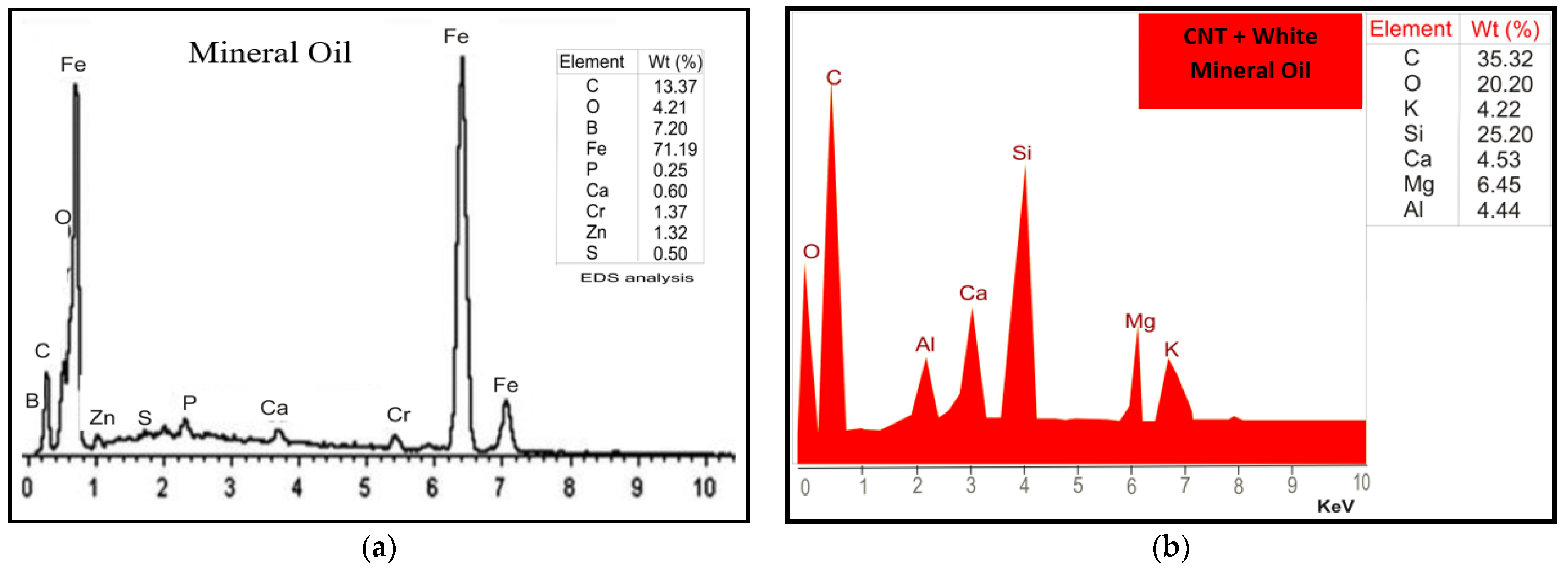
The nanofluid was prepared using multi-walled carbon nanotubes (MWCNT). The size of the nanoparticles ranges from 10 nm ± 1 nm to 4.5 ± 0.5 nm with 3–6 µm. The lubricant was prepared using white mineral oil, which is a vegetable-based oil, as the base fluid. The lubricant was prepared by dispersing the nanoparticles in the base fluid at a concentration of 0.4 g per liter of vegetable oil. This was achieved via an ultrasonication process that lasted about 3 h. The process helped to prevent particle agglomeration and generate a homogenous mixture. The SEM and EDX analyses of the microstructural characteristics and the chemical compositions of both lubricants are shown in Figure 1 and Figure 2.

2.2. Experimental Setup

The cutting speed had values of 870 rpm, 1400 rpm, and 1800 rpm, the depth of cut was varied between 1 mm, 2 mm, and 3 mm, and the feed rate had values of 2 mm/rev, 4 mm/rev, and 6 mm/rev. Each experiment used a constant cut length of 170 mm. A high-speed steel (HSS) tool was employed for cutting, while mineral oil and MWCNT lubricants were used as coolants. A Dinolite microscope and laptop were used to measure the tool wear. After each machining operation, the workpiece was placed under the lens of the microscope, and magnifications of 20× and 60× were then used to obtain proper high-resolution images of the worn cutting tool. The images were calibrated at different magnifications to give accurate measurements. Tool wear images were obtained separately for mineral oil machining and nanofluid machining; the experimental setup for the tool wear measurement and the machining process are given in Figure 3. In order to be sure that the machining process is accurately carried out, the study employed Taguchi techniques to define the variation of the machining parameters.

2.3. Finite Element Modelling

Finite element analysis is a widely used strategy for mathematically addressing differential conditions emerging in engineering and modeling. It is regularly featured in the analysis of phenomena such as heat transfer, electromagnetic behavior, fluid flow, and structural integrity. Such analyses can be carried out using partial differential boundaries and equations, but in complicated situations, which usually feature multiple distinct and extremely variable equations, the finite element method is used. It breaks a problem down into smaller units called finite elements. These elements are then addressed individually, and their solutions are congregated back into the large body of equations that model the entire problem. The finite element method works by generating a mesh consisting of millions of small elements that add up to the whole shape. This allows a full 3D object to be converted into mathematical points that can be evaluated. The mesh density can be tweaked depending on the complexity of the simulation needed. Evaluations are run for each element or node under certain boundary conditions, and then the results are combined into one mesh with the final result. This whole process is called “discretion”. Finite element analysis for tool wear requires some boundary conditions and models for a realistic simulation. These models include:
  • Friction Law: One of the common ways of characterizing tool-chip friction is by assuming Coulomb’s friction law, where the coefficient of friction is taken to be uniform over the entire rake surface. The coefficient of friction (µ) is the ratio of the cutting force parallel (frictional stress) to the tool rake face to the force normal (normal stress) to the rake face. The friction or contact force acting between the cutting tool and the workpiece was modeled according to Coulomb’s law, using Equation (1).
    τ = µ   k
    where µ = coefficient of friction, k = normal stress, τ = frictional stress.
Wear Rate Model: The analytical solution that is concerned with the wear rate was modeled using the tool wear rate model. The model estimates the tool wear behavior of high-speed steel-cutting tools by incorporating the effects of sliding velocities, interface temperatures, and contact pressures on the rate of tool wear. It is given by Equation (2):
Dw dt = A 1 σ n Vexp ( C T )
For regression analysis, the equation can be written as Equations (3) and (4): Where A1 and C are the model constants of tool materials, V is the sliding velocity in m/s, σn is the contact pressure in bars, T is the temperature in °C at the tool interface, and W is the tool wear rate in mm.
Dw / dt σ nV = A 1 exp ( C T )
σ jc = [ A + B ( ϵ ) n ] × [ 1 + Cln ( · · 0 ) ] × [ 1 ( T T 0 T m T 0 ) ]
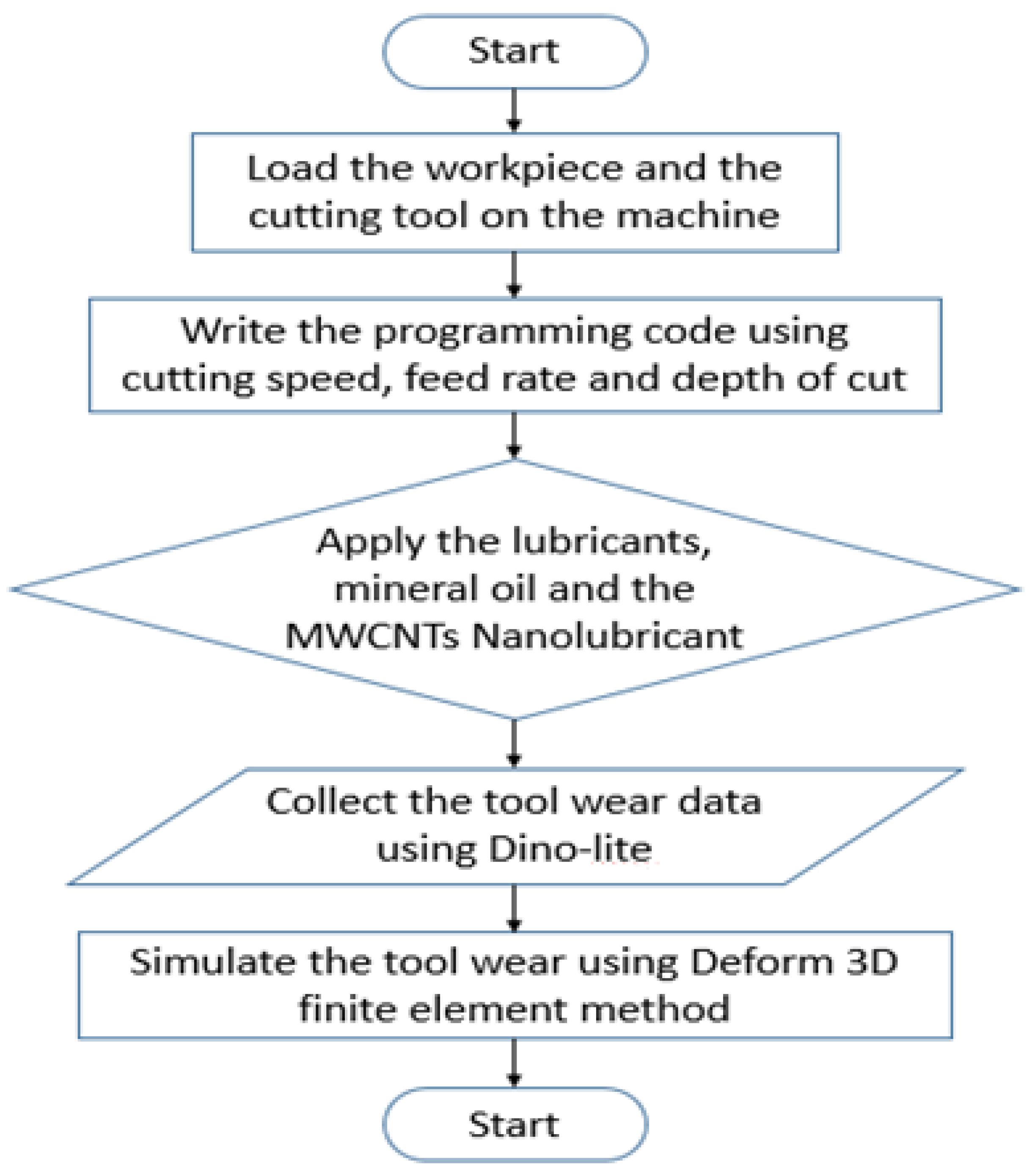
where, σ = stress movement, · 0 = soft strain rate reference, · = corresponding plastic strain rate, ϵ = corresponding soft strain, T = cutting temperature, Tm = melting temperature and T0 = ambient temperature (°C). The flow chart of the experimental procedure employed in this study is presented in Figure 4.
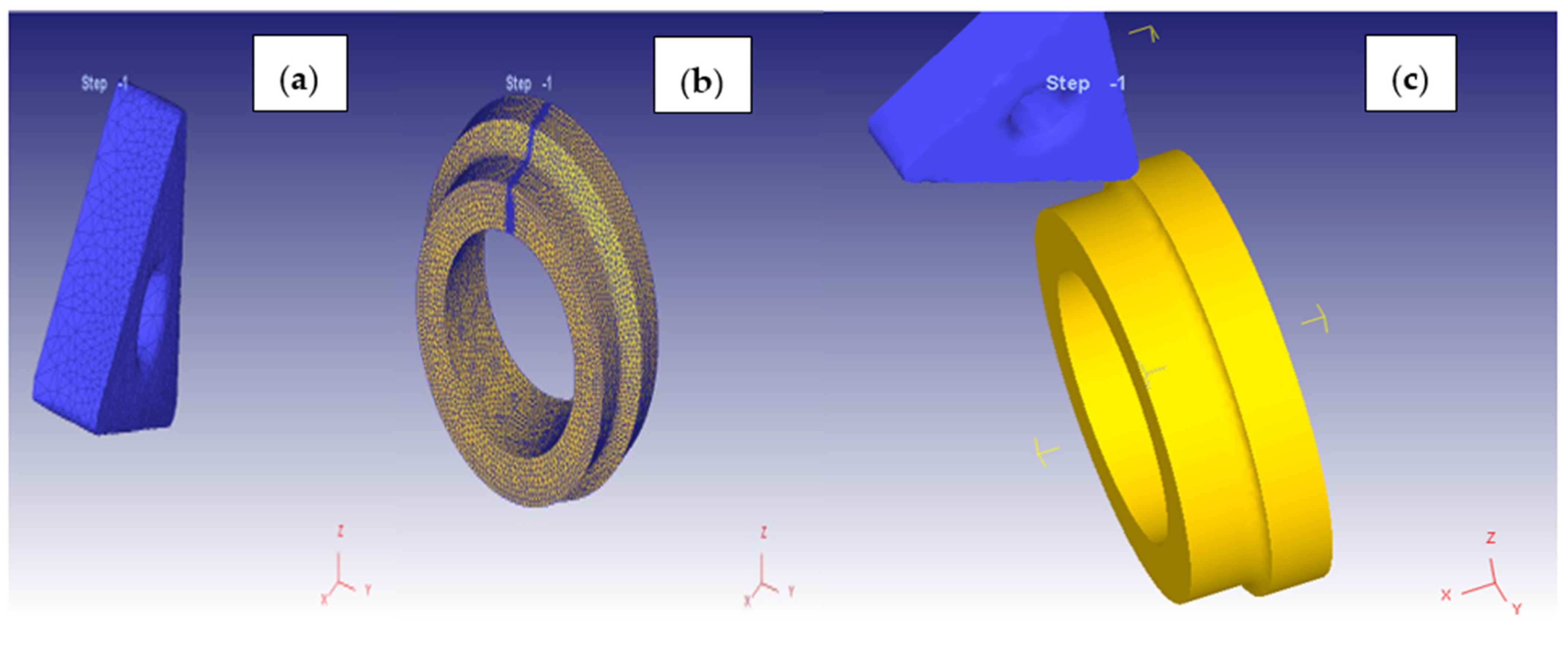
The 3D simulation was carried out on Deform 3D using a Euler-Lagrangian approach. The ambient temperature for the process was set at 27 °C with a convection coefficient of 0.02 N/s/mm/C. At the junction of the tool and workpiece, the shear friction factor was assigned a value of 0.6, while the heat transfer coefficient had a value of 45 N/s/mm/C. The tool mesh had a size ratio of 4, with a relative mesh size of 12,551, giving rise to a total of 3536 nodes in constant heat exchange with their surroundings. The workpiece was modeled as a plastic object at a temperature of 27 °C. It was a curved model with a diameter of 24 mm and an arc angle of 360. The mesh of the workpiece was created using an absolute mesh with 25,358 elements present and a size ratio of 7, as shown in Figure 5a–c. This generated a total of 19,322 nodes in constant thermal exchange with their immediate environment. The workpiece material was chosen as Al-Si-Mg alloys. The tool wear that was calculated with the Usui wear model had its calibrated coefficients set to 10−5 and 1000, respectively. The Johnson-Cook model was applied to simulate the deformation in correspondence with the workpiece material selected.

2.4. Taguchi Experimental Design

The Taguchi experimental design is a reliable statistical tool that delivers a final product with reduced variation. The goal of the Taguchi method is to facilitate a product that is robust enough for an unpredictable parameter. The experiments are designed and sequentially performed by following a matrix, which is known as the orthogonal array. Taguchi separates the experimental factors into controllable and random factors. The controllable factors form the interior array at different levels, while the noise factors form the exterior array, which is determined by the different levels of internal controllable or signal factors. Taguchi’s design can be used for both static and dynamic analysis.
Static analysis: This type of analysis is performed when there is no signal factor and encompasses the mean response. It makes use of only the control and noise factors for optimization.
Dynamic analysis: This type of analysis is performed when there is a signal factor and uses the control, noise, and signal factors for optimization. It encompasses a slope response from linear regression.
Control factors: These factors can be precisely controlled by the producer.
Noise factors: These are uncontrollable elements.
Signal Factors: These factors can be precisely determined by the operator, but not by the producer.
In addition to the orthogonal array that is used to design experiments, another key tool is the signal-to-noise ratio. The signal-to-noise ratio is usually evaluated and applied for optimization. Commonly seen as S/N ratios, signal-to-noise ratios are logarithmic functions of the required output in general, as shown in Equation (5)
S / N = Signal Noise = Mean Variation
The signal-to-noise ratio makes use of the Taguchi quality loss function to determine the difference between the required and experimental results. The signal-to-noise ratio tool is used in three ways: the smaller, the better, and the nominal, the best.
The smaller the better: in such a case, a smaller output is indicative of a better result. The analysis of tool wear sustained during machining falls under this category. Mathematically, the S/N ratio is shown in Equation (6):
S N = 10 log ( Σ ( Y 2 ) n )
The larger the better: in such a case, a larger output suggests a better result. Mathematically, the S/N ratio is Equation (7):
S N = 10 log ( Σ ( 1 Y 2 ) n )
The nominal is the best: mathematically, the S/N ratio is Equation (8):
S N = 10 log ( s 2 )
where n is the number of responses for a factor combination at a level, and Y is the number of responses for a factor combination at a level. The study adopts the smaller the better principle.
The experimental design for the machining experiments was based on a Taguchi L9 orthogonal array. Three factors—spindle speed, feed rate, and depth of cut—formed the interior array, while the output response targeted was the tool wear obtained at the end of machining. Each factor had three different levels. The Taguchi design for the experiment is shown in Table 3.

3. Results and Discussion

A series of experiments were carried out as designed by the Taguchi L9 orthogonal array. Each experimental run was carried out using mineral oil as well as multi- walled carbon-nanotubes lubricant. Tool wear values and machining duration were measured and recorded in each case. The results gotten from the experiments are shown in Table 4.

3.1. Effect of Depth of Cut, Feed Rate, and Cutting Speed on Tool Wear

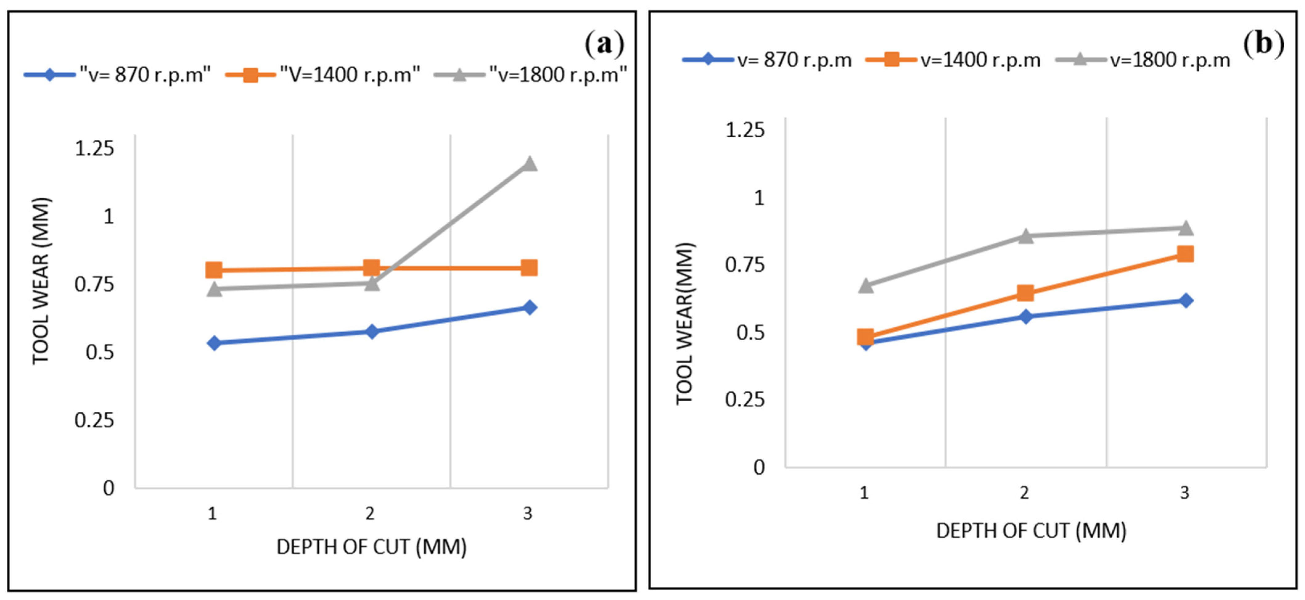
Three values (1 mm, 2 mm, and 3 mm) were selected as parameters for the depth of cut. Figure 6a,b depicts the variation of tool wear with depth of cut at three different cutting speeds (870 rpm, 1400 rpm, and 1800 rpm) and lubrication environments of mineral oil and MWCNT. An analysis of the results shows that, on average, an increase in the depth of cut leads to an increase in tool wear and hence a reduction in tool life. Results show that the highest tool wear values of 1.193 mm and 0.888 mm were produced under the highest depth of cut of 3 mm for mineral oil and MWCNT environments, respectively. Şap et al. [22] carried out a study on the machining process of Cu/Mo/SiCp composite. The study employed the three machining factors of spindle speed, depth of cut, and feed rate, while studying tool wear as one of the response parameters. The results show that the depth of cut increases the tool wear rate when increased during the cutting process. Also, the increase in the depth of cut increased the chip formulation. One significant reason for studying composite materials during the cutting process is that they possess high strength and hardness, but they have a low thermal expansion after the machining of composite materials during the production process. The study carried out by Usca et al. [23] also supported the concept of the findings.
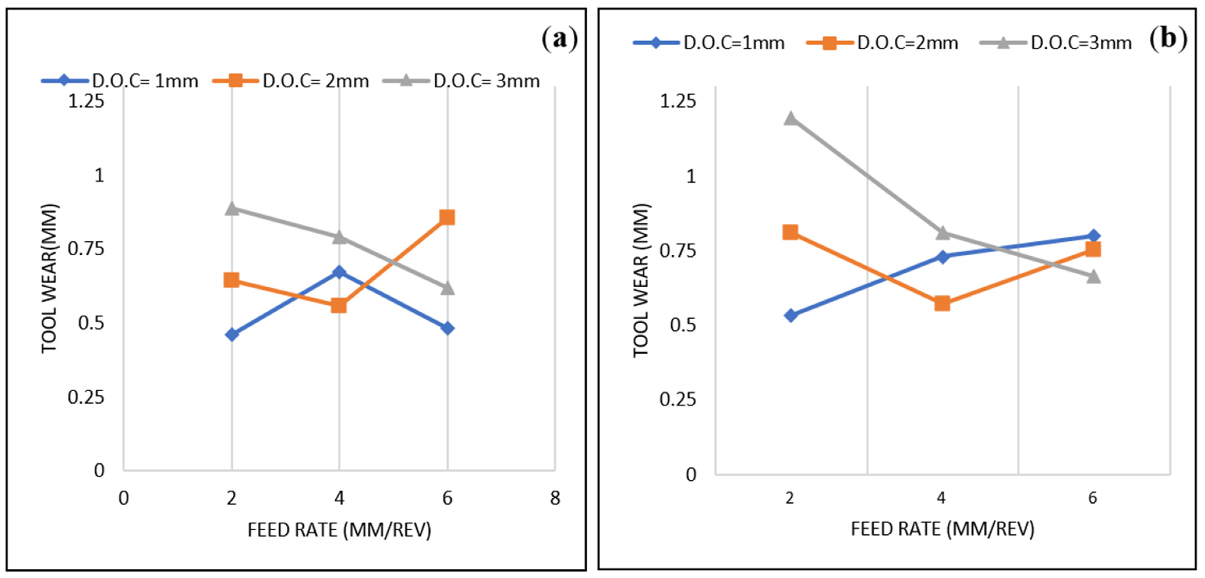
An analysis of the results shows that for lower cutting speeds, an increase in feed rate leads to an increase in tool wear. However, for greater cutting speeds, the influence of feed rate on tool wear decreases. Figure 7a,b shows the relationship between tool wear and feed rate at various cut depths. This result is in line with the findings of Okokpujie et al. [24] and Yılmaz et al. [25].
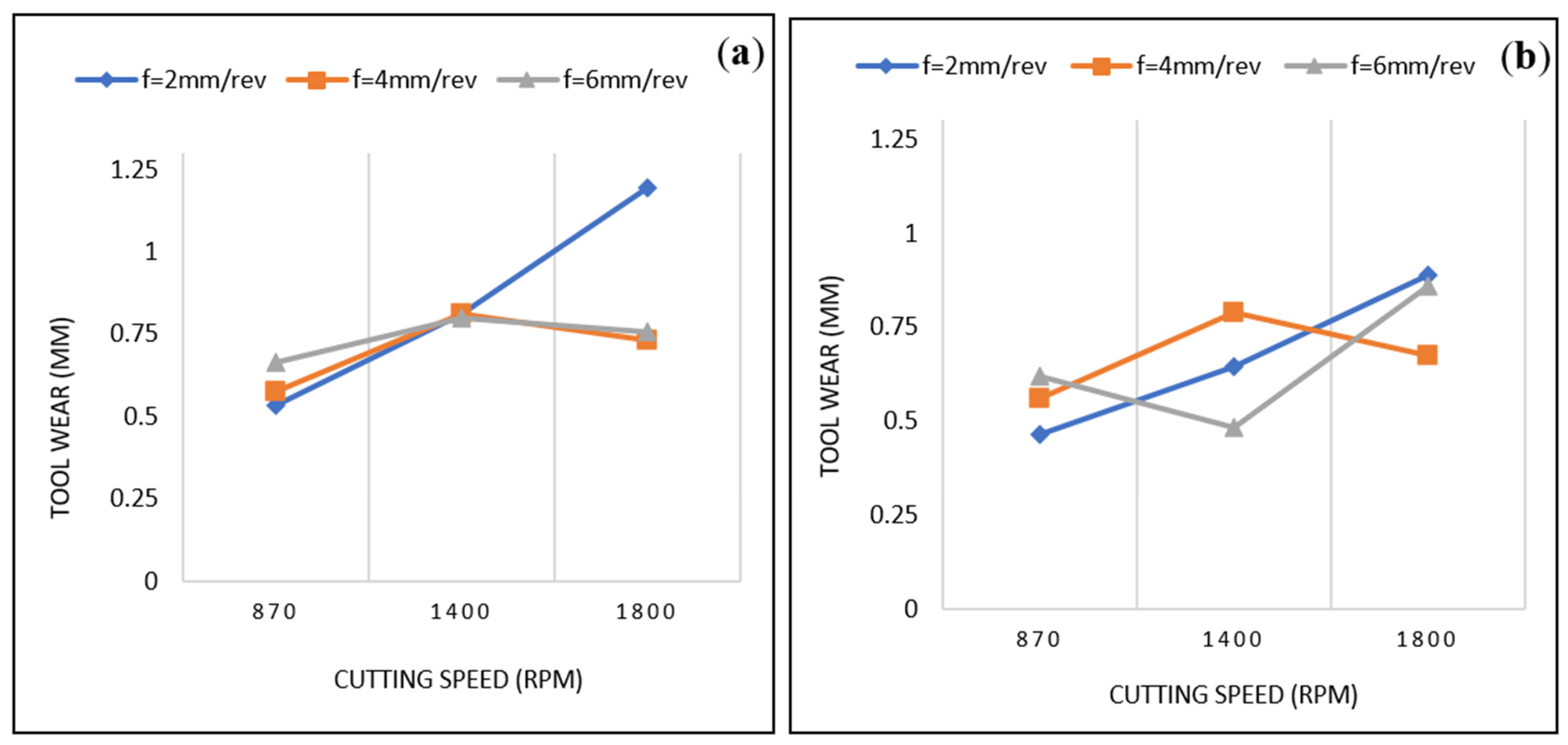
In line with the observations of Gunan et al. [13], there was an increase in tool wear and a reduction in tool life whenever cutting speed increased. Maximum wear was observed at cutting speeds of 1800 rpm for both mineral oil and MWCNT. However, a combination of high cutting speed and low depth of cut produces tool wear results in the medium range. The Figure 8a,b depicts the relationship between cutting speed and tool wear at various feed rates.

3.2. Effect of Lubricants on Machining Time

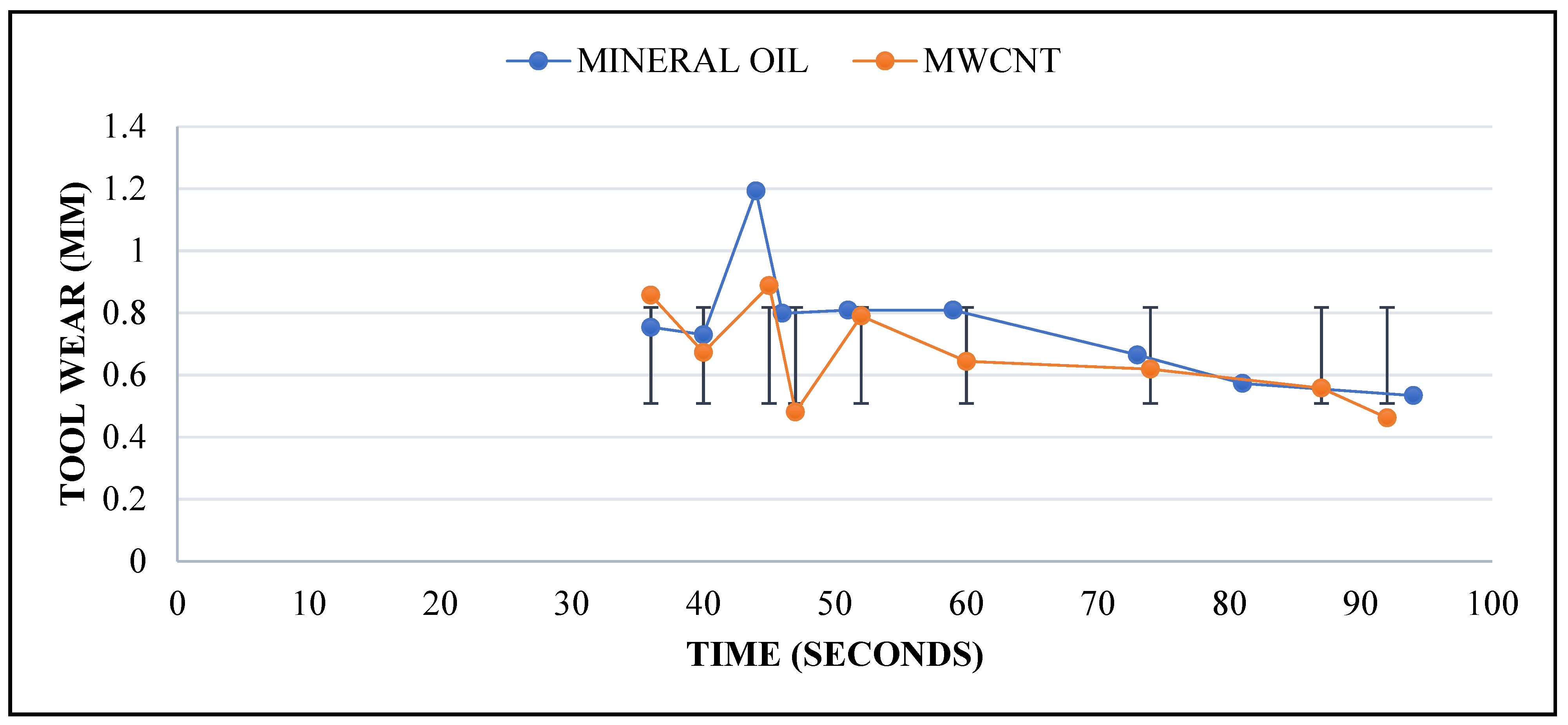
The time taken for each run was observed under the influence of mineral oil and MWCNT lubricants. It was observed that, for the same length, machining with the lubricant took more time than machining with pure mineral oil. This could be attributed to the tubular and layered chemical structure of the MWCNT particles, which gives a physical appearance that is thicker and more viscous than that of the mineral oil. Figure 9 shows the relationship between tool wear and machining time as influenced by the lubricants.

3.3. Tool Wear Comparison under the Lubricants

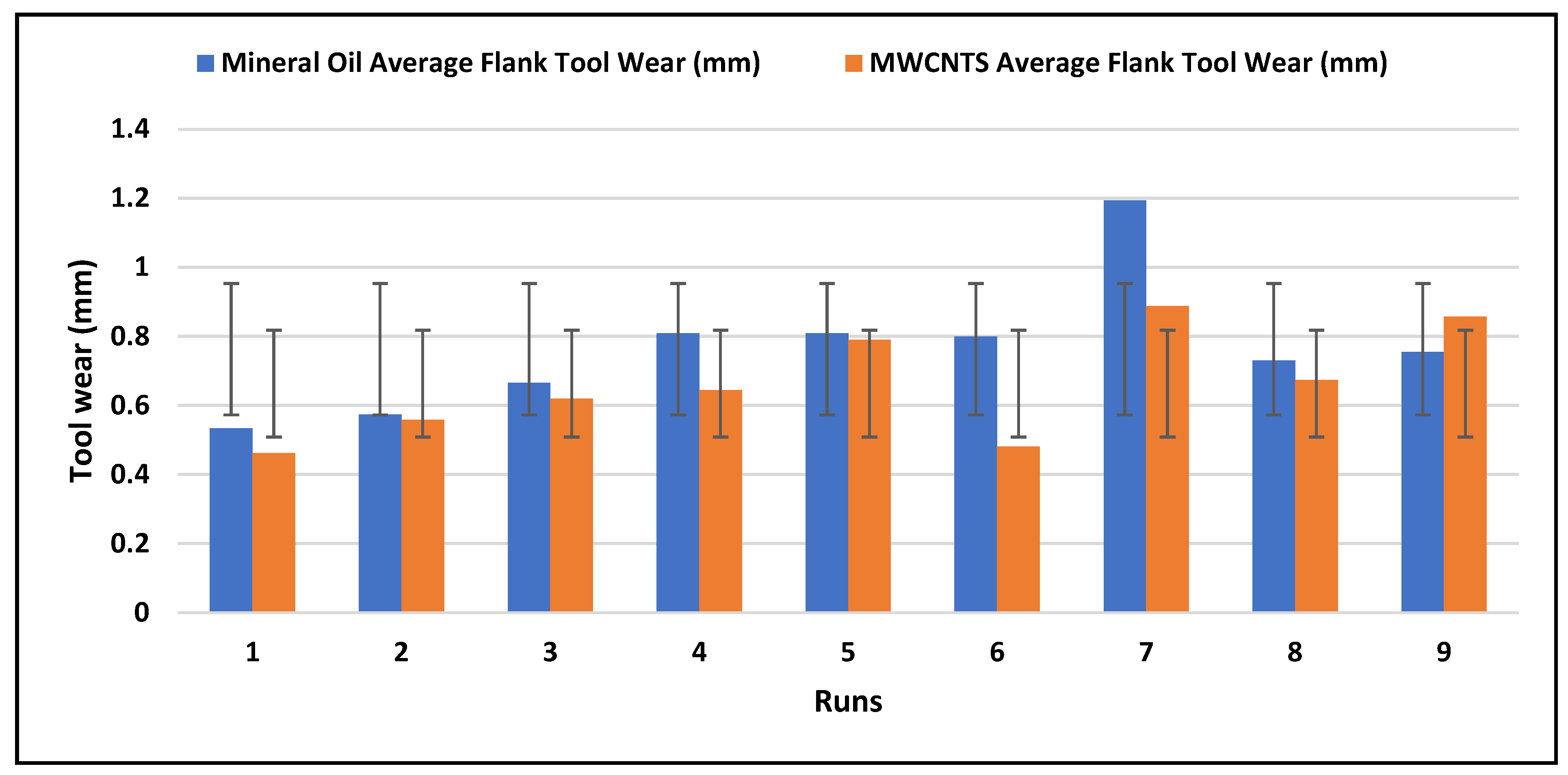
Lubrication had a significant influence on tool wear. The tool wear was observed under mineral oil and MWCNT lubricants. The MWCNT lubricant proved to be significantly better at reducing tool wear than mineral oil. When machining with CNT particles, tool wear was reduced by 13.4%, 2.6%, 6.9%, 20.39%, 2.3%, 39.8%, 25.6%, and 7.8% when compared to mineral oil machining. Figure 10 shows a comparison of tool wear under the two lubricants. Figure 11, Figure 12 and Figure 13 show tool wear images captured by the Dino-lite microscope. From the experimental observation, the application of the MWCNT nanoparticles in the mineral oil increases the cooling rate of the lubricant during the turning operations due to the increase in the oxygen percentage in the cutting fluid, and it also increases the slippery tendency of the nano-lubricant that helps to reduce friction. According to several studies, friction is one of the major causes of vibration, which in turn leads to the breakage of cutting tool tips. The application of the MWCNT nanoparticles in the mineral oil is to prolong the life of the cutting tool, which, when prolonged, helps to reduce surface finishing during operations.
Figure 11a,b shows images of tool wear generated under (A) mineral oil and (B) MWCNTs. Nano-lubricant at cutting speeds of 870 rpm, a feed rate of 2 mm, and a depth of cut of 1 mm produce the highest tool wear rate, with a length of wear measurement (L) of 10.216 mm and an area of measurement (A) of 3.162 mm2. with a length of wear measurement (L) of 7.149 mm and an area of measurement (A) of 1.692 mm2 for mineral oil. This is due to the deformation process that occurred as a result of the time effects on the cutting tool life. However, from observation, it was seen that mineral oil has a faster machining time, but the lowest cooling rate during the machining procedures. Therefore, the effects of the temperature at the cutting zone lead to a high rate of the cutting tool wearing out at the same machining length of 170 mm for the Al-Si-Mg alloy materials [26]. The MWCNTs nano-lubricant machining environments reduce the tool wear due to the nanoparticles on the mineral oil, which increase the cooling rate, and also deposit a thin film on the surface of the cutting tool and workpieces, which assists in converting the sliding friction into rolling friction, which helps to reduce the vibration occurrences at the cutting regions [27].
Figure 12a,b shows the images of tool wear generated under (A) mineral oil and (B) MWCNTs nano-lubricant at cutting speeds of 1400 rpm, a feed rate of 2 mm, and a depth of cut of 1 mm. From the study, as the spindle speed increases, the tool wear reduces; this can be seen from the results obtained from the microstructure analysis of the Dino-lite in Figure 12a,b: length of wear measure (L) = 7.040 mm, area of measurement (A) = 2.097 mm2 for mineral oil, and MWCNTs cutting fluid with the length of wear measure (L) = 6.653 mm, area of measurement (A) = 1.619 mm2.
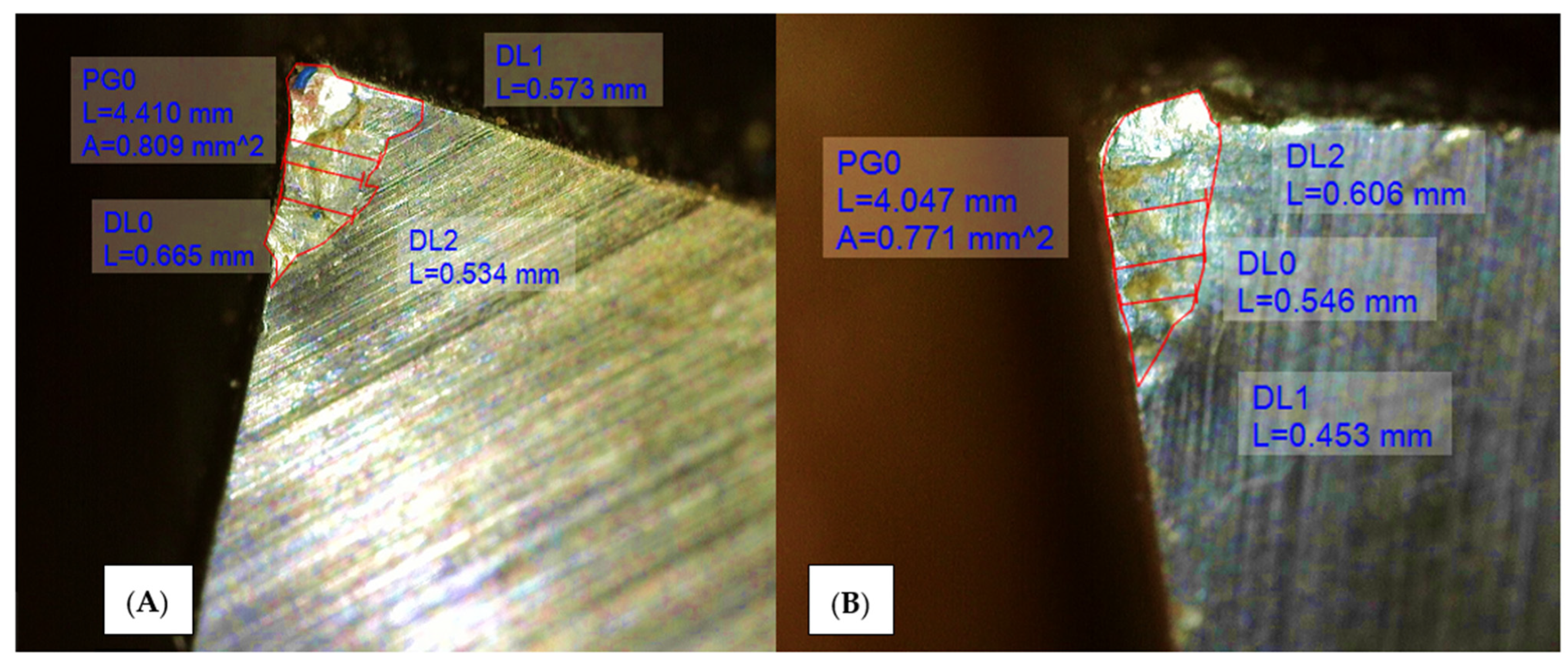
Figure 13a,b presents the images of tool wear generated under (A) mineral oil and (B) MWCNTs nano-lubricant at cutting speeds of 1800 rpm, a feed rate of 2 mm, and a depth of cut of 1 mm. This increase in the spindle speed in all three categories of the machining process shows that tool wear decreases. From Figure 13a,b, the microstructure measurements are given as the length of wear measure (L) = 4.410 mm, area of measurement (A) = 0.809 mm2 for mineral oil, and for MWCNTs cutting fluid, the length of wear measure (L) = 4.047 mm, area of measurement (A) = 0.771 mm2.

3.4. Chip Morphology

It was observed that discontinuous chips were formed at lower spindle speeds (870 rpm) due to vibration and friction during the turning process.
Also, continuous chips with the highest spindle speed (1800 rpm) were achieved due to the increase in the cutting speed that helped eliminate the build-up at the turning region. The average chip thickness was measured at 0.13 mm, while the average width was measured at 0.709 mm. The various types of chips produced during the machining process are depicted in Figure 14a,b.

3.5. Comparative Analysis of the Various Spindle Speed of 870 rpm, 1400 rpm, and 1800 rpm via Simulation Approach

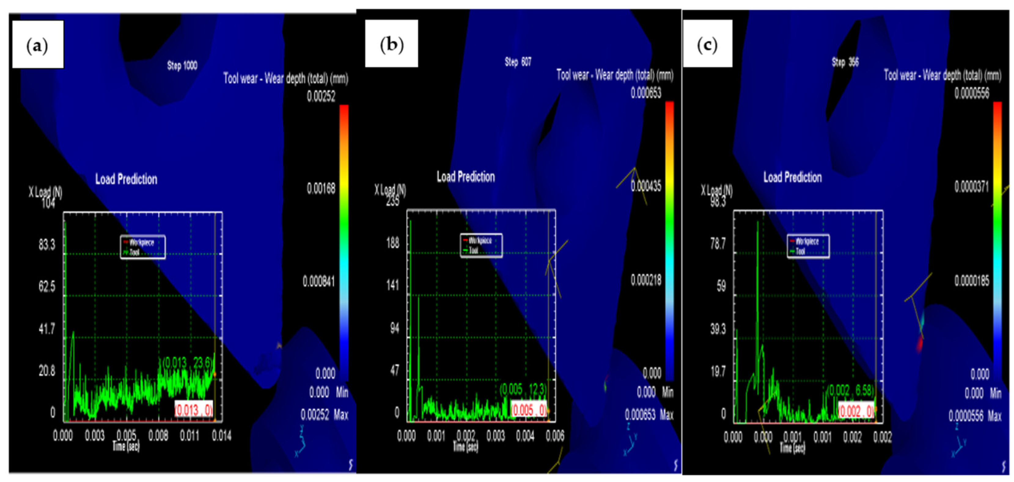
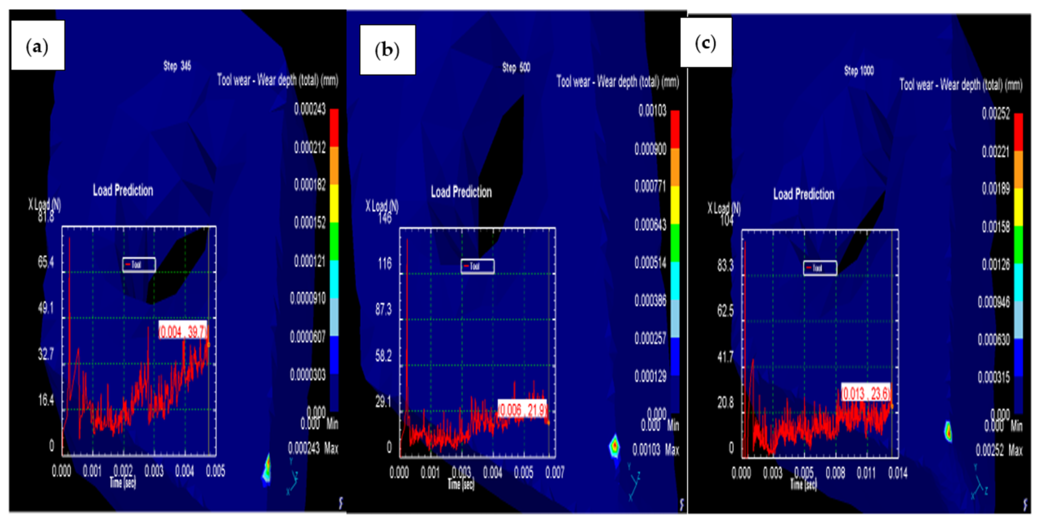
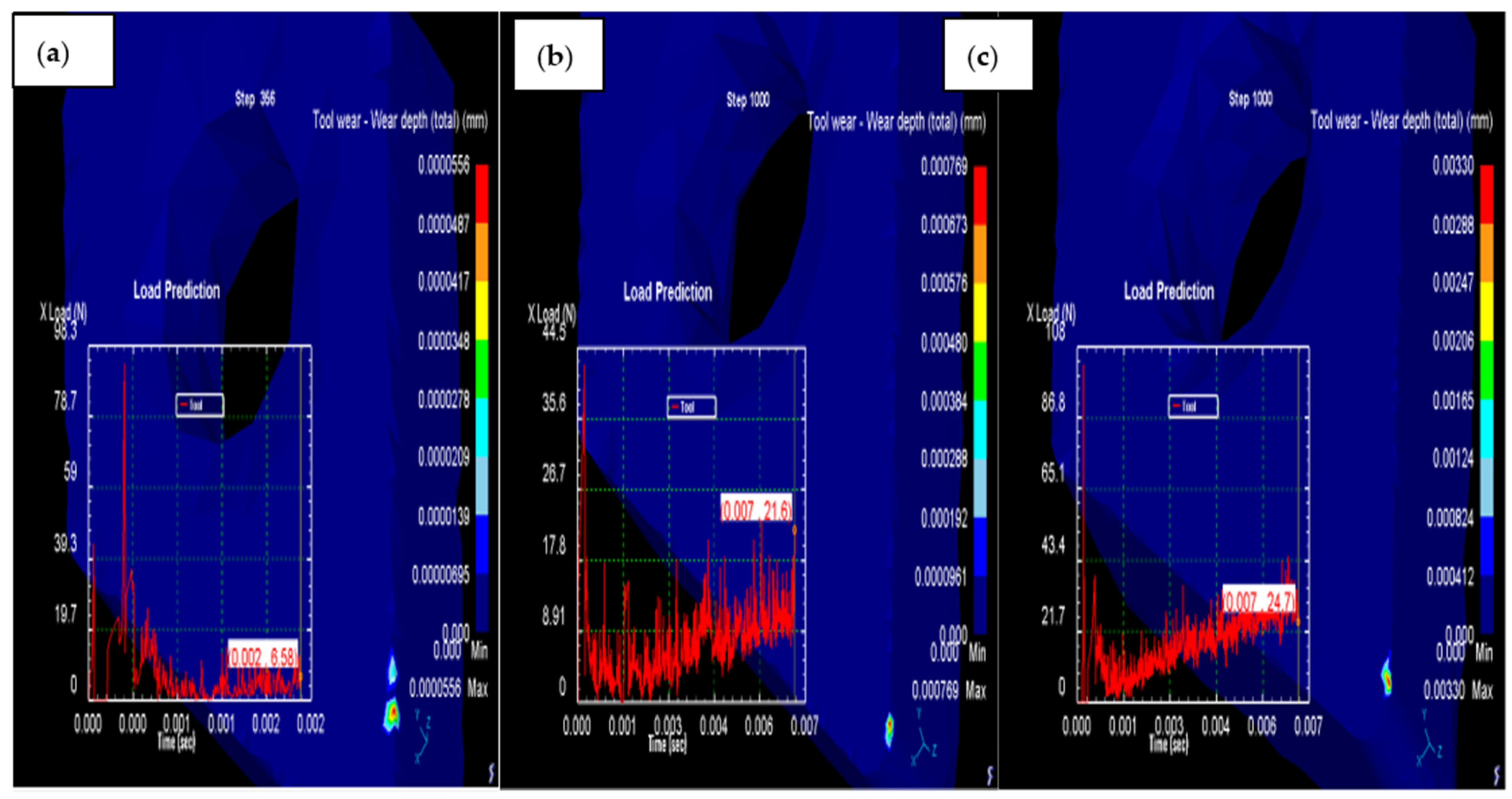
Figure 15, Figure 16, Figure 17 and Figure 18 show the results of the simulations (Usui’s wear model) for three selected runs; the color coding on the images shows the intensity of the wear at different levels. Figure 15a,b shows the simulation of a maximum wear depth of 2.5 × 10⁻³ mm accompanied by a load of 100 N before a series of crests and troughs representing a relatively uniform load distribution. Figure 16a,b gives the simulation analysis of a maximum wear depth of 6.5 × 10⁻⁴ mm accompanied by a load of 225 N. Figure 17a,b illustrates the simulation of a maximum wear depth of 0.5 × 10⁻⁴ mm accompanied by a load of 100 N. The tool wear area was the largest, with most of its load intensities evenly spread. However, it can be seen in this simulation that the effect of the depth of cut is paramount in this study.
From the load prediction with time analysis, it can be observed that the cutting parameter produces vibration as the cutting tool come in contact with the workpiece, as shown in Figure 15a–c. The vibration is higher at the lower cutting speed, while as the speed increases the vibration reduces. In contrast, the feed rate increases the vibration as it increases, and this is also observed with the increase of the depth of cut. It was also observed in the experimental result obtained from the turning operations.
When comparing the effects of the different feed rates and the depth of cut in Figure 18a–c, Figure 18a has a high wear rate of the cutting tool due to the 3 mm depth of cut. The wear rate of the cutting tool decreases as the depth of cut decreases (see Figure 18b), where the depth of cut is 1 mm. However, Figure 18c shows that both the feed rate and the depth of cut increase tool wear via the simulation process. This result is in line with the result obtained from the experiment and the study of [28].

4. Conclusions

This research was carried out to study the effects of the turning environment, such as mineral oil and MWCNTs nano-turning processes, and the effects of the cutting parameters, with the time of turning on the high-speed steel cutting tool wear rate with chip formulations. Also, the research implemented deformed 3D simulation techniques to simulate the tool wear rate at various turning parameters. The experimental investigations give rise to the following conclusions:
  • The multi-walled carbon nanotube (MWCNT) lubricant is more effective at reducing tool wear than the mineral oil lubricant, with an average reduction rate of 14.8%.
  • The tool wear was greatly influenced by the process parameters, with the depth of cut being the most significant parameter. This observation is obtained from both the experimental and the finite-element 3D simulation.
  • The influence of feed rate on tool wear decreases as cutting speed increases.
  • For the same process parameters and machining conditions, MWCNT lubrication increased the machining time. This is due to the thick and viscous nature of the MWCNT as compared to the mineral oil.
  • Higher cutting speeds produced continuous chips, while lower and medium cutting speeds produced discontinuous chips.
  • It can also be confirmed by the deformed 3D simulation software that the turning parameters have significant effects on the turning process, such as the depth of cut and the feed rate. From the deform 3D analysis, it can also be seen that the vibration analysis is high with a cutting speed of 870 rpm when compared with the 1400 rpm cutting speed.

Author Contributions

Conceptualization, I.P.O., P.C.C. and L.K.T. and I.P.O., P.C.C. and L.K.T.; methodology, I.P.O., P.C.C. and L.K.T.; software, I.P.O., P.C.C. and L.K.T.; validation, I.P.O., P.C.C., L.K.T., I.P.O., P.C.C., L.K.T., I.P.O., P.C.C. and L.K.T.; formal analysis, I.P.O., P.C.C. and L.K.T.; investigation, I.P.O., P.C.C. and L.K.T.; resources, I.P.O., P.C.C. and L.K.T.; data curation, I.P.O., P.C.C. and L.K.T.; writing—original draft preparation, I.P.O., P.C.C. and L.K.T.; writing—review and editing, L.K.T.; visualization, I.P.O.; supervision, I.P.O.; project administration, I.P.O.; funding acquisition, L.K.T. All authors have read and agreed to the published version of the manuscript.

Funding

This research received no external funding.

Data Availability Statement

All the data available in this work.

Conflicts of Interest

The authors declared no conflict of interest.

References

  1. Okokpujie, I.P.; Ikumapayi, O.; Okonkwo, U.C.; Salawu, E.Y.; Afolalu, S.A.; Dirisu, J.; Nwoke, O.N.; Ajayi, O. Experimental and Mathematical Modeling for Prediction of Tool Wear on the Machining of Aluminium 6061 Alloy by High Speed Steel Tools. Open Eng. 2017, 7, 461–469. [Google Scholar] [CrossRef]
  2. Aslantas, K.; Danish, M.; Hasçelik, A.; Mia, M.; Gupta, M.; Ginta, T.; Ijaz, H. Investigations on Surface Roughness and Tool Wear Characteristics in Micro-Turning of Ti-6Al-4V Alloy. Materials 2020, 13, 2998. [Google Scholar] [CrossRef] [PubMed]
  3. Anand, R.; Raina, A.; Haq, M.I.U.; Mir, M.J.; Gulzar, O.; Wani, M.F. Synergism of TiO2 and Graphene as Nano-Additives in Bio-Based Cutting Fluid—An Experimental Investigation. Tribol. Trans. 2021, 64, 350–366. [Google Scholar] [CrossRef]
  4. Aslan, A. Optimization and analysis of process parameters for flank wear, cutting forces and vibration in turning of AISI 5140: A comprehensive study. Measurement 2020, 163, 107959. [Google Scholar] [CrossRef]
  5. Sarıkaya, M.; Şirin, S.; Yıldırım, V.; Kıvak, T.; Gupta, M.K. Performance evaluation of whisker-reinforced ceramic tools under nano-sized solid lubricants assisted MQL turning of Co-based Haynes 25 superalloy. Ceram. Int. 2021, 47, 15542–15560. [Google Scholar] [CrossRef]
  6. Rapeti, P.; Pasam, V.K.; Gurram, K.M.R.; Revuru, R.S. Performance evaluation of vegetable oil based nano cutting fluids in machining using grey relational analysis-A step towards sustainable manufacturing. J. Clean. Prod. 2018, 172, 2862–2875. [Google Scholar] [CrossRef]
  7. Jamil, M.; He, N.; Li, L.; Khan, A.M. Clean manufacturing of Ti-6Al-4V under CO2-snow and hybrid nanofluids. Procedia Manuf. 2020, 48, 131–140. [Google Scholar] [CrossRef]
  8. Venkatesan, K.; Mathew, A.T.; Devendiran, S.; Ghazaly, N.M.; Sanjith, S.; Raghul, R. Machinability study and multi-response optimization of cutting force, Surface roughness and tool wear on CNC turned Inconel 617 superalloy using Al2O3 Nanofluids in Coconut oil. Procedia Manuf. 2019, 30, 396–403. [Google Scholar] [CrossRef]
  9. Sharma, A.K.; Tiwari, A.K.; Dixit, A.R.; Singh, R.K.; Singh, M. Novel uses of alumina/graphene hybrid nanoparticle additives for improved tribological properties of lubricant in turning operation. Tribol. Int. 2018, 119, 99–111. [Google Scholar] [CrossRef]
  10. Kursuncu, B.; Yaras, A. Assessment of the effect of borax and boric acid additives in cutting fluids on milling of AISI O2 using MQL system. Int. J. Adv. Manuf. Technol. 2017, 95, 2005–2013. [Google Scholar] [CrossRef]
  11. Zhou, C.; Guo, X.; Zhang, K.; Cheng, L.; Wu, Y. The coupling effect of micro-groove textures and nanofluids on cutting performance of uncoated cemented carbide tools in milling Ti-6Al-4V. J. Mater. Process. Technol. 2019, 271, 36–45. [Google Scholar] [CrossRef]
  12. Peña-Parás, L.; Rodríguez-Villalobos, M.; Maldonado-Cortés, D.; Guajardo, M.; Rico-Medina, C.S.; Elizondo, G.; Quintanilla, D.I. Study of hybrid nanofluids of TiO2 and montmorillonite clay nanoparticles for milling of AISI 4340 steel. Wear 2021, 477, 203805. [Google Scholar] [CrossRef]
  13. Günan, F.; Kıvak, T.; Yıldırım, V.; Sarıkaya, M. Performance evaluation of MQL with AL2O3 mixed nanofluids prepared at different concentrations in milling of Hastelloy C276 alloy. J. Mater. Res. Technol. 2020, 9, 10386–10400. [Google Scholar] [CrossRef]
  14. Hegab, H.; Darras, B.; Kishawy, H. Sustainability Assessment of Machining with Nano-Cutting Fluids. Procedia Manuf. 2018, 26, 245–254. [Google Scholar] [CrossRef]
  15. Barewar, S.D.; Kotwani, A.; Chougule, S.S.; Unune, D.R. Investigating a novel Ag/ZnO based hybrid nanofluid for sustainable machining of inconel 718 under nanofluid based minimum quantity lubrication. J. Manuf. Process. 2021, 66, 313–324. [Google Scholar] [CrossRef]
  16. Shi, Z.; Li, X.; Duan, N.; Yang, Q. Evaluation of tool wear and cutting performance considering effects of dynamic nodes movement based on FEM simulation. Chin. J. Aeronaut. 2020, 34, 140–152. [Google Scholar] [CrossRef]
  17. Koopaie, M.; Kolahdouz, S.; Kolahdouz, E. Comparison of wear and temperature of zirconia and tungsten carbide tools in drilling bone: In vitro and finite element analysis. Br. J. Oral Maxillofac. Surg. 2019, 57, 557–565. [Google Scholar] [CrossRef] [PubMed]
  18. Gao, Y.; Ko, J.H.; Lee, H.P. Meso-scale tool breakage prediction based on finite element stress analysis for shoulder milling of hardened steel. J. Manuf. Process. 2020, 55, 31–40. [Google Scholar] [CrossRef]
  19. Yıldız, A.; Kurt, A.; Yağmur, S. Finite element simulation of drilling operation and theoretical analysis of drill stresses with the deform-3D. Simul. Model. Pr. Theory 2020, 104, 102153. [Google Scholar] [CrossRef]
  20. Paturi, U.M.R.; Methuku, S.; Siripragada, S.S.; Sangishetty, Y.; Gunda, R.K. Finite element simulations of machinability parameters in turning of Inconel 718. Mater. Today: Proc. 2020, 38, 2658–2663. [Google Scholar] [CrossRef]
  21. Watmon, T.B.; Xiao, D.; Peter, O.O. Finite element analysis of orthogonal metal machining. Int. J. Sci. Res. Inn. Tech. 2016, 3, 46–55. Available online: http://hdl.handle.net/20.500.12283/818 (accessed on 25 October 2022).
  22. Şap, E.; Usca, U.A.; Gupta, M.K.; Kuntoğlu, M. Tool wear and machinability investigations in dry turning of Cu/Mo-SiCp hybrid composites. Int. J. Adv. Manuf. Technol. 2021, 114, 379–396. [Google Scholar] [CrossRef]
  23. Usca, A.; Uzun, M.; Kuntoğlu, M.; Sap, E.; Gupta, M.K. Investigations on tool wear, surface roughness, cutting temperature, and chip formation in machining of Cu-B-CrC composites. Int. J. Adv. Manuf. Technol. 2021, 116, 3011–3025. [Google Scholar] [CrossRef]
  24. Okokpujie, I.P.; Bolu, C.A.; Ohunakin, O.S.; Akinlabi, E.T. Experimental Study of the Effect of TiN–Zn Coated High-Speed Steel Cutting Tool on Surface Morphology of AL1060 Alloy During Machining Operation. In Trends in Manufacturing and Engineering Management; Springer: Singapore, 2020; pp. 637–647. [Google Scholar] [CrossRef]
  25. Yılmaz, B.; Karabulut, Ş.; Güllü, A. A review of the chip breaking methods for continuous chips in turning. J. Manuf. Process. 2019, 49, 50–69. [Google Scholar] [CrossRef]
  26. Okokpujie, I.; Ohunakin, O.; Bolu, C.; Okokpujie, K. Experimental data-set for prediction of tool wear during turning of Al-1061 alloy by high speed steel cutting tools. Data Brief 2018, 18, 1196–1203. [Google Scholar] [CrossRef]
  27. Okokpujie, I.P.; Tartibu, L.K. Experimental analysis of cutting force during machining difficult to cut materials under dry, mineral oil, and TiO2 nano-lubricant. J. Meas. Eng. 2021, 9, 218–230. [Google Scholar] [CrossRef]
  28. Siddaligaprasad, T.; Shivashankar, H.; Chandrashekharaiah, T.; Ganiger, B. Optimization of machining conditions with D type cutting tools using Taguchi technique. Mater. Today Proc. 2021, 52, 2087–2094. [Google Scholar] [CrossRef]
Figure 1. SEM images of (a) White mineral oil and (b) a mixture of MWCNTs and white mineral oil.
Lubricants 10 00341 g001
Figure 2. EDX analysis on the (a) white mineral oil and (b) combination of multi-walled carbon nanotube and white mineral oil.
Lubricants 10 00341 g002
Figure 3. Experimental setup of the machining process and the tool wear measurement.
Lubricants 10 00341 g003
Figure 4. The flow chart of the method of the machining process and the implementation of the deformed 3D.
Lubricants 10 00341 g004
Figure 5. (a) Tool (b) the workpiece, and (c) workpiece mesh with the cutting tool.
Lubricants 10 00341 g005
Figure 6. The study of depth of cut and cutting speed on tool wear under (a) mineral oil lubricant (b) MWCNTs lubricant.
Lubricants 10 00341 g006
Figure 7. The study of feed rate and depth of cut on tool wear under (a) mineral oil (b) MWCNTs lubricant.
Lubricants 10 00341 g007
Figure 8. The study of cutting speed and feed rate on tool wear under (a) mineral oil (b) MWCNTs lubricant.
Lubricants 10 00341 g008
Figure 9. Plot of tool wear against machining time.
Lubricants 10 00341 g009
Figure 10. Tool wear comparison under mineral oil and MWCNTs lubricant.
Lubricants 10 00341 g010
Figure 11. Images of tool wear generated under (A) mineral oil and (B) MWCNTs nano-lubricant at cutting speeds of 870 rpm, feed rate 2 mm, and depth of cut 1 mm.
Lubricants 10 00341 g011
Figure 12. Images of tool wear generated under (A) mineral oil and (B) MWCNTs nano lubricant at cutting speeds of 1400 rpm, feed rate 2 mm, and depth of cut 2 mm.
Lubricants 10 00341 g012
Figure 13. Images of tool wear generated under (A) mineral oil and (B) MWCNTs nano-lubricant at cutting speeds of 1800 rpm, feed rate 2 mm, and depth of cut 3 mm.
Lubricants 10 00341 g013
Figure 14. (a) continuous chips produced under high-speed machining of 1800 rpm (b) discontinuous chips produced under low-speed machining of 870 rpm.
Lubricants 10 00341 g014
Figure 15. Tool wear 3D simulation analysis at (a) cutting speeds of 870 rpm, (b) 1400 rpm, and (c) 1800 rpm.
Lubricants 10 00341 g015
Figure 16. Tool wear analysis at cutting speeds of 870 rpm, at (a) feed rate 2 mm, depth of cut 1 mm (b) feed rate 4 mm, depth of cut 2 mm, and (c) feed rate 6 mm, depth of cut 3 mm.
Lubricants 10 00341 g016
Figure 17. Tool wear simulation analysis at cutting speeds of 1400 rpm, (a) feed rate 2 mm, depth of cut 2 mm (b) feed rate 4 mm, depth of cut 3 mm, and (c) feed rate 6 mm, depth of cut 1 mm.
Lubricants 10 00341 g017
Figure 18. Tool wear simulation analysis at cutting speeds of 1800 rpm, (a) feed rate 2 mm, depth of cut 3 mm (b) feed rate 4 mm, depth of cut 1 mm, and (c) feed rate 6 mm, depth of cut 2 mm.
Lubricants 10 00341 g018
Table 1. Equipment employed for the study.
Item Specifications
Lathe machineWARCO GH–1640ZX gear head precision Spindle speed range: 85–1800 (rpm)
Lathe Chuck Jaws (4-Jaw Chuck)
(1)
Used jaws
Cutting Tool InsertHigh-speed steel (HSS)
Chemical composition18% tungsten, 4% chromium, 1% vanadium, and only 0.5–0.8% carbon the balance is iron
Dino-lite digital microscopeAM3111 0.3MP Digital USB Microscope 10–50 X~230 X
Table 2. Composition of the Al-Si-Mg alloy material.
MaterialsFeSiMnCuZnMgPbSnAl
Percentage (%)1.272.4480.1080.4340.4921.20.1120.07393.87
Table 3. Experimental Template for the Tool Wear Analysis using L9 Taguchi Design.
Spindle Speed (rpm)Feed Rate (mm/rev)Depth of Cut (mm)Passes for the Simulation
870211st Pass
87042
87063
1400222th Pass
140043
140061
1800233rd Pass
180041
180062
Table 4. Experimental Results of the Tool Wear Obtained from the turning of Al-Si-Mg Alloy.
Cutting Speed
(rpm)
Feed Rate
(mm/rev)
Depth of Cut
(mm)
Mineral Oil Average
Flank Tool Wear (mm)
MWCNTS Average
Flank Tool Wear (mm)
Mineral Oil Machining Time
(s)
MWCNTS Machining Time (min/s)
870210.5340.4629492
870420.5730.5588187
870630.6650.6197374
1400220.8090.6445960
1400430.8090.795152
1400610.7990.4814647
1800231.1930.8884445
1800410.730.6734040
1800620.7540.8573636
Publisher’s Note: MDPI stays neutral with regard to jurisdictional claims in published maps and institutional affiliations.