1. Introduction
In the recent period, in connection with increasing the carrying capacity and reducing the noise level of automobile transmissions, further developments in the field of gears have also been implemented. The originally used standard involute gear, LCR (Low Contact Ratio), has been often replaced by non-standard involute gear with an extended contact ratio, which is called HCR (High Contact Ratio) [
1]. The LCR gear is characterized by the contact ratio below 2, as there are less than two teeth meshing at the same time. The HCR gear wheel, in
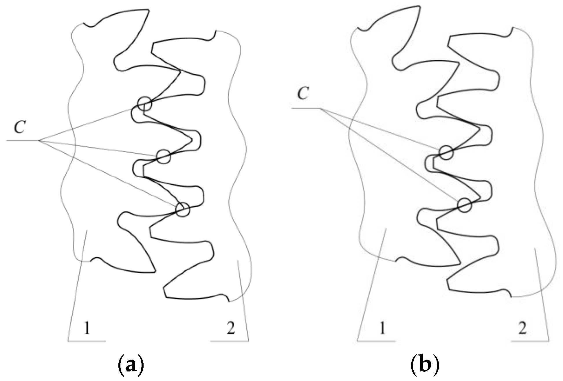
Figure 1, is characterized by the contact ratio greater than 2 and there are at least two teeth meshing at the same time. From the theory of meshing follows that the contact ratio significantly affects the distribution of the load on individual teeth and thus also the magnitude of contact pressures [
2], noise and vibration reduction [
3].
The surface bearing capacity of teeth affects the lifetime of gears [
4]. It can be increased by standard technological methods (thermal, chemical–thermal processing) or by the application of coatings deposited on the surface of teeth. Its evaluation is based on calculation standards ISO, AGMA and DIN [
5,
6]. Experimental verification is carried out either from the point of view of scuffing or pitting capacity, where contact pressures are important parameters. If coated gears are tested, the depth of the grooves on the surface of teeth is an important criterion for scuffing and it can be measured by roughness of teeth surfaces [
4,
6,
7].
Coating deposition on teeth surfaces is an effective process for increasing the lifetime of gears. This process has been researched since 1980 [
8,
9]. Nowadays the effects of contact pressures on the wear of coated gears have been mainly studied [
10,
11]. Hard TiC, WC and CrN coatings provide the resistivity against contact pressures [
12,
13,
14,
15] and MoS
2 coatings supply the excellent sliding properties [
16,
17].
The TiAlCN coatings are very promising because of high wear resistance, good sliding properties and good corrosion resistance [
18,
19,
20,
21] also at elevated temperature [
22]. They are usually deposited by PVD processes [
18,
19,
20,
21], or less frequently by CVD processes [
23]. The advantages of PVD processes include their compatibility with industry, good film adhesion, excellent stoichiometric control and low temperature [
23,
24]. The TiAlCN coatings prepared by cathodic arc deposition at a temperature below 450 °C are characterized by microhardness of 22–41 GPa [
18] and Young’s modulus of 240–300 GPa [
25]. These values could be compared to TiBC coatings with a microhardness of 18–48 GPa and Young’s modulus of 146–235 GPa deposited by thermo-reactive diffusion in temperature intervals from 1000 to 1050 °C [
26]. However, a relatively low deposition temperature of PVD processes is one of important parameters for achieving a required substrate hardness. The hardness of substrate above 55 HRC [
27] is a precondition for good resistance against high contact pressures. For this reason, TiAlCN coatings are mostly deposited on hard substrates [
28,
29,
30,
31,
32]. The gears made of structural steels are hardened, so the required substrate hardness could be easily achieved. TiAlCN coatings could also be applied on soft substrates when lower mechanical load is applied. Medical instruments [
33,
34,
35] and substrates of structural steels worn at slipping are examples for lower load [
36,
37].
The wear of TiAlCN coatings deposited on HCR gears has not yet been studied. Therefore, the aim of this study was the evaluation of the resistance of HCR gear with deposited TiAlCN coating against scuffing and characterization of its wear.
2. Materials and Methods
The HCR gears with TiAlCN coatings were used for wear testing. The ASTM A576-B1 (C55) steel was chosen for the substrate of gears. This steel contains 0.57–0.65% C, 0.5–0.8% Mn, 0.15–0.4% Si, max. 0.04% P and max. 0.04% S. Its surface was hardened using Nd YAG laser to a hardness of 60 HRC. The TiAlCN coatings were prepared by cathodic arc deposition using Platit Pl1000 equipment. Ti and TiAl (75/25) targets were used for deposition at bias 180 V and a temperature of 430 °C for 8 h in mixed atmosphere of nitrogen and acetylene. After deposition, the gears were cooled up to 20 °C in air. Long deposition time at relatively high temperature caused a decrease in substrate hardness on 43–45 HRC.
The scuffing resistance of the deposited coatings was determined by a Niemann tester which is also called the FZG test and is the equivalent of the ISO14635-1 [
38] and ASTM D5182—19 standard [
39]. Coated HCR gears consisting of the pinion with 21 teeth and the gear with 51 teeth were tested at gradual load stage which corresponded to gradually increasing torque from 2.5 Nm at the 1st load stage to 518.5 Nm at the 12th load stage. At every load stage, the pinion with 21 teeth accompanied 30,000 revolutions and the gear with 51 teeth accompanied 12,350 revolutions.
Two lubricants, OMV Biogear S150 and PP90 hydraulic oil, with the same equivalent SAE90 number were used during the tests. The OMV Biogear S150 lubricant is environmentally friendly and can be applied for bearings in agriculture machines [
40]. The PP90 hydraulic oil had universal application and was tested to verify its application in gears. Temperature increases in lubricants during the test was used as the criterion for their evaluation and it should not exceed 80 °C.
Critical scuffing load stage during the Niemann test was determined by two different criteria. The first criterion for the Niemann test evaluation corresponded to the weight loss of 10 mg in two successive load stages [
38]. This criterion is suitable mainly for gears without applied coatings [
41,
42]. The second criterion for the Niemann test evaluation corresponded to the maximal roughness of worn gear tooth surface Rz exceeding value of 7 µm. This criterion is suitable also for gears with coating as it can localize the wear on the most exposed parts of the gear tooth surface. The weight loss of the pinion, with total weigh of 1350 g, was determined using the Mettler Toledo PR2003 precision scale with the capacity of 2100 g and the resolution of 1 mg. The roughness of experimental gear teeth was measured by contact by a diamond tip using the Mitutoyo SJ-411 roughness tester.
SEM observation using JEOL JSM-IT300 microscope and EDS analysis using Oxford Instruments X-Max 20 spectrometer were used for characterization of deposited TiAlCN coatings and their wear. The wear of gear teeth was studied in three spots: on the face, pitch and flank of tooth. These spots were chosen to study the relationship between distribution of load, coating thickness, and wear extent. The measured values of roughness and wear extent were compared on the surfaces in contact with one another during meshing. Therefore, wear of the tooth pitch of the gear was compared with the tooth pitch of the pinion, the tooth face of the gear with the tooth flank of the pinion, and the tooth flank of the gear with the tooth face of the pinion.
3. Results and Discussion
3.1. Microstructure and Thickness of Applied Coatings
The TiAlCN coatings with different thicknesses are shown in cross sectional SEM images of teeth in
Figure 2 and
Figure 3. The TiAlCN coatings with their maximal thickness on the tooth face of the pinion are documented in
Figure 2. The thickness decreased towards the tooth flank with its minimal value which can be seen in
Figure 3.
The average thickness of the TiAlCN coatings was 4.4 µm on the tooth face, 2.9 µm on the tooth pitch and 1.1 µm on the tooth flank. The highest thickness of coating on the tooth face was the consequence of the most favourable conditions for the ions blasted from the cathode on this part of tooth during cathodic arc deposition. On other tooth parts, the deposition conditions were worsened by evolving incurvature which caused the decrease in layer thickness from the tooth face towards the tooth flank.
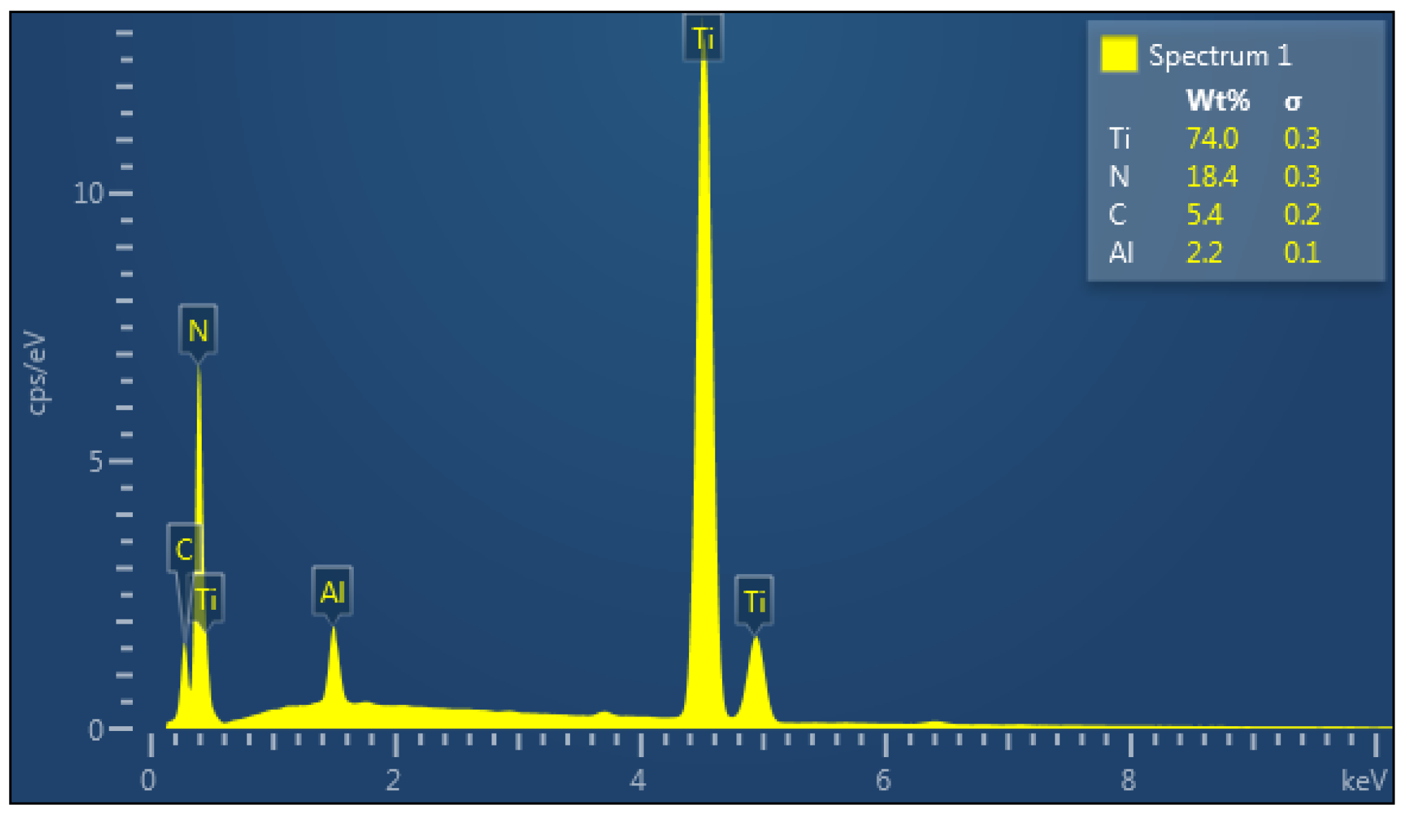
The chemical composition of the TiAlCN coatings was measured by EDS analysis on several points.
Figure 4 shows an example of this analysis from the region which is marked in
Figure 2 (Spectrum 1). The average values from all analyses were 73.5 wt.% of titanium, 18.7 wt.% of nitrogen, 5.5 wt.% of carbon and 2.3 wt.% of aluminium.
3.2. Temperature of Lubricants
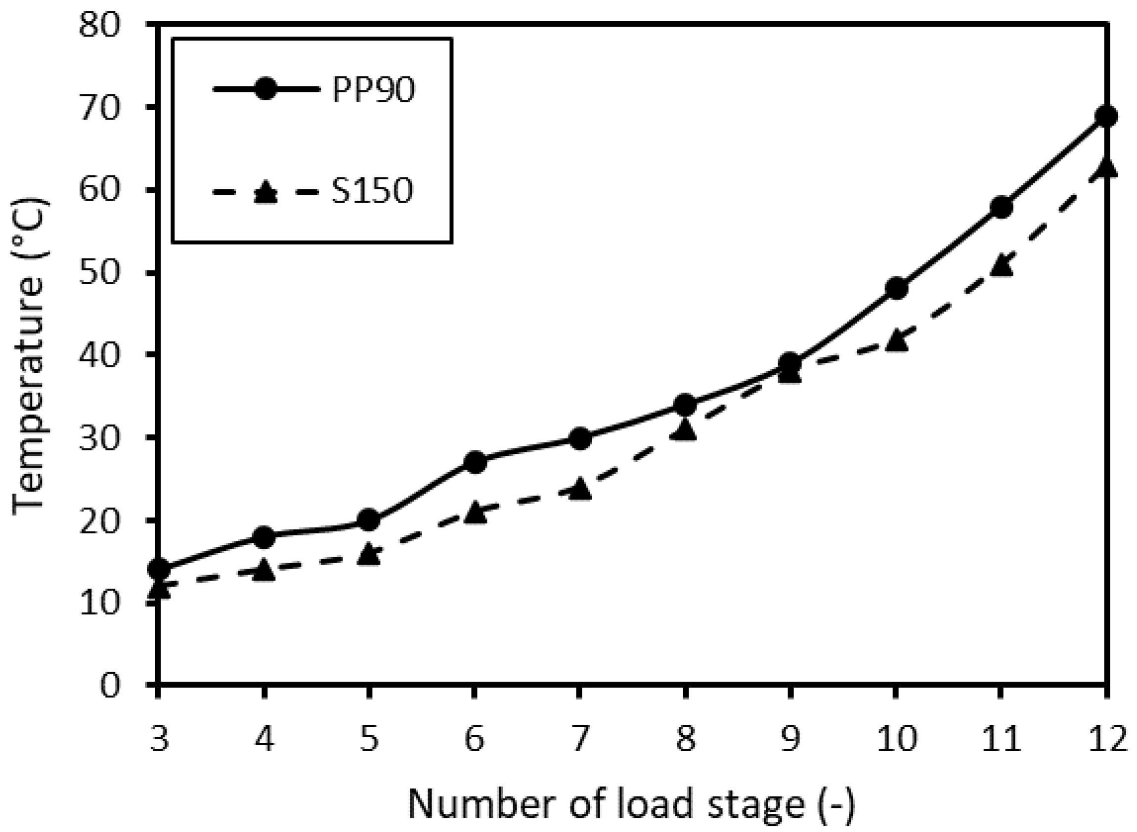
As lubricant heats during the load of a gear, the operating temperature of lubricant is its evaluation criterion, and it should not exceed 80 °C. The evolution of temperature for Biogear S150 and PP90 experimental oil is compared in
Figure 5 during the testing of gears with TiAlCN coatings. The temperature of both tested lubricants increased with loading stage during the Niemann test. The temperature of PP90 oil was slightly higher at all load stages when compared to Biogear S150 oil, but it did not exceed 70 °C at the end of the test.
3.3. Weight Loss of Gears
The weight loss exceeding 10 mg in two successive load stages during the Niemann test represents the scuffing resistance of the gear. The progress in weight loss of the pinion after different load stages and application of two different lubricants is presented in
Figure 6. The weight loss above 10 mg was measured between the 8th and 9th load stage and irrespective of the application of either lubricant, Biogear S150 or PP90 oil. A significant reduction of weight was registered between the 11th and 12th load stage.
Based on slightly better results achieved with S150 oil compared to PP90 oil (
Figure 5 and
Figure 6), the next experiments were performed only with Biogear S150 oil.
3.4. Roughness of Gear Tooth Surfaces and Their Wear
The local wear of the gear, which express its scuffing resistance, was evaluated by measuring the roughness on the tooth face, pitch and flank (
Figure 1). After every load stage, the maximal roughness Rz was measured on the pinion and gear teeth surfaces. Subsequently, average values of Rz roughness were calculated and compared with the criterion for the scuffing, the maximal roughness exceeding a value of 7 µm. The results of roughness measurements are presented in several graphs, where the pairs of gears in contact are compared respecting the following system: the tooth pitch of the gear is compared with the tooth pitch of the pinion, the tooth face of the gear is compared with the tooth flank of the pinion, and the tooth flank of the gear is compared with the tooth face of the pinion.
3.4.1. Roughness and Wear on the Tooth Pitch of Gear and on the Tooth Pitch of Pinion
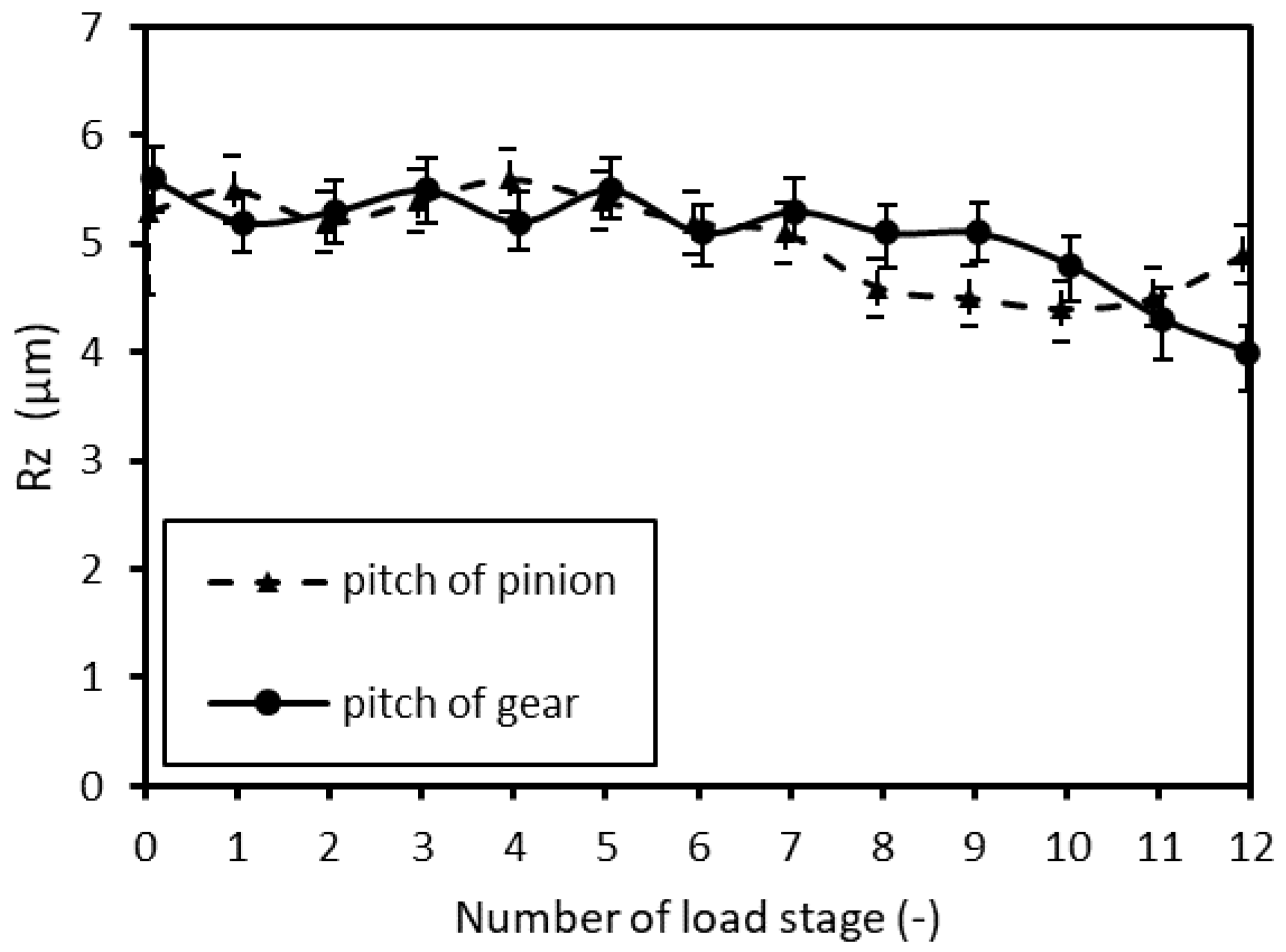
Figure 7 shows the development of average roughness Rz on the tooth pitch of the gear and pinion. The error bars in
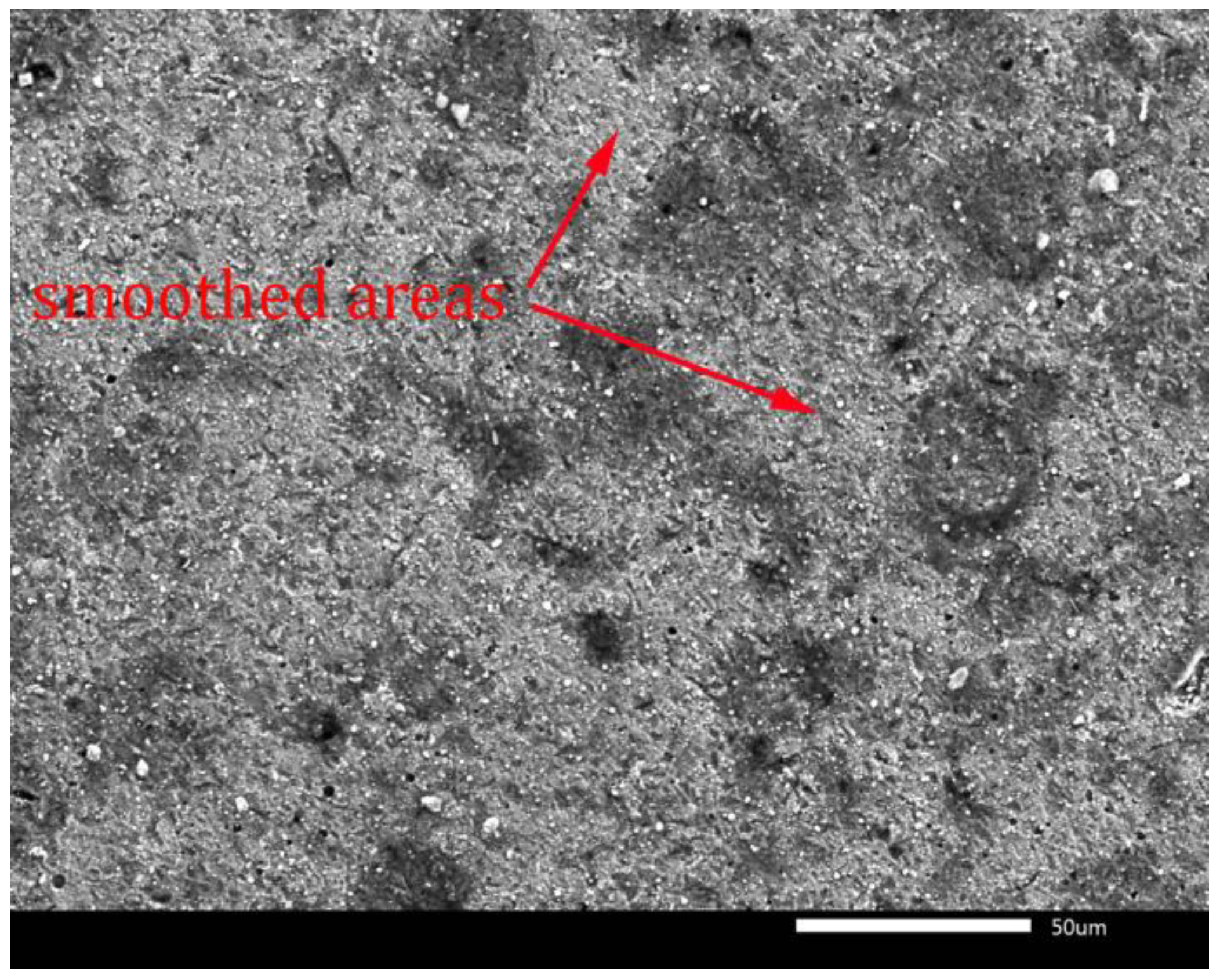
Figure 7, which represent the spread of data from 11 values, show that the measured values overlap partially, until the eighth load stage. The same average coating thickness of 2.9 µm was measured on the tooth pitch of the pinion and gear and the contact pressure is identical on both tooth pitches. The roughness on the tooth pitch of the gear with lower meshing frequency was steady up to the ninth load stage. Later, it decreased until the end of the test when it reached the minimal value of 4.0 µm. The development of roughness on the tooth pitch of the gear can be explained based on the observation of wear in the vicinity of the tooth pitch surface. During the initial stage of the test, small protrusions of deposited coatings were in contact which significantly increased the contact pressures. High contact pressures probably caused pushing the lubricant from the contact areas and in consequence of it, the wear started in conditions of dry or boundary lubricated sliding friction. The surface of the deposited TiAlCN coating was smoothed by progressive removal of coating material from layer protrusions and roughness of surface decreased up to the ninth load stage (
Figure 7). In
Figure 8, the worn surface of the gear in the vicinity of the tooth pitch is seen after the test end. Smoothed areas are marked by arrows in
Figure 8, and these were worn preferentially.
A more intensive load of the pinion in consequence of its higher meshing frequency was expressed by roughness decrease after the seventh load stage (
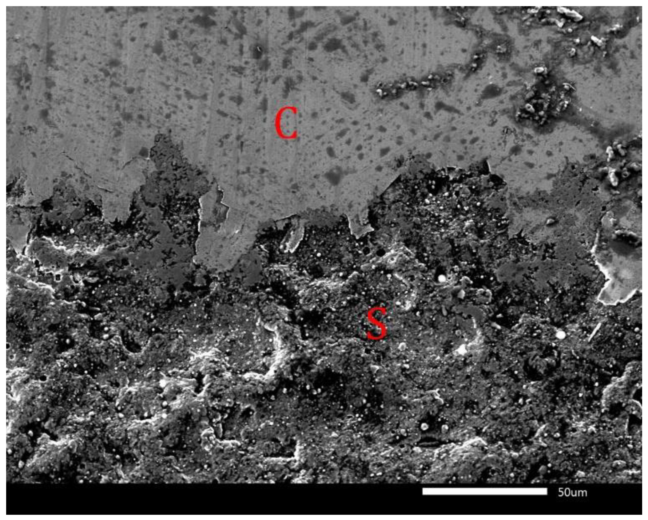
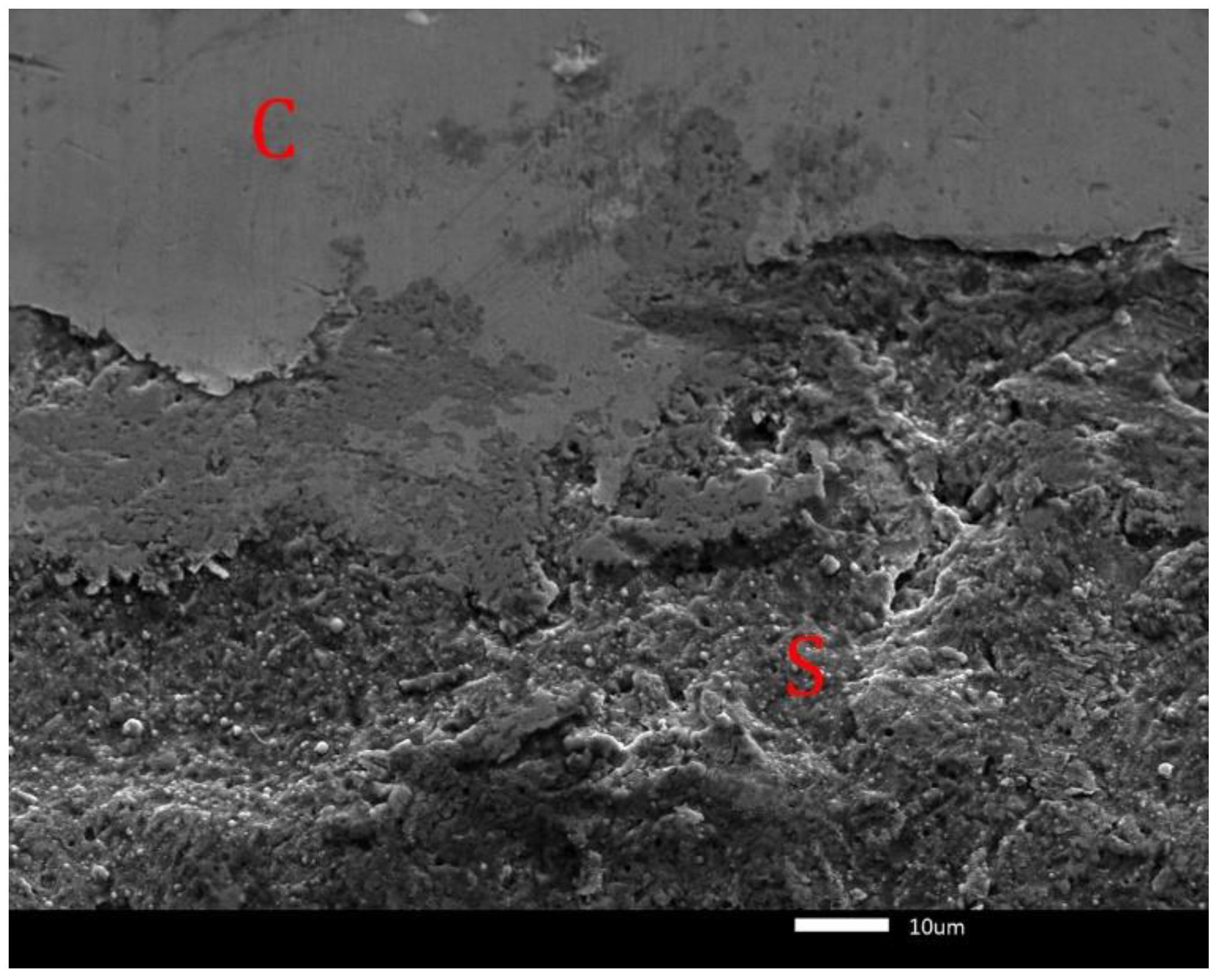
Figure 7). Roughness of pinion achieved minimal value after the 10th load stage and subsequently increased after 12th load stage to the same value as before the test. More intensive wear of the surface on the tooth pitch of the pinion compared to wear of the gear is documented in
Figure 9. The boundary between smoothed coating (C) and substrate (S) can be seen in
Figure 9.
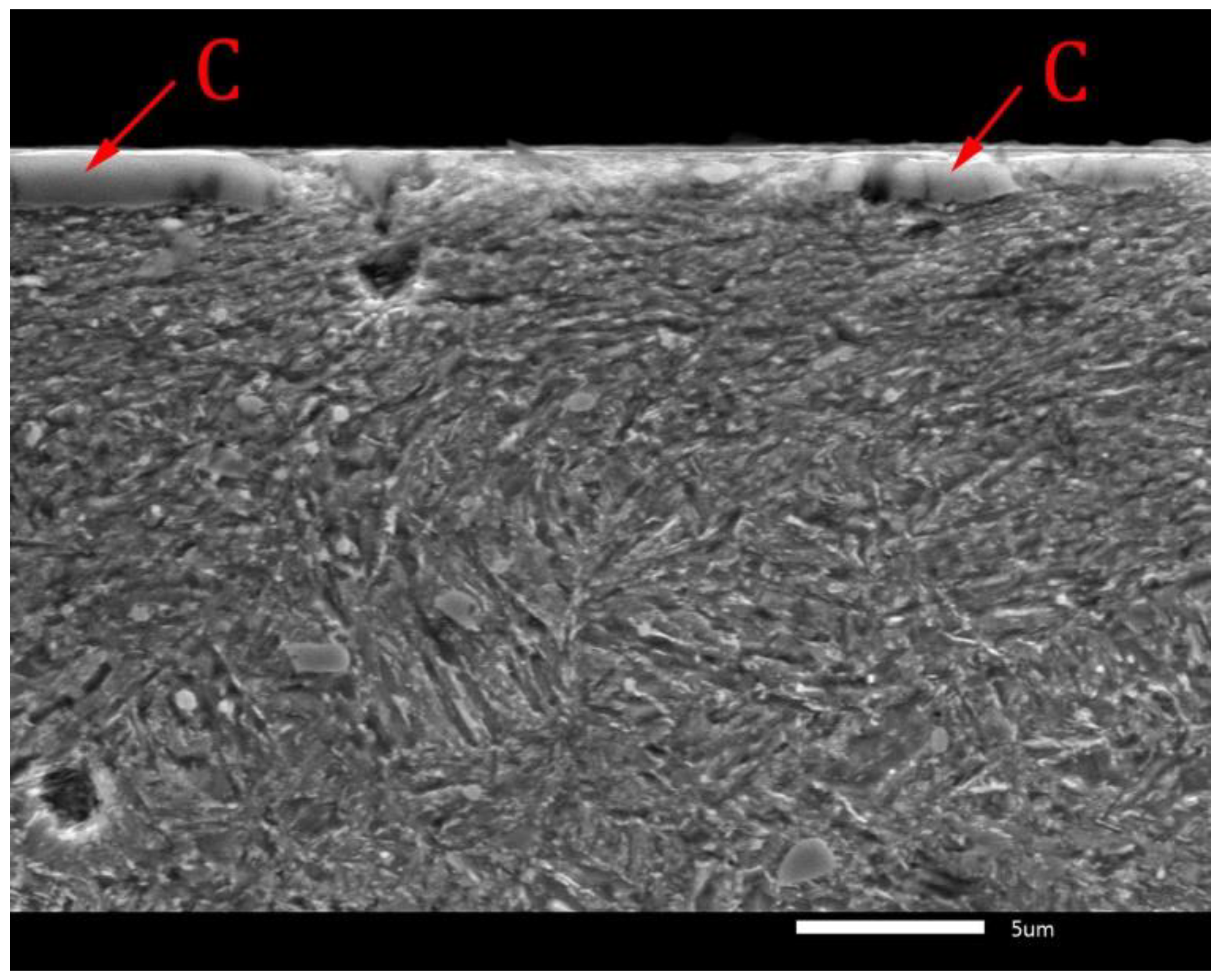
The increase in roughness after the 10th load stage was caused by detachment of smoothed layer and exposing the pinion substrate with the roughness higher than smoothed coating. The boundary between coating and substrate is visible in a cross section of the worn tooth in
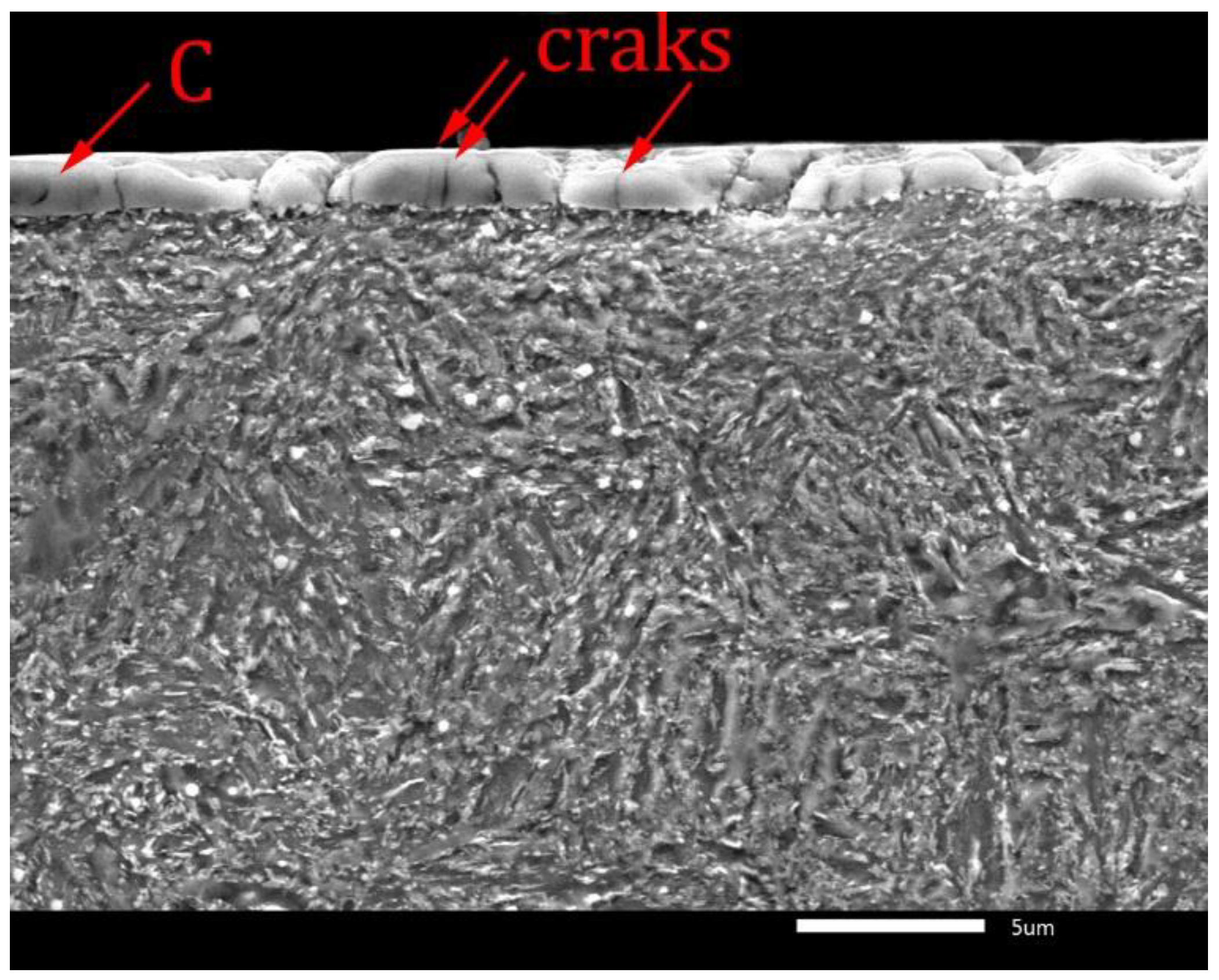
Figure 10. The coating on the tooth pitch was worn from 2.9 µm up to the thickness of about 2 µm by removal of surface protrusions in consequence of the effects of contact pressures. This thickness of the layer can be considered critical for the wear mode. It can be assumed that the layer with critical thickness was pressed in soft substrate during the subsequent load. Later, the layer cracked and its part which was nearer to the tooth flank subsequently detached. This is confirmed by both the rest of the cracked coatings in
Figure 10 and by the still compact coating with the critical thickness in
Figure 11, which is significantly cracked.
The TiAlCN coatings with a thickness above 2 µm are characterized by high scuffing resistance which made them promising for industrial applications in high speed revolution gears used, for example, in electromobiles.
3.4.2. Roughness and Wear on the Tooth Flank of Gear and on the Tooth Face of Pinion
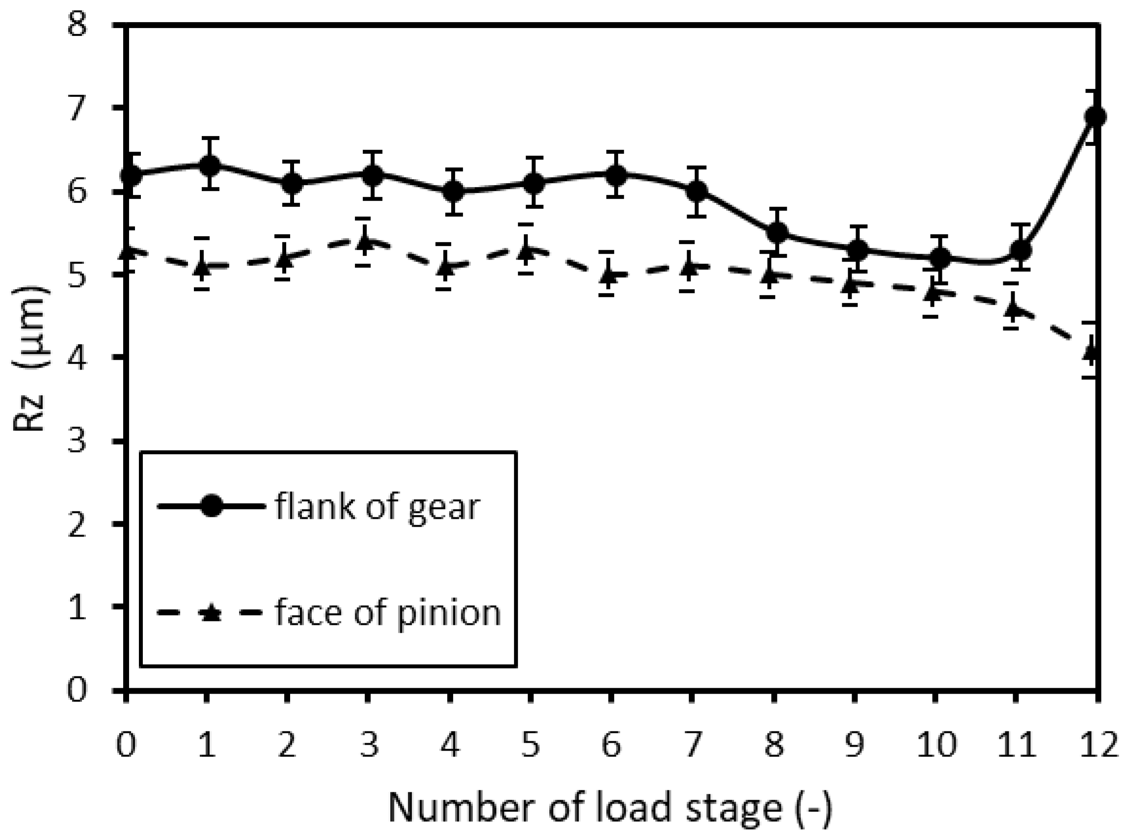
The development of roughness on the tooth flank of the gear and the tooth face of the pinion is compared in
Figure 12. The roughness values on the tooth flank of the gear are higher compared to the tooth face of the pinion even when considering the error bars in
Figure 12. The roughness of the thinner layer on the tooth flank of the gear did not change up to the seventh load stage. Later, it decreased up to the 10th load stage and subsequently increased until the end of the test. The tooth flank of the gear was worn in a similar way as the tooth pitch of the pinion. This can be seen in the boundary between the smoothed coating (C) and substrate (S) in
Figure 13. The decrease in roughness from the 7th to 10th load stage can be explained by smoothing of surface protrusions and the increase in roughness after the 10th stage is the consequence of detachment of coating from uneven substrate. The roughness of thicker TiAlCN coating on the tooth face of the pinion was steady up to the 9th load stage, and later decreased at the end of the test. The worn surface of the tooth face of the pinion (
Figure 14) had a lower portion of smoothed area on surface protrusions (marked by arrows) compared to tooth pitch of the gear (
Figure 8). This was the consequence of smaller contact pressures so there were more favourable lubrication conditions even at higher meshing frequency for the pinion compared to the gear.
3.4.3. Roughness and Wear on the Tooth Face of Gear and on the Tooth Flank of Pinion
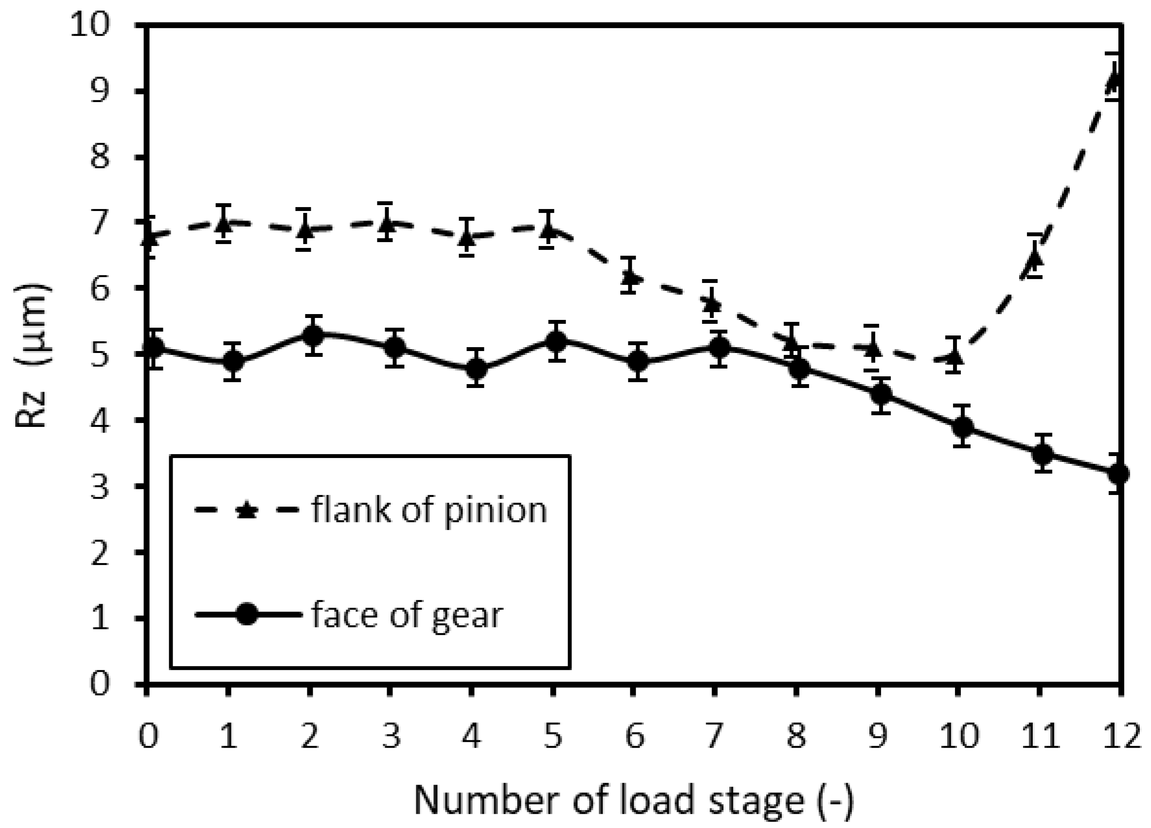
The evolution of average values of maximal roughness Rz on the tooth face of the gear and the tooth flank of the pinion, which are mostly in contact during meshing, is shown in
Figure 15. Higher roughness values on the tooth flank of the pinion, including the error bars, compared to the tooth face of the gear can be seen in
Figure 15. The roughness of thicker TiAlCN coating on the tooth face of the gear was relatively stable up to the seventh load stage, later decreased till the end of the test. The wear of TiAlCN coating on the tooth face of the gear corresponded to the wear on the tooth pitch of the gear with similar characteristics as in
Figure 8. The tooth flank of the pinion is the most intensive loaded part of whole gear mechanism because of high contact pressure and high meshing frequency. The layer thickness in this part is only 1.1 µm which is significantly below the critical thickness (2 µm) from point of view of coating detachment. The roughness of TiAlCN coating on the tooth flank of the pinion was relatively stable up to the 5th load stage, later decreased until the 10th load stage and subsequently increased until the end of the test. The development of roughness in
Figure 15 indicates that thin TiAlCN coating was removed after the 5th load stage, later until the 10th load stage, the surface protrusions on relative soft substrate were smoothed. This process was explained in our previous works [
43,
44,
45,
46]. After smoothing, the substrate was worn by cutting which can be seen in
Figure 16 where several wear grooves are marked by arrows. Significant wear of substrate was the consequence of both roughness increase in
Figure 15, and weight loss of the pinion after the 12th load stage in
Figure 6.
4. Conclusions
Wear of TiAlCN coatings deposited on HCR gears was studied using the Niemann test during which the tested gears were loaded up to the 12th load stage. The scuffing of the tested gears was evaluated based on the criteria of allowable roughness (max. Rz 7 µm) and weight loss (max. 10 mg). The extent and character of wear were influenced by coating thickness, contact pressure values and meshing frequency on loaded teeth surfaces.
Deposited TiAlCN coatings had the different thicknesses on different teeth parts. The thickest layers were measured on the teeth faces with an average value of 4.4 µm. The thicknesses of coatings decreased gradually toward the teeth flanks with their minimal values of 1.1 µm. The highest contact pressures arose during the contact of the tooth face of the gear and tooth flank of the pinion. The highest wear was observed on the tooth flank of the pinion, which had the thinnest layer and was loaded with the highest load at the highest meshing frequency.
Wear of thicker TiAlCN coating on the tooth face and tooth pitch started with the smoothing of surface protrusions. The intensity of smoothing was influenced by contact pressure values and meshing frequency of the pinion and gear. The next stage of wear was characterized by depletion of TiAlCN coating. After depletion to a thickness of about 2 µm, the layer was pressed into the soft substrate, and it subsequently cracked. During the increase in load, the layer was partially detached, but it did not cause the increase in Rz roughness of layer surface above the critical value of 7 µm.
The deposited thinner TiAlCN coating on the tooth flank cracked and detached at lower load stages compared to the thicker layer. After total delamination of the layer, the relative soft substrate of the pinion tooth was worn by cutting, which caused Rz roughness increase in surface layer above the critical value of 7 µm and weight loss surpassing 10 mg which are the parameters representing wear by scuffing.
Author Contributions
Conceptualization, P.Š., M.B. and E.G.; methodology, P.Š.; software, R.P.; validation, M.B., E.G., P.Š. and Ľ.M.; investigation, E.G and P.Š.; resources, Ľ.M.; data curation, P.Š.; writing—original draft preparation, E.G.; writing—review and editing, P.Š.; visualization, R.P.; supervision, P.Š.; project administration, M.B. All authors have read and agreed to the published version of the manuscript.
Funding
This research was supported by Slovak Grant Agency within the project APVV-19-0401, and by Slovak Research Agency within the project ITMS+313011V334.
Conflicts of Interest
The authors declare no conflict of interest. The funders had no role in the design of the study; in the collection, analyses, or interpretation of data; in the writing of the manuscript; or in the decision to publish the results.
References
- Vereš, M.; Bošanský, M.; Gaduš, J. Theory of Convex-Concave and Plane Cylindrical Gearing; STU Bratislava: Bratislava, Slovakia, 2006; ISBN 80-227-2451-3. [Google Scholar]
- Goldfarb, V.; Trubachev, E.; Barmina, N. Advanced Gear Engineering; Springer: Basel, Switzerland, 2018; ISBN 978-3-319-60398-8. [Google Scholar]
- Žiaran, S.; Darula, R. Determination of the State of Wear of High Contact Ratio Gear Sets by Means of Spectrum and Cepstrum Analysis. J. Vib. Acous. 2013, 135, 021008. [Google Scholar] [CrossRef]
- Moorthy, V.; Shaw, B. Contact fatigue performance of helical gears with surface coatings. Wear 2012, 276–277, 130–140. [Google Scholar] [CrossRef]
- ISO 6336-2; Calculation of load capacity of spur and helical gears—Part 2: Calculation on surface durability. International Organization for Standardization: Geneva, Switzerland, 2006.
- Janna, S.; Lin, H.H. Comparison of spur gear root stress calculation. In Proceedings of the ASME 2005 International Mechanical Engineering Congress and Exposition, Orlando, FL, USA, 5–11 November 2005; pp. 637–653. [Google Scholar] [CrossRef]
- Juoksukangas, J.; Hintikka, J.; Lehtovaara, A.; Mäntylä, A.; Vaara, J.; Frondelius, T. Avoiding the initial adhesive peak in fretting. Wear 2020, 460–461, 203353. [Google Scholar] [CrossRef]
- Christy, R.I. Dry lubrication for rolling element spacecraft parts. Tribol. Int. 1982, 15, 265–271. [Google Scholar] [CrossRef]
- Terauchi, Y.; Nadano, H.; Kohno, M.; Nakamoto, Y. Scoring resistance of TiC- and TiN-coated gears. Tribol. Int. 1987, 20, 248–254. [Google Scholar] [CrossRef]
- Ballesteros-Arguello, A.; Ramírez-Reyna, F.O.; Rodríguez-Castro, G.A.; Meneses-Amador, A.; Fernández-Valdés, D.; Reyes-Carcano, O. Experimental and numerical evaluation of the contact fatigue resistance of AlCrN, FexN and AlCrN/ FexN coatings on AISI 4140 steel. Surf. Coat. Technol. 2021, 423, 127620. [Google Scholar] [CrossRef]
- Rinawa, M.L.; Sharma, R.; Baviskar, P.R.; Sampathkumar, R.; Deshmukh, R.G.; Rao, M.V.; Subbiah, R. Study of wear properties of aluminium alloy for different mass of SiC particles. Mater. Today Proc. 2022, 62, 5218–5222. [Google Scholar] [CrossRef]
- Muvvala, G.; Karmakar, D.P.; Nath, A.K. Online assessment of TiC decomposition in laser cladding of metal matrix composite coatings. Mater. Des. 2017, 121, 310–320. [Google Scholar] [CrossRef]
- Voorwald, H.J.C.; Souza, R.C.; Pigatin, W.L.; Cioffi, M.O.H. Evaluation of WC–17Co and WC–10Co–4Cr thermal spray coatings by HVOF on the fatigue and corrosion strength of AISI 4340 steel. Surf. Coat. Technol. 2005, 190, 155–164. [Google Scholar] [CrossRef]
- Gong, T.; Yao, P.; Zuo, X.; Zhang, Z.; Xiao, Y.; Zhao, L.; Zhou, H.; Deng, M.; Wang, Q.; Zhong, A. Influence of WC carbide particle size on the microstructure and abrasive wear behaviour of WC–10Co–4Cr coatings for aircraft landing gear. Wear 2016, 362–363, 135–145. [Google Scholar] [CrossRef]
- Benedetti, M.; Fontanari, V.; Torresani, E.; Girardi, C.; Giordanino, L. Investigation of lubricated rolling sliding behaviour of WC/C, WC/C-CrN, DLC based coatings and plasma nitriding of steel for possible use in worm gearing. Wear 2017, 378–379, 106–113. [Google Scholar] [CrossRef]
- Martins, R.; Amaro, R.; Seabra, J. Influence of low friction coatings on the scuffing load capacity and efficiency of gears. Tribol. Int. 2008, 41, 234–243. [Google Scholar] [CrossRef]
- Yang, Y.; Fan, X.; Yue, Z.; Li, W.; Li, H.; Zhu, M. Synergistic lubrication mechanisms of molybdenum disulfide film under graphene-oil lubricated conditions. App. Surf. Sci. 2022, 598, 153845. [Google Scholar] [CrossRef]
- Jang, C.S.; Jeon, J.H.; Song, P.K.; Kang, M.C.; Kim, K.H. Synthesis and mechanical properties of TiAlCxN1-x coatings deposited by arc ion plating. Surf. Coat. Technol. 2005, 200, 1501–1506. [Google Scholar] [CrossRef]
- Falub, C.V.; Karimi, A.; Ante, M.; Kalss, W. Interdependence between stress and texture in arc evaporated Ti–Al–N thin films. Surf. Coat. Technol. 2007, 201, 5891–5898. [Google Scholar] [CrossRef]
- Basnyat, P.; Luster, B.; Muratore, C.; Veovodin, A.A.; Haasch, R.; Zakeri, R.; Kohli, P.; Aouadi, S.M. Surface texturing for adaptive solid lubrication. Surf. Coat. Technol. 2008, 203, 73–79. [Google Scholar] [CrossRef]
- Endler, I.; Hohn, M.; Herrmann, M.; Holzschuh, H.; Pitonak, R.; Ruppi, S.; van der Berg, H.; Westphal, H.; Wilde, L. Aluminum-rich TiAlCN coatings by low pressure CVD. Surf. Coat. Technol. 2010, 205, 1307–1312. [Google Scholar] [CrossRef]
- Jyothi, J.; Chaliyawala, H.; Srinivas, G.; Nagaraja, H.S.; Barshilia, H.C. Design and fabrication o spectrally selective TiAlC/TiAlCN/TiAlSiCN/TiASiCO/ TiAlSiO tandem absorber for high-temperature solar thermal power applications. Sol. Energy Mater. Sol. Cells 2015, 140, 209–216. [Google Scholar] [CrossRef]
- Chen, Y.; Mei, F.; Lin, X.; Zhang, H.; Gao, J.; Yuan, T.; Li, R.; Peng, T. The effect of carbon doping on microstructure, mechanical properties, wear resistance and cutting performance of AlTiCN coating. Thin Solid Films 2020, 713, 138344. [Google Scholar] [CrossRef]
- Dhoble, S.J.; Kalyani, N.T.; Vengadaesvaran, B.; Arof, A.K. Energy Materials: Fundamentals to Applications, 1st ed.; Elsevier: Amsterdam, The Netherlands, 2021; ISBN 978-0128237106. [Google Scholar]
- Li, X.; Li, G.; Lu, W.; Liu, S.; Li, C.; Wang, Q. Controllable high adhesion and low friction coefficient in TiAlCN coatings by tuning C/N ratio. App. Surf. Sci. 2022, 597, 153542. [Google Scholar] [CrossRef]
- Kurt, B.; Özdoğan, L.; Güney, B.; Bölükbasi, Ö.S.; Günen, A. Characterization and wear behavior of TiBC coatings formed by thermos-reactive diffusion technique on AISI D6 steel. Surf. Coat. Technol. 2020, 385, 125332. [Google Scholar] [CrossRef]
- Stewart, S.; Ahmed, R. Rolling contact fatigue of surface coatings—A review. Wear 2002, 253, 1132–1144. [Google Scholar] [CrossRef]
- D´Errico, G.E.; Guglielmi, E.; Rutelli, G. A study of coatings for end mills in high speed metal cutting. J. Mater. Process. Technol. 1999, 92–93, 251–256. [Google Scholar] [CrossRef]
- Hsu, C.H.; Lee, C.Y.; Lee, C.C. Analysis on the corrosion behaviour of DC53 tool steel coated by Ti–Al–C–N films via filtered cathodic arc deposition. Thin Solid Films 2009, 517, 5212–5215. [Google Scholar] [CrossRef]
- Al-Bukhaiti, M.A.; Al-hatab, K.A.; Tillmann, W.; Hoffmann, F.; Sprute, T. Tribological and mechanical properties of Ti/TiAlN/TiAlCN nanoscale multilayer PVD coatings deposited on AISI H11 hot work tool steel. App. Surf. Sci. 2014, 318, 180–190. [Google Scholar] [CrossRef]
- Dong, W.; Xu, L.; Wen, J.; Lin, Q.; Wang, Z. Galling mechanism in metal forming process with TRD coated die against advanced high strength steel sheet. Procedia Eng. 2017, 207, 2233–2238. [Google Scholar] [CrossRef]
- Vereschaka, A.; Tabakov, V.; Grigoriev, S.; Sitnikov, N.; Milovich, F.; Andreev, N.; Sotova, C.; Kutina, N. Investigation of the influence of the thickness of nanolayers in wear-resistant layers of Ti-TiN- (Ti,Cr,Al)N coating on destruction in the cutting and wear of carbide cutting tools. Surf. Coat. Technol. 2020, 385, 125402. [Google Scholar] [CrossRef]
- Suoto, R.M.; Alanyali, H. Electrochemical characteristics of steel coated with TiN and TiAlN coatings. Corros. Sci. 2000, 42, 2201–2211. [Google Scholar] [CrossRef]
- Mejía, H.D.; Echavarría, A.M.; Calderón, J.A.; Bejarano, G. Microstructural and electrochemical properties of TiAlN (Ag,Cu) nanocomposite coatings for medical applications deposited by dc magnetron sputtering. J. Alloys Compd. 2020, 828, 154396. [Google Scholar] [CrossRef]
- Geyao, L.; Yang, D.; Wanglin, C.; Chengyong, W. Development and application of physical vapor deposited coatings for medical devices: A review. Procedia CIRP 2020, 89, 250–262. [Google Scholar] [CrossRef]
- Larbi, A.B.C.; Tlili, B. Fretting wear of multilayered PVD TiAlCN/TiAlN/TiAl on AISI 4140 steel. Surf. Coat. Technol. 2006, 201, 1511–1518. [Google Scholar] [CrossRef]
- Zhang, X.; Jiang, J.; Yugiao, Z.; Lin, J.; Wang, F.; Moore, J.J. Effect of carbon on TiAlCN coatings deposited by reactive magnetron sputtering. Surf. Coat. Technol. 2008, 203, 594–597. [Google Scholar] [CrossRef]
- ISO 14635-1:2000; Gears—FZG test procedures. International Organization for Standardization: Geneva, Switzerland, 2000.
- ASTM D5182-19; Standard Test Method for Evaluating the Scuffing Load Capacity of Oils (FZG Visual Method). ASTM International: West Conshohocken, PA, USA, 2019.
- Rusnák, J.; Kadnár, M.; Kučera, M. Biologicky Odbúrateľné Oleje; SPU Nitra: Nitra, Slovakia, 2009; ISBN 978-80-552-0166-5. [Google Scholar]
- Terleeva, P.; Slonova, A.I.; Rogov, A.B.; Yerokhin, A. Wear resistant coatings with a high friction coefficient produced by plasma electrolytic oxidation of Al alloys in electrolytes with basalt mineral powder additions. Materials 2019, 12, 2738. [Google Scholar] [CrossRef] [PubMed]
- Mahade, S.; Narayan, K.; Govindarayan, S.; Bjorklund, S.; Curry, N.; Joshi, S. Exploiting Suspension Plasma Spraying to Deposit Wear-Resistant Carbide Coatings. Materials 2019, 12, 2344. [Google Scholar] [CrossRef] [PubMed]
- Bošanský, M.; Gondár, E.; Švec, P.; Toth, F.; Protasov, R. A Study of Wear in Thin Coatings Applied to Convex-Concave Gearings. Lubricants 2020, 8, 56. [Google Scholar] [CrossRef]
- Švec, P.; Bošanský, M.; Gondár, E.; Toth, F.; Protasov, R. Wear of AlCrN and CrAlSiN coatings applied to nonstandard involute gears. Lubricants 2021, 9, 54. [Google Scholar] [CrossRef]
- Gondár, E.; Bošanský, M.; Rusnák, J.; Toth, F.; Repková, J. The Application of DLC Coating on Convex-Concave (C-C) Gearings. Manuf. Technol. 2019, 19, 930–935. [Google Scholar] [CrossRef]
- Gondár, E.; Bošanský, M.; Repková, J.; Toth, F. The carrying capacity of TiCN coating on convex-concave (C-C) gearings. MM Sci. J. 2018, 18, 2633–2638. [Google Scholar] [CrossRef]
| Publisher’s Note: MDPI stays neutral with regard to jurisdictional claims in published maps and institutional affiliations. |
© 2022 by the authors. Licensee MDPI, Basel, Switzerland. This article is an open access article distributed under the terms and conditions of the Creative Commons Attribution (CC BY) license (https://creativecommons.org/licenses/by/4.0/).
