Article

Evaluation and Application of an Engineering Calculation Method of the Static Performance of an Aerostatic Journal Bearing with Multiple Orifice-Type Restrictors

Center for Precision Engineering, Harbin Institute of Technology, Harbin 150001, China
*
Author to whom correspondence should be addressed.
Lubricants 2022, 10(12), 332; https://doi.org/10.3390/lubricants10120332
Submission received: 13 October 2022 / Revised: 14 November 2022 / Accepted: 21 November 2022 / Published: 24 November 2022
(This article belongs to the Special Issue Tribological Characteristics of Bearing System)

Abstract

:
A simplified calculation method is evaluated to calculate the static performance of an aerostatic journal bearing with multiple orifice-type restrictors. This method adopts a one-dimension flow assumption and is a fast calculation method to design journal bearings in engineering by directly linking the structural parameters and performance parameters affecting radial bearings with nonlinear equations. In addition, this method is verified with computational fluid dynamics by two actual case studies, and it is found that the LCC difference between those two methods is less than 5% for a 200 mm diameter spindle, and less than 10% for a 100 mm diameter spindle. Subsequently, the influence of a key parameter   ζ i   on the static performance of journal bearings is explained theoretically. This method is much easier and more intuitive compared with numerical computational methods. Furthermore, it promotes the application of aerostatic journal bearings.

1. Introduction

Owing to the absence of mechanical contact between moving parts, it is possible to obtain extremely high accuracy and high speed from a motion system when supported by aerostatic bearing. Therefore, aerostatic bearings have been commonly utilized in positioning systems, and precision machining equipment, etc. [1,2,3]. Most of the film flow field can be directly described by the Reynolds equation; therefore, the core work of gas bearing performance calculation is to solve the Reynolds equation according to the given input parameters (geometry, lubricant properties, working conditions, boundary conditions, etc.). The basic problem of fluid-film lubricated bearings is to determine the pressure distribution under various working conditions. On the basis of obtaining the pressure distribution, the performance parameters of the bearing, such as stiffness and load carrying capacity (LCC), which are of great importance during and after the design, can be obtained by integrating/differentiating the pressure field on the air film surface.
Lots of calculation methods have been suggested to address the nonlinear Reynolds equation governing pressure distribution in aerostatic bearing and static performance [4,5,6]. In addition to these computational methods for solving the general Reynolds equation, there have been many developments in computational methods for aerostatic bearings with external restrictors. There are two methods for solving the characteristics of aerostatic bearings: analytical and numerical. The analytical solution can roughly obtain the bearing characteristics, point out important variables and parameters, narrow the scope of the attention of variables, and help to intuitively understand the physical situation. Powell proposed the gauge-pressure ratio method, which gives the formula for the static performance of aerostatic bearings [7]. The gauge-pressure ratio method borrows the symbol of hydrostatic bearings, and the compressibility of gas is not properly handled, so it is necessary to manually consult the table to obtain the bearing characteristics. Li et al. described a simplified calculation method of aerostatic thrust bearing with multiple pocketed orifice-type restrictors (MPOTRs); however, this simplified model has not been discussed for aerostatic journal bearing [8]. Tang and Gross summarized the one-dimensional flow model for thrust and journal bearings in the early stage of the development of lubrication mechanics, but it is limited by computer performance and lacks further analysis of key processes [9]. Jason described the same flow model for journal bearings with one-row orifices [10]. Belforte et al. presented two lumped-parameter models to rapidly obtain the static characteristic of gas bearings [11]. It is worthwhile to mention that since the steady-state Reynolds equation in a constant-thickness gas film region is the Laplace equation, Mori et al. used the complex potential method to obtain an analytical formula for radial bearing, the porous planar thrust bearing and the air-floating pad without eccentricity [12,13].
The above engineering calculation method is still widely used, but it can only solve the approximate calculation problem of the regular geometric boundary and the thickness of the gas film. To obtain more accurate prediction results, numerical methods such as the finite element method (FEM) and finite difference method (FDM) have developed with the rise in computer technology. Using the variational principle of operator equations, Reddi deducted the direct and incremental variational formulations of two-dimensional incompressible and compressible steady-state Reynolds equations, and applied FEM to the thin-film lubrication problem for the first time [14,15]. After that, Wadhwa and Nguyen et al. further developed the relevant theory of FEM to solve the performance of gas dynamic pressure bearing [16,17]; Wang and co-workers presented a computational method for solving the isothermal compressible Reynolds equation to estimate mass flow rate (MFR), friction and LCC. They linearized the Reynolds equation with the Newton method and solved it using an iterative successive relaxation method [18]. Lo and colleagues proposed a finite element method to evaluate the performance of a high-speed gas journal bearing. The dimensionless Reynolds equation was derived from the simplified dimensionless Navier-Stokes (NS) equations, discretized using the Newton method and solved by means of an iterative cutting procedure [19]. Wadhwa and Cui calculated the static characteristics of common double-row orifice radial bearings [20,21]. Li et al. calculated the static characteristics of the orifice-type aerostatic guideway [22]. Charki and Cui solved the static characteristics of the orifice-type aerostatic ball bearings [23,24]. Wu et al. found that inappropriate boundary settings can cause significant numerical errors if the grid-dependent condition is ignored, and their calculation results reveal that those numerical models with a single-source node are grid-dependent, and auxiliary sources have proved to be an effective technique to reduce single-source numerical error [25]. Chen et al. analyzed the impact on the bearing of orifice blockage in actual working conditions; the air film pressure distribution, load capacity, and tilting moment were obtained and simulation results indicate that the air film pressure decreases significantly in the blocked area of adjacent orifices [26]. In addition, Rajdeep et al. seems to be the first to solve the Reynolds equation adopting the finite volume method [27].
In addition to only calculating the air film area, computational fluid dynamics (CFD) has also been introduced to figure out bearings’ performance precisely because it solves NS equations rather than the Reynolds equation, which takes all the air paths including inlet ports, orifices, and air films into consideration. Cui et al. used Fluent software to calculate the static performance of porous aerostatic thrust bearings [28]. Wu et al. simulated the static performance of radial and thrust orifice-type bearings in a spindle designed for ultra-precision machine tools [29]. Belforte et al. gave a practical flow correction coefficient formula of small holes through CFD simulation and experiments, and unified the flow calculation method of self-contained and orifice restriction [30,31,32,33]. Renn, Yoshimoto, Eleshaky and Chang et al. carried out simulations or experiments on the static characteristics of a single-hole restriction thrust bearing [34,35,36,37], aiming to understand what happened between the region of orifice and gas film. Ting et al. utilized a CFD software to evaluate the performance of a radial–axial integrated cup-shaped aerostatic bearing for the miniature turbine of a dental handpiece [38], and Li et al. presented and simulated a novel aerostatic bearing with back-flow channels, which are designed to connect the feed pocket and low-pressure region of the bearing clearance directly [39]. CFD is of high computational accuracy, but it is time-consuming to model, computationally inefficient, and sometimes plagued by stability problems. A recent developing hybrid modeling method was proposed by Neves, Chen and Song, which uses CFD to accurately simulate the performance of orifice, and, at the same time, makes full use of FEM to efficiently calculate the Reynolds equation [40,41,42].
When it comes to numerical methods, complicated iterations are needed, the calculating procedure is sophisticated, and the calculating process is time-consuming, which makes it complex and burdensome to analyze the effect of a bearings’ parameters on its performance on account of the non-intuitiveness of the calculation process [43]. In comparison, with FEM, it is a little easier to optimize a bearing’s parameters more conveniently, but FEM requires regenerating meshes and rearranging the program with varying design parameters [44].
In this study, a simplified calculation method is proposed to simplify the calculation of pressure in aerostatic journal bearing with MPOTRs, and the influence of the bearing’s parameters on its performance is explored. Additionally, an aerostatic bearing with specific parameters is calculated by CFD to verify the method. Furthermore, the effect of ζi on a bearing’s performance section is used to determine the impact of the bearing’s parameters on its performance, and some conclusions are given.

2. Principle of the Simplified Calculation Method

Figure 1 shows an aerostatic journal bearing with MPOTRs. Both ends of external circumference with diameter D are open. Hence, 2 atmospheric boundaries are found. L is the total length where gas film exists, l is the distance between N orifices’ location and gas film edge. To ensure that the restrictor area is orifice sectional area, the air chamber is connected to the orifice. A diffusion effect is observed immediately when the gas effuses out of an orifice and the gas distribution becomes gradually uniform. Diffusion effect can be ignored if the orifices are linked by grooves [45]. In addition, a detailed description of orifice can be found in [46].
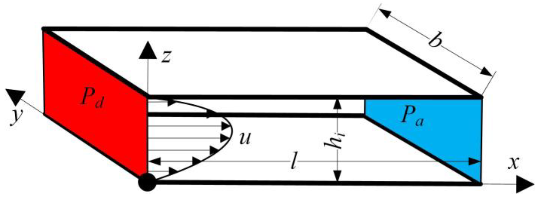
To simulate a genuine situation, the following assumptions were made in the simplified calculation method. There is no flow in the circumferential direction. In other words, the gas can distribute uniformly in every 2 π / N section edge and the pressure from Pd decreases to Pa smoothly. Lubricant gas appears to be ideal gas, which is compressible and isothermal, because the heat transfer between gas and solid could be neglected. The gas inside bearing is of low Reynolds number in the clearance because the film thickness h 0 is within tens of micrometers. Therefore, the cylindrical area can expand into a rectangle, which makes the 3-D cylindrical surface problem into a plane problem. The width b of 1-D gas film in Figure 2 is equal to π D / N in Figure 1.
According to the assumptions above, the bearing pressure P can satisfy Equations (1)–(3) in the Cartesian coordinates displayed in Figure 1 and Figure 2.
P x = η 2 u z 2
P y = 0  
P z = 0  
Equations (2) and (3) demonstrate that P is not connected to y and z. Thus, Equation (1) is expressed as
d P d x = η d 2 u d z 2  
Equation (4) is the simplified Reynolds equation under 1-D hypnosis. Supposing the film thickness in each section of the bearing surface is the same, MFR of ith section is
m ˙ i = A o P 0 2 ρ a P a φ ( β i )  
where A0 is the section area of orifice A o = π d 0 2 / 4 , and discharge correction factor   is 0.8 if the lubricant is air. Considering that the flow is isothermal, the discharge coefficient   φ under both supersonic and subsonic conditions is calculated based on Equation (6) [38].
φ ( β i ) = k k     1 β i 2 k     β i k + 1 k 1 2 ,   β i   >   β α k 2 2 k + 1 k + 1 k     1 1 2   ,   β i     β α
where k = 1.4 if lubricant is air. Β i = P di / P 0 , where P d i is the gas pressure at the ith orifice outlet. Β α = 2 / k   + 1 ( k + 1 / k     1 ) . Conclusion could be obtained from Equations (5) and (6) that MFR of each section can be assessed by β i . Based on the mass conservation law, MFR inside of 1-D gas film shown in Figure 2 can be written as
m ˙ i = b 0 h i ρ u d z  
where h i = h 0 ( 1     ε cos   θ i ) .
Equations (5) and (7) describe the mass conservation equations of the gas that flows through the bearing. Under isothermal conditions, the gas state equation is
P ρ = P a ρ a
Given that the velocity of the bearing’s surface is relatively low, when z = 0 and z = h i , u is expected to be zero for simplicity. Subsequently, u is calculated by double integration of Equation (4)
u = 1 2 η d P d x z ( h i     z )  
Equation (9) is used to substitute u in Equation (7). Then, MFR through a section with width b is derived as
m ˙ i = ρ bh i 3 12 d P d x
Considering Equation (8), ρ can be put into Equation (10), and the variables P and x are separated,
P d P = 12 η   m ˙ i P a bh i 3 ρ a x   ( 0   <   x   <   l )  
Equation (10) is integrated; the bearing’s pressure P can be calculated as
P 2 P di 2 = 24 η   m ˙ i P a bh i 3 ρ a x
Given the boundary conditions, P = Pa when x = l, Equation (12) can be written as
P a 2 P di 2 = 24 η   m ˙ i P a bh i 3 ρ a l    
Equation (12) is divided by Equation (13); P is defined as
P = P di 2     P di 2   P a 2 x l  
To obtain LCC, every section is considered separately. The pressure distribution in ith section is integrated,
F i = D 2 π N π N 2 0 l P d x + P di ( L     2 l ) cos θ   d θ  
In every section, the composition of forces generated from pressure is symmetrical about the axial line on the gas film through ith orifice, which leads to
F i = D sin π N 2 0 l P d x + P di ( L     2 l )
Equation (14) is substituted into Equation (16) and the integral value calculated,
F i = D L P 0 K i sin π N ,   K i = β i ( L     2 l ) L + 4 3 l L 1     ( σ β i ) 3 1     ( σ β i ) 2
where σ =   P a / P 0 .
The direction of F i is at a certain angle θ i = 2 i   -   1 π / N with the vertical direction, all those forces in the vertical direction are combined, LCC of the gas film can be expressed as
W = i = 1 N F i cos θ i = D L P 0 sin π N i = 1 N K i cos θ i
LCC coefficient (LCCE) can be expressed as
C W = W D L P 0 = sin π N   i = 1 N K i cos θ i
It is LCC of unit area. When bearing clearance is equal everywhere hi = h0, Ki in every section is equal and Cw must be equal to zero, indicating that bearing bears nothing.

3. Calculation Procedures of the Simplified Calculation Method

β i   is an unknown variable in Equation (17). However, the mass conservation law indicates the inflow MFR must equal to the outflow MFR, suggesting that the m ˙ i in Equations (5) and (13) must be equal:
β i 2 σ 2 σ φ = A o N h i 3 12 η π 2 P a ρ a 2 l D  
Supposing
ζ i = β i 2   -   σ 2 σ φ
and
f 1 i = A o N h i 3
f 2 = 12 η π 2 P a ρ a  
f 3 = 2 l D  
The definitions of f1i, f2 and f3 are very intuitive to understand: f1i is the gas channel coefficient related to film thickness and orifice diameter. f2 is the lubricant physical coefficient only related to the physical properties of lubricant itself, which is a constant for specific kind of gas. f3 is the bearing structural coefficient related to structural parameters. For every section, Equations (21)–(24), Equation (20) can be denoted as
ζ i = f 1 i   f 2   f 3  
If atmospheric pressure, supply pressure, lubricant gas and structural parameters are stated, ζ i   and β i are determined by Equations (25) and (21), respectively. Subsequently, LCC and LCCE are calculated by incorporating β i in Equations (18) and (19).
Given that β i and   ζ i   are associated with each other by a nonlinear univariate equation, lots of simile solution methods can be used to solve Equation (25). Figure 3 demonstrates the detailed procedures of simplified calculation method, where Kw = Δ W / Δ h   is the bearing stiffness along the radial direction.
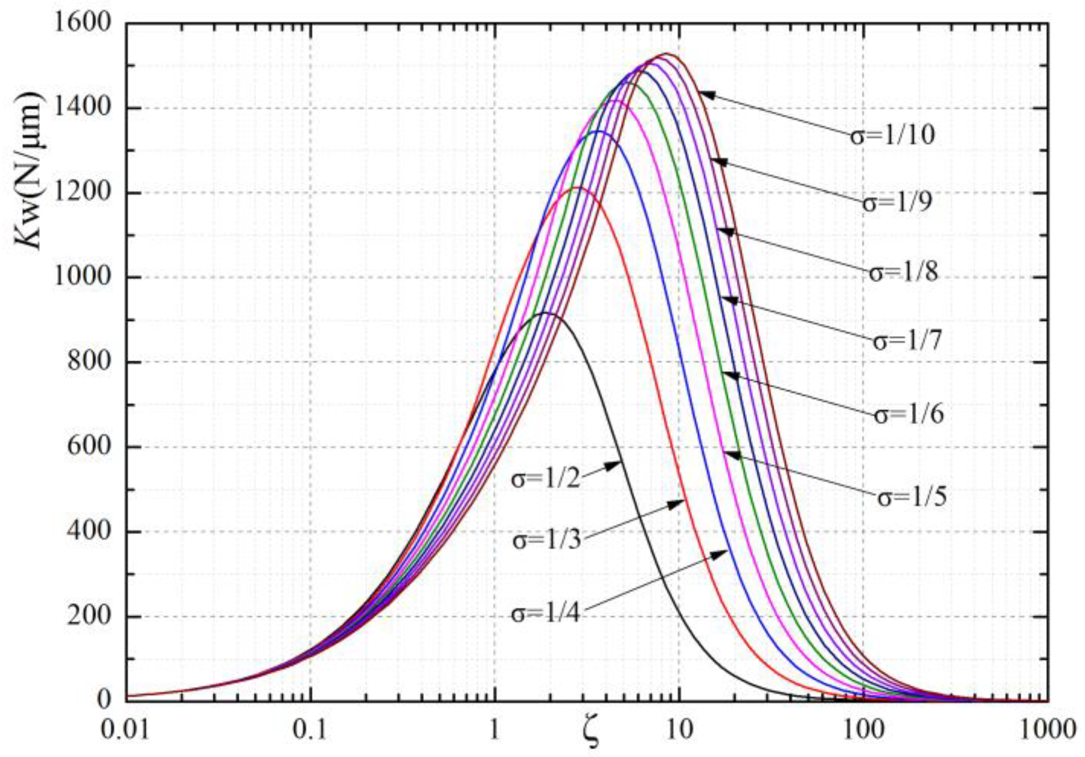
Next, W, Cw and Kw are calculated to optimize the bearing’s parameters P0, L, D, N and A0. Figure 3 also demonstrates that simplified calculation method is easier to operate compared with CFD and FEM.

4. Application Case Study

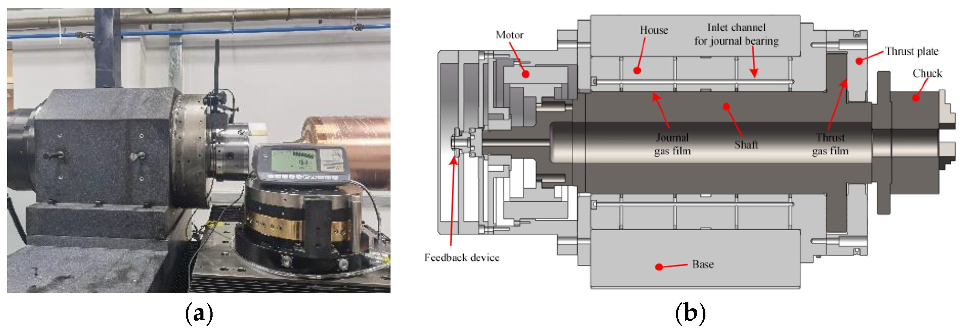
To validate and evaluate this method, the calculation data of the simplified calculation method were compared to those of CFD obtained from [29]. This aerostatic spindle, named C200, has been widely used in actual production. The picture of a C200 and its section view are shown in Figure 4. The C200 spindle is a heavy-duty bearing, which is designed to carry a load of more than 1000 kg under the condition of double-end support. Thus far, we have produced more than 16 spindles, which have proven to be a successful product. Its earliest engineering design adopts the method described in this paper. Structural and gas-supply parameters are shown in Table 1. The LCC of the calculation examples of different eccentricities are shown in Table 2.
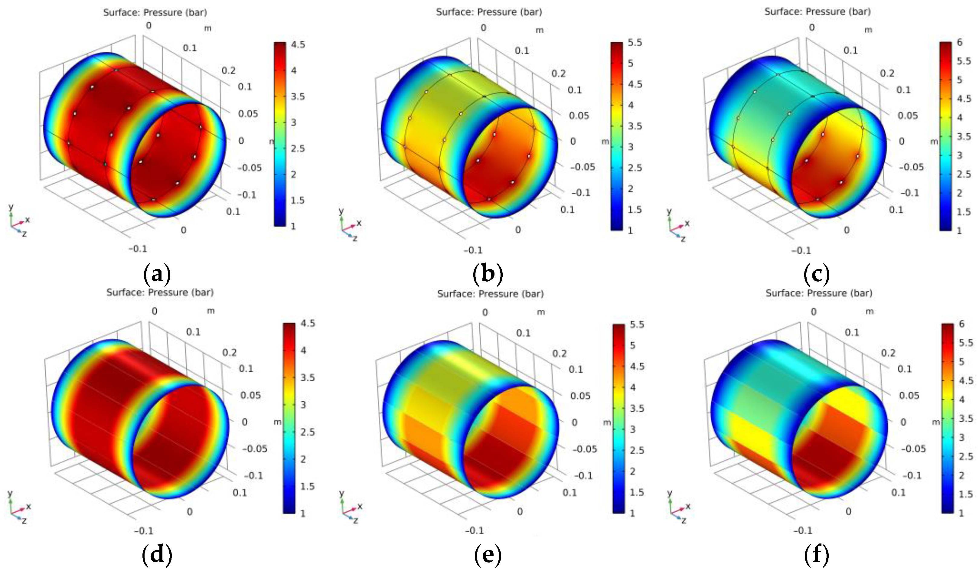
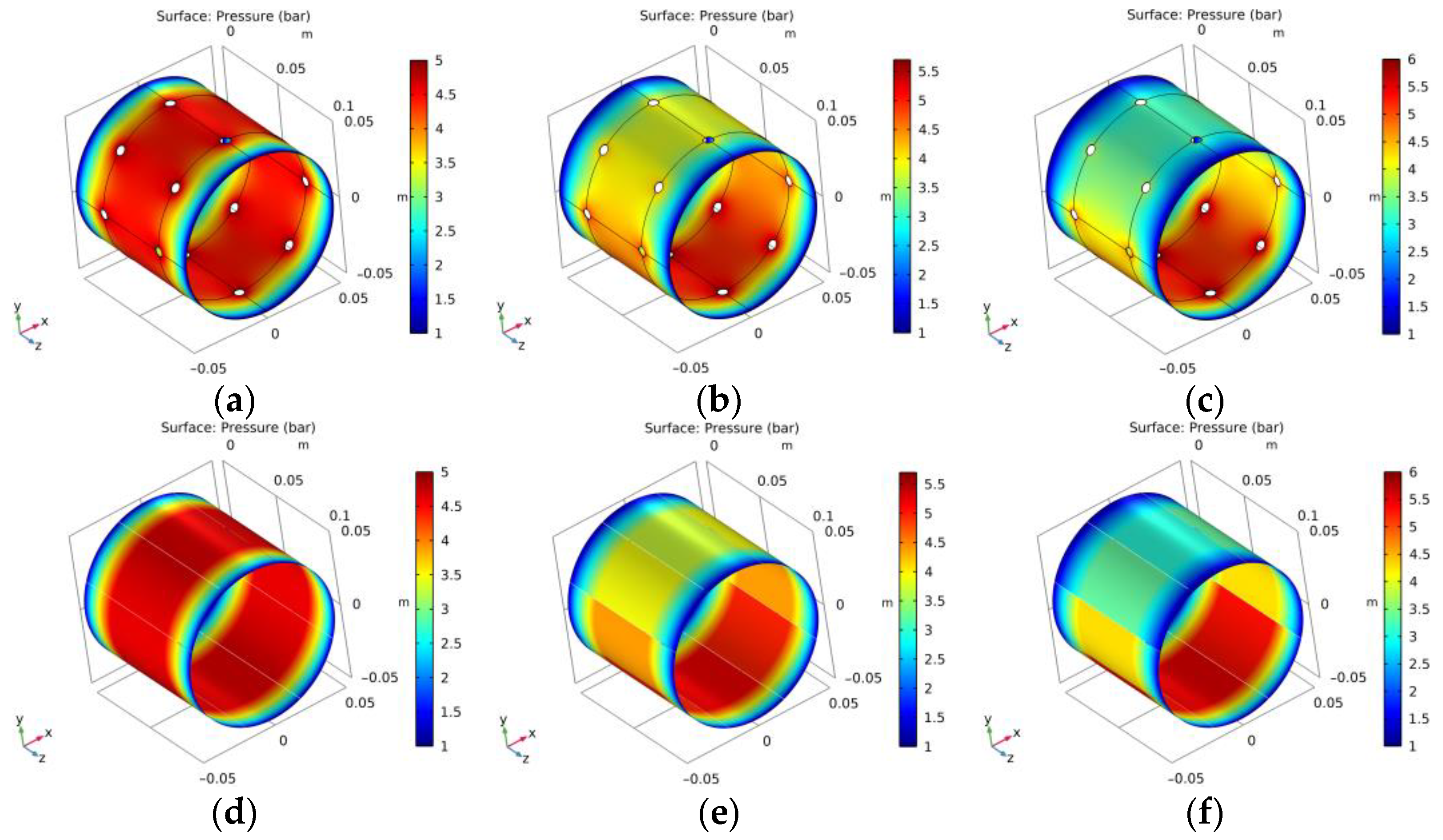
Figure 5 shows the calculation results of CFD and the simplified method described in this paper under different eccentricities, which are 0, 0.25, and 0.5, respectively. The comparison shows that there are two main differences: (1) The geometric size of orifice is not considered in the one-dimensional flow model, so there is no raised high-pressure area in the cross-section; that is, the one-dimensional flow model cannot represent the diffusion flow after the orifice. (2) Since the diffusion flow is not considered, the flow resistance in the one-dimensional flow model is smaller than that in the total model of CFD. The orifice and gas film are somehow analogous to two nonlinear electric resistors, and the recess pressure is similar to the electric voltage between those two resistors. According to the Kirchhoff circuit law, the pressure after the orifice is smaller when calculated using the simplified one-dimensional model. Although the annular flow makes the calculated value of the one-dimensional flow model larger, the smaller pressure after the orifice makes the calculated value smaller; the superposition of those two effects makes the difference between the calculated values not very large.
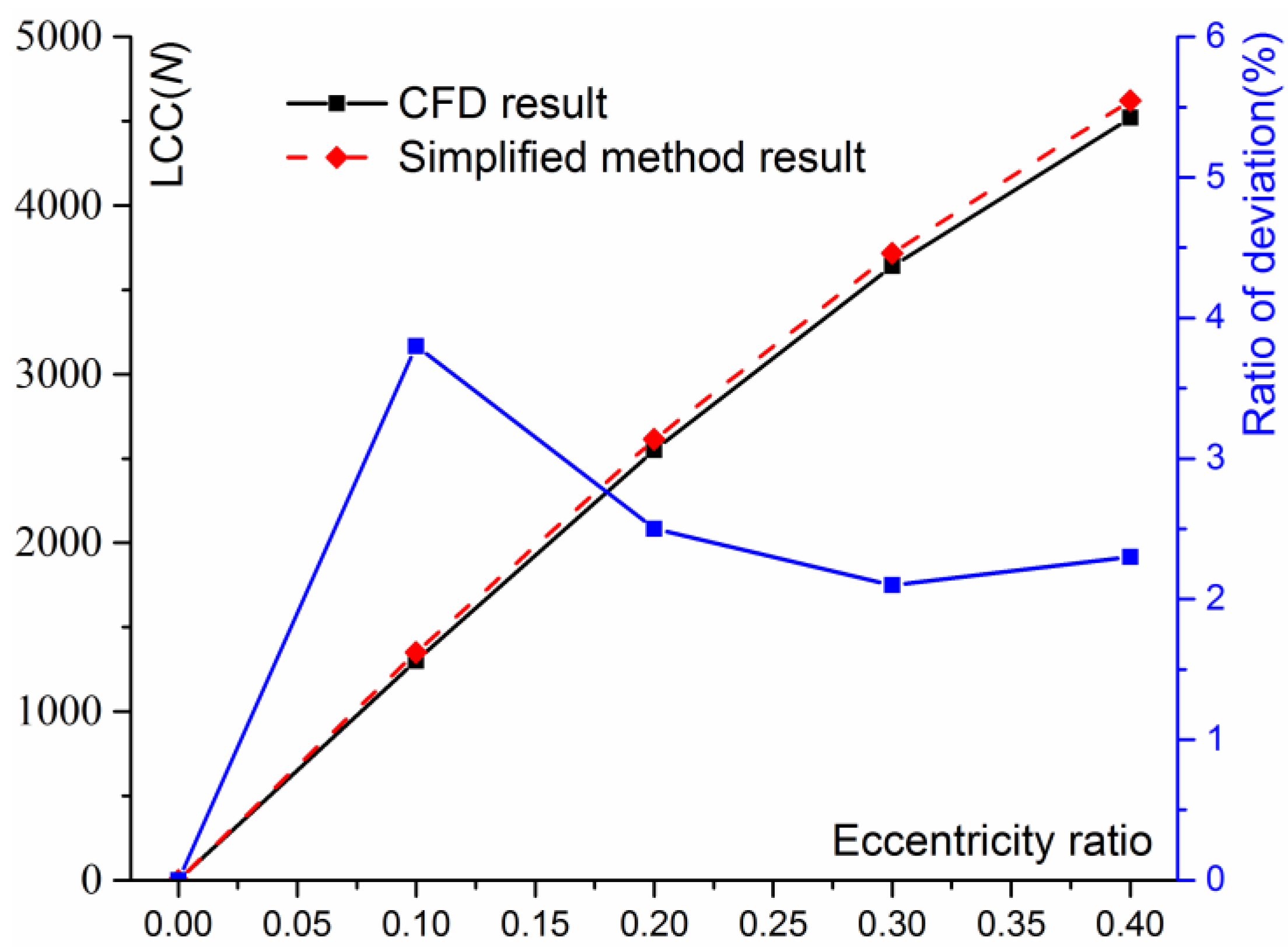
Table 2 shows that the calculation results of the simplified calculation method are in good agreement with those of CFD. In addition, those computational results are graphically compared in Figure 6. LCC calculated by this method is slightly larger than CFD, and the relative error is within 5% in all the different eccentricities. Obviously, the assumption of neglecting circumferential flow shows little effect in this case because gas film thickness is about 1/10,000 of spindle diameter. This simplified calculation method can be applied because most of the aerostatic bearings have a film thickness of about 5~15 μm and are small enough compared with the bearing structural parameters.
In the calculation process, the most notable is the time taken by CFD and the simplified calculation method. In order to obtain the calculation results in Figure 6, CFD calculation took about 26 min and the simplified calculation method took only a few seconds; both programs were run on the same computer with an i7 CPU, not to mention the half-day of pre-modeling with CFD. Considering the calculation accuracy and efficiency, the method proposed in this paper is a very effective method in the early stage of engineering design.
Figure 7 shows another widely used precision spindle in diamond-turning lathe, with a diameter of 100 mm, named C100, with their parameters listed in Table 3. Thus far, we have produced more than 50 spindles; in addition, its initial design was completed by the method proposed in this paper. The pressure-distribution cloud map calculated using CFD is similar to Figure 5c, shown in Figure 8.
It can be seen from Table 4 that for this spindle, the LCC difference between those two methods becomes larger, but still does not exceed 10%. The main reason for this difference is annular flow. When the radial bearing is eccentric, the gas will generate a flow from a high-pressure area with thin film to the low pressure area with thick film, resulting in a decrease in bearing capacity. The one-dimensional flow model introduced in this paper does not take into account the annular flow; therefore, it is expected that the simplified method will predict a higher LCC than the CFD method for the small diameter of the main shaft.
The C100 and C200 have the same ratio between the orifice-end face and the entire bearing length, but the difference between the calculation results of C100 and C200 and the numerical analysis is not the same; the key lies in the orifices’ number. The C100 has only eight restrictors on each circumference, the division of each area is rougher, and the diffusion effect and annular flow are more obvious, so the calculation results are quite different from CFD.

5. Impact of ζ i on a Bearing’s Performance

According to Equation (12), Pd determines the pressure distribution in the gas film P once the bearing’s parameters have been provided, while Pd is determined by   ζ i deduced from Equations (20)–(25). Furthermore, the effects of a bearing’s parameters on its performance is affected by changing   ζ i .
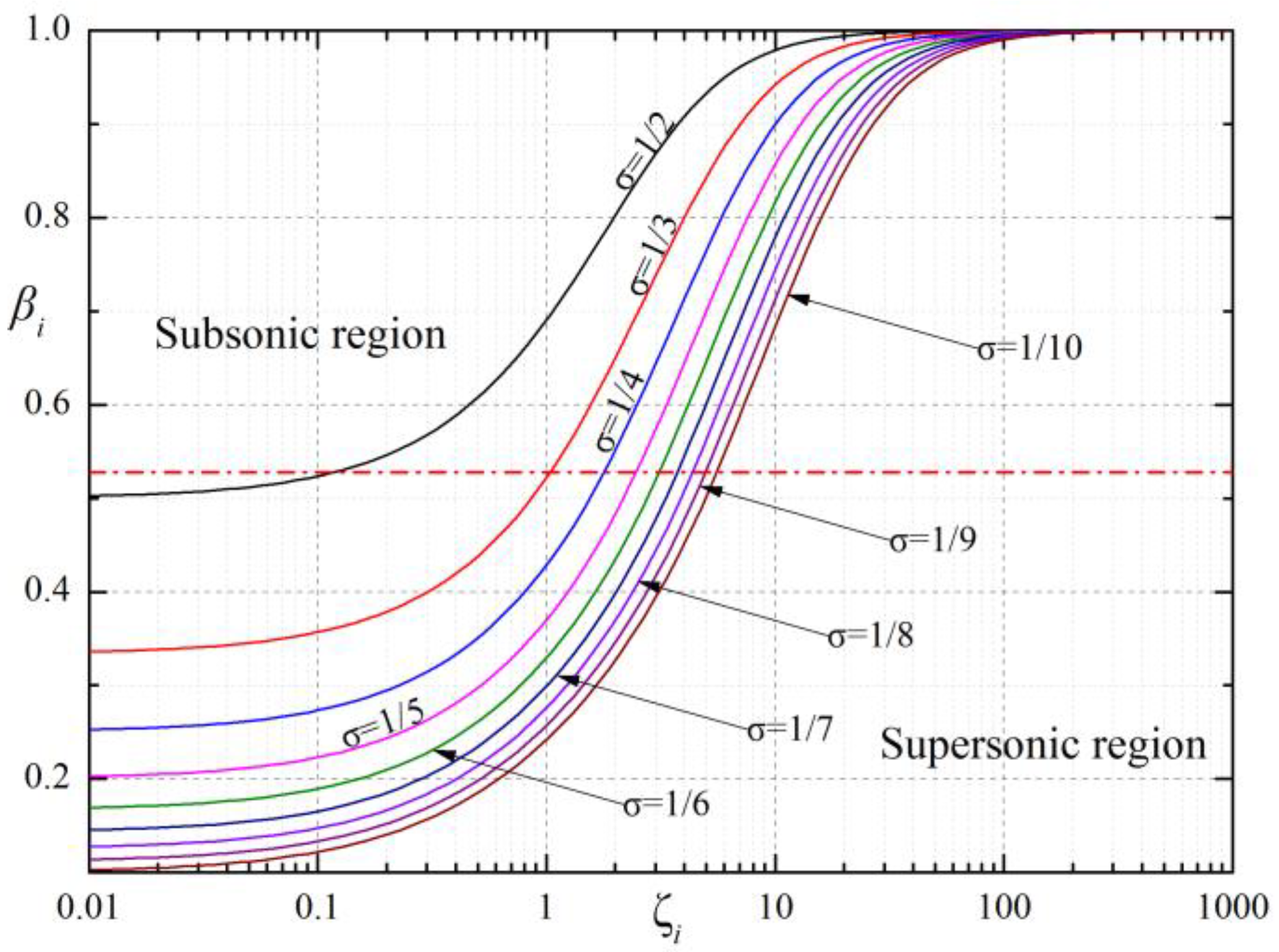
As demonstrated in Figure 9, the bearing’s performance can be determined by analyzing the impact of   ζ i   on β i according to Equation (21), β i = P di / P 0 and β i is determined by   ζ i . At varying supply pressures (from σ = 1/2 to σ = 1/10), β i increases with the growth in ζ i and tends to remain in the supersonic area when   ζ i   is larger than 10. Figure 9 also highlights that it is relatively easier for ζ i   to have an inclination to be saturated in the subsonic area with the decrease in supply pressure. Gas should flow sub-sonically in order to avoid shock waves; otherwise, LCC will sharply decrease and there is hardly any stiffness. From the red line of Figure 9, where β i = 0.528, it can be seen that the suitable range of the bearing’s parameters is narrow at extremely high supply pressure (σ < 1/8). Therefore, 0.4~0.6 MPa is an appropriate supply pressure in most cases.
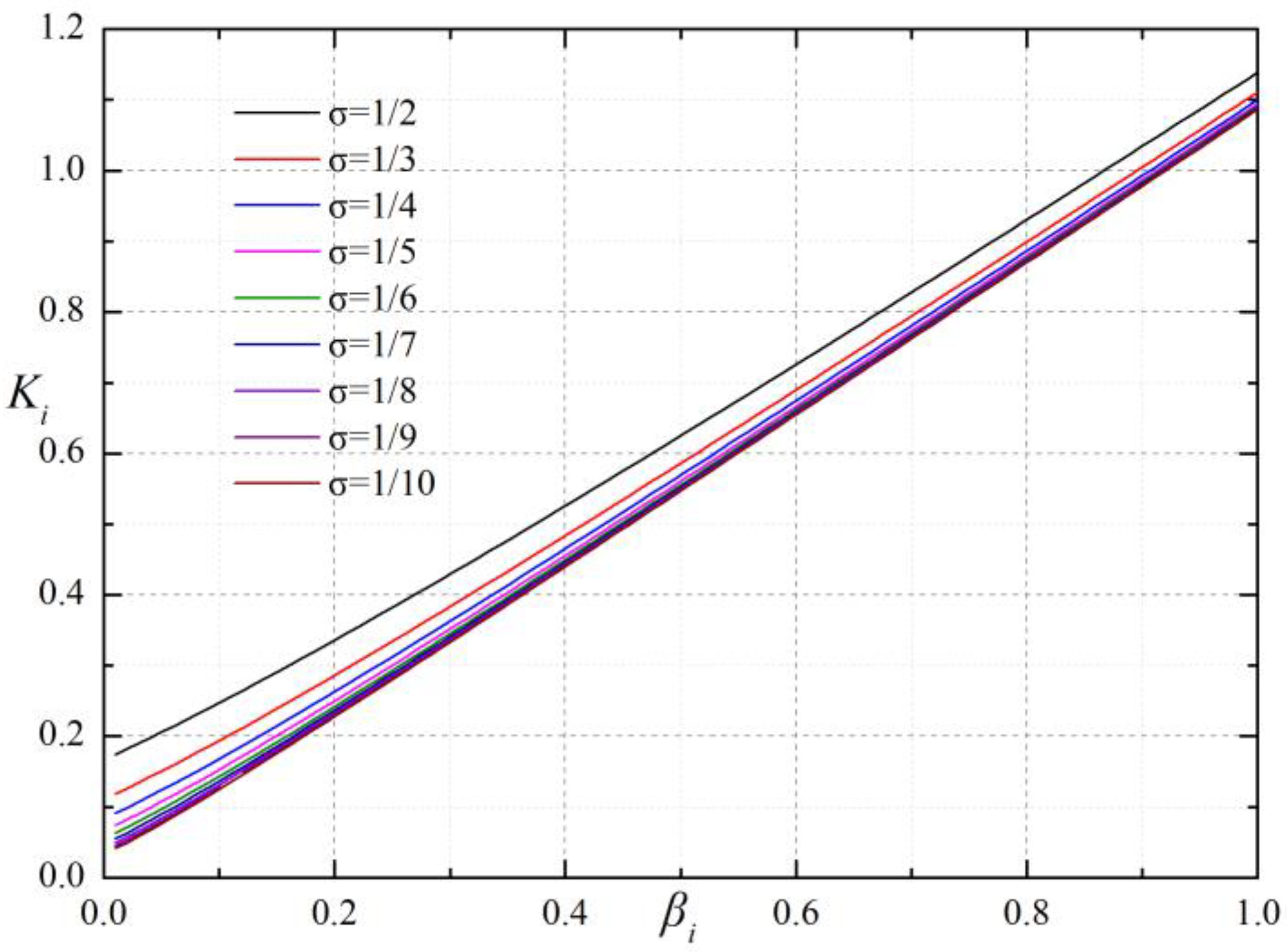
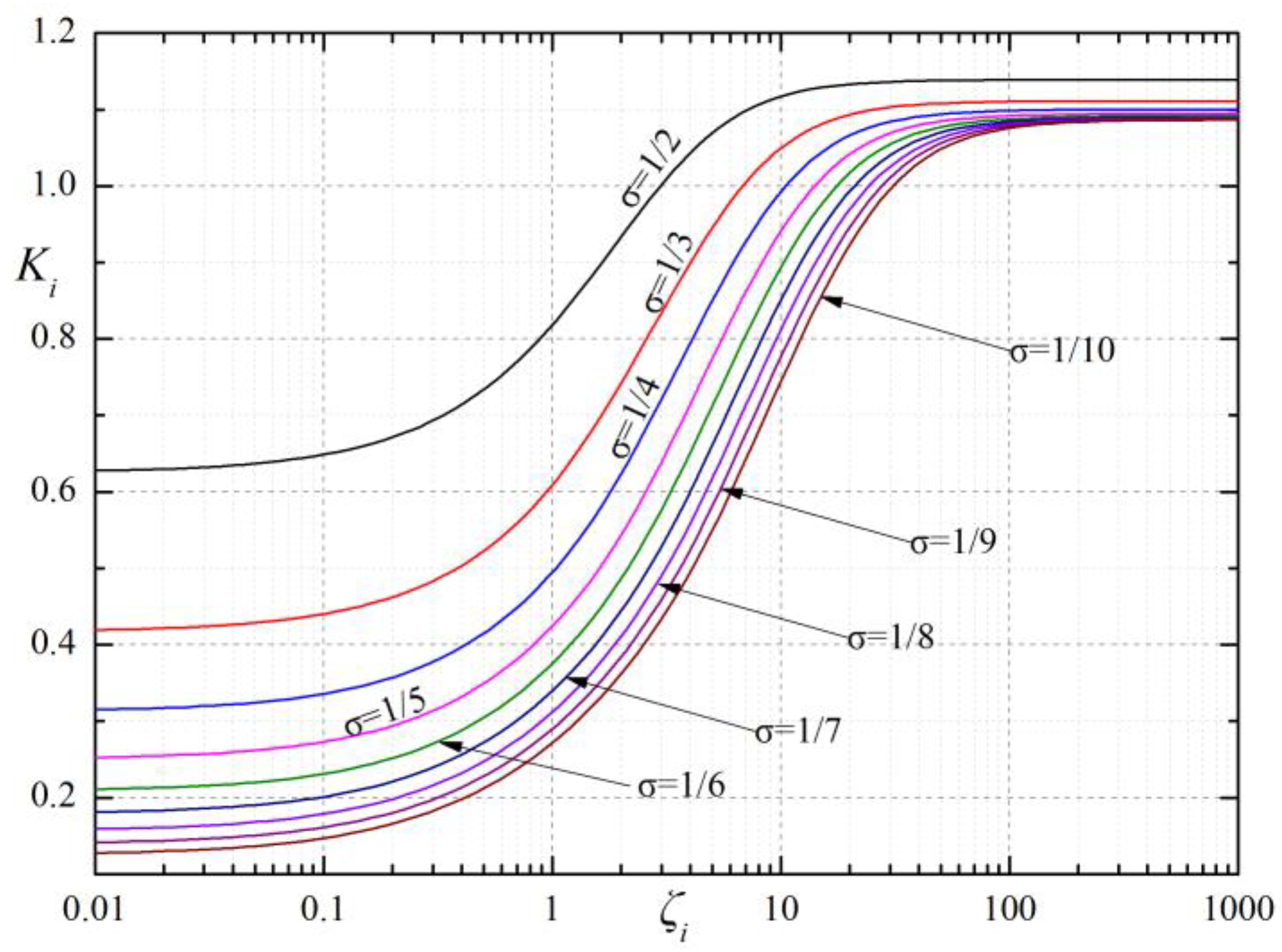
Generally, the ratio of l to L is equal to 1/4 or 1/5. When the ratio is 1/4, Figure 10 indicates the distribution of K i in Equation (17) with β i at different supply pressures. Obviously, K i is approximately linear to β i and almost independent of supply pressure. The distribution of   ζ i   with K i is shown in Figure 11. Thus, it is speculated that   ζ i   and K i have the same distribution to   ζ i   and β i . From the physical meaning of Equation (19), Ki is proportional to the LCC of the ith section.
Figure 12 demonstrates the influence of   ζ i on Kwi. Actually, the lines shown in Figure 12 are proportional to the derivative of lines shown in Figure 11. As Figure 12 indicates, the maximum stiffness exists when   ζ i   is 3~10 at different varying supply pressures. With increasing supply pressures, ζ i becomes larger after reaching the maximum stiffness. Compared with [8], this is the difference between a Cartesian coordinate system and cylindrical coordinate system.
The line shapes displayed in Figure 13 are the same as those in Figure 12, except that the value is several times larger. In other words, a bearings’ stiffness is directly connected with the stiffness in every section. It can be proved as follows:
The total stiffness Kw is the vector sum of Kwi in the vertical direction, that is
K w = i = 1 N K w i Δ h i Δ h cos θ i = i = 1 N K w i cos 2 θ i
The partial derivation of both sides of Equation (26) is expressed as Equation (27).
K w Δ h = i = 1 N K w i Δ h cos 2 θ i
To have the left side equal to zero, every partial derivative (i = 1~N) on the right side needs to be zero. To approach the maximal stiffness, every gas film section in the bearings must be designed for maximal stiffness.
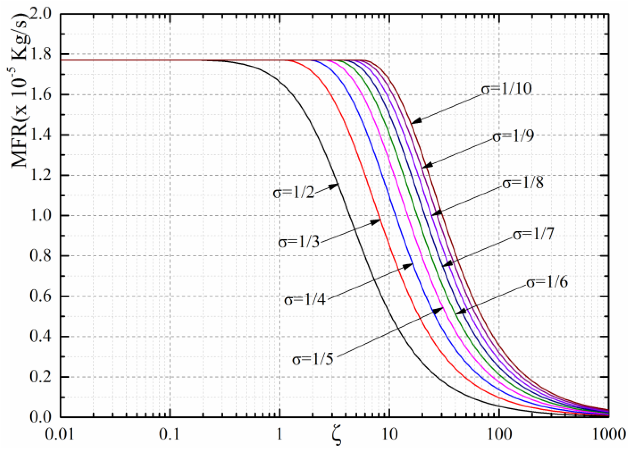
The effect of ζ i on MFR is shown in Figure 14. It is obvious that supply pressure has a significant influence on a bearings’ MFR. A bearings’ MFR will rise in pace with supply pressure. In addition, MFR tends to have a constant value when ζ i is smaller than 1. With the increase in ζ i , MFR can decrease due to the flow-rate characteristics of an ideal orifice.

6. Conclusions

In this study, a simplified calculation method of aerostatic journal bearing with MPOTRs was presented. The calculation procedure was summarized and can be programmed easily to analyze the performance of two-row-orifice type journal aerostatic bearings, which simplifies the analysis process of aerostatic journal bearing’s performance prediction and offers a straightforward way to optimize parameters. In addition, this method was verified with computational fluid dynamics by two actual case studies, and it was found that the LCC difference between those two methods is less than 5% for a 200 mm-diameter spindle, and less than 10% for a 100 mm-diameter spindle.
In order to satisfy the critical need for high stiffness and load carrying capacity, every gas film section in bearings should be designed to reach its maximal stiffness. From the calculation process, it was found that ζ i is a critical factor that influences bearings’ performance through the equations derived from this method. The following conclusions can be reached by analyzing the association between ζ i   and performance parameters:
(1)
ζ i   is a crucial parameter of the bearing’s performance. It can be assessed by the discharge correction factor , sectional area of the orifice A0, orifice number N, gas film thickness in the ith section hi, kinematic viscosity of air η, atmospheric density ρa, atmospheric pressure Pa, journal bearing diameter D, distance between orifices and gas film edge l, and journal bearing length L.
(2)
ζ i is the product of f1 (a gas-channel coefficient), f2 (a gas-lubricant coefficient) and f3 (a bearing structural coefficient). A bearing with better performance, such as LCC, stiffness and MFR, could be obtained if   ζ i is in the range of 1~10.
(3)
With increasing   ζ i , a bearing’s stiffness in each section will reach a maximal value and then decrease. Here, 0.4~0.6 MPa is an appropriate supply pressure range in most cases, as the bearing’s parameters are narrow at extremely high supply pressures to avoid shock waves.

Author Contributions

Conceptualization, Y.W., J.X. and B.W.; Methodology, Y.W. and Z.Q.; Software, Y.W. and J.X.; Validation, Y.W.; Formal Analysis, W.C.; Investigation, Y.W. and J.X.; Resources, Y.W. and B.W.; Data curation, Y.W. and J.X.; Writing—original draft preparation, J.X.; Writing—review and editing, Y.W. and W.C.; Visualization, Y.W. and J.X.; Supervision, Z.Q. and B.W.; Project administration, Z.Q. and B.W.; Funding acquisition, Z.Q. and B.W. All authors have read and agreed to the published version of the manuscript.

Funding

The work was supported by the Open Project Program of State Key Laboratory of applied optics (SKLAO2021001A05); National Natural Science Foundation of China (No.51905130); and Heilongjiang Provincial Natural Science Foundation of China (No. LH2020E039).

Data Availability Statement

The data supporting reported results by the authors can be sent by e-mail.

Conflicts of Interest

The authors declare no conflict of interest.

Nomenclature

βi Pressure   ratio   in   i th   sec tion ,   P d i / P 0
βαCritical pressure ratio
ηKinematic viscosity of air
ρDensity of gas in the bearing
ρaAtmospheric density
σ Ratio   of   pressure ,   P a / P 0
εEccentricity ratio
Discharge correction factor
φ Discharge coefficient
ζ i Product of three coefficients
A0Sectional area of the orifice
bWidth of 1-D gas film
CFDComputational fluid dynamics
d0Diameter of the orifice
DJournal bearing diameter
f1iGas channel coefficient
f2Lubricant physical coefficient
f3Bearing structural coefficient
FEMFinite element method
h0Designed gas film thickness
hiGas film thickness in ith section
ΔhFilm thickness changing value
kGas specific heat ratio
KwBearing stiffness
lDistance between orifices and gas film edge
LJournal bearing length
LCC, WLoad carrying capacity
LCCE, CwLCC coefficient
MFRMass flow rate
MPOTRsMultiple pocketed orifice-type restrictors
m ˙ Mass flow rate through the orifice
M ˙ Bearing mass flow rate
NOrifice number
PPressure in the bearing
PaAtmospheric pressure
PdPressure at orifice outlet
P0Supply pressure

References

  1. Shinno, H.; Yoshioka, H.; Taniguchi, K. A Newly Developed Linear Motor-Driven Aerostatic X-Y Planar Motion Table System for Nano-Machining. CIRP Ann. Manuf. Technol. 2007, 56, 369–372. [Google Scholar] [CrossRef]
  2. Chen, G.; Ju, B.; Fang, H.; Chen, Y.; Yu, N.; Wan, Y. Air bearing: Academic insights and trend analysis. Int. J. Adv. Manuf. Technol. 2019, 106, 1191–1202. [Google Scholar] [CrossRef]
  3. Ding, J.; Chang, Y.; Chen, P.; Zhuang, H.; Ding, Y.; Lu, H.; Chen, Y. Dynamic modeling of ultra-precision fly cutting machine tool and the effect of ambient vibration on its tool tip response. Int. J. Extrem. Manuf. 2020, 2, 025301. [Google Scholar] [CrossRef]
  4. Raniachandra, S. A solution of Reynolds equation for a full finite journal bearing. J. Fluids Eng. 1961, 83, 589–593. [Google Scholar]
  5. Pandian, M.C. A new method for the numerical solution of the Reynolds equation for gas-lubricated slider bearings. J. Eng. Math. 1985, 19, 3–19. [Google Scholar] [CrossRef]
  6. Anaya-Dufresne, M.; Sinclair, G.B. Some Exact Solutions of Reynolds Equation. J. Tribol. 1995, 117, 560–562. [Google Scholar] [CrossRef]
  7. Powell, J.W. The Design of Aerostatic Bearings; The Machinery Publishing Co., Ltd.: London, UK, 1970; pp. 68–112. [Google Scholar]
  8. Li, Y.; Ding, H. A simplified calculation method on the performance analysis of aerostatic thrust bearing with multiple pocketed orifice-type restrictors. Tribol. Int. 2012, 56, 66–71. [Google Scholar] [CrossRef]
  9. Tang, I.C.; Gross, W.A. Analysis and Design of Externally Pressurized Gas Bearings. Tribol. Trans. 1962, 5, 261–284. [Google Scholar] [CrossRef]
  10. Jason, R.L. Analytical and Experimental Study of Externally Pressurized Air Lubricated Journal Bearings. J. Basic Eng. 1962, 84, 159–165. [Google Scholar]
  11. Colombo, F.; Raparelli, T.; Trivella, A.; Viktorov, V. Lumped parameters models of rectangular pneumatic pads: Static analysis. Precis. Eng. 2015, 42, 283–293. [Google Scholar] [CrossRef] [Green Version]
  12. Mori, H.; Yabe, H. Analysis of Externally Pressurized Circular Thrust Gas-Bearing with Multiple Supply Holes. Tribol. Trans. 1964, 7, 269–276. [Google Scholar] [CrossRef]
  13. Mori, H.; Yabe, H.; Ohnishi, K. Analysis of Externally Pressurized Rectangular Pads with Multiple Supply Holes. Tribol. Trans. 1966, 9, 391–401. [Google Scholar] [CrossRef]
  14. Reddi, M.M. Finite-Element Solution of the Incompressible Lubrication Problem. J. Lubr. Technol. 1969, 91, 524–533. [Google Scholar] [CrossRef]
  15. Reddi, M.M.; Chu, T.Y. Finite Element Solution of the Steady-State Compressible Lubrication Problem. J. Lubr. Technol. 1970, 92, 495–502. [Google Scholar] [CrossRef]
  16. Wadhwa, S.; Sinhasan, R.; Singh, D. Analysis of externally pressurized gas bearings by an incremental finite element method. Wear 1981, 69, 133–141. [Google Scholar] [CrossRef]
  17. Nguyen, S.H. p-Version Finite Element Analysis of Gas Bearings of Finite Width. J. Tribol. 1991, 113, 417–420. [Google Scholar] [CrossRef]
  18. Lo, C.-Y.; Wang, C.-C.; Lee, Y.-H. Performance analysis of high-speed spindle aerostatic bearings. Tribol. Int. 2005, 38, 5–14. [Google Scholar] [CrossRef]
  19. Wang, N.; Chang, C. An Application of Newton’s Method to the Lubrication Analysis of Air-Lubricated Bearings. Tribol. Trans. 1999, 42, 419–424. [Google Scholar] [CrossRef]
  20. Wadhwa, S.; Sinhasan, R.; Singh, D. Analysis of orifice compensated externally pressurized gas bearings. Tribol. Int. 1983, 16, 203–211. [Google Scholar] [CrossRef]
  21. Cui, H.; Gong, W.; Zheng, Y.; Li, Y.; Wang, W.; Jiang, Z. A simplified FEM analysis on the static performance of aerostatic journal bearings with orifice restrictor. Proc. Inst. Mech. Eng. Part J J. Eng. Tribol. 2020, 235, 1379–1389. [Google Scholar] [CrossRef]
  22. Li, Y.T.; Ding, H. Design analysis and experimental study of aerostatic linear guideways used in a high acceleration and high precision xy stage. Proc. Inst. Mech. Eng. Part J J. Eng. Tribol. 2007, 221, 1–9. [Google Scholar] [CrossRef]
  23. Charki, A.; Bigaud, D.; Guérin, F. Behavior analysis of machines and system air hemispherical spindles using finite element modeling. Ind. Lubr. Tribol. 2013, 65, 272–283. [Google Scholar] [CrossRef]
  24. Cui, H.; Xia, H.; Lei, D.; Zhang, X.; Jiang, Z. A Calculation Method to Investigate the Effects of Geometric Parameters and Operational Conditions on the Static Characteristics of Aerostatic Spherical Bearings. J. Tribol. 2018, 141, 021101. [Google Scholar] [CrossRef]
  25. Wu, Y.; Qiao, Z.; Xue, J.; Wang, B.; Chen, W. A newly treated boundary conditions to enhance accuracy of finite element analysis for orifice-type aerostatic bearings. Adv. Eng. Softw. 2022, 173, 103277. [Google Scholar] [CrossRef]
  26. Chen, G.; Ge, Y.; Lu, Q.; Zhang, W.; Wang, S. Air film pressure field characteristics of aerostatic thrust bearing with orifice blockage. Int. J. Adv. Manuf. Technol. 2022. [Google Scholar] [CrossRef]
  27. Rajdeep, D.; Andreas, H.; Dirk, W.; Patrick, J.; Beat, H.M. Numerical modeling and design decisions for aerostatic bearings with relatively large nozzle sizes in Magic-Angle Spinning (MAS) systems. Tribol. Int. 2022, 175, 107855. [Google Scholar]
  28. Cui, H.-L.; Wang, Y.; Wang, B.-R.; Yang, H.; Xia, H. Numerical Simulation and Experimental Verification of the Stiffness and Stability of Thrust Pad Aerostatic Bearings. Chin. J. Mech. Eng. 2018, 31, 23. [Google Scholar] [CrossRef] [Green Version]
  29. Wu, D.; Wang, B.; Luo, X.; Qiao, Z. Design and analysis of aerostatic spindle with high load characteristics for large ultra-precision drum lathe. Proc. Inst. Mech. Eng. Part J J. Eng. Tribol. 2015, 229, 1425–1434. [Google Scholar] [CrossRef] [Green Version]
  30. Belforte, G.; Raparelli, T.; Viktorov, V.; Trivella, A. Discharge coefficients of orifice-type restrictor for aerostatic bearings. Tribol. Int. 2007, 40, 512–521. [Google Scholar] [CrossRef]
  31. Belforte, G.; Colombo, F.; Raparelli, T.; Trivella, A.; Viktorov, V. A new identification method of the supply hole discharge coefficient of gas bearings. Tribol. Des. WIT Trans. Eng. Sci. 2010, 66, 95–105. [Google Scholar] [CrossRef] [Green Version]
  32. Belforte, G.; Raparelli, T.; Trivella, A.; Viktorov, V. Identification of Discharge Coefficients of Orifice-Type Restrictors for Aerostatic Bearings and Application Examples. New Tribol. Ways 2011, 359–380. [Google Scholar] [CrossRef] [Green Version]
  33. Belforte, G.; Raparelli, T.; Trivella, A.; Viktorov, V.; Visconte, C. CFD Analysis of a Simple Orifice-Type Feeding System for Aerostatic Bearings. Tribol. Lett. 2015, 58, 25. [Google Scholar] [CrossRef] [Green Version]
  34. Renn, J.-C.; Hsiao, C.-H. Experimental and CFD study on the mass flow-rate characteristic of gas through orifice-type restrictor in aerostatic bearings. Tribol. Int. 2004, 37, 309–315. [Google Scholar] [CrossRef]
  35. Yoshimoto, S.; Yamamoto, M.; Toda, K. Numerical Calculations of Pressure Distribution in the Bearing Clearance of Circular Aerostatic Thrust Bearings With a Single Air Supply Inlet. J. Tribol. 2006, 129, 384–390. [Google Scholar] [CrossRef]
  36. Eleshaky, M.E. CFD investigation of pressure depressions in aerostatic circular thrust bearings. Tribol. Int. 2009, 42, 1108–1117. [Google Scholar] [CrossRef]
  37. Chang, S.; Chan, C.; Jeng, Y. Numerical analysis of discharge coefficients in aerostatic bearings with orifice-type restrictors. Tribol. Int. 2015, 90, 157–163. [Google Scholar] [CrossRef]
  38. Ting, G.-C.; Lee, Y.-H.; Huang, K.-Y. Development and experimental verification of radial-axial integrated cup-shaped aerostatic bearing for miniature turbine of dental handpiece. Tribol. Int. 2022, 174, 107740. [Google Scholar] [CrossRef]
  39. Li, W.; Wang, G.; Feng, K.; Zhang, Y.; Wang, P. CFD-based investigation and experimental study on the performances of novel back-flow channel aerostatic bearings. Tribol. Int. 2021, 165, 107319. [Google Scholar] [CrossRef]
  40. Neves, M.; Schwarz, V.; Menon, G. Discharge coefficient influence on the performance of aerostatic journal bearings. Tribol. Int. 2010, 43, 746–751. [Google Scholar] [CrossRef]
  41. Zhou, Y.; Chen, X.; Chen, H. A hybrid approach to the numerical solution of air flow field in aerostatic thrust bearings. Tribol. Int. 2016, 102, 444–453. [Google Scholar] [CrossRef]
  42. Song, L.; Cheng, K.; Ding, H.; Chen, S. Analysis on discharge coefficients in FEM modeling of hybrid air journal bearings and experimental validation. Tribol. Int. 2018, 119, 549–558. [Google Scholar] [CrossRef]
  43. Miyatake, M.; Yoshimoto, S. Numerical investigation of static and dynamic characteristics of aerostatic thrust bearings with small feed holes. Tribol. Int. 2010, 43, 1353–1359. [Google Scholar] [CrossRef]
  44. Gero, L.R.; Ettles, C.M.M. An Evaluation of Finite Difference and Finite Element Methods for the Solution of the Reynolds Equation. ASLE Trans. 1986, 29, 166–172. [Google Scholar] [CrossRef]
  45. Belforte, G.; Colombo, F.; Raparelli, T.; Trivella, A.; Viktorov, V. Performance of Externally Pressurized Grooved Thrust Bearings. Tribol. Lett. 2009, 37, 553–562. [Google Scholar] [CrossRef]
  46. Gao, S.; Cheng, K.; Chen, S.; Ding, H.; Fu, H. CFD based investigation on influence of orifice chamber shapes for the design of aerostatic thrust bearings at ultra-high speed spindles. Tribol. Int. 2015, 92, 211–221. [Google Scholar] [CrossRef]
Figure 1. Configuration of a journal bearing with MPOTRs.
Lubricants 10 00332 g001
Figure 2. Flow model in each part of ith section.
Lubricants 10 00332 g002
Figure 3. Calculation procedures of the simplified calculation method.
Lubricants 10 00332 g003
Figure 4. The aerostatic spindle and its cross-section view: (a) picture of the C200 spindle, (b) cross-section view and diagram of the C200 spindle.
Lubricants 10 00332 g004
Figure 5. The aerostatic C200 spindle and air-pressure-distribution simulation results calculated using CFD and simplified method: (a) the CFD result without eccentricity, (b) the CFD result with eccentricity ratio of 0.25, (c) the CFD result with eccentricity ratio of 0.5, (d) the simplified method result without eccentricity, (e) the simplified method result with eccentricity ratio of 0.25, (f) the simplified method result with eccentricity ratio of 0.5.
Lubricants 10 00332 g005
Figure 6. LCC calculated by CFD and simplified calculation method.
Lubricants 10 00332 g006
Figure 7. The aerostatic spindle used in diamond-turning lathes: (a) picture of spindle, (b) cross-section view and diagram of the C100 spindle.
Lubricants 10 00332 g007
Figure 8. The aerostatic C100 spindle and air-pressure-distribution simulation results calculated using CFD and simplified method: (a) the CFD result without eccentricity, (b) the CFD result with eccentricity ratio of 0.25, (c) the CFD result with eccentricity ratio of 0.5, (d) the simplified method result without eccentricity, (e) the simplified method result with eccentricity ratio of 0.25, (f) the simplified method result with eccentricity ratio of 0.5.
Lubricants 10 00332 g008
Figure 9. Effect of ζ i on β i .
Lubricants 10 00332 g009
Figure 10. Effect of β i on K i .
Lubricants 10 00332 g010
Figure 11. Effect of ζ i on K i .
Lubricants 10 00332 g011
Figure 12. Effect of ζ i on Kwi.
Lubricants 10 00332 g012
Figure 13. Effect of ζ i on Kw.
Lubricants 10 00332 g013
Figure 14. Effect of ζ on MFR.
Lubricants 10 00332 g014
Table 1. Parameters of the aerostatic journal bearing (C200).
TermSpecification
Length ,   L 225 mm
Diameter of spindle rotor, D200 mm
Orifice-end distance, l65 mm
Orifice diameter, d00.2 mm
Gas film thickness, h020 μm
Supply   pressure ,   P 0 0.5 MPa
Number of orifices in each row, N12
LubricantClean air
Table 2. LCC of the calculation example of different eccentricities (C200).
Eccentricity RatioEccentricity ValueCFD ResultSimplified Method ResultRatio of Deviation
00 μm000
0.12 μm1300 N1350 N3.8%
0.24 μm2550 N2614 N2.5%
0.36 μm3640 N3717 N2.1%
0.48 μm4520 N4622 N2.3%
Table 3. Parameters of the aerostatic journal bearing (C100).
TermSpecification
Length ,   L 100 mm
Diameter of spindle rotor, D100 mm
Orifice-end distance, l25 mm
Orifice diameter, d00.2 mm
Gas film thickness, h015 μm
Supply   pressure ,   P 0 0.5 MPa
Number of orifices in each row, N8
LubricantClean air
Table 4. LCC of the calculation example of different eccentricity (C100).
Eccentricity ValueCFD ResultSimplified Method ResultRatio of Deviation
0 μm0 N0 N0
1.2 μm242.8 N266.2 N9.6%
2.4 μm476.3 N514.3 N8.0%
3.6 μm673.5 N730.6 N8.5%
4.8 μm838.7 N912.2 N8.7%
6.0 968.8 N1061 N9.5%
Publisher’s Note: MDPI stays neutral with regard to jurisdictional claims in published maps and institutional affiliations.