1. Introduction
Elastomeric materials are used in many applications, such as the automobile industry, sealants, abrasive tools, and agricultural equipment. In many applications, the wear study of elastomers in different operating conditions is essential in product selection and prediction of product life. However, estimating elastomeric wear is challenging as the wear mechanism changes with different material properties and operating conditions. The wear of elastomers is generally affected by variables such as normal load, sliding distance, sliding velocity, rotational speed, temperature, running duration, surface properties of the counter surface, and abrasives [
1,
2]. Moreover, the material properties also play an important role in wear rate. Modeling of wear for elastomers is limited as compared to metals and their alloys. In general, experimental data obtained for elastomers is fitted into empirical equations for the wear modeling in most of the studies. Contradicting results are presented by Lancaster [
3] and Rhee [
4], where both linear and non-linear relations between wear volume and operating variables are established. Moreover, Viswanath and Bellow [
5] considered the roughness of the counter surface as an additional parameter to develop a relation between wear rate and input variables. Panda et al. [
6] proposed a model for the wear of polymers considering the topography of the counter surface. Different wear mechanisms exist when an elastomer rolls and slides against a relatively more rigid surface. These wear mechanisms are Schallamach waves, abrasion, fatigue, adhesion, and roll formation [
1,
7,
8]. The descriptions of these wear mechanisms are listed in
Table 1.
Polyurethane is one of the most used materials for polishing pads and tools used in the finishing process because of its superior mechanical, physical, thermal, and chemical stability. In optics and related fields, polyurethane pads with porous structures are widely used for various polishing purposes [
9]. The elastic behavior of the polyurethane-based tools is affected by the working environment, i.e., temperature, loading frequency, and wetting conditions [
10]. The elastic modulus and hardness of polyurethane are related to each other. The hardness of polyurethane tools can be influenced by several factors, including tool wear, the inclusion of debris, and loose abrasive particles, which further impact the quality of the finished surface. The finishing of gears, optical materials, bearings, and medical implants is carried out using elastic grinding wheels. The major disadvantage of using these elastic grinding wheels is that the material used for tool fabrication are thermoset, and it is chemically cross-linked, which limits the remolding of the wheels [
11]. The commercially used flexible tools are fabricated by Tyrolit Group, Abtex LLC, and Misumi Corporation. These commercially available tools are mainly used as a substitute for rigid grinding tools and are commonly used for deburring, scratch removal, and fine grinding. The finishing of different components to a nanometer level using these commercially available tools is rarely addressed. The tool developed in this work can finish different components to a nanolevel finish at a good finishing rate.
Flexible abrasive tool finishing (FATF), also known as bonded abrasive tool finishing, is a technique used for finishing a wide variety of materials, particularly optical components. There are different issues associated with the finishing techniques used in the previous works. The most common problems are low finishing rates, environmental issues, excessive tool loading, and higher tooling costs. These problems can be overcome with the help of the fabricated tool in this work. This tool has a self-replenishing ability and is also flexible, which helps with uniform finishing. There is no environmental concern while using this tool. The fabrication technique is cost-effective. However, tool loading is a concern for the developed tool. Therefore, the performance of this tool is analyzed to correlate the loading and tool wear with the operating conditions. These tools have embedded abrasive particles that can conform to the shape of the workpiece surface. The porous open-cell structure allows for the retention of lubricants during the finishing experiments. The properties of flexible tools, such as their porosity, hardness, and elastic modulus, are related to their finishing ability. In the grinding and fine-finishing of components, tool wear and tool loading affect the tool performance and thus reduce the overall efficiency of the process. The quality of the finished surface depends on the wear and loading of the flexible abrasive tool. The wear of the flexible tools is related to their characteristics and the process parameters used in the finishing process. It is reported that polyethylene wear increases with the roughness of the counter surface [
12]. The adhesive wear mechanism is observed when sliding polyketone and polytetrafluoroethylene against different counter surfaces [
13]. An increase in the roughness of the counter surface leads to a lower coefficient of friction for polymer composites and elastomers [
14,
15].
In the present work, the effect of surface properties of different counter surfaces on the wear of the fabricated tools and the loading of these tools is studied. The effect of morphology and wear of polyurethane-based flexible abrasive tools having porous structures on the mechanism of material removal is also discussed. After finishing, the morphological study and weight loss analysis of the used flexible tools are carried out. It is observed that these tools are less resistant to wear, but as the process progresses, the wear of the tools reduces. However, various modifications to the tool microstructure and composition have been observed. The inclusion of chips in the microstructure of the tools, which alters their characteristics, is the most apparent change observed after the finishing operation. As the tool material is very soft and has pores, chips find difficulty escaping from the finishing zone as these chips are likely to get stuck in the tool material. During the finishing, some of the chips may be thrown away due to centrifugal force, but new chips get removed from the workpiece and stick to the tool. So, it is a reoccurring process. These chips are not participating in the material removal but abrade the surface depending on the rotational speed of the tool. The loose particles are abrasives that have fallen out of the polymer matrix. These abrasive particles are not completely removed from the finishing zone as some of them escaped from the finishing zone, and a few more will be separated from the tool during the finishing action. The self-replenishing property of the tool helps introduce new abrasives to facilitate finishing operations.
3. Results and Discussion
3.1. Microstructure of the Fabricated Tool
A small portion of the fabricated flexible abrasive tool is analyzed in SEM, as shown in
Figure 4. The foamed structure bonds abrasive particles, and the pores in fabricated tools are open and interconnected. Open pores help in fluid absorption, retain lubricants and release them when pressed on the workpiece. This can be termed a self-lubricating property [
18], and it is very useful in the finishing process. The abrasive embedment can be proven with the cross-section SEM image of the flexible tool. It can be seen that the abrasive particles are there in the cut part, which suggests that the abrasive particles are properly embedded in the foamed structure. As these tools can easily absorb the DI water, it can be concluded that the pores are open and interconnected. The solvent casting method allows for creating voids in the foamed structure, which results in interconnected pores. These open-cell foams can absorb and retain more fluid as compared to closed-cell foams.
Energy dispersive X-ray spectroscopy (EDS) is used for element mapping of the new flexible abrasive tool, as shown in
Figure 5. The elemental mapping confirms the distribution and existence of abrasive particles within the foamed structure.
3.2. Elastic Property of the Fabricated Tool
Dynamic Mechanical Analysis (DMA) is carried out in compression mode to measure the elastic properties of the tools. The storage modulus, loss modulus, and damping factor are obtained. The damping factor is the ratio of the loss modulus to the storage modulus. Shore hardness testing is another method to measure the elastic property of the soft tool. Moreover, the shore hardness and abrasive wear of polyurethane are interrelated. The frictional heat generated at the interface is responsible for an increase in temperature, resulting in polyurethane softening. It is found that polymers having a Shore A hardness of less than 75 are affected by the temperature rise and become less wear-resistant [
22]. The elastic modulus and shore hardness are related by Gent’s equation, as given by Equation (1) [
23]. The results from the DMA and shore hardness test, along with the estimated elastic modulus, are presented in
Table 2. Measured and estimated values are close to each other.
where
is the elastic modulus of the tool, and
is the Shore A hardness.
3.3. Characterization of the Finished Surface
The line polishing experiments using the flexible abrasive tool on aluminum alloy 6061 and electroless nickel-phosphorus-plated stainless steel (NiP_SS316L) are carried out to analyze the finishing performance and wear of the tool. During the finishing process, the normal cutting force increases, followed by a fall and stabilization. During the initial phase, the tool is compressed to a specific value, increasing the normal cutting force. As soon as the tool rotation begins, certain abrasive particles and polymer material are sheared away due to rubbing with significant surface peaks. The tool then adjusts to ensure proper contact with the irregularities in the workpiece. At the same time, the tool is loaded with debris from the surface of the workpiece. The simultaneous occurrence of tool wear and loading is a complicated phenomenon. In an ideal scenario without tool wear, machining chips get attached to the tool surface as finishing advances, increasing the normal cutting force.
Figure 6 shows the normal cutting force vs. time graph for finishing Al 6061 and NiP_SS316L surfaces. It can be seen in the graph that there is a sharp decline in the normal cutting force for the Al 6061 surface. That can be attributed to the sticking tendency of the aluminum surface. The wear mechanism that can be related to this condition is adhesion. As the finishing process progresses, the pull-outs of the tool material decrease as the tool gets loaded with microchips that stick around the porous structure. The normal cutting force in the case of NiP_SS316L is higher when compared to Al 6061 can be attributed to the hardness of these materials. Despite the significant difference in the hardness of these two surfaces, the peak difference in normal cutting force is less than 1 N within the first 20 s. This can be related to tool flexibility, which helps the tool conform to the surface. As the finishing cycle progresses, the difference in normal cutting forces between the two surfaces increases due to the sticking tendency of the aluminum, which in turn results in tool material pull-outs.
The SEM image of the used tool for Al 6061 gives information about the different tool wear mechanisms, which are the primary reason for the sharp decline in normal cutting forces. Al 6061 is soft and sticky material, while nickel is comparatively hard and non-sticky. Therefore, material removal is easy in the case of nickel polishing as compared to Al 6061.
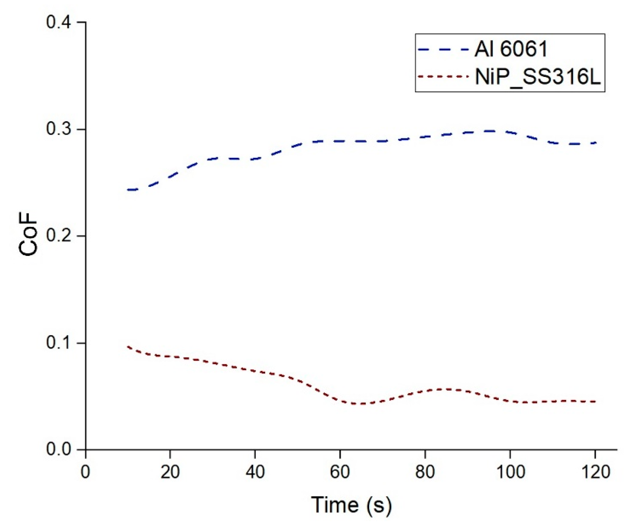
Figure 7 shows the coefficient of friction (CoF) in line polishing Al 6061 and NiP_SS316L. The CoF decreases for the NiP_SS316L surface. This finding is in line with the literature where it is stated that the coefficient of friction decreases with the increase in roughness of the counter surface [
13,
14].
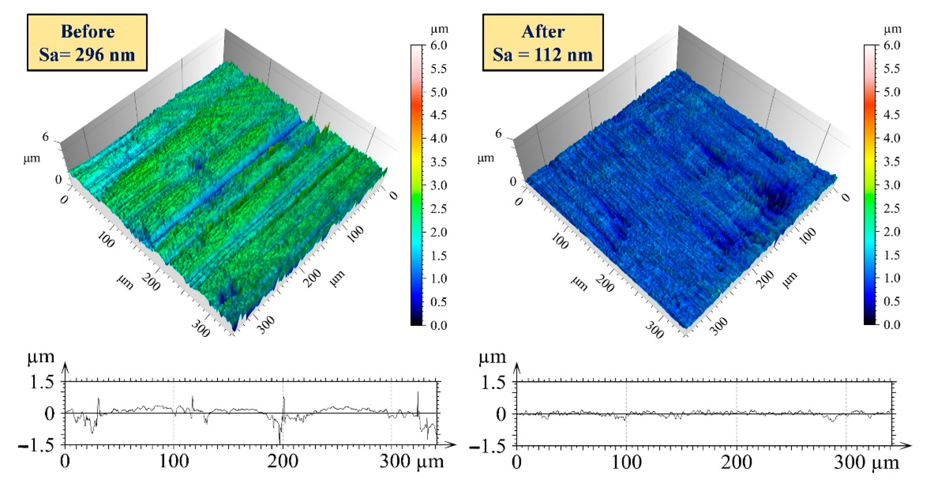
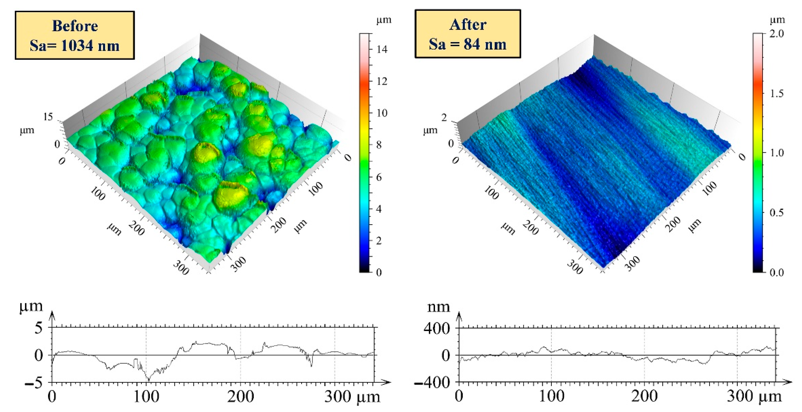
Figure 8 and
Figure 9 show the 3D surface profiles and 2D profile curves of the Al 6061 and NiP_SS316L surfaces before and after the line polishing experiment. The finishing is carried out in the direction perpendicular to the grinding marks on Al 6061. The percentage reduction in Sa is approximately 62% and 92% for aluminum and nickel-phosphorus-plated surfaces, respectively. The variation in the results can be related to the deeply indented abrasives being pulled out and adhered to the outer surface, resulting in an increment of the valley depth in the aluminum surface. However, the tool performs better on the nickel-phosphorus-plated surface as the higher surface peaks are removed relatively easily. Moreover, there is no sticking tendency on this surface like aluminum, which results in better interaction of the abrasives and consistent material removal from the nickel-phosphorus-plated surface. These findings will be evaluated with the bearing area curve, the characterization of the tool, and the finished surfaces.
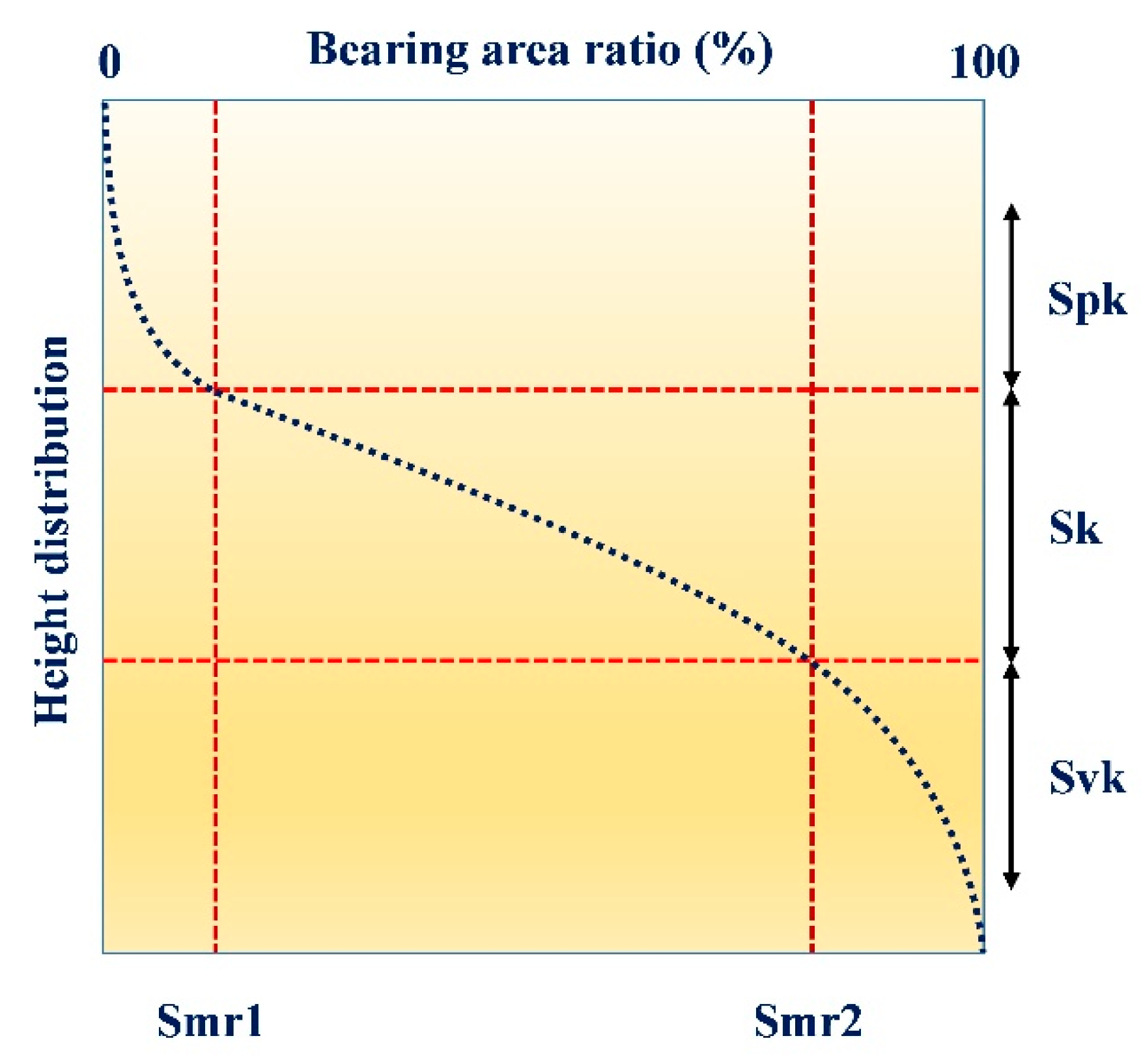
The bearing area curve (BAC), also known as the Abbott–Firestone curve or areal material ratio curve, is related to functional parameters used for analyzing the topography of the surface [
24]. The schematic of BAC is shown in
Figure 10, and the description of functional parameters is listed in
Table 3.
This curve gives information on functional behaviors like lubrication retention capacity, surface peaks and asperities, and the effective contact area between mating parts depending on the wear of the surface. Kumar et al. [
25] used BAC to estimate the component wear by implementing the numerical procedure for depth calculation. The wear will change the topography of the surface as well as introduces deformation in the surface [
26].
The bearing area curves of Al 6061 and NiP_SS316L surfaces are shown in
Figure 11 and
Figure 12, respectively. The proportion of the reduced valley depth is increased on the aluminum surface after the line polishing experiments. It confirms that though the surface is getting finished, it undergoes deeper abrasive indentation, which translates to abrasive wear of the surface. On the other hand, the reduced valley depth portion is decreased in the nickel-phosphorus plated surface after the line polishing experiment. It suggests that material is being sheared off quickly, and it reduces the level of core roughness and simultaneously reduces the valley depth. Furthermore, the skewness and the kurtosis of the counter surface play an important role in establishing contact between the surface and the flexible tool. The skewness (Ssk) is defined as the asymmetries of the surface height distributions from the mean plane. If the surface has a symmetrical distribution of peaks and valleys, it has zero skewness. If the surface has an uneven peak height and valley depth distribution, it is called a positive or negative skewed surface, respectively. The higher positive skewness is associated with a higher initial wear rate, whereas higher negative skewness is responsible for better fluid retention capacity.
The sharpness of the asperities on the surface can be examined by kurtosis (Sku). The Gaussian surface has a kurtosis value of 3. The surface with a kurtosis value greater than 3 has centrally distributed irregularities, whereas the equally distributed surface has a kurtosis value less than 3. The skewness and kurtosis values are studied to understand more about the distribution of the asperities and the sharpness of the peaks, as given in
Table 4. The higher kurtosis for the Al 6061 surface can be associated with abrasion by abrasive particles.
3.4. Characterization of the Used Tools
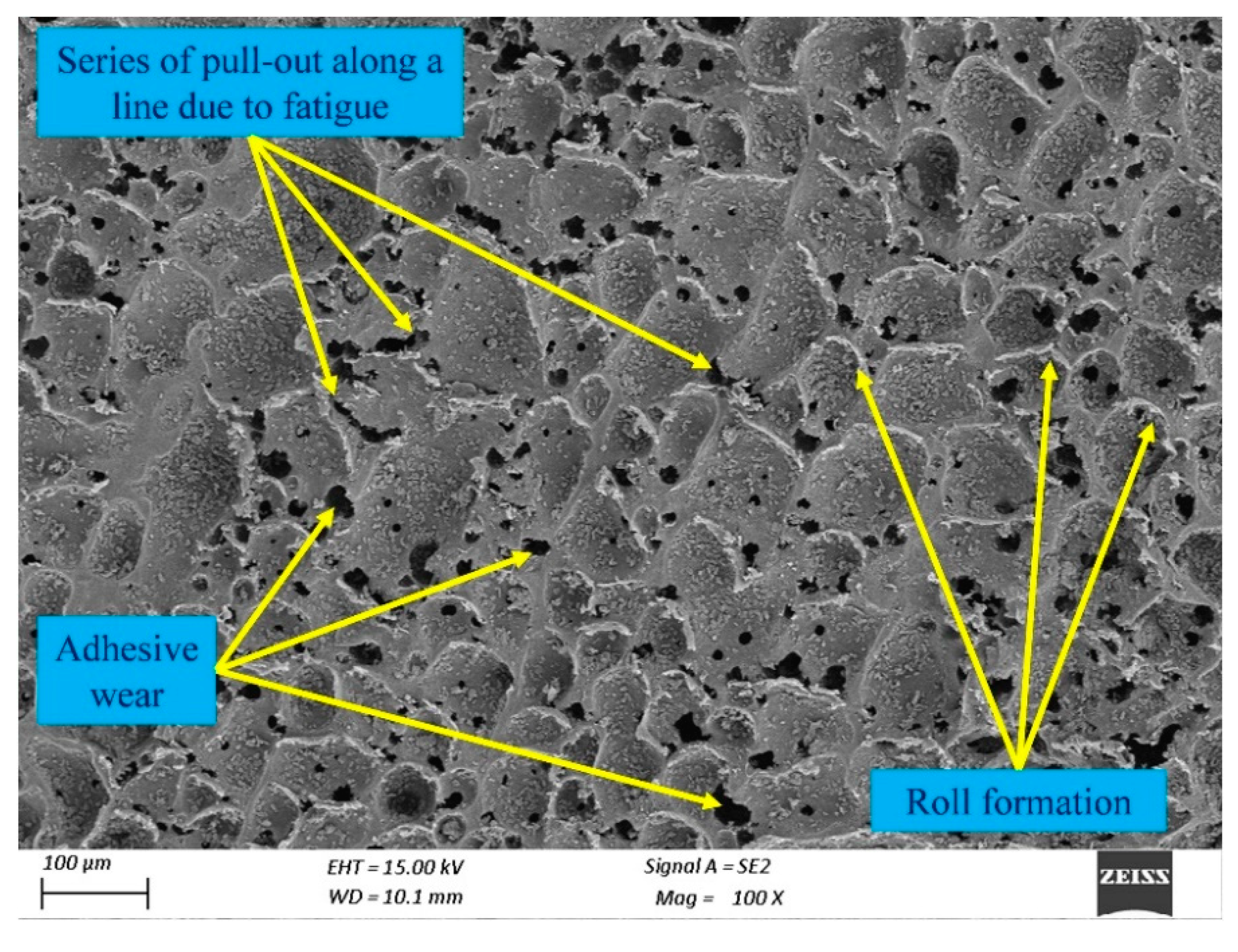
The wear mechanisms of the tool surface can be studied through SEM micrographs.
Figure 13 and
Figure 14 show the SEM images of the flexible abrasive tool used for line polishing Al 6061 and NiP_SS316L surfaces, respectively. The primary wear mechanisms observed in the tool used for the aluminum surface are adhesion, roll formation, and fatigue. It can be observed that the materials, along with abrasive particles, are being pulled out, resulting in the adhesive wear of the tool [
11]. The small ridges found around the tool surface are actually roll formations of the pulled material. In some places, it is observed that a linear void is created that can be termed fatigue of the outer surface of the tool. The intensity of the interaction between the abrasives and the soft tool will initiate surface degradation and material deformation [
27]. As the aluminum surface has difficulty in machining, it can be assumed that the surface and material properties also contribute significantly to the wear of the soft tool.
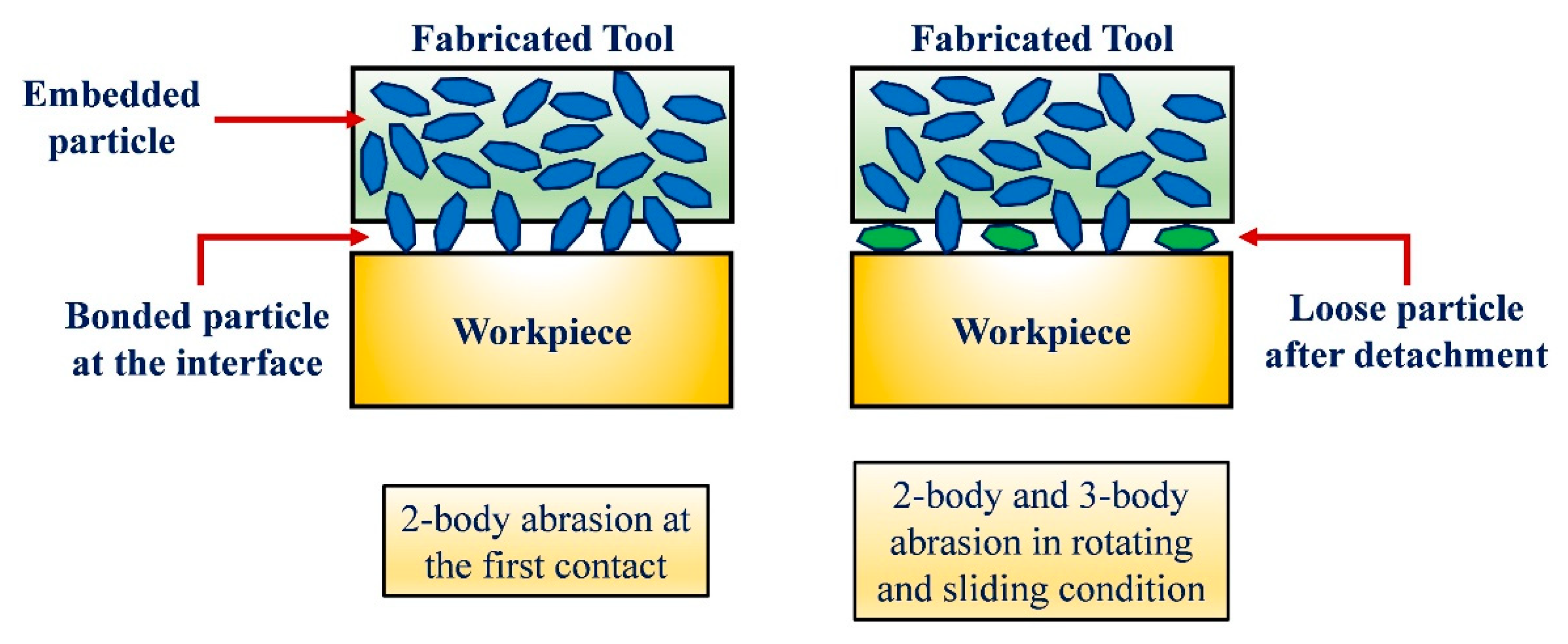
The primary wear mechanisms observed in the tool used for the nickel-phosphorus-plated surface are abrasion and roll formation. It can be observed that the abrasives are detached from the surfaces, indicating the wear of the surface. Roll formation is common, whereas detached abrasives create voids on the surface. It can be further explained as the cluster of blunt abrasive particles formed after detachment, resulting in abrasion of the soft tool. These detached abrasive particles are mostly blunt, and they do not affect the integrity of the finished surface much. This interaction between the soft tool, the loose abrasives, and the counter surface is called a three-body abrasion.
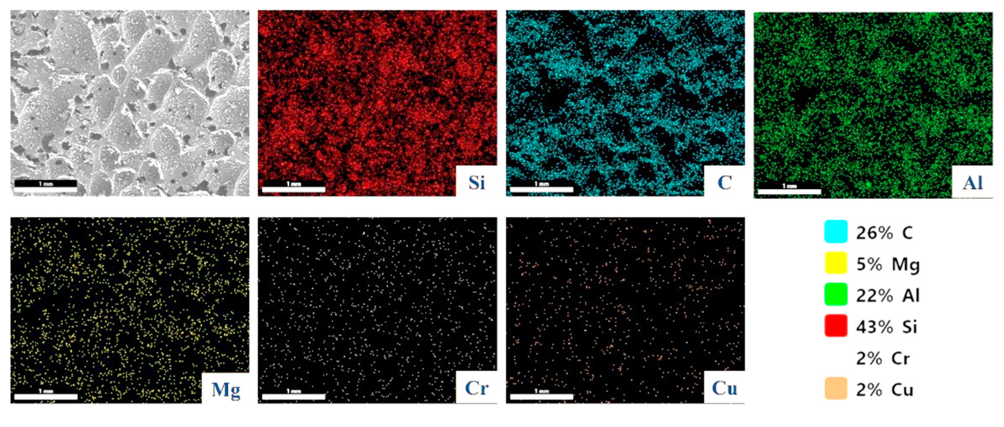
Elemental mapping of the tool utilized for the Al 6061 surface shown in
Figure 15 verifies the presence of aluminum alloy 6061 constituents. It supports the statement that the outer surface of the tool is loaded with chips. Additionally, the presence of abrasive particles shows that the tool is self-replenishing because they are also present on the outer surface and effectively remove the material from the surface.
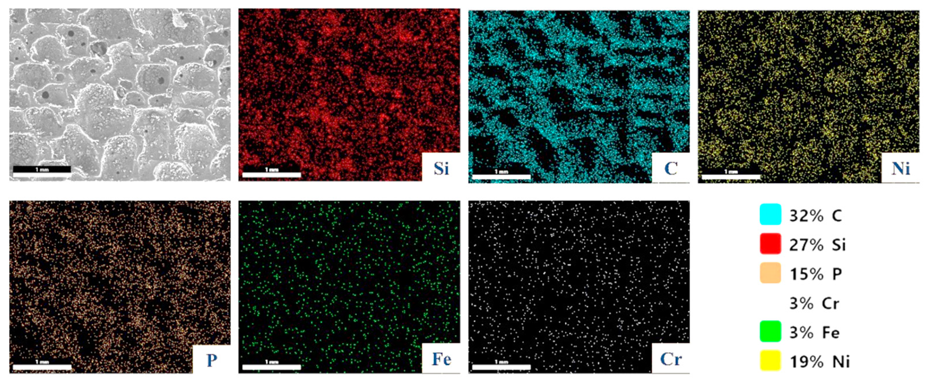
Similar findings are drawn using the elemental mapping of the tool used for NiP_SS316L shown in
Figure 16. Along with the iron and chromium particles, nickel and phosphorus are visible, indicating that the tool is loaded with the base material. The presence of abrasive particles following tool wear and loading is evidence of the self-replenishing capability. EDS can detect both major elements with concentrations higher than 10 wt.% and minor elements with concentrations of 1 wt.% to 10 wt.%. The constituents of workpiece material are observed in the elemental mapping of the used tool. Tools are soaked in DI water before finishing, but these tools are dried before the EDS. As a result, the chance of contamination with other materials other than constituents of workpiece materials is very less. A larger scan area is considered for
Figure 15 and
Figure 16 as compared to
Figure 5 because the used tool is likely to be loaded with chips, and it is difficult to capture abrasives, as well as the chips adhered to the surface precisely in a smaller scan area. The abrasive particles used in this study are of 4 µm size, and the scan area used in elemental mapping is much higher as compared to the abrasive size, so it can correctly capture the presence of abrasive particles.
The initial roughness of the counter surface plays a vital role in tool wear. The tool life is longer when used against a smooth and semi-rough surface. Moreover, the sliding distance has a significant impact on the wear rate [
28]. Different numerical simulations and analytical estimations are performed to predict the wear volume of elastomers based on parameters such as contact pressure, sliding velocity, and roughness of the counter surface. However, a still comprehensible prediction of elastomeric wear requires more extensive research on multiscale modeling [
19].
The weight loss ratio to the overall finishing time can be used to define the wear rate of the tool, as given in Equation (2).
Figure 17 shows the tool weight before and after performing the line polishing. The calculated wear rate for Al 6061 and NiP_SS316L is 10.625 mg/min and 23 mg/min, respectively. A correlation has been established between the initial roughness of the counter surface and the wear rate of the tool. The wear rate of the tool is almost twice when the initial areal roughness (Sa) of the electroless nickel-plated surface is 3.5 times that of the aluminum surface. However, tool wear is also affected by the mechanical and thermal properties of the workpiece. There is a chance that the elastomeric tool may soften as the portion of the heat generated due to friction between the tool and workpiece is transferred to the tool material, which in turn impacts the wear of the tool.
3.5. Contact Mechanics
The contact between the flexible tool and the workpiece is established by different surface asperities. These asperities support the total normal force acting on the contact interface. Each asperity will carry a fraction of this force. The total contact area
between the workpiece and the flexible tool is given by [
29]:
where
is the normal force and
is the workpiece hardness (in MPa).
Plastic deformation is predominant on the surface when shear stress exceeds the shear strength.
where
is the tangential force and
is the shear stress.
The coefficient of friction (CoF),
, is defined as the force ratio and denoted as:
The coefficient of friction is not only dependent on tool compression and rotational speed but also on the surface conditions and material properties of the contact. Adhesion and plowing occur when the contact between the tool and workpiece is established through the surface asperities. The minimum force required to shear the contacting asperities is called the adhesion force. When a hard abrasive particle indents into a relatively softer surface, it applies a plowing force. The sum of the plowing and adhesion forces is the total friction force. The transition between elastic and plastic deformation occurs when the shear stress exceeds the critical value. Beyond this point, the material deforms plastically. The tangential force acting at the interface is higher than the interatomic forces in the case of plastic deformation. During the finishing process, the abrasive particles in contact with the workpiece surface are responsible for three phenomena at the contact site. The primary action is the rubbing between the tool and workpiece pair without substantial material removal. It is followed by the plowing action, where the material is plastically deformed. The final action is cutting, where the material is removed due to shearing. The material removal in the flexible abrasive tool finishing depends on the indentation and shearing of the abrasive particles.
There are two stress components acting on the surface. The normal stress component (
) acts perpendicular to the surface, whereas the shear stress component (
) acts in the direction parallel to the surface. The stress components are dependent on the contact area.
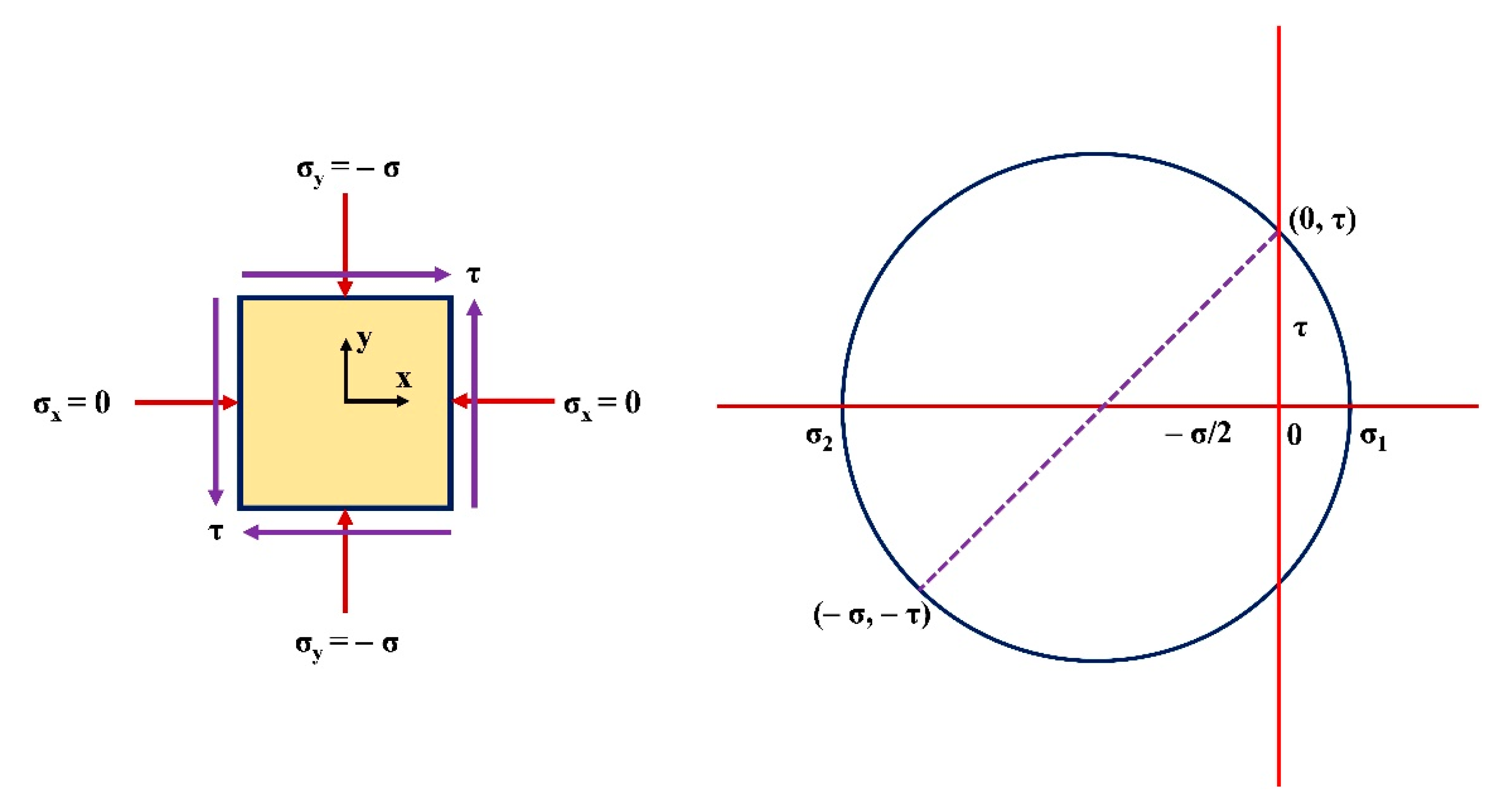
The tool is subjected to normal compressive stress and shear stress. The failure of a material occurs when shear stress is higher than the material’s shear strength. As aluminum is a soft material with a sticking tendency, the CoF is higher, as seen in the experimental data. The stress state of an element and Mohr’s circle are shown in
Figure 18.
From
Figure 18, Mohr’s circle radius is calculated as
The two principal stresses
and
can be obtained using the radius of Mohr’s circle as given by Equations (10) and (11).
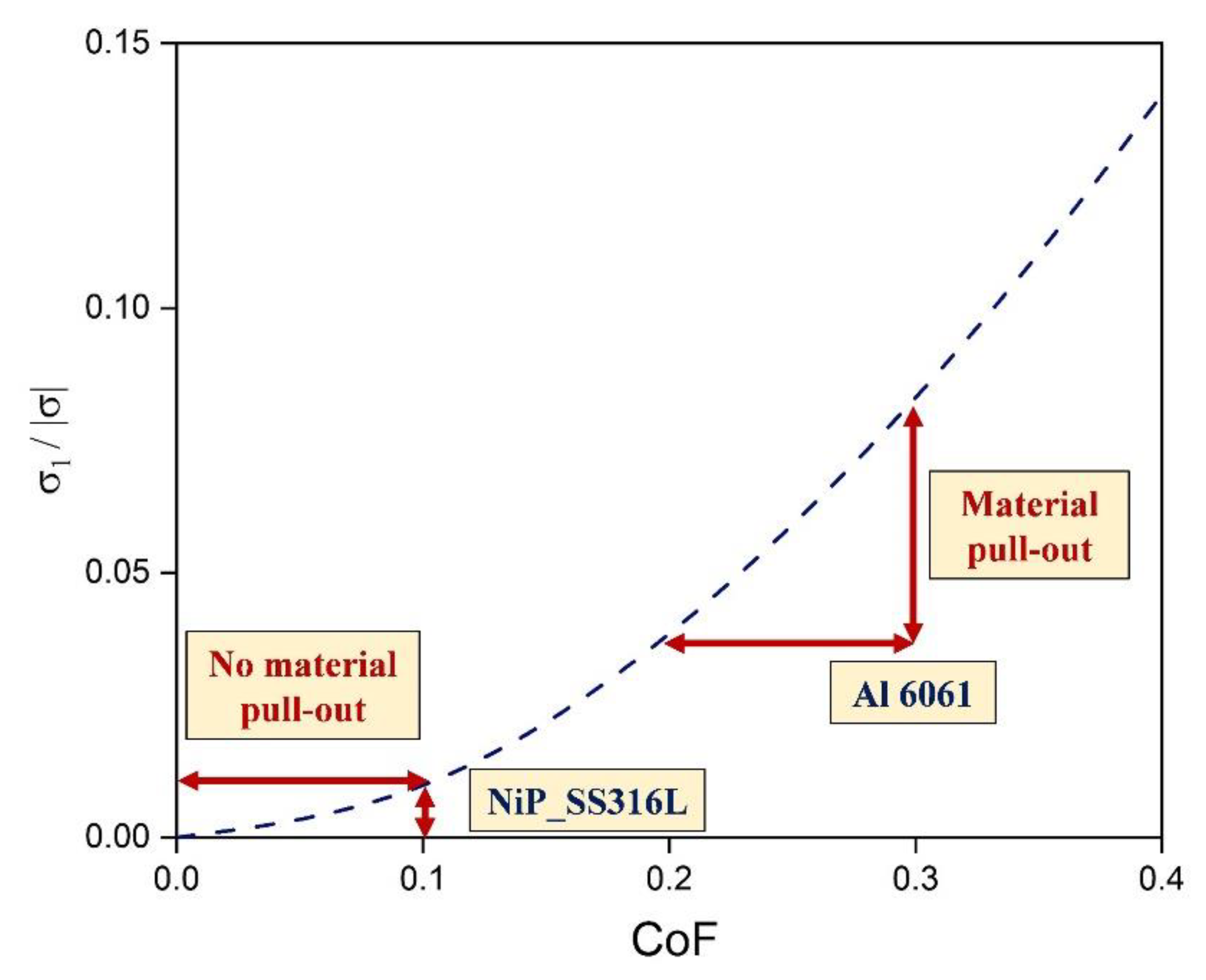
Using Equation (8), the principal stresses can be expressed in terms of the coefficient of friction
. Among the two principal stresses, the tool material is likely to fail due to the positive principal stress (
).
Figure 19 shows the ratio of principal stress to normal stress with respect to the coefficient of friction.
Tool material is likely to have pull-outs with an increase in frictional coefficient. A higher frictional coefficient is likely to alter the tool surface, thus affecting the performance of the tool. It can be concluded that the failure of the material is related to operating conditions and the properties of the counter surface. The hardness of the aluminum alloy is relatively lower than the electroless nickel-plated surface. Moreover, the tool wear can follow a similar trend if the shear stress component is higher than the critical value in the case of a nickel-plated surface.
