Article

Effect of Temperature and Sliding Velocity on the Dry Sliding Wear Mechanisms of Boron Modified Ti-6Al-4V Alloys

Mechanics of Materials Group, Department of Metallurgical Engineering and Materials Science, Indian Institute of Technology Indore, Indore 453552, India
*
Author to whom correspondence should be addressed.
Lubricants 2022, 10(11), 296; https://doi.org/10.3390/lubricants10110296
Submission received: 25 September 2022 / Revised: 31 October 2022 / Accepted: 1 November 2022 / Published: 4 November 2022
(This article belongs to the Special Issue Assessment of Abrasive Wear)

Abstract

:
The dry sliding wear behavior of as-cast pristine and boron-modified Ti-6Al-4V (Ti64) alloys (having 0.3 and 0.55 wt% B) is investigated using pin-on-disc experiments with the pin being Ti64 alloy and the EN31 steel disc. Experiments are performed at sliding speeds (s) of 1, 2, and 4 m/s and temperatures 300 and 573 K. A mixed response in wear behavior is observed. At the lowest sliding speed, all three alloys (except 0.55B alloy at 300 K) exhibit similar wear rates, with abrasive wear being the dominant wear mechanism. At 2 m/s, temperature and s increase, and adhesive wear takes over along with delamination wear. Here, the 0.55B sample shows the highest wear rate due to the debonding of more TiB particles, which increases three body abrasion wear. With further increase in s to 4 m/s, delamination and oxidation wear are observed for all the samples. XRD evaluation shows traces of TiO2 and Fe2O3, which imply the formation of MML in samples tested at s = 4 m/s, which is also validated through subsurface microstructure analysis. It is found that MML having more TiB particles has more stability, because of which 0.3B samples show higher wear rate.

1. Introduction

Titanium containing 6 wt% aluminum and 4 wt% vanadium (also referred to as Ti6Al4V or Ti64 alloy) is a workhorse of Ti alloys because of its superior mechanical properties (e.g., yield strength, fracture toughness, fatigue, and creep resistance) [1]. Hence, it is extensively used in aerospace, biomedical, and automotive industries just as other commercial Ti alloys [1,2,3,4,5,6]. However, they suffer from poor wear resistance that is attributed to (i) their low strain-hardening ability and (ii) relatively brittle surface oxide layer formed on the wear surface [7]. Ti64 is a dual-phase α   +   β alloy consisting of both low-temperature hexagonal close-packed α and high-temperature body-centered cubic β phases. The best combination of mechanical properties is offered by a refined microstructure comprising fine α and β laths which is typically obtained by the thermo-mechanical processing of the Ti64 alloy above the β -transus temperature. This elevated temperature wrought processing is expensive, and hence, significant emphasis was placed on alternate methods of grain refinement, of which trace additions of boron (B) to the Ti64 melt were found to be very effective [8,9]. It is observed that an addition of 0.1 wt% B to the Ti64 melt leads to a substantial reduction in the grain size and formation of TiB precipitates (when B content is above 0.04 wt%). The literature studies conducted on as-cast B modified Ti64 alloy thus far show that strength, elastic modulus, hardness, and creep resistance are increased with increasing B additions due to the refined grain, α / β lath size, and presence of TiB particles in the matrix [10,11,12,13,14,15]. The grain refinement tends to improve the hot workability of Ti64-xB alloys by reducing the temperature for mechanical working [12,13]. On the other hand, B addition has a malign effect on fatigue strength and fracture toughness as the TiB whiskers act as potential crack nucleation sites [14]. Overall, the addition of B has a mixed effect on the mechanical properties of Ti64-xB alloys [15]. It is interesting to investigate the tribological behavior of B modified Ti64 alloys as the components made of these alloys such as rotor bearings, rotating engine parts, and disc brakes experience contact loading conditions during their application [7,16].
Though a wealth of literature is available for understanding the tribological behavior of wrought Ti64 alloys, limited studies are available on the Ti64-xB alloys. In the case of wrought Ti64 alloys, it is observed that the microstructure (e.g., grain and lath size) along with sliding speed and temperature influence the wear mechanisms and the wear rate [2,17,18,19]. Dixit et al. [20] examined the dry sliding wear behavior of Ti64-xB (x = 0, 0.3 and 0.55 wt% B) alloys using pin-on-disc experiments (with the pin being the Ti64-xB alloy and the disc as EN31 steel) and found that the presence of TiB particles in the microstructure, in addition to the grain and lath sizes, markedly affected the wear mechanisms and thus the wear rate. Contrary to the expectations, the hardest Ti64-0.55B alloy showed the highest wear rate, and the wear surfaces showed severe delamination due to the three-body wear, with hard TiB particles participating in the wear and increasing the wear rate. One of the reasons for TiB particle pullout could be the large temperature gradient between the pin and disk (leading to high thermal stresses along the length of the pin) due to the heating of the pin alone.
It is interesting to examine the wear behavior and wear mechanisms for the pin and disk heated together, which is also likely the case in some real applications. Therefore, the current study aims to investigate the wear behavior of Ti64-xB alloys (x = 0, 0.3, and 0.55 wt% B) with both the pin and disk heated together in a heating chamber. Apart from this, the effect of sliding speed on the wear rate and prevalent wear mechanisms is also examined in detail.

2. Materials and Experiments

Three Ti64-xB alloys having 0, 0.3, and 0.55 wt% of B are used in the current study. All the alloys are produced by induction skull melting at Flowserve Corporation (Dayton, OH, USA) and further processing details are given in Ref [10].

2.1. Metallographic Analysis of Ti64-xB Samples

For metallographic analysis, cubic samples of 5 mm side length are sectioned from bigger blocks using wire electrical discharge machining (EDM). The samples are hot mounted, and the coarse polishing is performed using emery papers of various grit sizes followed by a final polishing using a diamond paste to achieve a surface finish of 0.25 µm. The specimen surfaces are then etched with Kroll’s reagent (92 mL distilled water, 6 mL HNO3, and 2 mL HF) to reveal the microstructure under the optical microscope (OM) and scanning electron microscope (SEM).

2.2. Wear Experiments

Wear experiments are performed using a pin-on-disc tribometer comprising a pin holder on which cylindrical Ti64-xB pins of 8 mm diameter are mounted. The pin comes under sliding contact with a rotating disc of 165 mm diameter made of EN31 hardened steel. The pin is placed at some offset distance from the center of the disc to obtain a wear track of 60 mm diameter. The linear variable differential transformer (LVDT) attached to the pin holder determines the reduction in height of the pin by which the amount of material worn is measured. The transverse force generated during the contact is measured using a piezoelectric sensor attached to the pin holder arm. The coefficient of friction is obtained by dividing the transverse force by normal force. All the experiments are performed at a normal load of 25 N and for a run time of 30 min. The disc is rotated at three different rotational speeds of 325, 650, and 1300 rpm with corresponding linear sliding speeds, s, of approximately 1, 2, and 4 m/s, respectively. The experiments are performed at two different temperatures, 300 and 573 K, with both the pin and disc covered with a heating chamber to provide a controlled heating environment.

2.3. Characterization of Wear Surfaces and Subsurface Deformation

The morphology of the wear surfaces is characterized using SEM and a contact profilometer. For profilometry, scanning is performed over a 2 × 2 mm surface area using a stylus having a tip radius of 2 µm. Amplitude parameter Rz, which is the average difference in height of five peaks and five valleys, is used to analyze the surface roughness [16]. X-ray diffraction (XRD) analysis is performed on the worn surfaces, and the diffraction patterns are obtained in the diffraction angle 2 θ range of 20 to 70°. The relative intensity vs. 2 θ plots are obtained after baseline correction and smoothening, and the diffraction peaks are identified using standard JCPDS files. The elemental analysis is performed on the wear surfaces using energy-dispersive X-ray spectroscopy (EDXS) analysis to find out the composition after the wear. To further understand the wear mechanisms and deformation morphology, a subsurface microstructural analysis is performed on the worn-out pins. The pin is sectioned in the middle and hot mounted in such a way that the subsurface region is exposed to the top, and the regions are examined in detail along the length of the sample using OM and SEM.

3. Results

This section may be divided by subheadings. It should provide a concise and precise description of the experimental results, their interpretation, as well as the experimental conclusions that can be drawn.

3.1. Microstructural Changes Due to B Addition

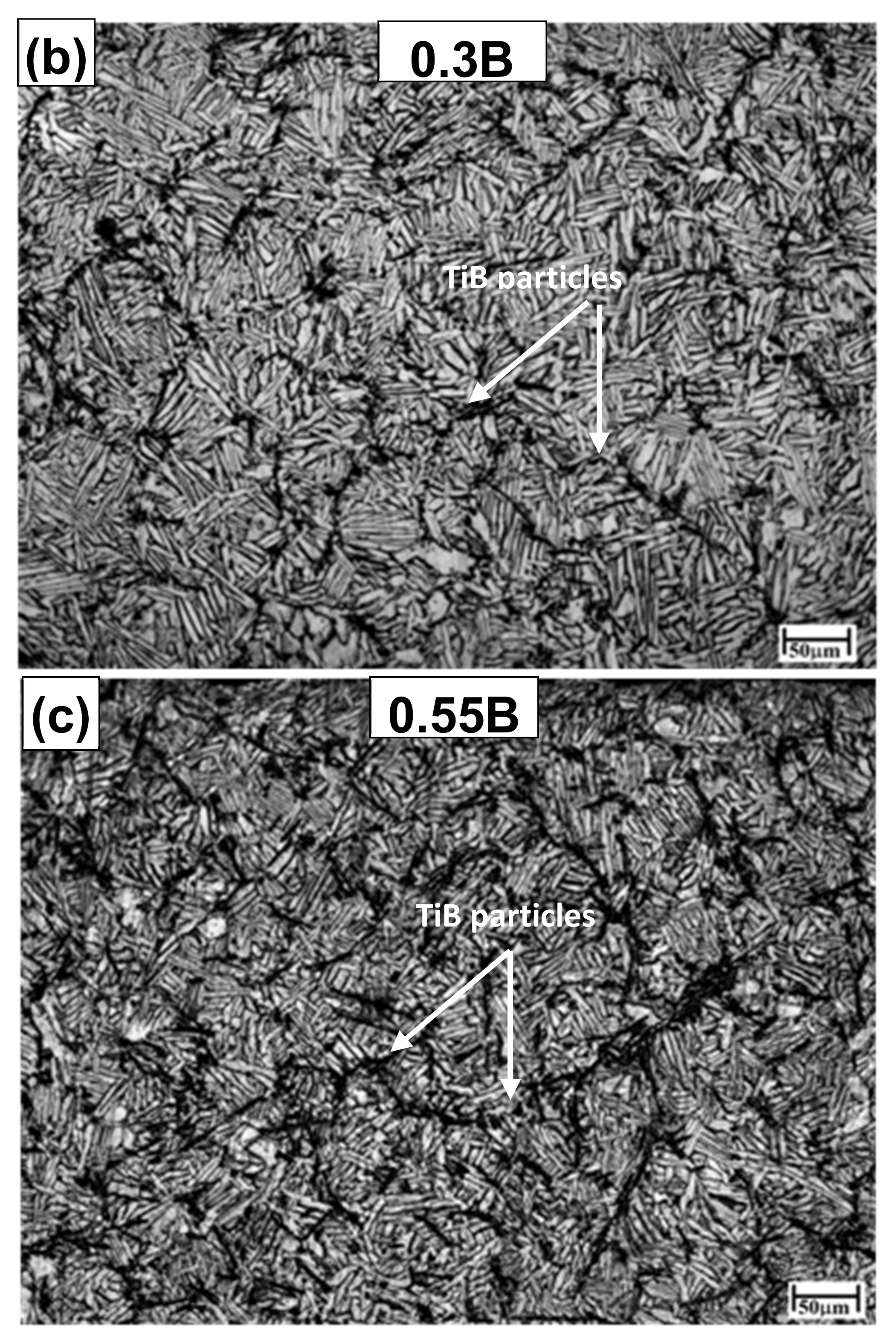
Representative optical micrographs of Ti64-0B, 0.3B, and 0.55B samples are shown in Figure 1a–c, respectively. It is evident from Figure 1 that the addition of B leads to a substantial reduction in grain and lath sizes along with the formation of TiB precipitates at the prior β grain boundaries in the alloys containing 0.3 and 0.55 wt% B (Figure 1b,c). The volume fraction of the TiB, size of α laths, and prior β grain size obtained from the Figure 1 are consistent with the literature studies [10,11,12,13,14,15,20] and are also presented in Table 1. The grain refinement is primarily attributed to the constitutional supercooling caused by the B addition. During solidification, the high-temperature β phase transforms into α   +   β phases with the formation of α laths along the prior β grain boundaries [1]. The transformation of β into 12 different variants of α takes place according to Burger’s orientation relationship: 0001 α // 110 β and 11 2 ¯ 0 α // 111 β [21]. At a time, only one of the variants is dominant, which results in the formation of an α colony, and in each grain, several such colonies originate from the grain boundary. According to the Ti-B phase diagram, boron has better solubility in the liquid Ti but has reduced solubility in the solid phase (up to only 0.02 wt%); hence, increased B leads to the formation of TiB precipitates at room temperature [9,22].

3.2. Variation of Wear Rate with Sliding Speed and Temperature

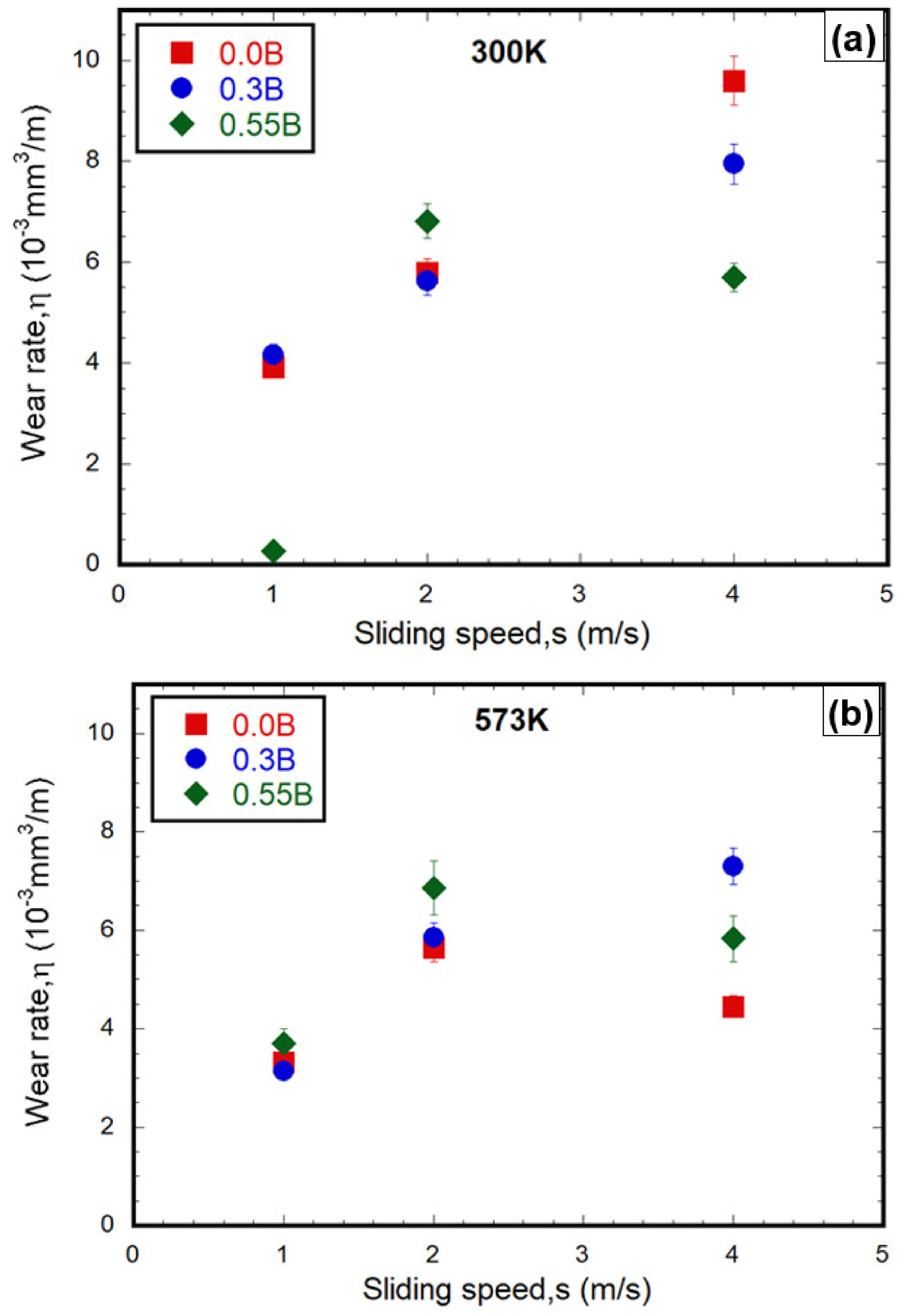
Wear rate η is defined as the volume of material loss from the pin, Vl, per meter of run. The Vl is computed as the product of the cross-sectional area of the pin and the decrease in height due to wear during the run time. The variation in η is plotted against the sliding speed, s, at 300 and 573 K and presented in Figure 2a,b, respectively. The following observations can be made from Figure 2:
(i)
Exceptionally low η is observed for 0.55B sample at s of 1 m/s and 300 K.
(ii)
Overall, the η for all the samples increases with increasing s from 1 to 2 m/s at both the temperatures.
(iii)
On transition in s from 2 to 4 m/s, the room temperature η for both 0B and 0.3B continues to increase, while it decreases for 0.55B. On the other hand, at 573 K, η decreases for both 0B and 0.55B samples, while it increases slightly for 0.3B.

3.3. Morphology of the Wear Surfaces

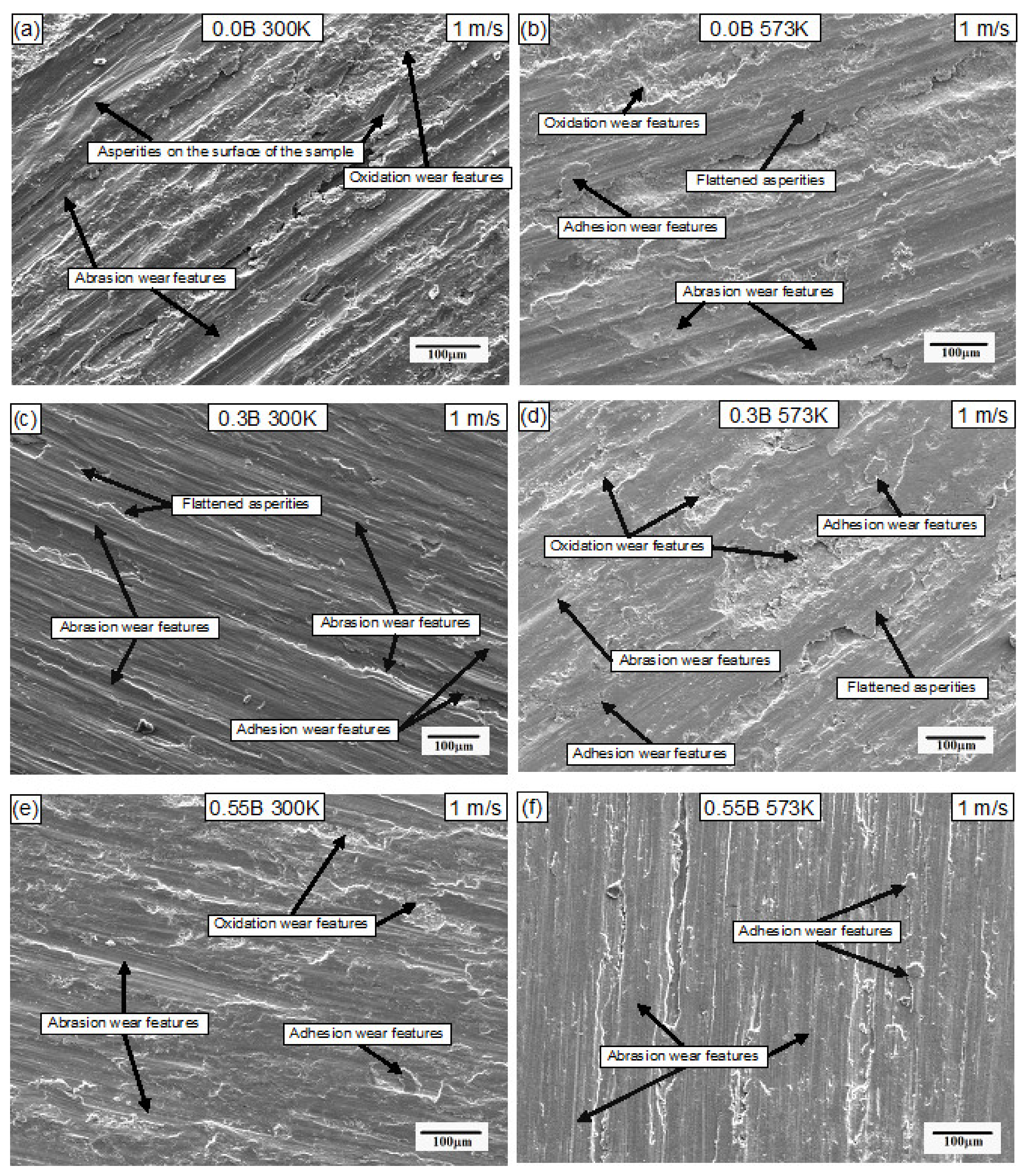
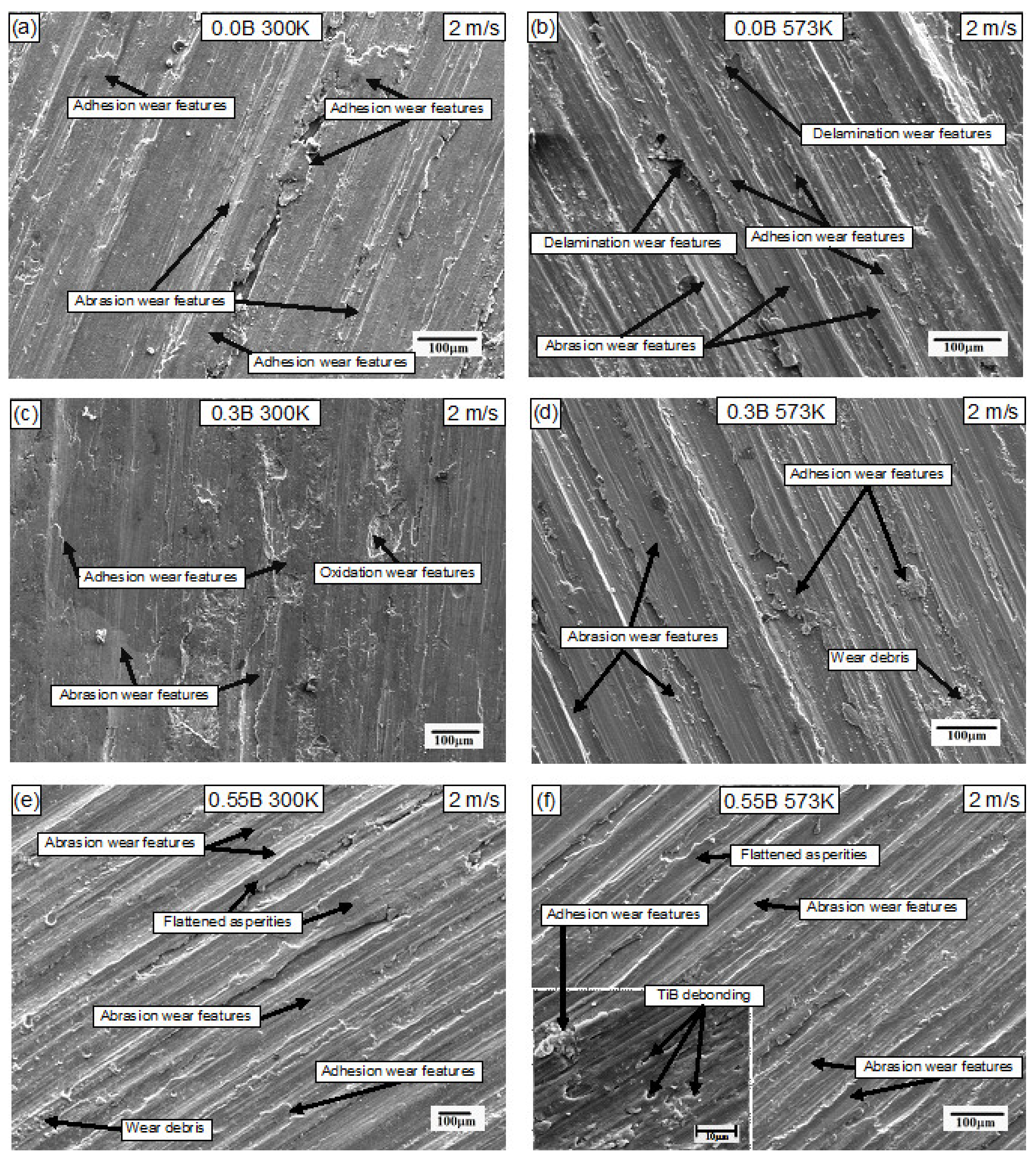
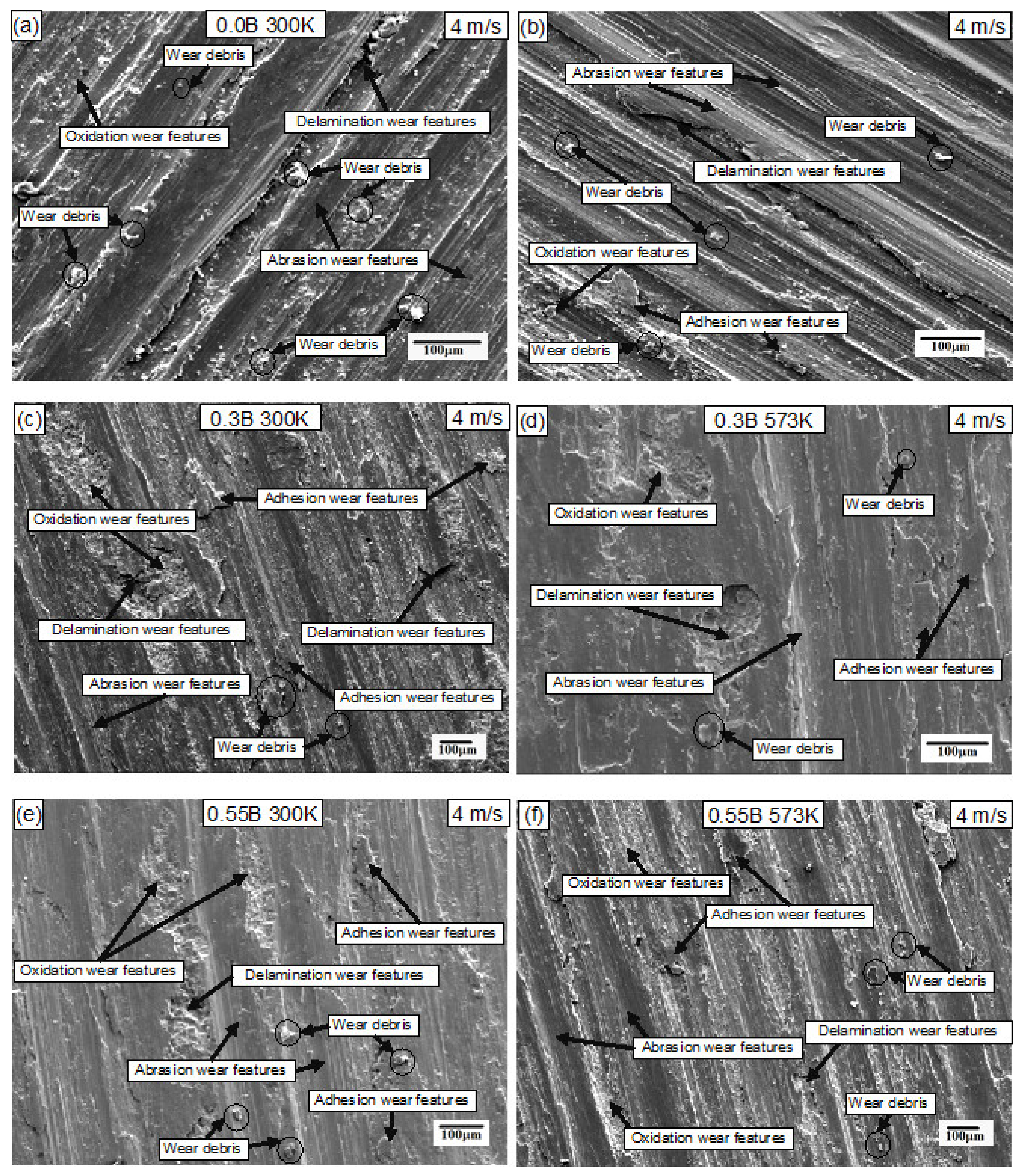
The SEM micrographs of the samples tested at s of 1, 2, and 4 m/s and temperatures of 300 and 573 K are presented in Figure 3, Figure 4 and Figure 5. At s of 1 m/s and both the temperatures, abrasive wear is the dominant wear mechanism as observed on the surfaces in Figure 3. The plastic shearing of asperities leads to the formation of grooves in all the samples, and in as-cast pure Ti64 alloy, additional oxidation wear features, albeit small, are also observed. In all the samples, as evident in Figure 3b,d,f, the dominant wear mechanism continues to be the abrasive wear. As s increases to 2 m/s, both abrasive and adhesion wear features are observed, resulting in an increase in η, and the adhesive wear features are more pronounced at 573 K, as displayed in Figure 4b,d,f. In addition to the adhesion and abrasive wear features, the debonding of TiB particles (as indicated by the arrows in Figure 4f) is also observed in the 0.55B samples at 573 K. At maximum s (=4 m/s), the wear surfaces are characterized by abrasive, adhesive, delamination, and oxidation wear features in all the samples. The wear surfaces of 0B samples are covered with micro fragments of wear particles (encircled in Figure 5a), and abrasive wear is predominantly seen (Figure 5a,b). The grooves are much deeper in this case compared with the wear surfaces of low and intermediate s, which is further confirmed by the profilometry images as displayed in Supplementary Materials (Figures S1 and S2). The wear surfaces of 0.3B samples at both temperatures contain profound delamination and oxidative wear features with significant material removal from the wear surface (Figure 5c,d), and similar features are observed in the 0.55B samples (Figure 5e,f) as well. Interestingly, in some regions, the microstructural features consist of TiB particle pullout as displayed in the inset figure of Figure 4f. Three-dimensional profilometer contours of the wear surfaces tested at 4 m/s at 573K are presented in Supplementary Figure S3. The Rz obtained at each sliding condition is presented in Table S1 of Supplementary Materials. It is observed that Rz changes less with s changing from 2–4 m/s than from 1–2 m/s, which also closely follows the trend as shown in Figure 2. The SEM micrographs also indicate that the oxidation wear features are most prominent at low and high s but are hardly present at intermediate s. These observations are also in corroboration with the XRD patterns, where no noticeable oxide peaks are present on the samples tested at 2 m/s (Figure 6b), while discernable oxide peaks are noticed at 1 and 4 m/s (Figure 6a,c). In addition to the TiO2 peaks, the wear surfaces of the samples tested at 4 m/s also show Fe2O3 peaks, which might have originated from the counterface material. Further, the presence of oxide particles of counterface material in the tribo layer (TL) implies the formation of a strong mechanically mixed layer (MML) comprising both pin and disc material. The elemental analysis using energy-dispersive spectroscopy also reveals the presence of elemental Fe substantiating the presence of Fe2O3 in the TL in the samples tested at 4 m/s (shown in Figure S4 of Supplementary Materials).

3.4. Microstructures of Subsurface Deformation Regions

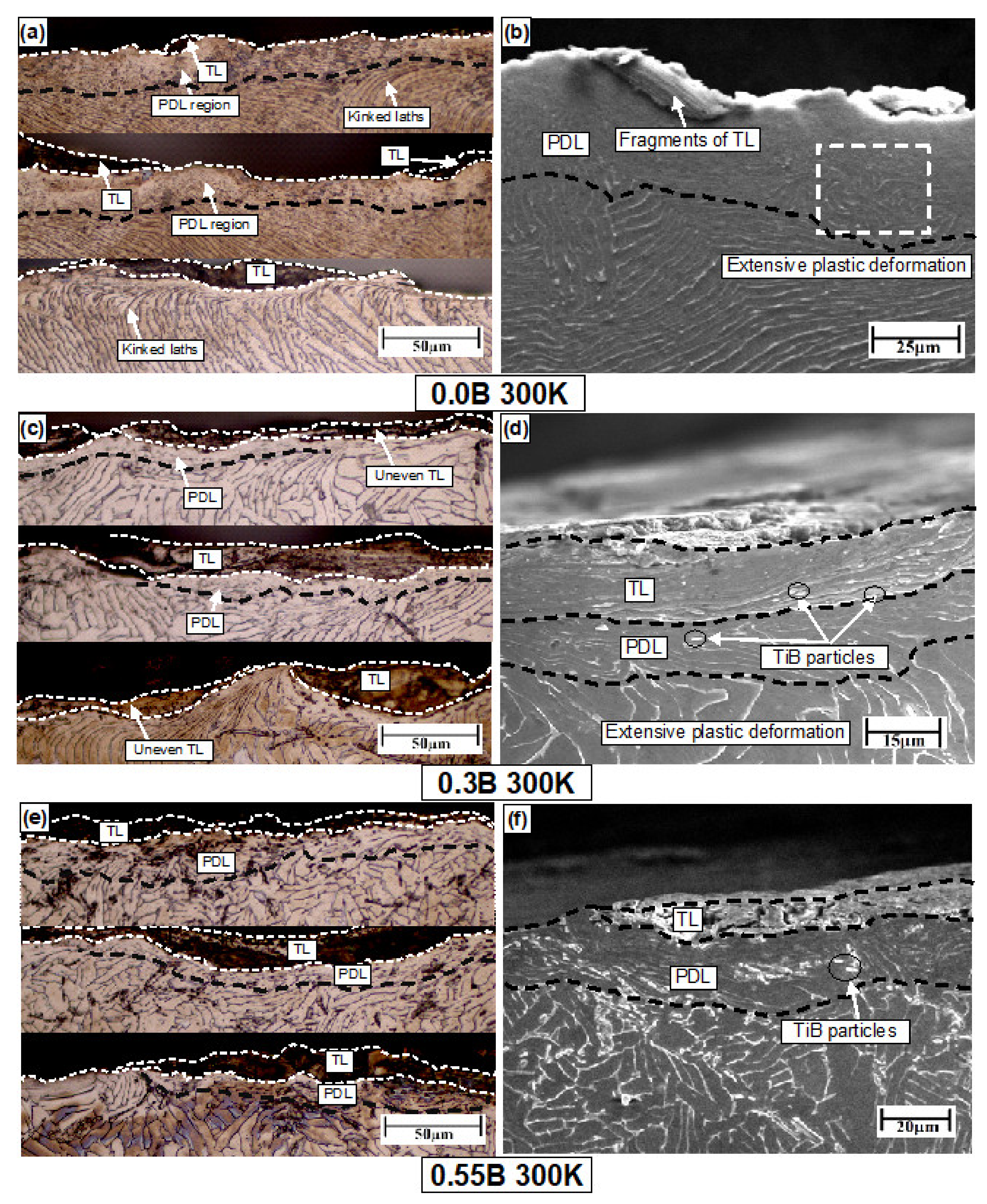
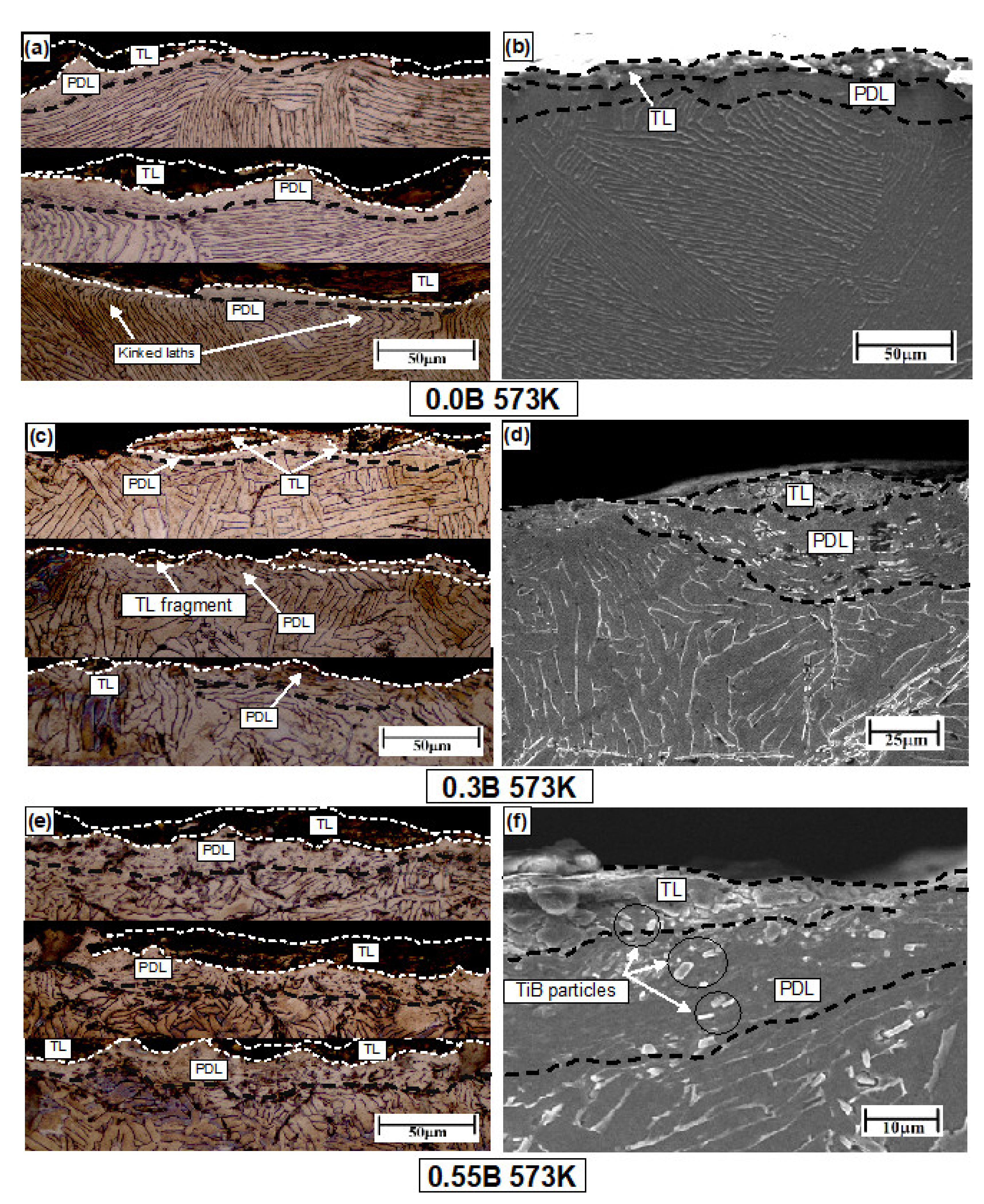
The subsurface microstructures of the samples tested at 4 m/s at temperatures 300 and 573 K are presented in Figure 7 and Figure 8, respectively, highlighting the key microstructural mechanisms prevalent during wear. The subsurface deformation regions can be divided into three layers: (i) the topmost layer, also referred to as the tribo layer (TL); (ii) the intermediate layer or plastically deformed layer (PDL); and (iii) the bottom-most layer or base layer (BL), corresponding to the undeformed matrix region. All the samples show the presence of TL and PDL, which varies with s and temperature as indicated in Figure 7 and Figure 8 for 300 and 573 K, respectively, at 4 m/s. The optical microstructures of the subsurface deformed regions obtained from three different locations on the worn surfaces (stitched together vertically) are presented in Figure 7 and Figure 8a,c,e for 0, 0.3, and 0.55B compositions, respectively, while Figure 7 and Figure 8b,d,f show the high-magnification SEM images of one location, highlighting the key deformation features. In both the microstructures, the hatched line is drawn as a guide for the eye to demarcate different subsurface deformation regions. Typical microstructural features consist of the oxidation of the surface layers and the severe kinking of laths, indicating extensive plastic shearing, deformation bands, fragmented TiB particles, and the TiB particle pullout regions. It is observed from Figure 7 and Figure 8 that the PDL layer comprises severely kinked fine laths due to large shear stresses, and the characteristics of both TL and PDL depend on the temperature. As shown in Figure 7a, 0B samples tested at 300 K have a discontinuous TL and a wide PDL zone (≈30 μm) with severe lath kinking, while at 573 K, a continuous and compact TL with a narrow PDL zone along with moderately kinked laths is observed (Figure 8a). Contrastingly, in the 0.3B samples (Figure 7b and Figure 8b) at both temperatures, the TL is uneven and discontinuous, while in the 0.55B samples, the TL is less uneven and fragmented.

4. Discussion

Wear is a complex process due to the interaction taking place between the two mating surfaces, and wear mechanisms such as abrasion, adhesion, oxidation, and delamination have a marked influence on the η. All the mechanisms are prevalent for a given combination of sliding speed and temperature, but the dominant one governs the net wear rate. In this section, the wear mechanisms and their origins are discussed in detail with a reference to the sliding speed and temperatures and are correlated with the trends observed in η.

4.1. Effect of Sliding Speed and Temperature on Wear Mechanisms and η

The prominent wear mechanisms, abrasion, adhesion, oxidation, and delamination, are observed together for all the sliding conditions; however, a few of them are more dominant than others for a given combination of temperature and sliding speed. It is very difficult to delineate the effects of temperature and s as high s tends to increase the interface temperatures due to frictional heating, which is difficult to measure using ex situ experiments. Hence, we present the discussion about various wear mechanisms taking place at any given s with increases in temperature.

4.1.1. Wear Behavior and Mechanisms at Lowest s = 1 m/s

At 1 m/s and 300 K, the 0.55 B samples exhibit the lowest η, which is probably due to their high hardness compared with the 0 and 0.3B samples. Under these conditions, there is an increased interaction of asperities present on the pin and disc surfaces leading to the flattening of the asperities. The plastic deformation, in this case, is confined only to the surface layers, and the heat generated due to friction between the pin and disk is insignificant [23]. For the same sliding speed at 573 K, the wear mechanisms appear to be similar (continue to be dominated by abrasive wear) and mild. Therefore, the wear surface features presented in Figure 3 are typical of abrasion wear in which the asperities of the hard surface (counterface material) dig into the softer material, and the material removal mainly takes place by plowing, leading to the formation of grooves on the wear surface [24]. According to Archard’s law, abrasive wear to a large extent is governed by the hardness of the material [7], and hence at low s, the samples with the highest hardness (Ti64-0.55B) exhibit the lowest η. With increasing s from 1 to 2 m/s, the frictional heat at the pin-disc interface increases, leading to the thermal softening of the pin and also causing additional wear mechanisms and thereby increasing the η. On comparing the current results with our previous work [20] on similar material and s (=2 m/s) but with the pin heating alone, a large reduction in η is observed at 573 K, which probably could be due to the thermal softening of the counter-face material [20].

4.1.2. Wear Behavior and Mechanisms at Intermediate s = 2 m/s

Unlike at low s, intermediate s (=2 m/s) increases the frictional heating at the pin-disk interface, leading to adhesion wear in addition to the abrasion wear as displayed in Figure 4a–c. Ti alloys have a strong tendency for material transfer (owing to their low thermal diffusivity) during the mating of surfaces, which was observed during the seizure of nuts and bolts made of Ti alloys [7,25]. During adhesion wear, short-range van der Waal forces generated between the sliding surfaces create a junction between the surfaces. These junctions are sheared due to relative motion, and the softer material is transferred to the counter surface and back to its surface again [24]. At low s and low temperatures, adhesion wear is not very significant but gradually increases with increasing s and temperature. According to Cui et al. [26], adhesion wear might also lead to abrasion wear due to the abrasive action of adhesive wear debris sticking out on the wear surface; therefore, abrasion and adhesion wear features are often seen together at high temperatures, as observed in Figure 4.

4.1.3. Wear Mechanisms at s = 4 m/s

At high s, the wear surface comprises oxidation, delamination, and abrasion wear, and η exhibits completely different trends at 300 and 573 K. At 300 K, η follows the trend η0.55B < η0.3B < η0B while at 573 K, the trend appears as η0B < η0.55B < η0.3B. At 300 K, the hardness of the alloy continues to be the dominant factor controlling η, and hence the hardest 0.55B alloy exhibits the lowest η. At high temperatures, there is an increased propensity for oxide formation, and the layer is more stable in 0B samples as there are no TiB particles in the microstructure to remove the oxide layer during the wear. This is not the case for the 0.3B and 0.55B samples, where the three-body wear promotes the removal of the oxide layer. In between the two samples, 0.55B experiences a lower η than 0.3B, which is intimately connected with the stability of the tribo layer between the two samples as explained in the subsequent section.

4.1.4. Common Wear Features between the Intermediate and High s

There are few common wear features between intermediate and high s. While abrasion and adhesion continue to be the wear features at both the sliding speeds, delamination wear is common to both, with more delamination at high s (as displayed in Figure 5) and a few locations in Figure 4. The mechanism of delamination wear involves the nucleation of subsurface cracks because of high traction force during the sliding of two surfaces. Owing to high image forces on the surface, the dislocations tend to pile up below the subsurface regions, resulting in high local stresses and the subsequent formation of cracks and microvoids. During the wear process, these cracks coalesce and grow parallel to the surface in the subsurface region and delaminate from the surface after a critical length [24,27]. Delamination wear also takes place due to three-body abrasion wear where the third phase particles (which are the oxide debris or debonded TiB precipitates) become trapped between the two rubbing surfaces causing excessive plowing, plastic flow, and groove formation [24] and eventually removing the material in the form of laminates. The high Rz value recorded in the profilometry images also demonstrates severe wear due to delamination.
The high temperature generated during frictional or external heating leads to oxidation of the surface and the oxide layer, depending on its stability, gets either removed during subsequent wear or acts as a lubricant. The oxidation wear features are prominent at high temperature and high s as presented in Figure 5 and similar features were reported in the literature [28]. Although the oxidation wear features are noticed on the wear surface, the diffraction peaks corresponding to them are not evident in XRD patterns (Figure 6). One of the reasons for this could be due to the push-off of brittle oxide particles from the interface due to high centrifugal force at high s. The high interface friction forces tend to remove the titanium oxide layer from the pin surface and thus leading to an increase in η. It is observed that the particles in the wear debris also oxidize, harden, and participate in the three-body wear mechanisms causing severe wear [7]. Therefore, delamination wear features are often seen along with oxidation wear features as in Figure 5, and it is observed that the increase in s causes a change in the wear mechanism from oxidation to delamination. These observations agree well with the literature studies on Ti alloys [29,30]. The increase in η at intermediate s is more prominent in the 0.3 and 0.55B samples (despite their high hardness), which could be due to the three-body wear where TiB particles promote the easy removal of the oxide layer from the pin surface.

4.2. Effect of Tribo-Layer Formation on Wear Behavior of Ti Alloys

The TL formed on the surface of the alloy has a marked effect on the wear behavior. The presence of traces of TiO2 and Fe2O3 on the wear surface (as shown in Figure 6c) at high s (and at both temperatures) indicates that severe mechanical mixing has taken place on the top surface layer, which is often referred to as the mechanically mixed layer (MML). MML is formed due to the mixing of oxides and fragments of mating parts having moderate hardness at a relatively high temperature; these layers are less stable due to the unfavorable Pilling–Bedworth ratios [31,32,33,34,35]. Mao et al. [33] observed an abrupt increase in η in Ti64 alloy in the temperature range of 25–200 °C as there is no protection due to TL, while the increase in η is more gradual above 200 °C due to the formation of protective TL. Similar observations were made by Wang et al. [36] in a Ti64-steel tribo system where excellent wear properties were observed at only around 400 °C due to protective MML formation. In agreement with this, the TL formed at 300 K was less stable than the one formed at 573 K (as shown in Figure 8b) for 0B samples at 4 m/s. One of the reasons for the increase in η for 0B alloys at 573 K compared with the 300 K is the relatively stable TL. The poor wear resistance of Ti64 alloys at low temperatures is generally attributed to the lack of formation of stable TL, and it is also observed that a critical temperature is needed for Fe2O3 to present in TL. TL formed below this temperature cannot achieve sufficient hardness and stability since it lacks enough oxides. Around the critical temperature range, there is a competition between the decrease in η due to the presence of stable oxides in TL and the increase in η due to thermal softening. Similar observations are even reported on the wear behavior of Ti64 alloys in previous literature [36]. Further, the sub-surface microstructure analysis shows the kinking of laths in the 0B samples (Figure 7a and Figure 8a) due to the high aspect ratio and severe plastic deformation (because of large shear stresses at the interface). The subsurface deformation zone is a common feature present in all the worn samples, but the depth of the PDL zone varies with the plastic flow characteristics of the samples; the counterface material; and operating conditions such as temperature, sliding speed, ambient atmosphere (vacuum or normal), and nature of the lubricant. The thickness of the PDL layer depends on the stability of TL, and a more stable TL leads to a less thick PDL as TL prevents the transfer of shear stresses to the matrix.
In addition to the tribo oxides, the TiB particles also provide improved wear resistance as long as they are present in TL; hence, they are deliberately added to the matrix, or the surface is often coated with the TiB or TiB2 compounds [37]. Thus, depending on their volume fraction in the base material, the presence of TiB particles either increases or decreases the η due to the competition between the three-body wear mechanisms and stabilizing the TL. At the highest s (=4 m/s), the heat generated is high enough to debond TiB particles, which along with oxides of wear fragments contributes to MML formation. Since 0.3B has a lower volume fraction of TiB particles, the TL formed has lower strength than TL formed in 0.55B.

4.3. Effect of the Counter Disc on the Wear Behavior

As the high-temperature experiments were conducted in a controlled heating environment, the thermal softening of the steel disc that occurred due to external and frictional heating (particularly at high s) also influenced η. At the same time, there was a lower thermal gradient between the pin and disc as both were maintained at the same temperature. Mao et al. [33] observed that at temperatures greater than 500 °C, η increases abruptly as the softening of Ti64 alloy overpowers the protection provided by TL, resulting in more delamination wear. Straffelini and Molinari [28] also investigated the wear behavior of a Ti64-AISI M2 steel tribo-pair and reported that contact temperature reached as high as 650 °C even at low s (=0.8 m/s), causing the thermal softening of both the pin and disc and leading to a transition in wear mechanism from oxidation to delamination. Further, in Ti64 alloys, an increase in temperature to 500 °C causes the decrease in yield strength from 950 to 450 MPa [38], suggesting a significant softening of the material. Similarly, for EN 31 steels, Pearson et al. [39] reported a significant drop in hardness (more than 40%) for an increase of 200 °C above 300 °C. Therefore, extensive wear to the EN 31 disc also occurs at s (=4 m/s), which results in Fe2O3 wear debris that contributes to MML formation (Figure 6c). Therefore, at high s, the combined effect of two opposing factors, i.e., the thermal softening of materials and the stability of the MML layer lead to differences in η for these materials. At 573 K and high s, the decrease in η compared with 300 K is attributed to the formation of an oxide layer and MML. As a concluding remark, we compared the current results with the commercial Ti64 alloys tested under similar conditions from the literature [26,33,40]. Although there are slight differences in maximum load, grain size, α -lath size etc., it appears from this comparison that the normalized η of the as-cast boron-modified Ti64 alloys tested at 1 m/s exhibit slightly lower η than the commercial Ti64 alloy having a grain size 300–600 µm.

5. Conclusions

The current experimental study shows that wear is a very complex phenomenon governed by the microstructure constituents of the alloy and external operating conditions such as sliding speed and temperature. The sliding speed, based on the magnitude, tends to increase the interface temperature (due to frictional heating) and thus affect the wear mechanisms and wear rate. An increase in interface temperature due to both frictional and external heating causes a transition from mild (abrasion) to severe wear (delamination). In boron-containing alloys, the TiB particles de-cohesioned from the matric promote the wear by causing three-body wear. However, when the conditions are optimum for MML layer formation (as in the case of s = 4 m/s), the debonded TiB particles become mixed in MML, giving it higher strength. Following are the detailed conclusions of this study.
  • At 1 m/s and 300 K, the wear rate η is governed by the hardness of materials, and hence, the Ti64-0.55B alloy exhibits the lowest wear rate and 0B alloy the highest η. In contrast, at 1 m/s and 573 K, the η of the 0.55B alloy increased abruptly due to the participation of TiB particles in the wear process, promoting the three-body wear.
  • At 2 m/s and 300 and 573 K, the η of 0.55B exhibits the highest rate as the three-body wear continue to be dominant and controls η.
  • At the highest s (=4 m/s), the increase in s from 2 to 4 m/s caused an increase in η in a few cases and a decrease in other cases depending on the temperature and composition, suggesting that multiple factors govern the wear behavior of these alloys.
  • At 300 K and low s, η follows the trend η0.55B < η0.3B < η0B. Mild abrasive wear is the dominant wear mechanism, which primarily depends on the hardness; hence, the hardest 0.55B samples exhibit the lowest η.
  • At 300 K and intermediate s, η follows the trend η0.55B < η0.3B < η0B. The increased wear resistance in the 0.55 and 0.3 B samples despite having the TiB particles is attributed to the small grain size observed in both samples compared with the 0B samples.
  • At 573 K and high s, η follows the trend η0B < η0.55B < η0.3B. The increased wear resistance of the 0B samples is attributed to the formation of a stable oxide layer which in the 0.55B and 0.3B samples is removed by the hard TiB precipitates.

Supplementary Materials

The following supporting information can be downloaded at: https://www.mdpi.com/article/10.3390/lubricants10110296/s1, Figure S1: 3 Dimensional profilometer topography of wear surfaces for experiments performed at s = 1 m/s for (a) 0.0B at 300 K, (b) 0.0B at 573 K, (c) 0.3B at 300 K, (d) 0.3B at 573 K, (e) 0.55B at 300 K, and (f) 0.55B at 573 K.; Figure S2: 3 Dimensional profilometer topography of wear surfaces for experiments performed at s = 2 m/s for (a) 0.0B at 300 K, (b) 0.0B at 573 K, (c) 0.3B at 300 K, (d) 0.3B at 573 K, (e) 0.55B at 300 K, and (f) 0.55B at 573 K; Figure S3: 3-Dimensional profilometer topography of wear surfaces for experiments performed at s = 4 m/s for (a) 0.0B at 300 K, (b) 0.0B at 573 K, (c) 0.3B at 300 K, (d) 0.3B at 573 K, (e) 0.55B at 300 K, and (f) 0.55B at 573 K; Figure S4: EDS spectrum of 0.55B sample tested at 573K at vs. = 4 m/s; Table S1: Tabulated representation of RZ for all the samples experimented at 300 K and 573 K for vs. = 1, 2 and 4 m/s.

Author Contributions

Conceptualization, methodology, formal analysis, investigation, writing—original draft preparation, T.D.; Conceptualization, resources, writing—review and editing, funding acquisition, K.E.P. All authors have read and agreed to the published version of the manuscript.

Funding

This research received no external funding.

Data Availability Statement

Not applicable.

Acknowledgments

We would like to thank U. Ramamurty, NTU Singapore, for lending the materials used in the work. We also would like to thank the Department of MEMS, IIT Indore, for providing the characterization facilities used in this work.

Conflicts of Interest

The authors declare no conflict of interest.

References

  1. Lütjering, G.; Williams, J.C. Titanium, 2nd ed.; Springer: Berlin/Heidelberg, Germany, 2007; ISBN 3-540-42990-5. [Google Scholar]
  2. Han, J.; Zhang, G.; Chen, X.; Liu, B.; Cai, Y.; Zhang, X.; Tian, Y. Fabrication and study of innovative Ni-added Ti–6Al–4V through directed energy deposition. Mater. Sci. Eng. A 2022, 856, 143946. [Google Scholar] [CrossRef]
  3. Yang, Z.; Wen, F.; Sun, Q.; Chai, L.; Ma, X.; Zhu, M. Strength-ductility improvement achieved by introducing heterostructured martensite in a Ti-6Al-4 V alloy. Mater. Charact. 2022, 192, 112230. [Google Scholar] [CrossRef]
  4. Çam, G.; Ipekoğlu, G.; Bohm, K.-H.; Koçak, M. Investigation into the microstructure and mechanical properties of diffusion bonded TiAl alloys. J. Mater. Sci. 2006, 41, 5273–5282. [Google Scholar] [CrossRef]
  5. Cam, G.; Clemens, H.; Gerling, R.; Kocak, M. Diffusion bonding of fine grained gamma-TiAl sheets. Z. Metallkd. 1999, 90, 284–288. [Google Scholar]
  6. Polishetty, A.; Nomani, J.; Littlefair, G. Effect of transus based heat treatment on material characterisation of wrought and additive titanium alloy Ti-6Al-4 V. Mater. Today Proc. 2022, 59, 1749–1753. [Google Scholar] [CrossRef]
  7. Philip, J.T.; Mathew, J.; Kuriachen, B. Tribology of Ti6Al4V: A review. Friction 2019, 7, 497–536. [Google Scholar] [CrossRef] [Green Version]
  8. Zhu, J.; Kamiya, A.; Yamada, T.; Shi, W.; Naganuma, K. Influence of boron addition on microstructure and mechanical properties of dental cast titanium alloys. Mater. Sci. Eng. A 2003, 339, 53–62. [Google Scholar] [CrossRef]
  9. Tamirisakandala, S.; Miracle, D.B. Microstructure engineering of titanium alloys via small boron additions. Int. J. Adv. Eng. Sci. Appl. Math. 2010, 2, 168–180. [Google Scholar] [CrossRef]
  10. Sen, I.; Tamirisakandala, S.; Miracle, D.B.; Ramamurty, U. Microstructural effects on the mechanical behavior of B-modified Ti–6Al–4V alloys. Acta Mater. 2007, 55, 4983–4993. [Google Scholar] [CrossRef]
  11. Sen, I.; Ramamurty, U. Elastic modulus of Ti–6Al–4V–xB alloys with B up to 0.55wt%. Scr. Mater. 2010, 62, 37–40. [Google Scholar] [CrossRef]
  12. Sen, I.; Ramamurty, U. High-Temperature (1023 K to 1273 K [750 °C to 1000 °C]) Plastic Deformation Behavior of B-Modified Ti-6Al-4V Alloys: Temperature and Strain Rate Effects. Met. Mater. Trans. A 2010, 41, 2959–2969. [Google Scholar] [CrossRef]
  13. Singh, G.; Satyanarayana, D.V.V.; Pederson, R.; Datta, R.; Ramamurty, U. Enhancement in Creep Resistance of Ti–6Al–4V Alloy Due to Boron Addition. Mater. Sci. Eng. A 2014, 597, 194–203. [Google Scholar] [CrossRef]
  14. Sen, I.; Gopinath, K.; Datta, R.; Ramamurty, U. Fatigue in Ti–6Al–4V–B Alloys. Acta Mater. 2010, 58, 6799–6809. [Google Scholar] [CrossRef]
  15. Singh, G.; Ramamurty, U. Reprint: Boron Modified Titanium Alloys. Prog. Mater. Sci. 2021, 120, 100815. [Google Scholar] [CrossRef]
  16. Blau, P.J.; Jolly, B.C.; Qu, J.; Peter, W.H.; Blue, C.A. Tribological Investigation of Titanium-Based Materials for Brakes. Wear 2007, 263, 1202–1211. [Google Scholar] [CrossRef]
  17. Feng, C.; Khan, T.I. The Effect of Quenching Medium on the Wear Behaviour of a Ti–6Al–4V Alloy. J. Mater. Sci. 2008, 43, 788–792. [Google Scholar] [CrossRef]
  18. Sahoo, R.; Jha, B.B.; Sahoo, T.K.; Sahoo, D. Effect of Microstructural Variation on Dry Sliding Wear Behavior of Ti-6Al-4V Alloy. J. Mater. Eng. Perform. 2014, 23, 2092–2102. [Google Scholar] [CrossRef]
  19. Hadke, S.; Khatirkar, R.K.; Shekhawat, S.K.; Jain, S.; Sapate, S.G. Microstructure Evolution and Abrasive Wear Behavior of Ti-6Al-4V Alloy. J. Mater. Eng. Perform. 2015, 24, 3969–3981. [Google Scholar] [CrossRef]
  20. Dixit, T.; Singh, I.; Prasad, K.E. Room and High Temperature Dry Sliding Wear Behavior of Boron Modified As-Cast Ti-6Al-4V Alloys against Hardened Steel. Wear 2019, 420–421, 207–214. [Google Scholar] [CrossRef]
  21. Burgers, W.G. On the Process of Transition of the Cubic-Body-Centered Modification into the Hexagonal-Close-Packed Modification of Zirconium. Physica 1934, 1, 561–586. [Google Scholar] [CrossRef]
  22. Palty, A.E.; Margolin, H.; Nielsen, J. Titanium-Nitrogen and Titanium-Boron Systems. Ph.D. Thesis, New York University, New York, NY, USA, 1954. [Google Scholar]
  23. Hsu, S.M.; Shen, M.C.; Ruff, A.W. Wear Prediction for Metals. Tribol. Int. 1997, 30, 377–383. [Google Scholar] [CrossRef]
  24. Menezes, P.L.; Nosonovsky, M.; Ingole, S.; Kailas, S.V.; Lovell, M.R. Tribology for Scientists and Engineers: From Basics to Advanced Concepts; Springer: New York, NY, USA, 2013. [Google Scholar]
  25. Budinski, K.G. Tribological Properties of Titanium Alloys. Wear 1991, 151, 203–217. [Google Scholar] [CrossRef]
  26. Cui, X.H.; Mao, Y.S.; Wei, M.X.; Wang, S.Q. Wear Characteristics of Ti-6Al-4V Alloy at 20–400 °C. Tribol. Trans. 2012, 55, 185–190. [Google Scholar] [CrossRef]
  27. Suh, N.P. The delamination theory of wear. Wear 1973, 25, 111–124. [Google Scholar] [CrossRef]
  28. Straffelini, G.; Molinari, A. Dry Sliding Wear of Ti–6Al–4V Alloy as Influenced by the Counterface and Sliding Conditions. Wear 1999, 236, 328–338. [Google Scholar] [CrossRef]
  29. Alam, M.O.; Haseeb, A. Response of Ti–6Al–4V and Ti–24Al–11Nb alloys to dry sliding wear against hardened steel. Tribol. Int. 2002, 35, 357–362. [Google Scholar] [CrossRef]
  30. Qin, M.; Zhang, Y.-Z.; Yang, J.-H.; Zhu, J. Microstructure and Tribological Characteristics of Ti–6Al–4V Alloy against GCr15 under High Speed and Dry Sliding. Mater. Sci. Eng. A 2006, 434, 71–75. [Google Scholar] [CrossRef]
  31. Pauschitz, A.; Roy, M.; Franek, F. Mechanisms of Sliding Wear of Metals and Alloys at Elevated Temperatures. Tribol. Int. 2008, 41, 584–602. [Google Scholar] [CrossRef]
  32. Raj, A.J.; Pottirayil, A.; Kailas, S.V. Dry Sliding Wear Behavior of Ti-6Al-4V Pin Against SS316L Disk at Constant Contact Pressure. J. Tribol. 2016, 139, 021603. [Google Scholar] [CrossRef]
  33. Mao, Y.S.; Wang, L.; Chen, K.M.; Wang, S.Q.; Cui, X.H. Tribo-Layer and Its Role in Dry Sliding Wear of Ti–6Al–4V Alloy. Wear 2013, 297, 1032–1039. [Google Scholar] [CrossRef]
  34. Alvi, S.; Neikter, M.; Antti, M.-L.; Akhtar, F. Tribological Performance of Ti6Al4V at Elevated Temperatures Fabricated by Electron Beam Powder Bed Fusion. Tribol. Int. 2021, 153, 106658. [Google Scholar] [CrossRef]
  35. Coddet, C.; Craze, A.M.; Beranger, G. Measurements of the Adhesion of Thermal Oxide Films: Application to the Oxidation of Titanium. J. Mater. Sci. 1987, 22, 2969–2974. [Google Scholar] [CrossRef]
  36. Wang, L.; Zhang, Q.Y.; Li, X.X.; Cui, X.H.; Wang, S.Q. Severe-to-Mild Wear Transition of Titanium Alloys as a Function of Temperature. Tribol. Lett. 2014, 53, 511–520. [Google Scholar] [CrossRef]
  37. Lee, C.; Sanders, A.; Tikekar, N.; Chandran, K.S.R. Tribology of Titanium Boride-Coated Titanium Balls against Alumina Ceramic: Wear, Friction, and Micromechanisms. Wear 2008, 265, 375–386. [Google Scholar] [CrossRef]
  38. Collings, E.W. The Physical Metallurgy of Titanium Alloys; ASM Series in Metal Processing; American Society for Metals: Almere, The Netherlands, 1984; ISBN 978-0-87170-181-7. [Google Scholar]
  39. Pearson, S.R.; Shipway, P.H.; Abere, J.O.; Hewitt, R.A.A. The Effect of Temperature on Wear and Friction of a High Strength Steel in Fretting. Wear 2013, 303, 622–631. [Google Scholar] [CrossRef]
  40. Li, X.X.; Zhou, Y.; Ji, X.L.; Li, Y.X.; Wang, S.Q. Effects of Sliding Velocity on Tribo-Oxides and Wear Behavior of Ti–6Al–4V Alloy. Tribol. Int. 2015, 91, 228–234. [Google Scholar] [CrossRef]
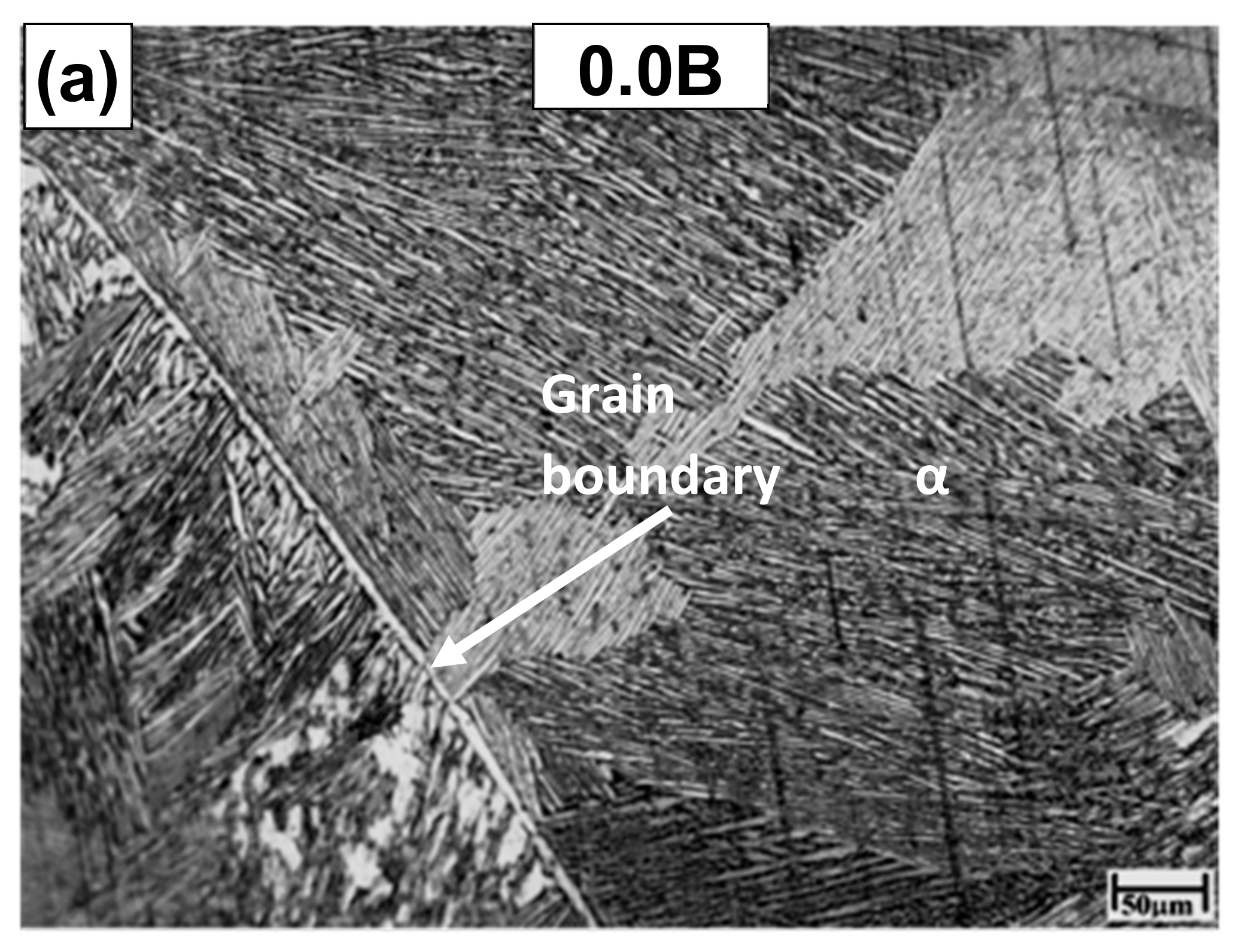
Figure 1. Representative microstructural features of Ti64-xB samples in following order (a) 0.0B, (b) 0.3B and (c) 0.55B.
Lubricants 10 00296 g001aLubricants 10 00296 g001b
Figure 2. Wear rate, η vs. sliding speed, s curves for all samples at (a) 300 K and (b) 573 K.
Lubricants 10 00296 g002
Figure 3. SEM images of wear surface displaying abrasion and related wear features for samples analyzed at s = 1 m/s for (a) 0.0B at 300 K, (b) 0.3B at 300 K, (c) 0.55B at 300 K, (d) 0.0B at 573 K, (e) 0.3B at 573 K, and (f) 0.55B at 573 K.
Lubricants 10 00296 g003
Figure 4. SEM images of wear surface displaying adhesion and wear features for samples analyzed at s = 2 m/s for (a) 0.0B at 300 K, (b) 0.3B at 300 K, (c) 0.55B at 300 K, (d) 0.0B at 573 (e) 0.3B at 573 K, and (f) 0.55B at 573 K.
Lubricants 10 00296 g004
Figure 5. SEM images of wear surfaces for samples analyzed at s = 4 m/s for (a) 0.0B at 300 K, (b) 0.3B at 300 K, (c) 0.55B at 300 K, (d) 0.0B at 573 K, (e) 0.3B at 573 K, and (f) 0.55B at 573 K.
Lubricants 10 00296 g005
Figure 6. XRD analysis of wear surfaces of samples analyzed at 300 K and 573 K for (a) s = 1 m/s, (b) 2 m/s, and (c) 4 m/s.
Lubricants 10 00296 g006aLubricants 10 00296 g006b
Figure 7. Subsurface analysis using optical microscopy (OM) and scanning electron microscopy (SEM) of wear experiments performed at 300K and s = 4 m/s sliding speed for (a) 0.0B (OM), (b) 0.0B (SEM), (c) 0.3B (OM), (d) 0.3B (SEM), (e) 0.55B (OM), and (f) 0.55B (OM).
Lubricants 10 00296 g007
Figure 8. Subsurface analysis using optical microscopy and SEM of wear experiments performed at 573K and s = 4 m/s sliding speed for (a) 0.0B (OM), (b) 0.0B (SEM), (c) 0.3B (OM), (d) 0.3B (SEM), (e) 0.55B (OM), and (f) 0.55B (OM).
Lubricants 10 00296 g008
Table 1. Tabulated values of grain size (d), α lath thickness (λα), and volume fraction of TiB (VTiB) in Ti64-xB samples.
Ti64-xBd (μm)λα (μm)VTiB (%)
02345 ± 4522.40
0.3121 ± 154.71.8
0.55103 ± 135.32.9
Publisher’s Note: MDPI stays neutral with regard to jurisdictional claims in published maps and institutional affiliations.