Article

CFD-Predicted Rotordynamic Characteristics for High-Temperature Water Liquid Seal Considering Tooth Deformation

1
School of Mechanical and Powder Engineering, Harbin University of Science and Technology, Harbin 150080, China
2
Chongqing Pump Industry, Chongqing 400033, China
3
School of Mechatronics Engineering, Harbin Engineering University, Harbin 150001, China
4
Department of Engineering Mechanics, Northwestern Polytechnical University, Xi’an 710072, China
5
School of Mechatronics Engineering, Harbin Institute of Technology, Harbin 150000, China
*
Authors to whom correspondence should be addressed.
Lubricants 2022, 10(10), 240; https://doi.org/10.3390/lubricants10100240
Submission received: 18 August 2022 / Revised: 15 September 2022 / Accepted: 23 September 2022 / Published: 28 September 2022

Abstract

:
With the development of high-temperature centrifugal pump, the temperature of the medium in the pump must be higher than the normal water temperature. It is particularly important to study the rotordynamic characteristics of the seal at high temperature due to it being the core component of the rotor system. This paper takes the high temperature water liquid seal as a research object to study its rotordynamic characteristics based on the fluid-solid-thermal coupling, the deformation of seal teeth under thermal and dynamic loads was calculated. Based on the test rig, the leakage flow rate and drag power loss of water liquid seal at 20 °C, 50 °C, and 86 °C temperatures were tested and compared with the CFD (Computational Fluid Dynamics) calculation. Meanwhile, the DEFINE-CG-MOTION and DEFINE-PROFILE control macro were used to establish the rotor whirling equation, the frequency-independent rotordynamic coefficients (K, k, C, c) and frequency-dependent rotordynamic coefficients (Keff, Ceff) were evaluated by transient CFD method. This analysis was done at three different pressure drops (2.08, 4.12, and 8.25 bar) and three rotational speeds (2000, 4000, and 6000 r/min). The results show that with the increase of water temperature, both the leakage flow rate and drag power loss decrease, indicating the 86 °C water seal has a better sealing capacity. From the rotordynamic perspective, with the increase of water temperature, the direct stiffness coefficient decreases, and the effective stiffness coefficient Keff for 20 °C water seal possesses a better stiffness capability than the other two temperature seals. The effective damping coefficient Ceff for 20 °C water seal is larger than the other two temperature seals, which means it is more stable for the rotor system.

1. Introduction

Reliable seals play an important role in the high-quality turbomachinery due to their influence on the leakage flow and the stability of the rotor system [1]. Seals can generate fluid response forces, which can either improve or degrade the stability of the rotor systems [2]. They are often the main source of instability, which has been confirmed by several laboratory tests [3]. Compared to the water-lubricated bearing [4,5,6,7,8], the water seal has a large clearance between the rotor and the stator, and there is also a large pressure drop between the two ends of the seal. Under the action of pressure drop and rotational speed, the flow inside the seal is generally turbulent. There are now many novel seal structures in the field of rotating machinery research, such as labyrinth-honeycomb seal, the pocket damper seal, the labyrinth seal with staggered helical teeth (SHT) structure, etc. [9,10,11]. Zhang et al. [12] proposed a novel anti-stagnation labyrinth seal structure. It was found that the new seal has better stability compared to the traditional labyrinth seal. Chen et al. [13] studied the effects of tooth bending length and the rotordynamic coefficients of labyrinth seals of after-damage clearance. For high-performance machinery, circumferentially grooved liquid annular seals are still the main configurations, especially in centrifugal pumps. Circumferentially grooved liquid annular seals with parallel grooves on the stator or rotor have the advantages of low leakage flow and allowing passage of solid contaminations [14]. However, the circumferentially grooved liquid annular seals also have the disadvantages of lower effective damping and smaller direct stiffness compared to the smooth liquid annular seals [15].
In the aspect of numerical calculation, many scholars used and developed the bulk-flow model to analyze rotordynamic coefficients of liquid annular seals. Iwatsubo [16] used the theory of the two-control-volume model to evaluate the rotordynamic coefficients of the parallel grooved annular seals. Marquette and Childs [17] developed three-control-volume bulk flow model. The main advantage of the bulk-flow model is fast calculation and certain calculation accuracy. However, its accuracy needs to rely on a large number of experiments to correct its empirical formula. With the development of computers, many scholars use CFD software to analyze the dynamics coefficients, Fengqin Li [18] used a single-frequency rotor whirling model to study the rotordynamic characteristics of a liquid annular seal. Generally speaking, the quasi-steady CFD-based method [19,20,21] and the transient CFD-based method based on the multiple-frequency rotor whirling models [22,23] are now the two advanced CFD methods in studying the circumferentially grooved liquid annular seals. The multiple-frequency rotor whirling model uses CFD dynamic mesh method, which requires a lot of computing resources and is prone to errors during the operation, the post-processing such as FFT transform is also required. The quasi-steady CFD-based method to calculate the rotordynamic coefficients for circumferentially grooved liquid annular seals with parallel grooves on the stator or rotor seems more suitable and more convenient. Once the whirling frequency changes, it needs to be calculated once, and finally, this method requires many times of calculations.
With the development of high-pressure and high-speed multi-stage centrifugal pumps, the temperature of the medium in the pump must be higher than the normal temperature. Not only that, the temperature of the fluid medium of some special pumps, such as plateau heat pumps, is also relatively high. However, most of the experiments and calculations of the liquid seal in the literature are based on the normal temperature [21,24,25,26], ignoring the influence of the liquid pressure, temperature, and rotor centrifugal force, for example, Li et al. [27] compared the rotordynamic characteristics of two types of liquid annular seals with parallelly grooved stator/rotor without considering the effects of the above three loads. Farzam [20] just gives the value of seal clearance under the thermal load, but detailed information is not given. With the change of the medium temperature, the properties of water will change, and its internal flow field will also be different, which can also influence the rotordynamic of the seal.
In this paper, our purpose is to understand the influence of different temperatures on the static and rotordynamic characteristics of water liquid seals. Based on the thermal-fluid-solid model, we calculated the deformation of the liquid seal under loads of pressure, centrifugal load, and temperature. A high-temperature seal test rig was established, the leakage and drag power loss of liquid water at different temperatures were measured, and the results were compared with the CFD simulations. To study the rotordynamic coefficients of high-temperature liquid seal, the CFD-based transient dynamic mesh method was used with the DEFINE-CG-MOTION and DEFINE-PROFILE control macros (User-Defined Function) introduced to establish the rotor whirl equation. The frequency-independent rotordynamic coefficients (K, k, C, c) and frequency-dependent rotordynamic coefficients (Keff, Ceff) under different operation conditions (three pressure drops, three rotational speeds) were obtained. The study paves the way for further study of rotordynamic characteristics of high-temperature liquid seal.

2. The Thermal-Fluid-Solid Coupling Model

2.1. Calculation Model

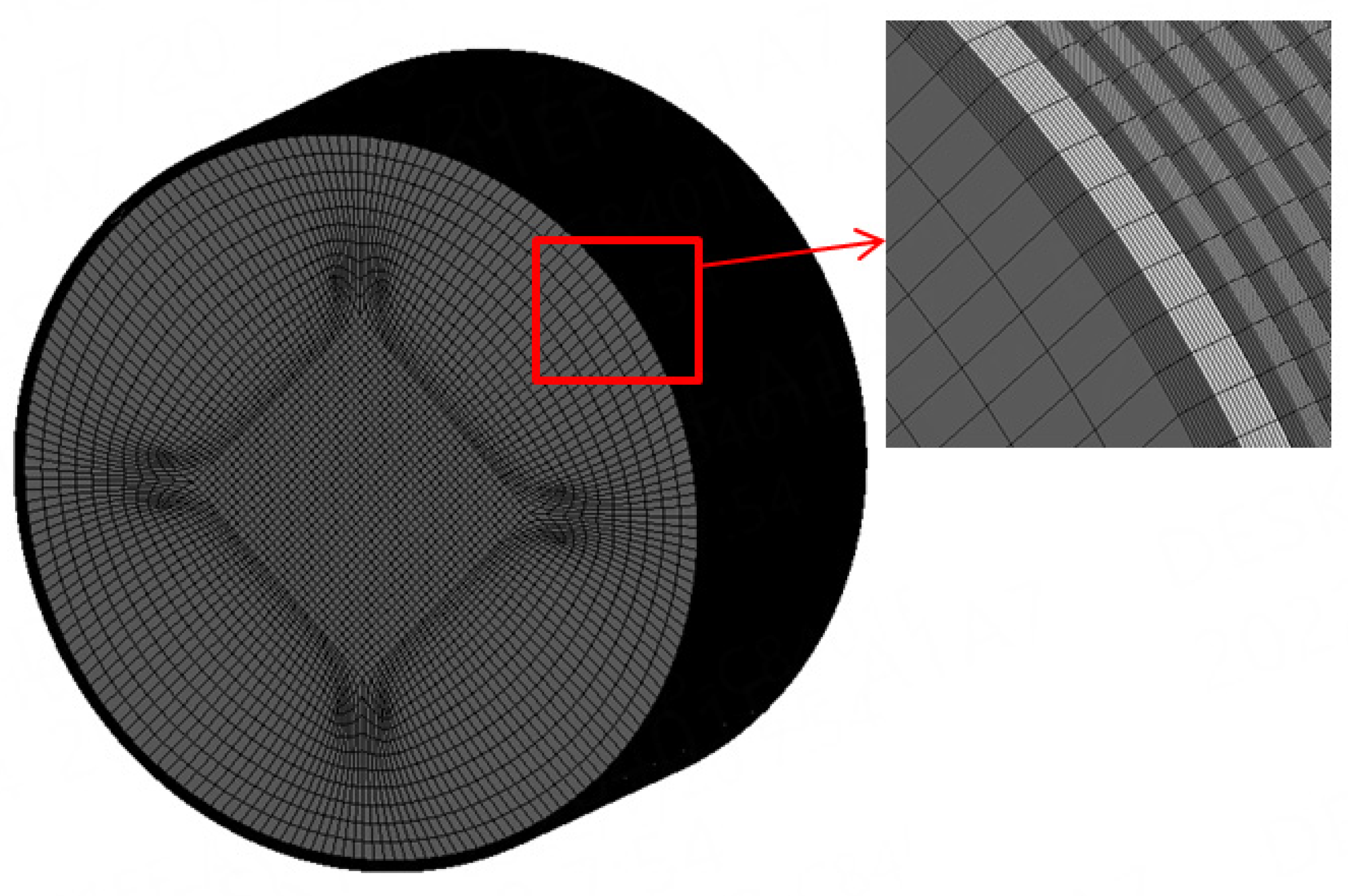
Since the temperature, the pressure, and centrifugal force will cause the deformation of the sealing tooth, in order to study the influence of the above parameters on the dynamic characteristics of the seal and obtain the real dynamic characteristics, this paper uses the thermal-fluid-structure coupling method to establish the fluid CFD model and solid FEM model, the Fluid CFD model is shown in Figure 1.
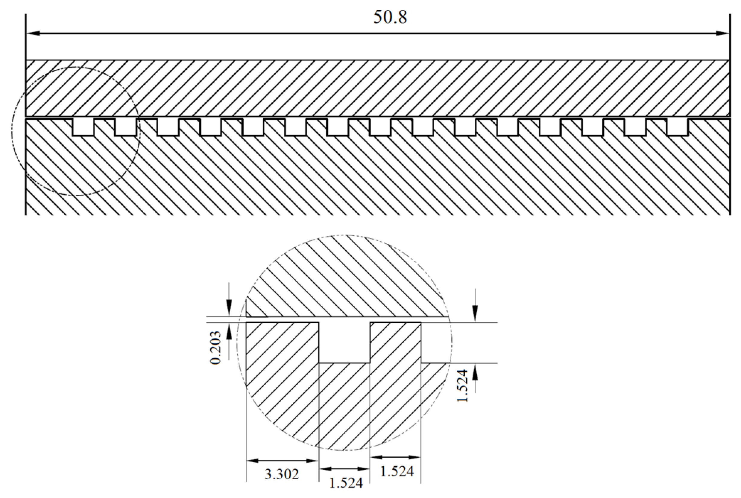
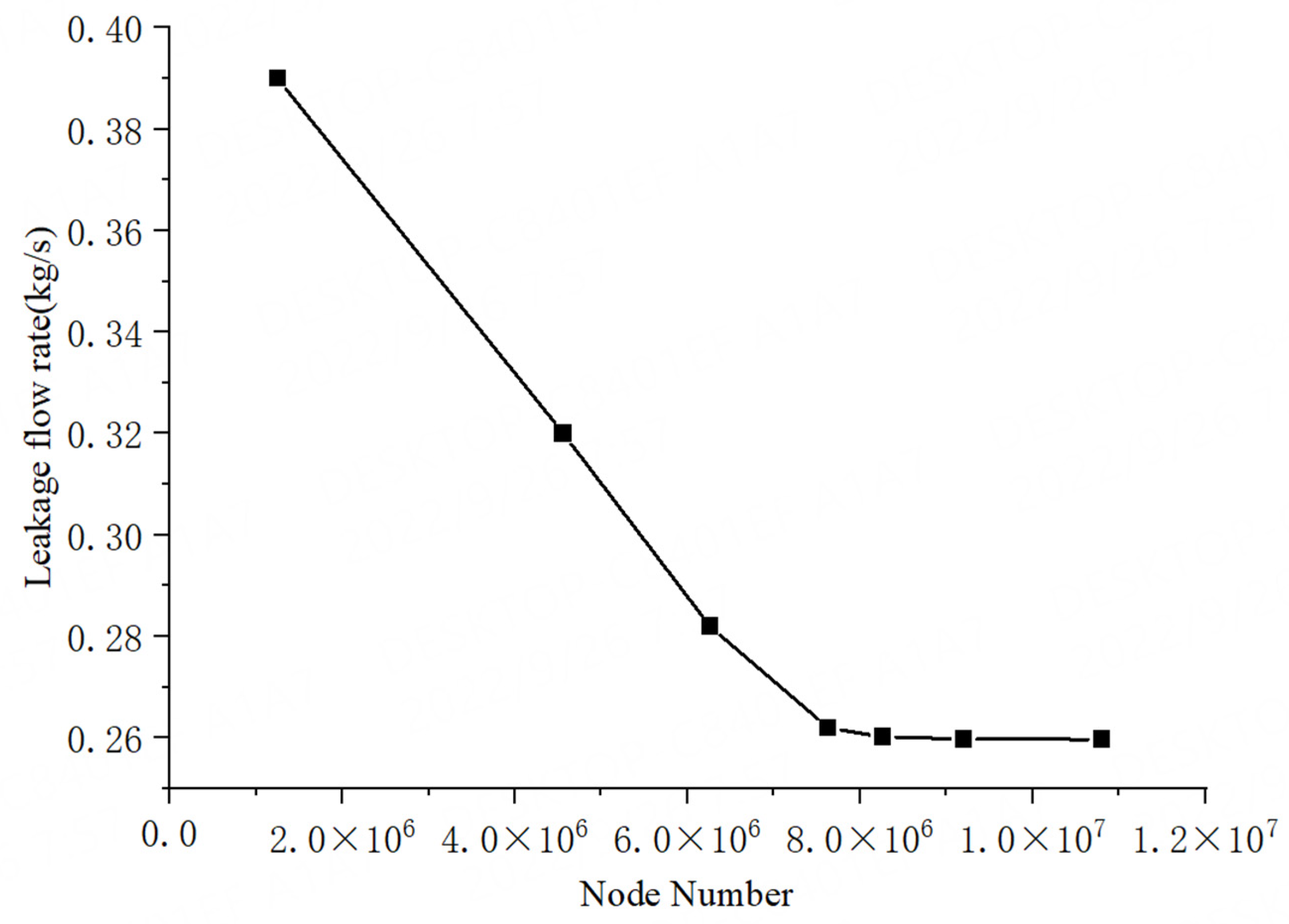
Table 1 gives the geometrical parameters and operational conditions in CFD analyses. The physical property parameters of three temperature water liquid are listed in Table 2. Figure 2 shows the geometry of the seal with parallel grooves on rotor. This analysis was done at three different pressure drops (2.08, 4.12, and 8.25 bar) and three rotational speeds (2000, 4000, and 6000 r/min). Figure 3 illustrates the computational model and mesh in fluent software [28]. The meshes are all hexahedral elements, and the mesh-independence study is done, which can be seen in Figure 3. The final mesh size of the CFD model used in this paper is 8,260,000 nodes. The turbulence model we use in this paper is k-ω SST. A pressure-based solver is chosen for the analysis. One side of the CFD model is used as a pressure inlet and the other as a pressure outlet. The pressure–velocity coupling is treated using the SIMPLEC algorithm. A second-order upwind discretization scheme is used for the momentum equations, and the QUICK discretization scheme is used for the volume fraction equation. A convergence tolerance of 10−4 is used for residual terms.
The mesh of the solid FEM model is shown in Figure 4. Both ends of the rotor model are constrained, except for the DOF of circumferential and radial directions. The mesh of the seal tooth surface is refined and set as the coupling interface. The material is 20Cr13, the elastic modulus is 207 Gpa, the Poisson’s ratio is 0.254, and the thermal expansion coefficient is 1.13 × 10⁻⁶ K−1.
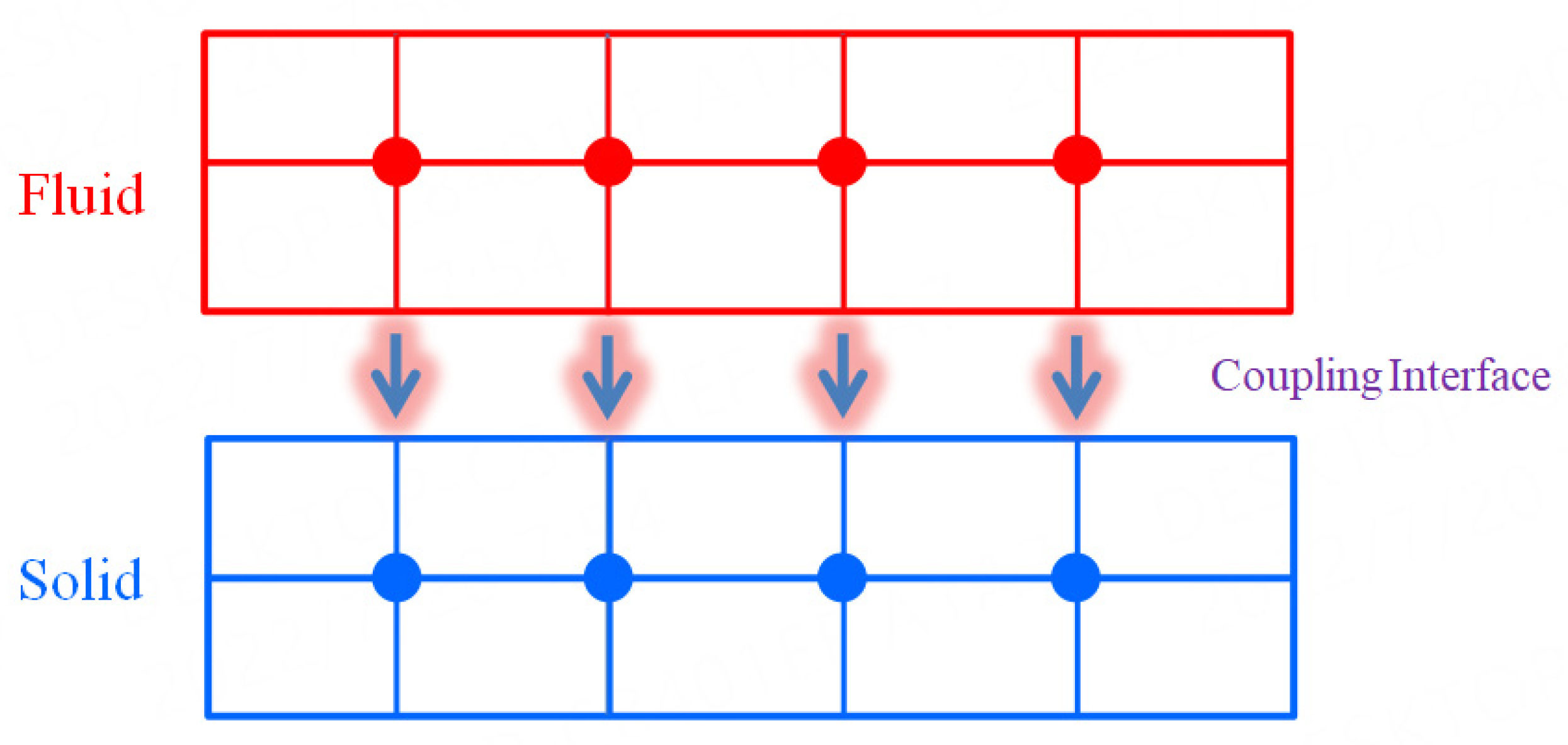
As shown in Figure 5, the pressure and temperature data of the fluid are imported into the solid seal structure model through the nodes on the coupling interface. In this model, the centrifugal effect of rotor rotation is considered, the static analysis of the solid seal structure is carried out, so the deformation of the seal teeth is obtained. The fluid-solid-thermal coupling calculation method flow chart used in this paper is given in Figure 6. When the calculation accuracy of the coupled model meets the accuracy requirements, the CFD and FEM models give the final results.

2.2. Seal Deformation Analysis

When coupling the pressure and temperature of the fluid field to the surface of the solid seal structure, the strain of the solid seal caused by the thermal load can be written as:
ε t = T [ λ x λ y λ z 0 0 0 ] T
T is temperature difference (K).
λ x , λ y , λ z are Vector expansion coefficients (K−1).
According to the effective length of the temperature effect, the thermal deformation of the material can be obtained:
L t = ε t h
h is the effective Length Matrix for Thermal Effects (m).
When the rotor rotates, the seal teeth are subjected to pressure and centrifugal force, resulting in a strain vector and deformation, respectively:
ε s = ε d ε t L s = R n ε s
where ε d is total strain vector; R n is rotation matrix of the element
So the deformation of the seal tooth is
L = L t + L s L r
L r is The deformation caused by the movement of the rigid body
The total deformation can be obtained from the deformation in each direction
L 0 = L 2 x + L 2 y + L 2 z
At this time, the seal clearance is
C = C r L 0
where C r is the initial seal clearance.
It can be seen from Table 3, Table 4 and Table 5 that the temperature has the greatest influence on the deformation of the seal teeth compared to the pressure drop and the rotational speed. When the water temperature is 20 °C, the radial deformation of the seal teeth is negative, and the magnitude of radial deformation and total deformation is in the order of 1 × 100.03 mm, which is much smaller than the deformation of the seal teeth at water temperature of 50 °C and 86 °C. We can almost ignore the deformation of the seal teeth of 20 °C temperature water.
The pressure and centrifugal force have little effect on the deformation. This is because the pressure mainly affects the axial deformation, hardly causing deformation in the radial direction. The rotational speed of the centrifugal pump is not too high, so the centrifugal effect is not obvious. It can be seen from Table 4 and Table 5 that the total deformation and radial deformation are approximately equal. Therefore, in terms of the influence of temperature, pressure, and centrifugal force on the dynamic characteristics of the seal, this paper mainly considers the influence of the radial deformation of the seal teeth.
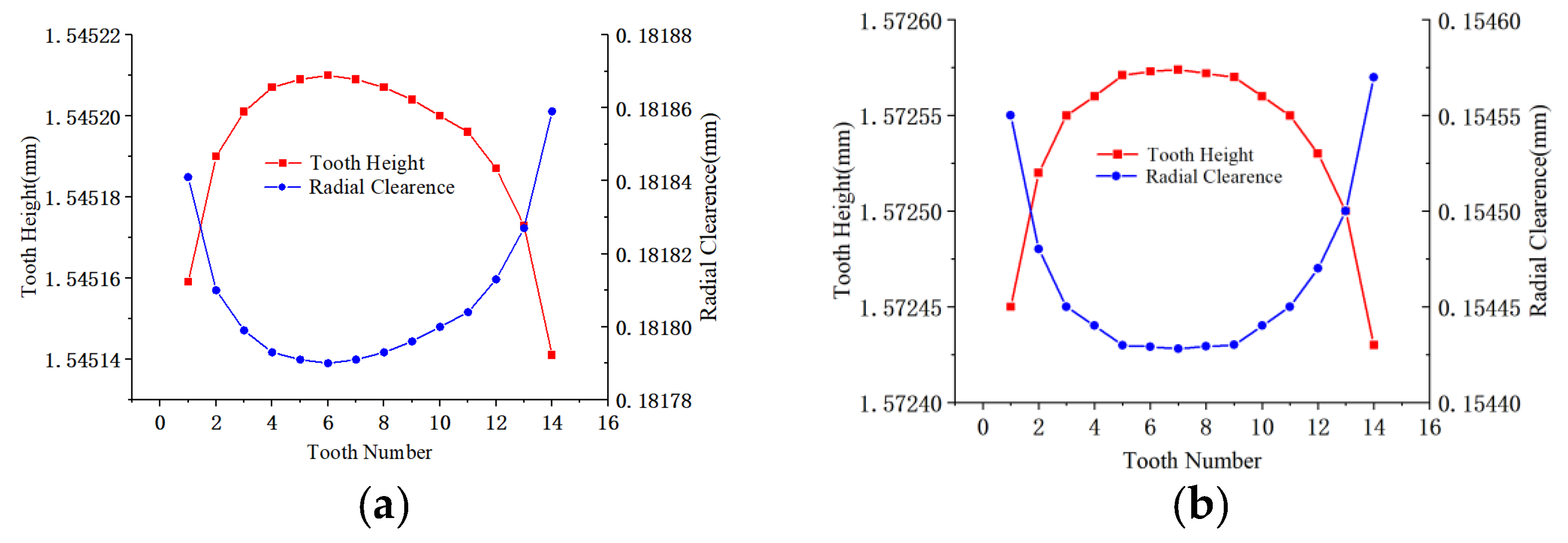
The following Figure 7 shows the changes in the height of the seal teeth and the seal clearance when the water temperature is 50 °C and 86 °C. It can be seen from the figure that the height of the seal teeth increases first and then decreases in the flow direction, while the seal clearance first decreases and then increases.
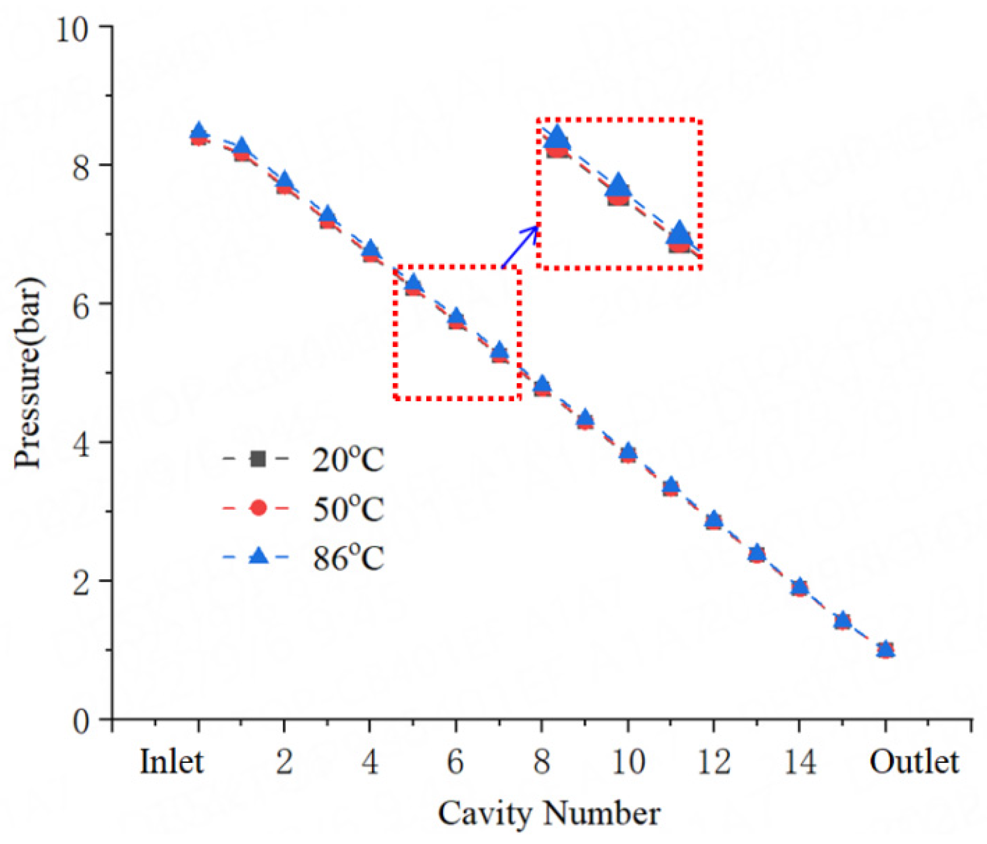
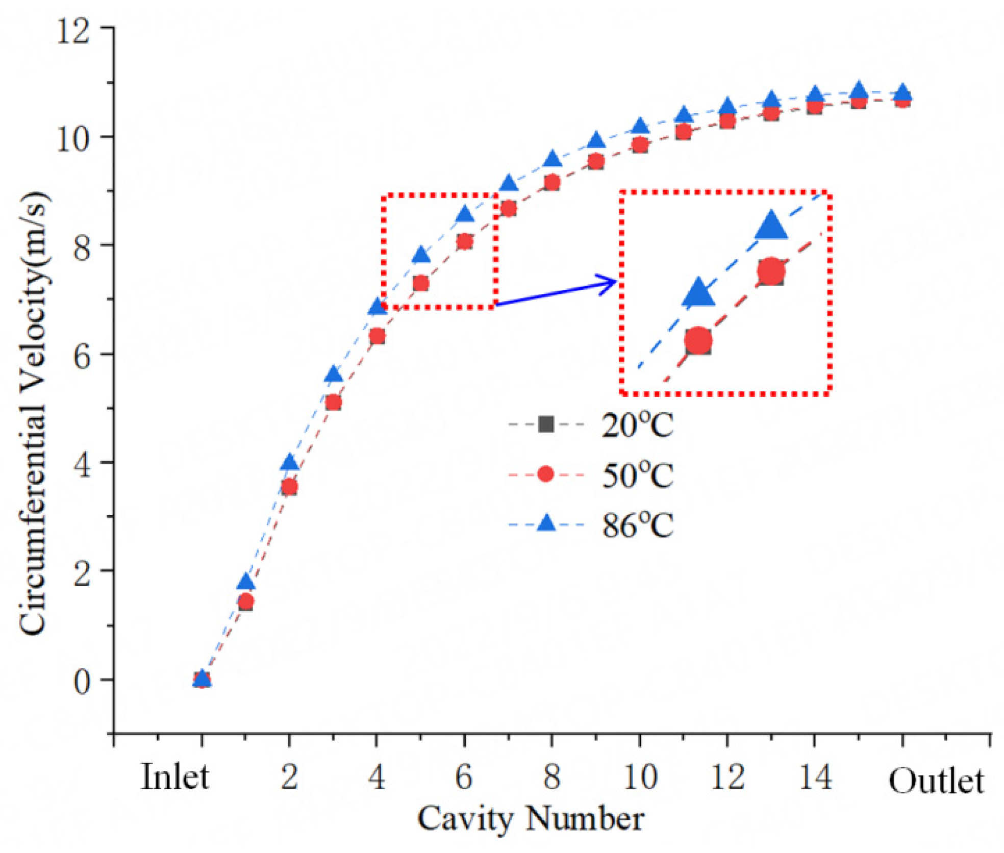
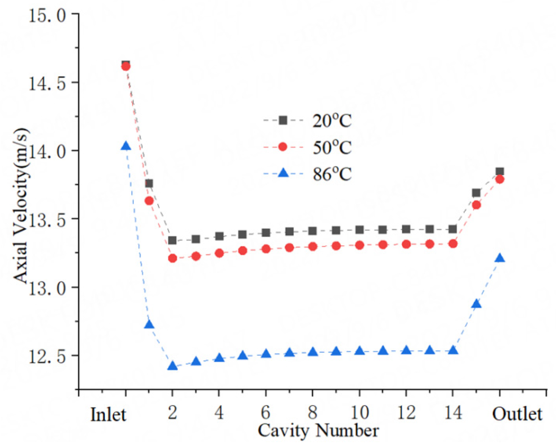
Figure 8 shows the Pressure distribution in the seal cavities. When the temperature increases, the pressure in the seal cavity does not change much. It only slightly increases, which may be due to the reduction of the seal clearance. Figure 9 gives the circumferential velocity in the seal cavities. As the temperature increases, the height of the seal teeth increases and the viscosity of the water decreases. It can be seen from the figure that when the water temperature is 86 °C, the circumferential flow rate of the water increases, which can be explained by the fact that the effect of the seal clearance change is greater than the change in the viscosity of the water. Figure 10 illustrates the circumferential velocity in the seal cavities. For the axial velocity in the seal cavity, when the temperature increases, the smaller the axial velocity, the smaller the seal leakage flow rate, which is mainly due to the reduction of the seal clearance.

3. Dynamic Coefficients Calculation Verification

3.1. Computational Method

When rotor is whirling with a small motion, which is around its equilibrium position, the force, which is induced by the fluid, can be written by the following equation:
[ F x F y ] = [ K k k K ] [ X Y ] + [ C c c C ] [ X Y ] + [ M m m M ] [ X Y ]
where K = Kxx = Kyy,k = Kxy = −Kyx,C = Cxx = Cyy,c = Cxy = −Cxy,M = Mxx = Myy,m = Mxy = −Myx.
Fx and Fy are the fluid-induced forces in x and y directions, K and k are the direct stiffness and cross-coupling stiffness coefficient, C and c are the direct damping and cross-coupling damping coefficient, M and m are direct virtual mass and cross-coupling virtual mass. X and Y are the relative small displacement. Kij,Cij and Mij are the dynamic coefficient of different directions.
Equation (1) can be stated in the frequency domain:
[ F x ( Ω ) F y ( Ω ) ] = [ H x x ( Ω ) H x y ( Ω ) H y x ( Ω ) H y y ( Ω ) ] [ D x ( Ω ) D y ( Ω ) ]
where Ω is the whirling speed, D i ( Ω ) is the rotor motion in i direction, the H i j ( Ω ) is the complex force impedances that can be expressed as follows:
H x x = H y y = ( F x ) D x ( F y ) D y D x D x + D y D y H x y = H y x = ( F x ) D y ( F y ) D x D y D y + D x D x
The relationship between the force impedances and dynamic coefficients can be stated:
H i j = K i j Ω 2 M i j + j ( Ω C i j )
where i,j represent one of x,y.
The real part and imaginary part of the force impedance coefficient can be expressed as follows:
Re ( H i j ) = K i j Ω 2 M i j
Im ( H i j ) = Ω C i j
From Formulas (5) and (6), the frequency-independent dynamic coefficients can be obtained by fitting the real part and imaginary part at multiple frequencies.
We assume that the rotor is whirling around its centered position, the tangential force and the radial force can be written:
F t / e = K x y + Ω 2 M x y + Ω C x x = Re ( H x y ) + Im ( H x x )
F r / e = K x x Ω 2 M x x + Ω C x y = Re ( H x x ) + Im ( H x y )
Effective stiffness and effective damping are often needed to analyze the overall stability characteristics. They are expressed:
K eff = F r / e = Re ( H x x ) + Im ( H x y )
C eff = ( F t / e ) / Ω = ( Re ( H x y ) + Im ( H x x ) ) / Ω
From this formula we notice that the frequency-dependent effective stiffness K eff is the combination of K, M, c, the frequency-dependent effective damping C eff is the combination of k, m, C.
The user-defined function (User-Defined Function) DEFINE_CG_MOTION is used to realize the whirling motion of the rotor.
The whirling motion displacement can be expressed:
x ( t ) = a i = 1 N cos ( Ω t t ) y ( t ) = b i = 1 N sin ( Ω t t )
The whirling motion velocity equation can be stated as.
x ( t ) = a Ω i i = 1 N sin ( Ω i t ) y ( t ) = b Ω i i = 1 N cos ( Ω i t )
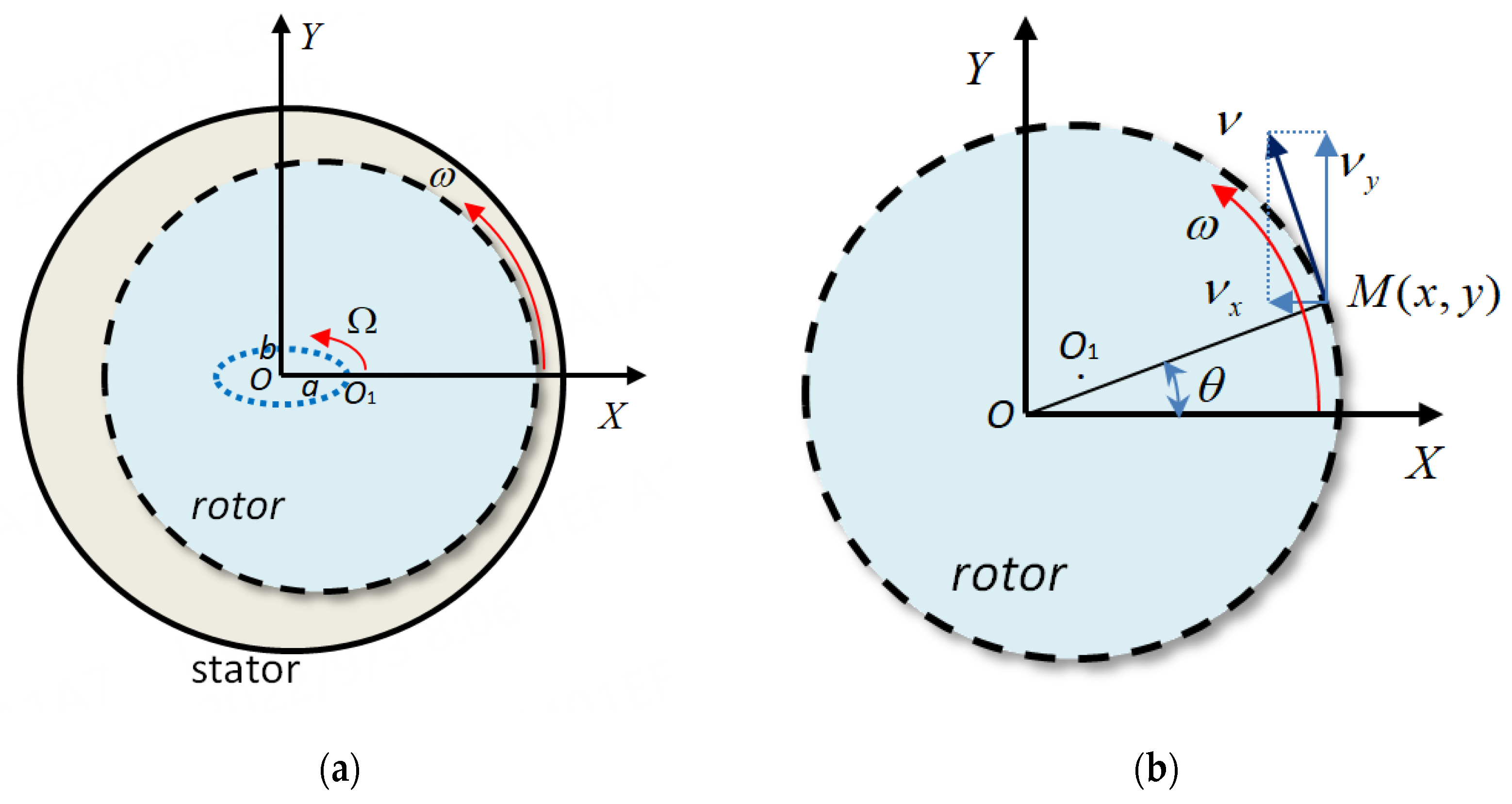
The a, b are the symbols of the major axis and minor axis of the elliptic orbit of the whirling model, respectively. The whirling motion model can be seen in Figure 11a.
The follow-up coordinate system is established through the DEFINE_PROFILE control macro to realize the rotation of the rotor at any position.
Suppose there is an any point M(x,y) on the surface of the eccentric rotor, and its distance from the coordinate origin is
r = x 2 + y 2
At a certain time t, the angle deviating from the y axis is
θ = arctan 2 ( x , y )
The velocity of point M is often decomposed into components along the coordinate axis x and y direction,
ν x = ω r sin θ ν y = ω r cos θ
If   x   >   0 ,   ν y = ν y
If   y   >   0 ,   ν x = ν x
The rotor rotating motion model can be seen in Figure 11b.

3.2. Verification

In order to verify the accuracy of the CFD calculation, this case uses the 46 °C ISOVG2 oil as the liquid medium, the inlet pressure is 5.14 bar, the outlet pressure is 1.0 bar, the rotational speed is 6000 r/min, and the inlet preswirl ratio is 0.2.
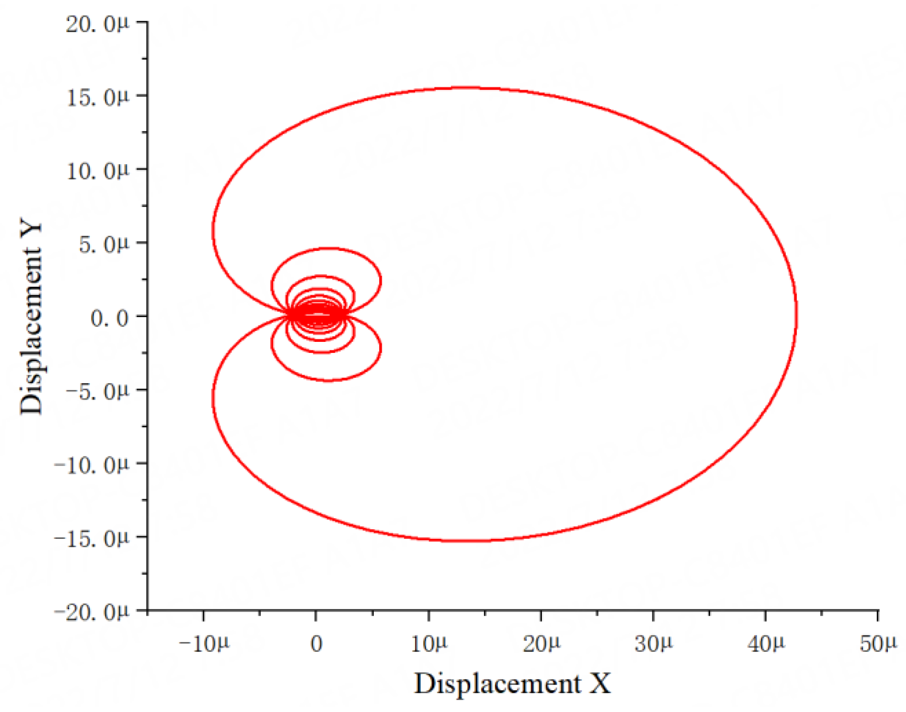
Figure 12 gives the example of the whirling orbit (X direction), this is the multiple frequencies elliptical whirling orbit of the rotor. According to Formula (17), the elliptical whirling frequencies we used in this paper are 20, 40, 60 … 200 Hz. It includes 10 frequencies. To satisfy the theory of small displacement disturbance, we assume that a = 0.02 cr, b = 0.01 cr, where a, b are the motion amplitude, cr is the seal radial clearance.
The time-varying rotor motion in X and Y directions is monitored. Figure 13a shows the example of the rotor motion in the time-domain. Through FFT transformation, we obtained the frequency-varying rotor motion in X and Y directions, which can be seen in Figure 13b. Similarly, the response force in the time-domain and in the frequency-domain can also be obtained, which can be seen in Figure 14a,b.
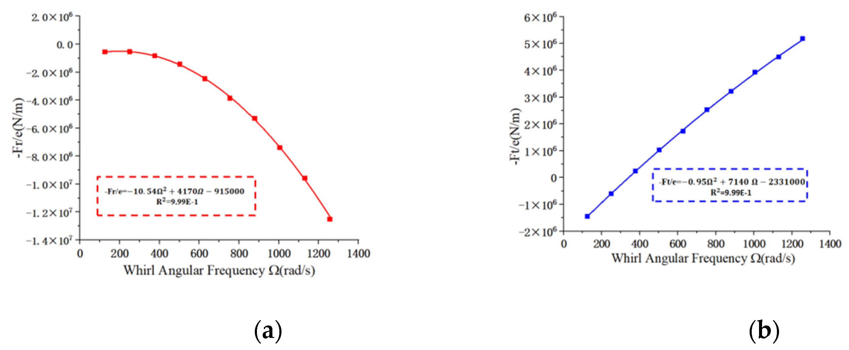
When calculating the dynamic coefficients, different whirling frequencies need to be applied to calculate the tangential force and the radial force. According to Formulas (13) and (14), the dynamic coefficients can be obtained by data fitting. Figure 15 shows the quadratic regression fitting curve of radial fluid force and tangential fluid force versus Ω . According to Formulas (13) and (14), the slopes of the curves are the direct damping coefficients (C), and cross-coupling damping coefficients (c), and the intercepts of the curves are the direct stiffness coefficients (K) and cross-coupling stiffness coefficients (k).
From Table 6, we can see a modest calculation error compared with the test, Li et al. attribute this outcome to the asymmetrical structure stiffness and damping in two directions of the test rig [22]. In general, the present method is a reasonable way to calculate the rotordynamic coefficients.

4. Calculation Model Results and Discussion

4.1. Test Results

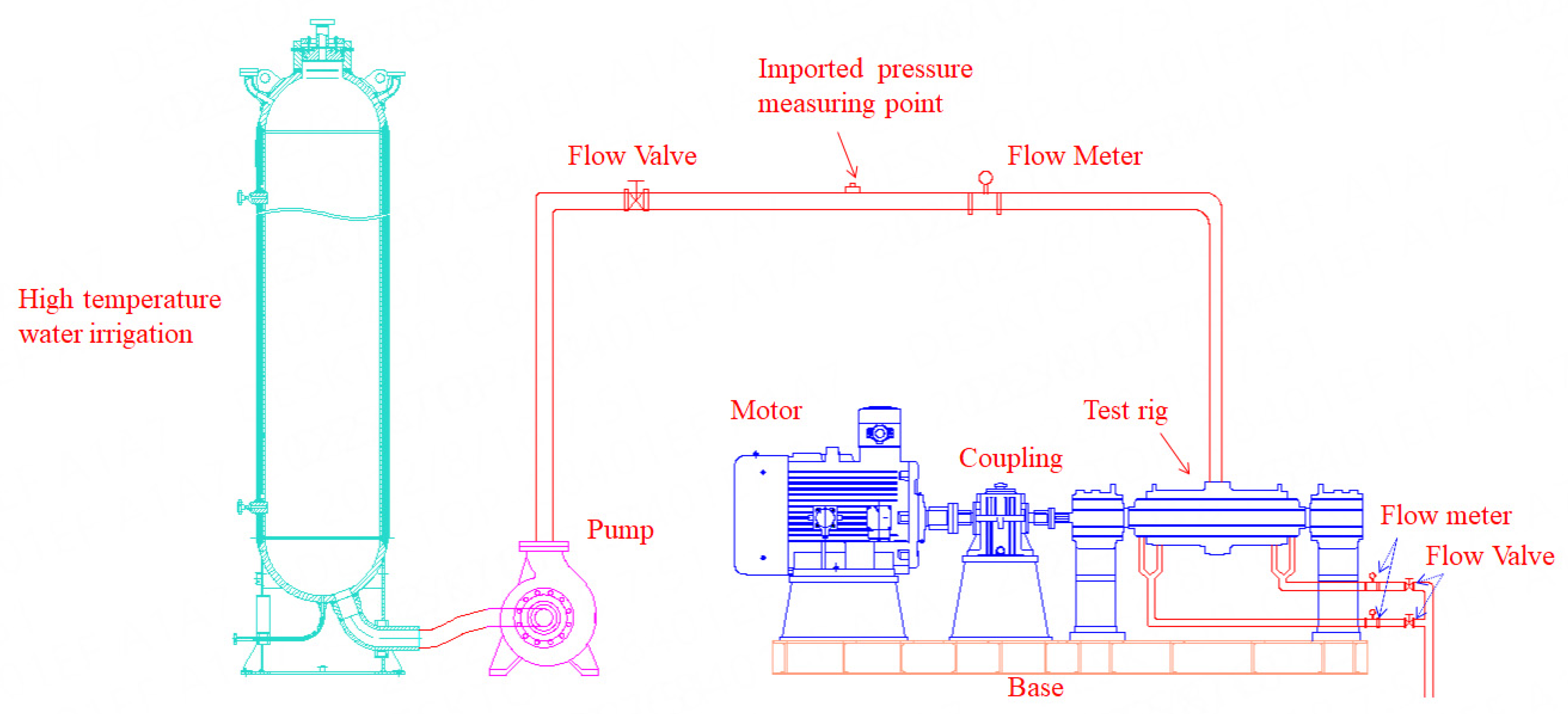
A seal test rig including high-temperature water irrigation is used for the experiments to prove the reliability of numerical calculation. In the experiments, the high-temperature water irrigation can supply water at different temperatures. The test rig is shown in Figure 16, the electromagnetic flowmeter is used to test the leakage flow rate, and the power analyzer is used to test the drag power loss. Figure 17 gives the test schematic. The high-temperature water irrigation volume is 46 m3, with an electrical heater that can heat water. After the water has been heated, the high-temperature water enters the centrifugal pump. The centrifugal pump is pressurized to provide high-temperature water to the test device. Thus, the water has a certain pressure and temperature before it enters the seal test rig. The temperature and pressure of water are changed by high-temperature irrigation and centrifugal pump, respectively. The seal test rig is used to test the leakage flow rate and drag power loss.
Due to vibration and other reasons during the test, there will be slight fluctuations in the measured values. During the measurement, operations including the rotational speed increase and decrease, the pressure drop increase and decrease were performed. The average test value is used after the operating condition is stable.
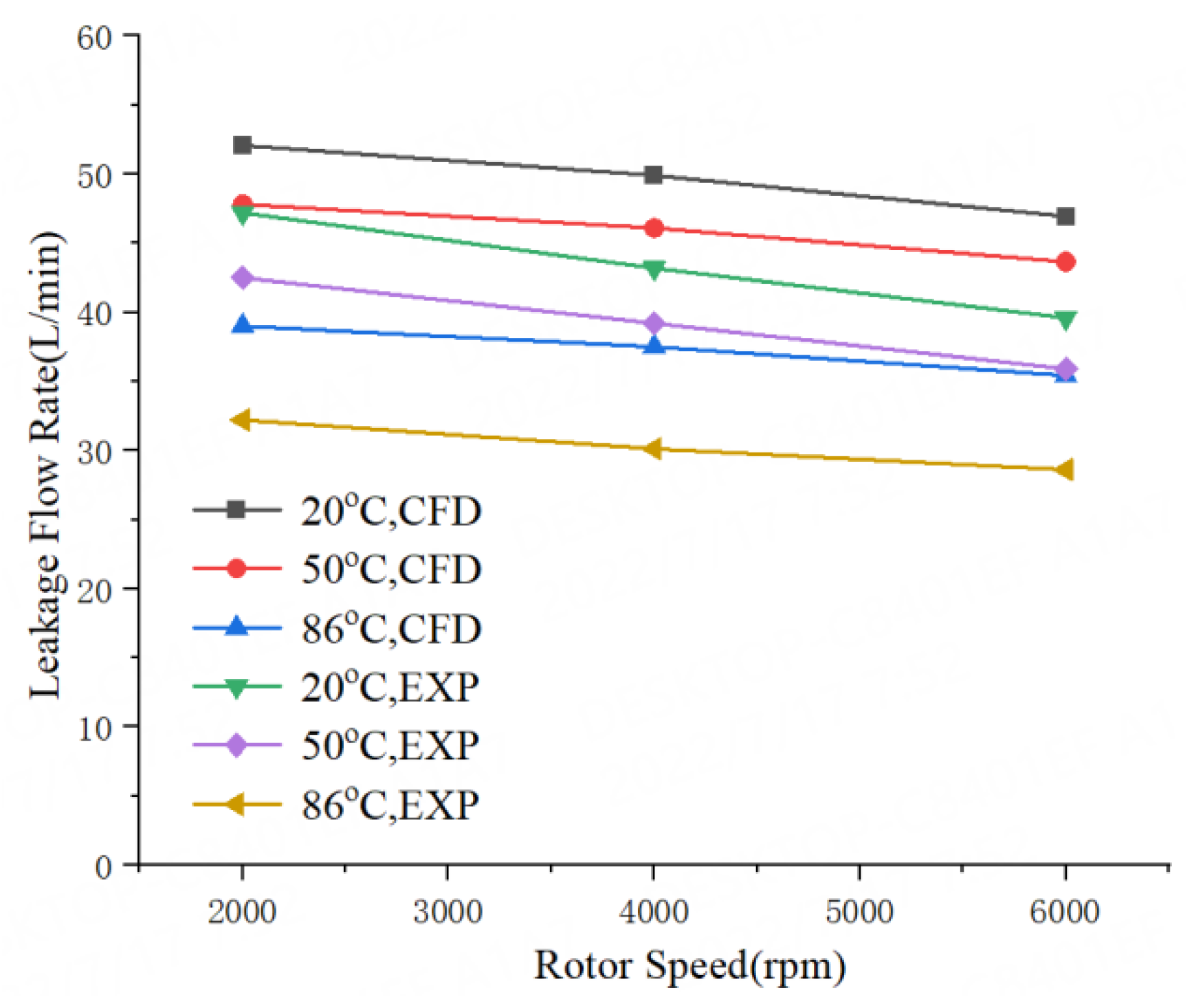
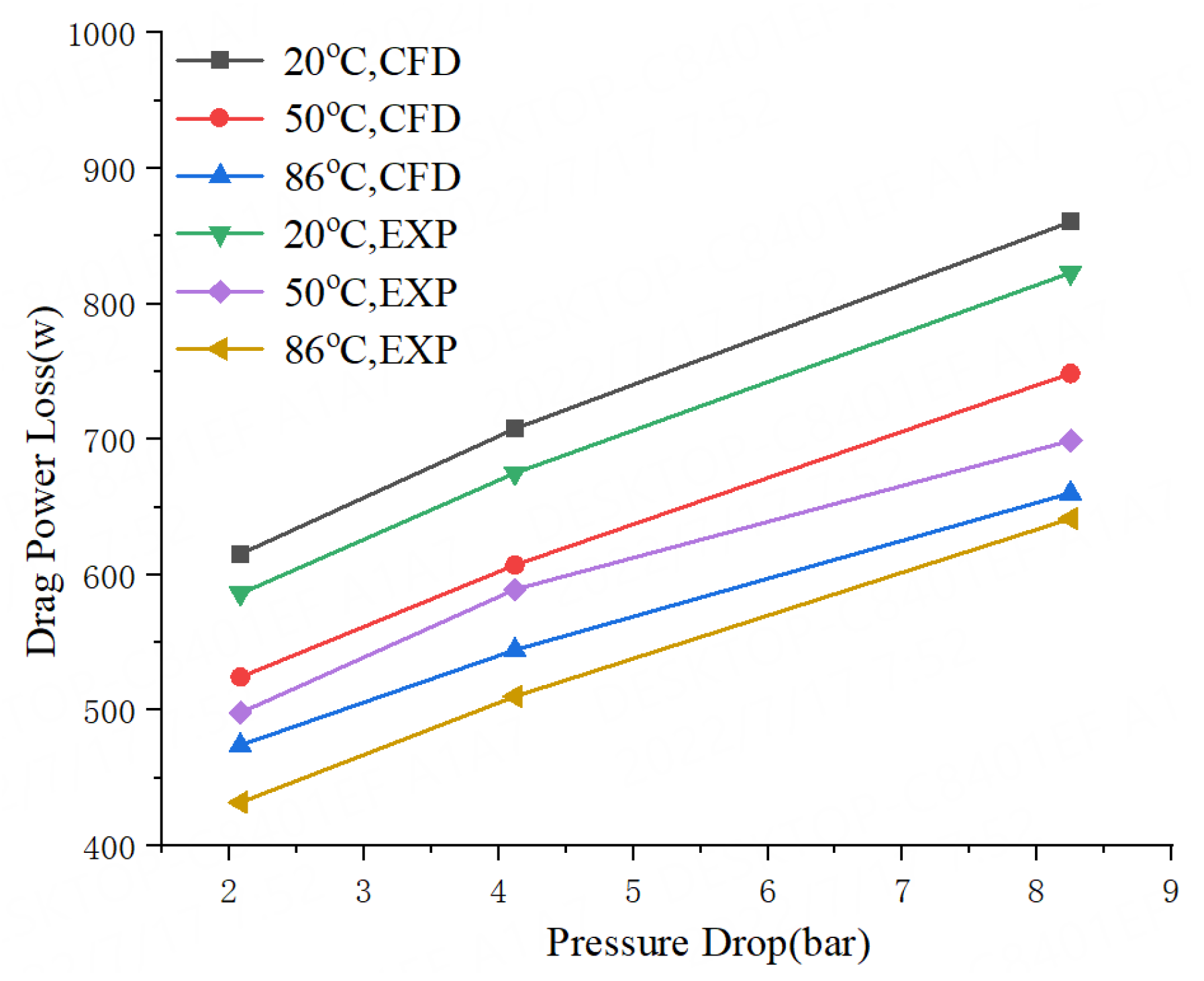
Figure 18 and Figure 19 give the comparison between the test results and the calculation results of the leakage flow rate and drag power loss. It can be seen that the test results of the leakage flow rate and drag power loss are basically the same as the calculation results, and the relative deviations are small, the maximum deviation is about 21.5%. The results show that the model is correct and can be used for dynamic calculation of high-temperature liquid seals.

4.2. Effects of Pressure Drop

In actual engineering applications, the pressure drop and rotational speed are the two important operation factors for the pump. To know the influence of pressure drops on the rotordynamic characteristics, CFD solutions was used at pressure drops of 2.08, 4.12, and 8.25 bar for the seals with three different temperature water (20 °C, 50 °C and 86 °C). Due to the increase of temperature, the height of the seal teeth will increase, and the seal clearance will decrease. Meanwhile, the physical property of the water will also change, all of these will affect the rotordynamic coefficients of the seal.
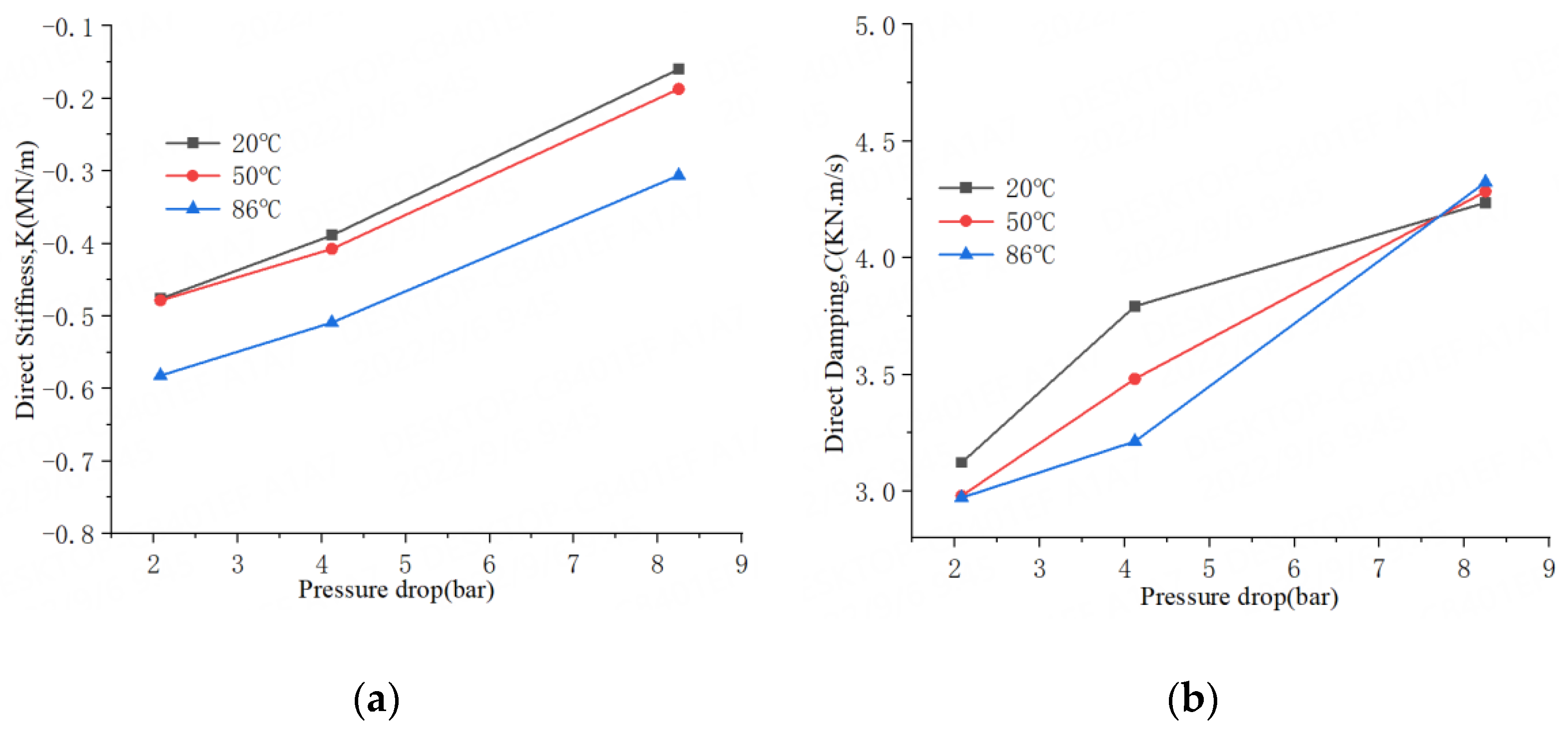
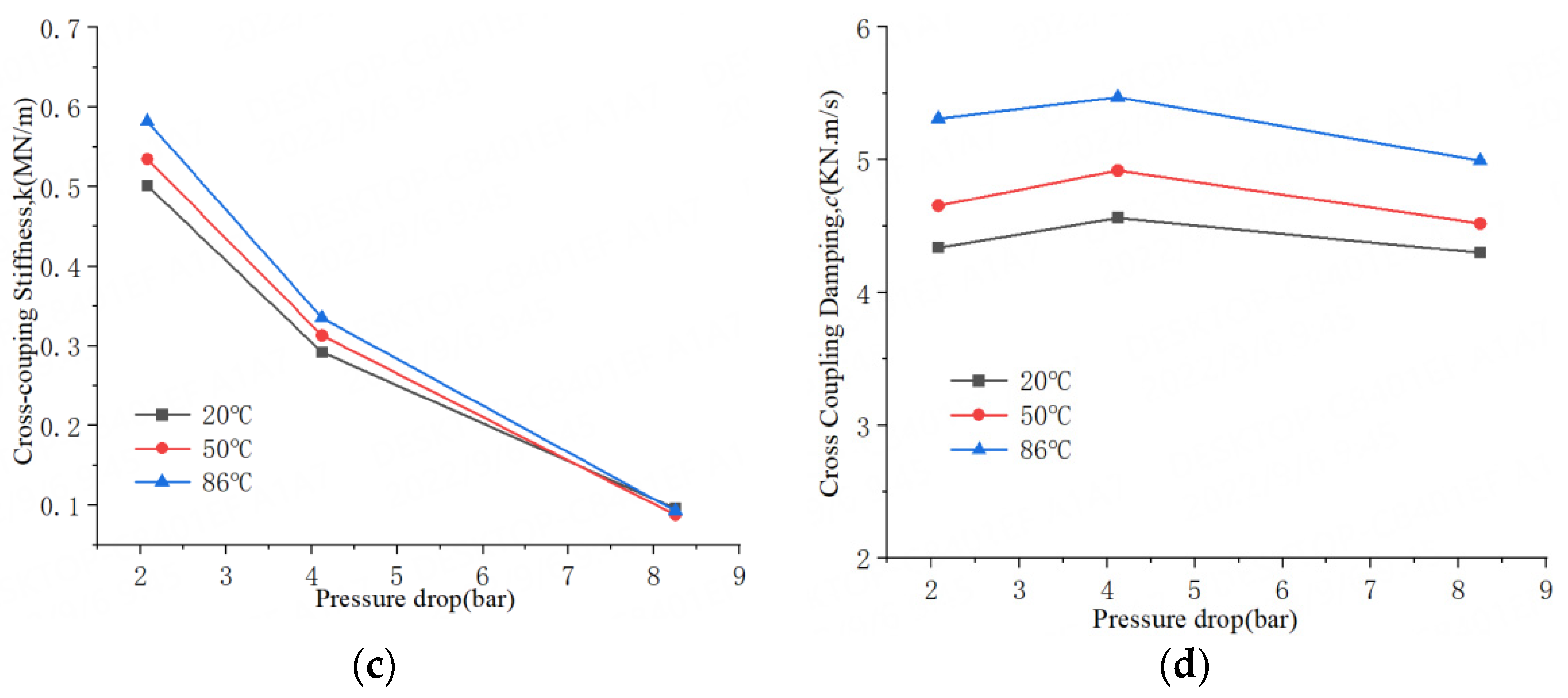
Figure 20 gives the plots of frequency-independent rotordynamic coefficients versus pressure drop for water liquid seal at three different temperatures (n = 4000 r/min). For all three temperatures, the direct stiffness K is negative value, which can be seen in Figure 20a. It shows an obvious increase with the increase of pressure drops, this can be explained by the fact that when the pressure drop increases, the Lomakin effect increases. The K for 86 °C water liquid seal is larger than the other two temperature seals (−22–−91% for 20 °C seal, −21–−63% for 50 °C seal). The cross-coupling stiffness k of three temperature seals is positive, seen in Figure 20c, and they show a decrease with the increase of pressure drops (−0.40 MN/m for 20 °C seal, −0.45 MN/m for 50 °C sea,l and −0.49 MN/m for 86 °C seal from 2.08 to 8.25 bar).
The direct damping C for three temperature seals, which can be seen in Figure 20b, shows an increase with the increase of pressure drops (35% for 20 °C seal, 44% for 50 °C seal, and 45% for 86 °C seal from 2.08 to 8.25 bar). Generally, the C for 20 °C water liquid seal is slightly larger than the other two temperature seals (−1–4% for 50 °C seal, -2–5% for 86 °C seal).
Figure 20d shows the cross-coupling damping c for three temperature seals. The value of c is positive and shows an increase, first, with the increase of pressure drops (7% for 20 °C seal, 8% for 50 °C seal and 5% for 86 °C seal from 2.08 to 4.12 bar) and then, it shows a decreasing trend (−14% for 20 °C seal, −11% for 50 °C seal, and −10% for 86 °C seal from 4.12 to 8.25 bar). The c of 86 °C water liquid seal is larger than the other two temperature seals.
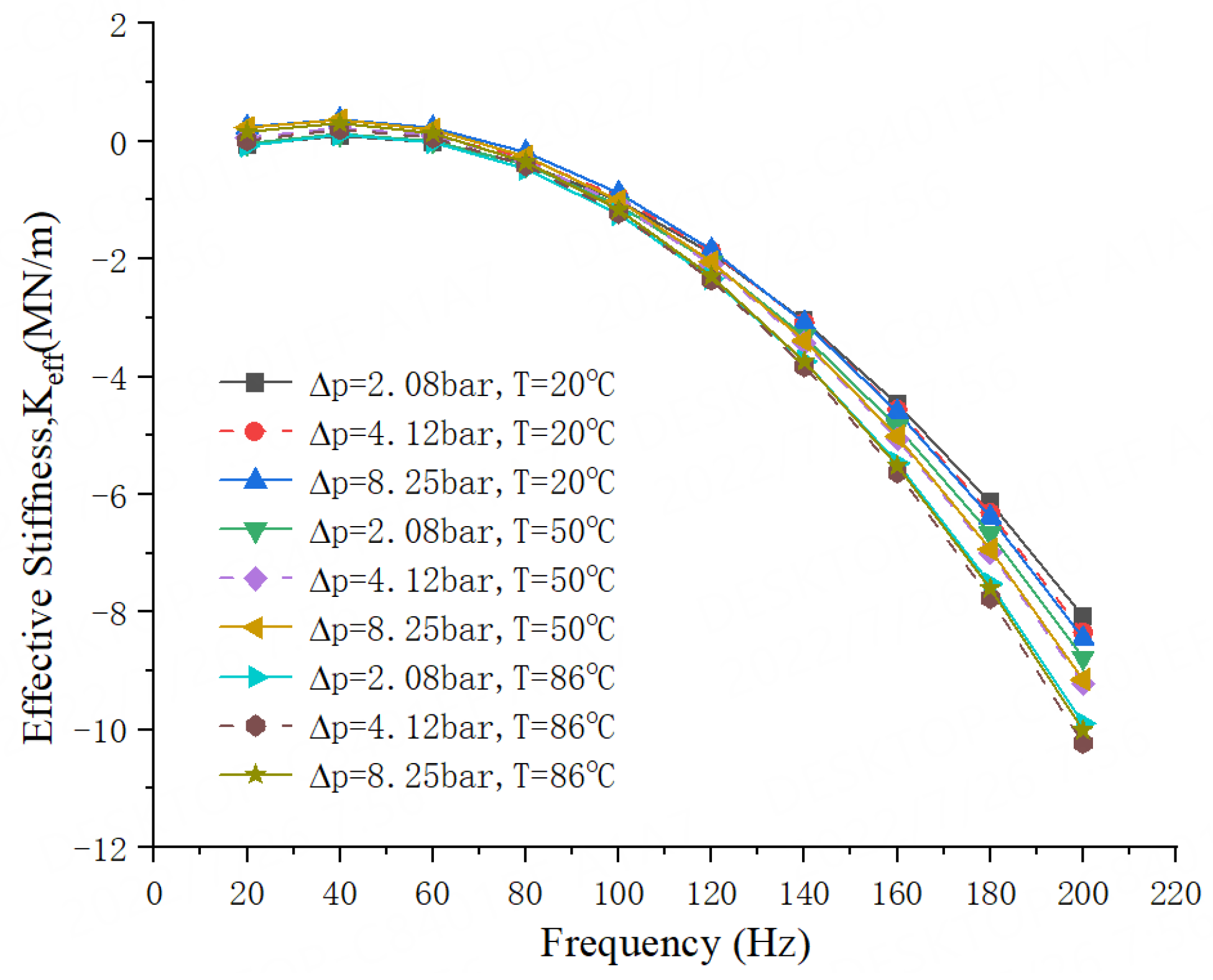
The frequency-dependent effective stiffness coefficient Keff is related to the K, M, and c. It can be seen from Figure 21 that three temperature seals have small positive Keff at a lower frequency range and show a parabolic decay trend. With the increase of pressure drop, the Keff of three temperature seals has a slightly increase. It can also be seen that temperature has a larger impact on the Keff, especially on the high whirl frequency, for example, the Keff for 20 °C water liquid seal is larger than the other two temperature seals when Ω = 160 Hz. It is noticeable that the 86 °C water liquid seal has the largest K (negative value), and the Keff for 86 °C water liquid seal almost smaller than the other two seals. this is due to the combined influence of the K, M, and c. The Keff is a proper metric to evaluate the overall seal stiffness capability.
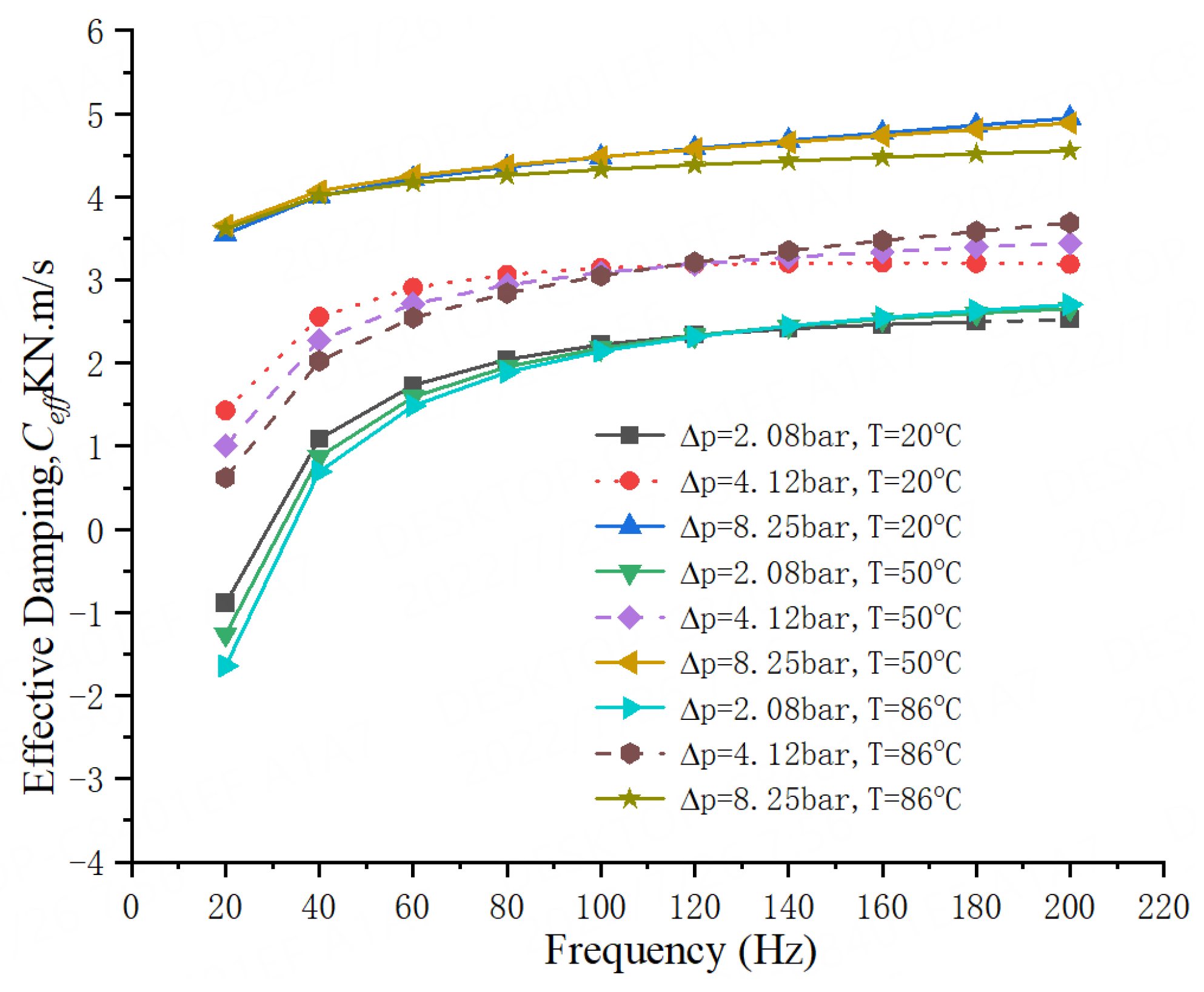
Figure 22 shows the plot of the frequency-Dependent effective damping coefficient Ceff which is affected by the C, k, and m. Three temperature seals possess the positive Ceff in the whole whirling frequency range except for the condition of low whirl frequency (Ω = 20 Hz, Δp = 2.08 bar). The Ceff for seals has an obvious increase with the increase of pressure drop, this is mainly because of the increase of direct damping coefficient and the decrease of cross-coupling stiffness. It is noticeable that the Ceff for 20 °C water liquid seal is slightly larger (1–9%) than the other two seals at the lower frequencies (<100 Hz).

4.3. Effects of Rotational Speed

To investigate the influence of rotational speed on the rotordynamic characteristics, CFD solutions were performed at a rotational speed of 2000, 4000, and 6000 r/min for the seals with three different temperature water (20 °C, 50 °C, and 86 °C).
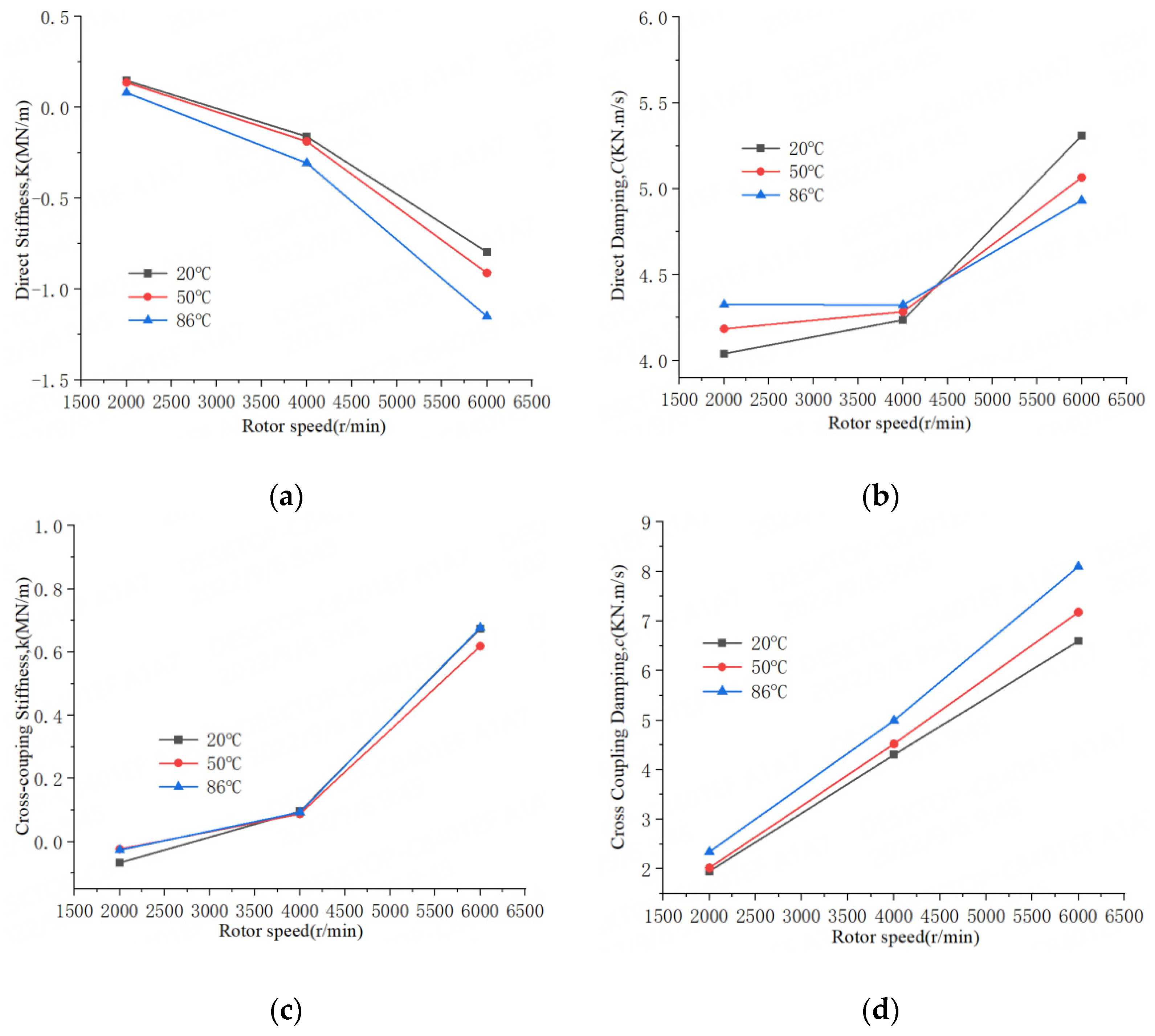
Figure 23 gives the plots of frequency-independent rotordynamic coefficients versus rotational speed for water liquid seal at three different temperatures (Δp = 8.25 bar). Figure 23a gives the direct stiffness K for three temperature seals. It shows a decrease with the increase of rotational speed. It also means an increase in the absolute value of its negative K. This is because with the increase of rotational speed, the fluid bearing effect will increase. The fluid-induced radial force, which is consistent with the eccentric direction of the rotor, will increase [3]. The K for 20 °C water liquid seal is generally larger than the other two temperature seals (7–14% for 50 °C seal, 30–83% for 86 °C seal).
The cross-coupling stiffness k shows an increase with the increase of rotational speed (0.74 MN/m for 20 °C seal, 0.64 MN/m for 50 °C seal, and 0.70 MN/m for 86 °C seal from 2000 to 6000 r/min), and it can be seen in Figure 23c. This is because, with the increase of the rotational speed, the circumferential flow in the seal cavity and clearance will increase, which will cause the increase of cross-coupled stiffness. Generally speaking, the 20 °C water has the highest viscosity but also has the largest seal clearance. The 86 °C water has a lowest viscosity, but also has the smallest seal clearance. From Figure 8, we can see that the circumferential flow velocity of 86 °C water is larger than the other two, mainly because of its small seal clearance. The circumferential velocity has been shown to be the main reason for the instability of the seal force [3]. This means the 86 °C seal has relatively lower stability compared to the other two.
Figure 23b,d illustrates the direct damping C and The cross-coupling damping c, respectively. The direct damping C for three temperature seals is positive value and shows an increase with the increase of rotational speed (21% for 20 °C seal, 21% for 50 °C seal, and 14% for 86 °C seal from 2000 to 6000 r/min). The cross-coupling damping c for three temperature seals shows an increase with the increase of rotational speed (238% for 20 °C seal, 255% for 50 °C seal, and 245% for 86 °C seal from 2000 to 6000 r/min). The c of 86 °C water liquid seal is larger (10–16%) than the other two temperature seals.
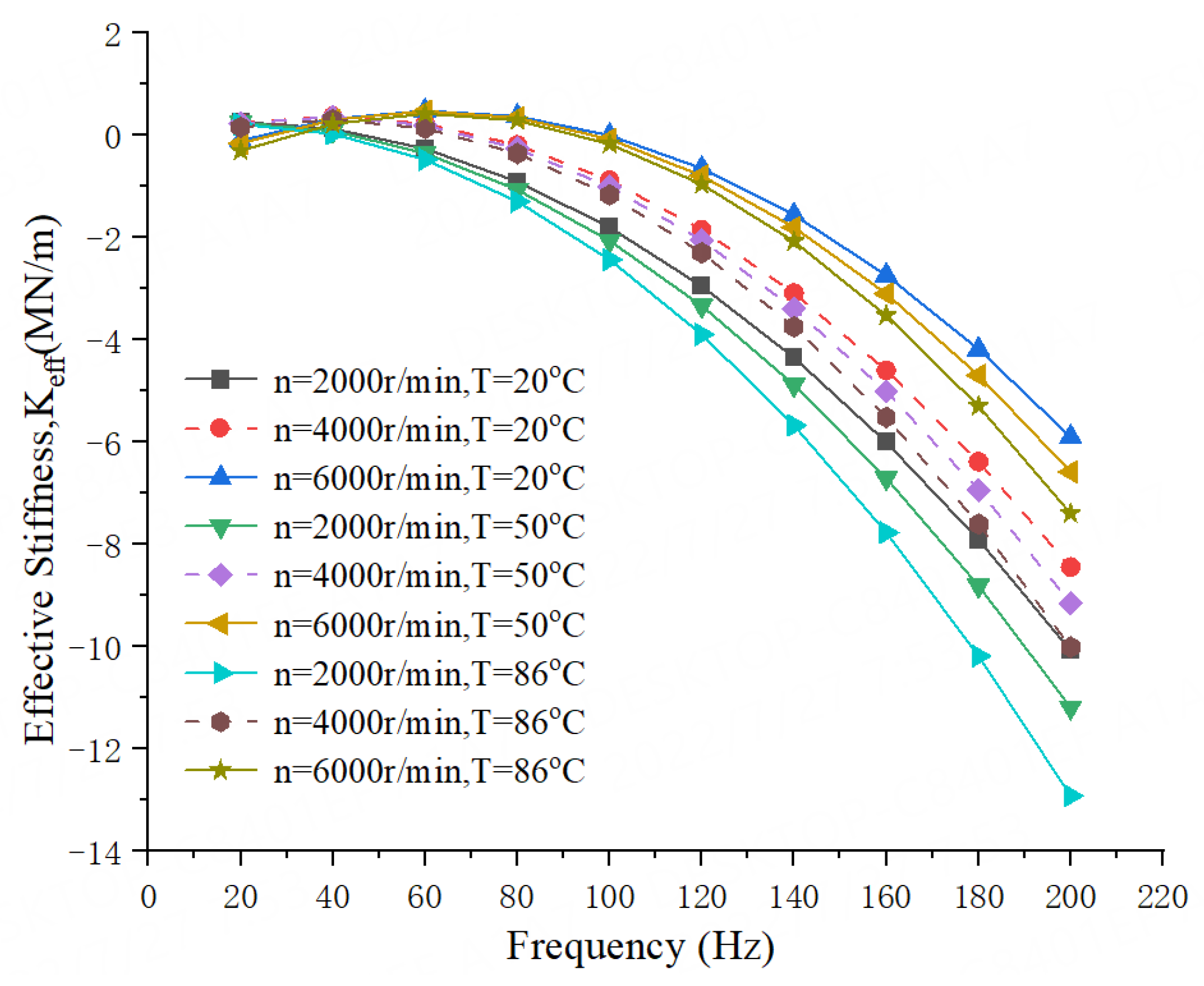
The frequency-dependent effective stiffness coefficient Keff can be seen from Figure 24 that three temperature seals show a parabolic trend, and the effect of the rotational speed is obvious in the whole frequency range. With the increase of rotational speed, the Keff increases. It can also be seen that with the increase of temperature, the Keff decreases. Therefore, the Keff for 20 °C water seal possesses a better stiffness capability than the other two temperature seals at the same operational condition [30].
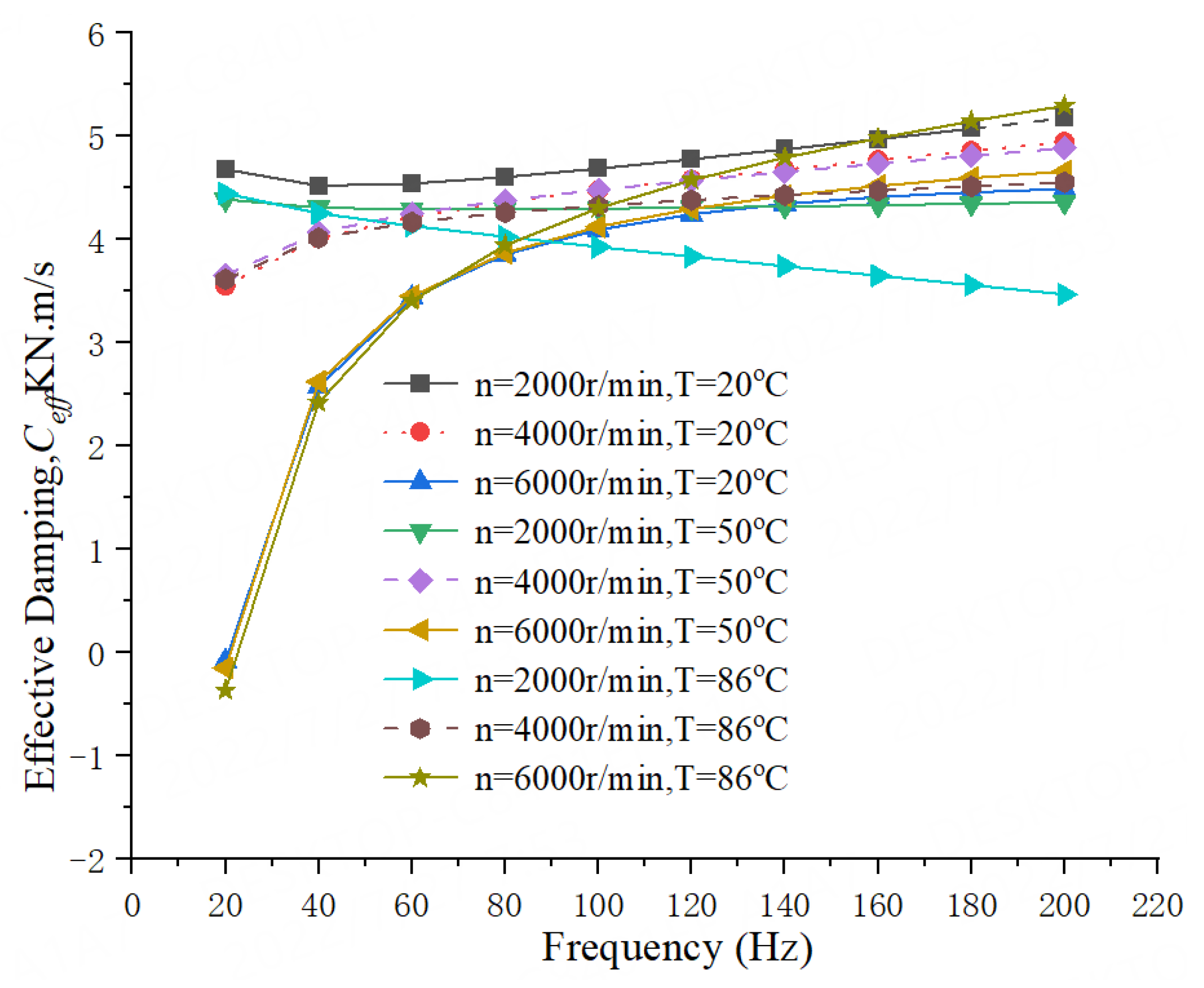
Figure 25 shows the plot of the frequency-dependent effective damping coefficient Ceff. Three temperature seals have positive Ceff in the whole whirling frequency for the 2000 and 4000 r/min cases. The Ceff for 20 °C water seal is larger than the other two temperature seals. As the rotational speed increases, Ceff for three temperature seals shows an obvious decrease and changes to negative value at Ω = 20 Hz for 6000 r/min. Considering that the rotational speed of most centrifugal pumps is about 4000 r/min, the 20 °C water seal is relatively more stable than the other two temperature seals due to its larger Ceff.
In this part, we found that the temperature has an influence on the leakage flow rate and drag power loss of water liquid seal at different temperatures by comparing the CFD calculations and experimental results. There may be a certain error between calculation and experiment due to the influence of machining accuracy and assembly accuracy.
In terms of rotordynamics, we analyzed the effect of different water temperatures on the seal dynamics. As a part of the centrifugal pump rotor system, the seal plays an important role. In the actual application of the centrifugal pump, we found that the high-temperature pump has more failures than the normal temperature pump, and there are more instability problems in the rotor system. From the research of this article, some cases have also been verified, with the temperature of the medium in the centrifugal pump increases, the instability of the rotor system increases too.

5. Conclusions

In this paper, in order to understand the characteristics of liquid seal at different temperatures, the experiment was carried out to test the leakage flow rate and drag power loss of water liquid seal at three different temperatures (20 °C, 50 °C, 86 °C). The frequency-independent rotordynamic coefficients (K, k, C, c) and frequency-dependent rotordynamic coefficients (Keff, Ceff) were also analyzed by the transient CFD-based method. The effects of different pressure drops (2.08, 4.12, and 8.25 bar) and different rotational speeds (2000, 4000, and 6000 r/min) are considered in the model. From this study, the following conclusions are obtained:
  • With the increase of water temperature, the radial deformation of the seal teeth increases, and the seal clearance decreases. The leakage flow rate of water liquid seal decreases, and the power drag loss decreases too. The leakage flow rate of 86 °C water liquid seal is 25% smaller than 20 °C water liquid seal. The drag power loss of 86 °C water liquid seal is 22% smaller than 20 °C water liquid seal. The leakage flow rate decreases with the increase of the rotor speed, and the drag power loss increases with the increase of the pressure drop. This means the 86 °C water seal has a better sealing capacity.
  • For all operation conditions, the 20 °C water liquid seal has a relatively large direct stiffness coefficient K, followed by 50 °C water liquid seal. With the increase of water temperature, the direct stiffness coefficient decreases, and the effective stiffness coefficient Keff for 20 °C water seal possesses a better stiffness capability than the other two temperature seals.
  • For all operation conditions, compared to the 50 °C and 86 °C water liquid seal, the 20 °C water liquid seal has a larger effective damping coefficient Ceff in the whole whirling frequency range, it is more stable for the rotor system.

Author Contributions

Conceptualization, P.C. and T.W.; methodology, Z.X.; software, W.M.; validation, P.C., T.W. and W.M.; formal analysis, P.C.; investigation, P.C.; resources, G.Y.; data curation, T.W.; writing—original draft preparation, P.C.; writing—review and editing, Z.X.; visualization, W.M.; supervision, Z.X.; project administration, T.W.; funding acquisition, W.M. All authors have read and agreed to the published version of the manuscript.

Funding

This work is supported by National Key Research and Development Program of China (NO: 2020YFC1512403), Key projects of technological innovation and application development of Chongqing, China (Grant NO. cstc2020jscx-msxm0411) and Major scientific and technological achievement transformation project of Heilongjiang Province, China (CG20A006).

Institutional Review Board Statement

Not applicable.

Informed Consent Statement

Not applicable.

Data Availability Statement

Not applicable.

Conflicts of Interest

The authors declare no conflict of interest.

Nomenclature

KeffEffective stiffness (N/m)
KxxDirect stiffness in x direction (N/m)
KxyCross coupling stiffness in x direction (N/m)
KyyDirect stiffness in y direction (N/m)
KyxCross coupling stiffness in y direction (N/m)
mCross coupling virtual-mass (kg)
MDirect virtual-mass (kg)
MxxDirect virtual-mass in x direction (kg)
MxyCross coupling virtual-mass in x direction (kg)
MyyDirect virtual-mass in y direction (kg)
MyxCross coupling virtual-mass in y direction (kg)
CeffEffective damping (Ns/m)
CxxDirect damping in x direction (Ns/m)
CxyCross coupling damping in x direction (Ns/m)
CyyDirect damping in y direction (Ns/m)
CyxCross coupling damping in y direction (N s/m)
Dxx:Rotor motion in x direction for x direction excitation (m)
DxyRotor motion in y direction for x direction excitation (m)
DyyRotor motion in y direction for y direction excitation (m)
DyxRotor motion in x direction for y direction excitation (m)
FrResponse force in radial direction (N)
FtResponse force in tangential direction (N)
FxxResponse force in x direction for x direction excitation (N)
FxyResponse force in y direction for x direction excitation (N)
FyyResponse force in y direction for y direction excitation (N)
FyxResponse force in x direction for y direction excitation (N)
HxxDirect force impedance in x direction (N/m)
HxyCross coupling force impedance in x direction (N/m)
HyyDirect force impedance in y direction (N/m)
HyxCross coupling force impedance in y direction (N/m)
nRotational speed (r/min)

References

  1. Vance, J.M. Machinery Vibration and Rotordynamics; Wiley: New York, NY, USA, 2010; pp. 271–278. [Google Scholar]
  2. Childs, D.W.; Vance, J.M. Annular Seals and the Rotordynamics of Compressors and Turbines. In Proceedings of the 26th Turbomachinery Symposium, Houston, TX, USA, 14–18 September 1997; pp. 201–220. [Google Scholar]
  3. Childs, D.W. Turbomachinery Rotordynamics with Case Studies; Minter Spring Publishing: Wellborn, TX, USA, 2013. [Google Scholar]
  4. Xie, Z.; Wang, X.; Zhu, W. Theoretical and experimental exploration into the fluid structure coupling dynamic behaviors towards water-lubricated bearing with axial asymmetric grooves. Mech. Syst. Signal Process. 2022, 168, 108624. [Google Scholar] [CrossRef]
  5. Xie, Z.; Zhu, W. Theoretical and experimental exploration on the micro asperity contact load ratios and lubrication regimes transition for water-lubricated stern tube bearing. Tribol. Int. 2021, 164, 107105. [Google Scholar] [CrossRef]
  6. Xie, Z.; Zhu, W. An investigation on the lubrication characteristics of floating ring bearing with consideration of multi-coupling factors. Mech. Syst. Signal Process. 2022, 162, 108086. [Google Scholar] [CrossRef]
  7. Xie, Z.; Zhang, Y.; Zhou, J.; Zhu, W. Theoretical and experimental research on the micro interface lubrication regime of water lubricated bearing. Mech. Syst. Signal Process. 2021, 151, 107422. [Google Scholar] [CrossRef]
  8. Xie, Z.; Shen, N.; Zhu, W.; Tian, W.; Hao, L. Theoretical and experimental investigation on the influences of misalignment on the lubrication performances and lubrication regimes transition of water lubricated bearing. Mech. Syst. Signal Process. 2021, 149, 107211. [Google Scholar] [CrossRef]
  9. Lu, B.; Xuan, H.; Ma, X.; Han, F.; Hong, W.; Zhi, S. The influence of the axial rub added in the radial rub on the wear of the seal fins during the high speed rub of labyrinth-honeycomb seal. Materials 2021, 14, 1997. [Google Scholar] [CrossRef]
  10. Zhang, W.; Qin, P.; Zhang, X.; Ma, K.; Yin, L.; Li, C. Rotordynamic characteristics of a novel pocket damper seal with self-regulated injection. J. Mech. Sci. Technol. 2021, 35, 3421–3434. [Google Scholar] [CrossRef]
  11. Zhou, W.; Zhao, Z.; Wang, Y.; Shi, J.; Gan, B.; Li, B.; Qiu, N. Research on leakage performance and dynamic characteristics of a novel labyrinth seal with staggered helical teeth structure. Alex. Eng. J. 2021, 60, 3177–3187. [Google Scholar] [CrossRef]
  12. Zhang, W.; Gu, Q.; Wang, T. Study on the rotordynamic performance of a novel anti-stagnation labyrinth seal. J. Vib. Eng. Technol. 2020, 8, 835–846. [Google Scholar] [CrossRef]
  13. Zhang, Y.; Li, J.; Li, Z.; Yan, X. Numerical comparison of leakage flow and rotordynamic characteristics for two types of labyrinth seal with baffles. J. Eng. Gas Turbines Power 2020, 142, 091008. [Google Scholar] [CrossRef]
  14. Moreland, J.A. Influence of Pre-Swirl and Eccentricity in Smooth Stator/Grooved Rotor Liquid Annular Seals, Measured Static and Rotordynamic Characteristics. Master’s Thesis, Texas A&M University, College Station, TX, USA, 2016. [Google Scholar]
  15. Childs, D.W. Turbomachinery Rotordynamics: Phenomena, Modeling and Analysis; Wiley: New York, NY, USA, 1993; p. 292. [Google Scholar]
  16. Iwatsubo, T.; Sheng, B. Evaluation of Dynamic Characteristics Parallel Grooved Annular Seals by Theory and Experiment. In Proceedings of the IFToMM Third International Conference on Rotordynamics, Lyon, France, 10–12 September 1990; pp. 313–318. [Google Scholar]
  17. Marquette, O.R.; Childs, D.W. An Extended Three-Control-Volume Theory for Circumferentially-Grooved Liquid Seals. J. Tribol. 1996, 118, 276–285. [Google Scholar] [CrossRef]
  18. Li, F.; Cui, B.; Zhai, L. Research on Rotordynamic Characteristics of Pump Annular Seals Based on a New Transient CFD Method. Processes 2020, 8, 227. [Google Scholar] [CrossRef]
  19. Jia, X.; Zheng, Q.; Jiang, Y.; Zhang, H. Leakage and rotordynamic performance of T type labyrinth seal. Aerosp. Sci. Techol. 2019, 88, 22–31. [Google Scholar] [CrossRef]
  20. Mortazavi, F.; Palazzolo, A. Prediction of Rotordynamic Performance of Smooth Stator-Grooved Rotor Liquid Annular Seals Utilizing CFD. J. Vib. Acoust. 2018, 140, 031002. [Google Scholar] [CrossRef]
  21. Kim, S.H.; Ha, T.W. Prediction of Leakage and Rotordynamic Coefficients for the Circumferential- Groove-Pump Seal Using CFD Analysis. J. Mech. Sci. Technol. 2016, 30, 2037–2043. [Google Scholar] [CrossRef]
  22. Andrés, L.S.; Wu, T.; Maeda, H.; Tomoki, O. A Computational fluid dynamics modified bulk flow analysis for circumferentially shallow grooved liquid seals. In Proceedings of the ASME Turbo Expo 2017: Turbomachinery Technical Conference and Exposition GT2017, Charlotte, NC, USA, 26–30 June 2017. [Google Scholar]
  23. Li, Z.; Fang, Z.; Li, J.; Feng, Z. Numerical Modeling of Static and Rotordynamic Characteristics for Three Types of Helically Grooved Liquid Annular Seals. J. Vib. Acoust. 2020, 142, 041001. [Google Scholar] [CrossRef]
  24. Iwatsubo, T.; Sheng, B.C.; Ono, M. Experiment of Static and Dynamic Characteristics of Spiral Grooved Seals. In Rotordynamic Instability Problems in High-Performance Turbomachinery; NASA, Lewis Research Center: Cleveland, OH, USA, 1990; pp. 223–233. [Google Scholar]
  25. Nagai, K.; Kaneko, S.; Taura, H.; Watanabe, Y. Numerical and Experimental Analyses of Dynamic Characteristics for Liquid Annular Seals With Helical Grooves in Seal Stator. J. Tribol. 2018, 140, 052201. [Google Scholar] [CrossRef]
  26. Zhai, L.; Zhu, Z.; Zhang, Z.; Guo, J.; Cui, B. Theoretical Solutions for Dynamic Characteristics of Spiral-Grooved Liquid Seals. Tribol. Trans. 2018, 62, 22–33. [Google Scholar] [CrossRef]
  27. Li, Z.; Feng, Z.; Li, J. A Comparison of Static and Rotordynamic Characteristics for Two Types of Liquid Annular Seals With Parallelly Grooved Stator/Rotor. J. Eng. Gas Turbines Power 2020, 142, 091012. [Google Scholar] [CrossRef]
  28. ANSYS Fluent 20.0 Theory Guide; ANSYS Inc.: Canonsburg, PA, USA, 2019.
  29. Moreland, J.A.; Childs, D.W.; Bullock, J.T. Measured Static and Rotordynamic Characteristics of a Smooth-Stator/Grooved-Rotor Liquid Annular Seal. J. Fluid Eng. 2018, 140, 101109. [Google Scholar] [CrossRef]
  30. Xie, Z.; Jiao, J.; Yang, K.; He, T.; Chen, R.; Zhu, W. Experimental and numerical exploration on the nonlinear dynamic behaviors of a novel bearing lubricated by low viscosity lubricant. Mech. Syst. Signal Process. 2023, 182, 109349. [Google Scholar] [CrossRef]
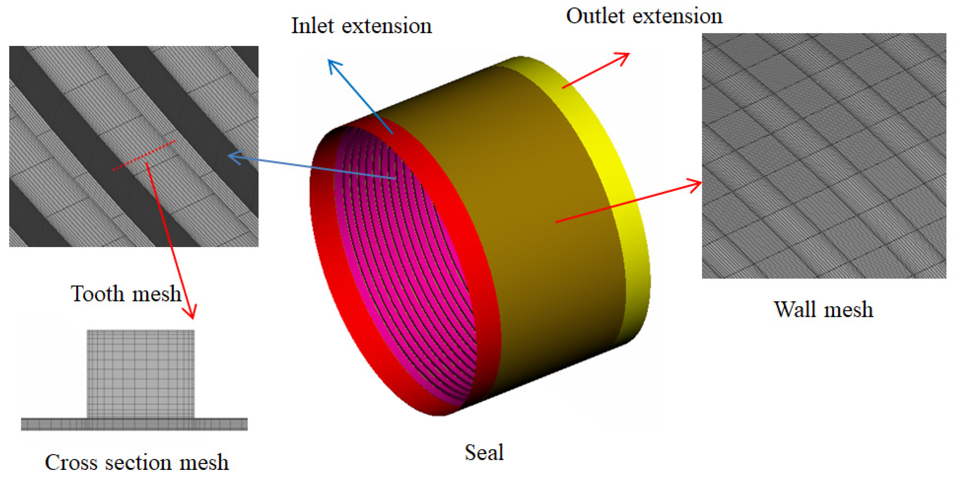
Figure 1. Fluid seal mesh.
Lubricants 10 00240 g001
Figure 2. Geometry of parallel grooved seal (mm).
Lubricants 10 00240 g002
Figure 3. Fluid mesh independence study.
Lubricants 10 00240 g003
Figure 4. Solid seal mesh.
Lubricants 10 00240 g004
Figure 5. Solid seal structure and data coupling.
Lubricants 10 00240 g005
Figure 6. Flow chart of thermal and dynamic loads coupling.
Lubricants 10 00240 g006
Figure 7. The change of seal tooth height and seal clearance: (a) 50 °C water seal, (b) 86 °C water seal.
Lubricants 10 00240 g007
Figure 8. Pressure distribution (n = 4000 r/min, Δp = 8.25 bar).
Lubricants 10 00240 g008
Figure 9. Circumferential velocity (n = 4000 r/min, Δp = 8.25 bar).
Lubricants 10 00240 g009
Figure 10. Axial velocity (n = 4000 r/min, Δp = 8.25 bar).
Lubricants 10 00240 g010
Figure 11. Whirling motion and rotating motion of the rotor. (a) Whirling model. (b) Rotor rotation.
Lubricants 10 00240 g011
Figure 12. Whirling orbit.
Lubricants 10 00240 g012
Figure 13. Rotor motion. (a) Motion in time-domain. (b) Motion in frequency-domain.
Lubricants 10 00240 g013
Figure 14. Fluid-induced forces. (a) Force in time-domain. (b) Force in frequency-domain.
Lubricants 10 00240 g014
Figure 15. Fitting curve of the fluid-induced forces. (a) radial fluid force. (b) tangential fluid force.
Lubricants 10 00240 g015
Figure 16. Test rig. (a) Seal test rig, (b) centrifugal pump, (c) high-temperature water irrigation.
Lubricants 10 00240 g016
Figure 17. Test schematic.
Lubricants 10 00240 g017
Figure 18. Calculations versus measured leakage flow rate (Δp = 8.25 bar).
Lubricants 10 00240 g018
Figure 19. Calculations versus measured drag power loss (n = 6000 r/min).
Lubricants 10 00240 g019
Figure 20. Rotordynamic coefficients versus pressure drop (n = 4000 r/min). (a) direct stiffness. (b) direct damping. (c) cross-coupling stiffness. (d) cross-coupling damping.
Lubricants 10 00240 g020aLubricants 10 00240 g020b
Figure 21. The effective stiffness at different pressure drops (n = 4000 r/min).
Lubricants 10 00240 g021
Figure 22. The effective damping at different pressure drops (n =4000 r/min).
Lubricants 10 00240 g022
Figure 23. Rotordynamic coefficients versus rotational speeds (Δp = 8.25 bar). (a) direct stiffness. (b) direct damping. (c) cross-coupling stiffness. (d) cross-coupling damping.
Lubricants 10 00240 g023
Figure 24. The effective stiffness at different rotational speeds (Δp = 8.25 bar).
Lubricants 10 00240 g024
Figure 25. The effective damping at different rotational speeds (Δp = 8.25 bar).
Lubricants 10 00240 g025
Table 1. Geometrical parameters and operational conditions in CFD analyses.
FluidsWater (20 °C\50 °C\86 °C)
Outlet Pressure (bar)1.0
Inlet preswirl ratio λ0.0
Rotational speed n (kr/min)2.0, 4.0, 6.0
Rotor diameter D (mm)102
Seal radial clearance cr (mm)0.203
Groove depth d (mm)1.524
Land width w (mm)1.524
Groove length s (mm)1.524
Table 2. Physical property parameters of water at different temperatures.
T (°C)205086
ρ (kg/m3)996.9988.1967.9
C (J/kg/K)418041744203
μ (Pa·s)0.0010.00054940.000331
K (W/m/K)0.5980.6480.678
Table 3. 20 °C Water Seal deformation (mm) (n = 4000 r/min, Δp = 2.08 bar).
LoadsNO.1 ToothNO.7 ToothNO.14 Tooth
RadialTotalRadialTotalRadialTotal
p−3.4535 × 1055.2086 × 105−2.3961 × 1054.5765 × 105−1.4917 × 1054.1742 × 105
ω6.1277 × 1056.1278 × 1056.0835 × 1056.0837 × 1056.1278 × 1056.1279 × 105
T−1.6365 × 1031.6364 × 103−1.6361 × 1031.6362 × 103−1.6348 × 1031.6349 × 103
p, ω, T−1.6097 × 1031.6102 × 103−1.5992 × 1031.5997 × 103−1.5884 × 1031.5889 × 103
Table 4. 50 °C Water seal deformation (mm) (n = 4000 r/min, Δp = 2.08 bar).
LoadsNO.1 ToothNO.7 ToothNO.14 Tooth
Radial TotalRadialTotalRadial Total
p−3.3425 × 1057.4469 × 105−2.3291 × 1057.0512 × 105−1.4632 × 1056.8145 × 105
ω6.1275 × 1056.1277 × 1056.0835 × 1056.0836 × 1056.1277 × 1056.1278 × 105
T2.1284 × 1022.1285 × 1022.1291 × 1022.1293 × 1022.1279 × 1022.1280 × 102
p, ω, T2.1326 × 1022.1327 × 1022.1328 × 1022.1329 × 1022.1312 × 1022.1313 × 102
Table 5. 86 °C Water seal deformation (mm) (n = 4000 r/min, Δp = 2.08 bar).
LoadsNO.1 ToothNO.7 ToothNO.14 Tooth
Radial TotalRadialTotalRadial Total
p−3.2746 × 1053.918 × 105−2.2987 × 1053.1463 × 105−1.4778 × 1052.6051 × 105
ω6.3653 × 1056.3658 × 1056.3224 × 1056.3228 × 1056.3676 × 1056.3669 × 105
T4.8397 × 1024.8401 × 1024.8533 × 1024.8535 × 1024.8396 × 1024.8401 × 102
p, ω, T4.8428 × 1024.8431 × 1024.8574 × 1024.8575 × 1024.8447 × 1024.8449 × 102
Table 6. Dynamic coefficients.
CFD Experiment [14,15,16,17,18,19,20,21,22,23,24,25,26,27,28,29]Error
K(N/m)−9.15 × 105−6.67 × 10537.2%
k(N/m)2.33 × 1062.55 × 1068.6%
C(N·s/m)7.14 × 1035.87 × 10321.6%
c(N·s/m)4.17 × 1035.25 × 10320.6%
Publisher’s Note: MDPI stays neutral with regard to jurisdictional claims in published maps and institutional affiliations.