Article

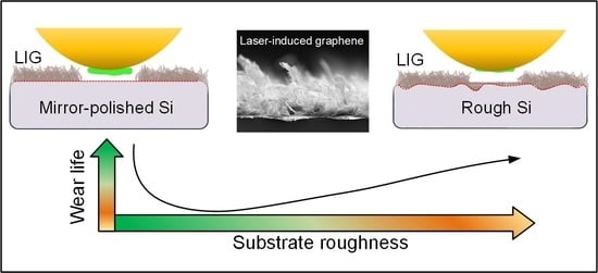
Effect of Substrate Roughness on the Friction and Wear Behaviors of Laser-Induced Graphene Film

Institute of Nanosurface Science and Engineering (INSE), Shenzhen University, Shenzhen 518060, China
*
Author to whom correspondence should be addressed.
These authors contributed equally to this work.
Lubricants 2022, 10(10), 239; https://doi.org/10.3390/lubricants10100239
Submission received: 2 September 2022 / Revised: 22 September 2022 / Accepted: 24 September 2022 / Published: 27 September 2022
(This article belongs to the Special Issue State-of-the-Art of Tribology in China)

Abstract

:
A rough substrate usually induces severe detriments limiting the performance of anti-friction materials that would lead to an increase in both the friction coefficient and wear rate. In this work, we found that a laser-induced graphene (LIG) film had a good friction adaptability on both mirror-polished and rough Si substrates. The friction coefficient of the LIG increased from 0.11 to 0.24 and the substrate roughness increased from 1.4 nm to 54.8 nm, while the wear life of the LIG was more than 20,000 cycles for both the mirror-polished and rough Si substrates. Optical microscope, Raman spectroscopy and scanning electron microscope analyses revealed a friction mechanism evolution of the LIG films on Si substrates with a different roughness. For the mirror-polished Si substrate, thick and dense graphene nanocrystallite transfer films could form on the counterpart balls, which guaranteed a long and stable wear. For the rough Si substrate, although the asperities on the rough surface would plough the counterpart balls and destabilize the transfer film formation, grooves could effectively store a compressed LIG, benefiting a stable anti-wear performance and reducing the abrasive wear at the friction interface. This work showed that a LIG film had outstanding friction adaptability on Si substrates with a different roughness and that it can be fabricated in a single-step economic process, indicating bright practical prospects in the solid lubrication fields.

Graphical Abstract

1. Introduction

Laser-induced graphene (LIG) [1], a kind of three-dimensional (3D) porous graphene, has drawn significant attention owing to its excellent prospects for flexible sensors [2], super-capacitors [3] and electro-catalysts [4]. As for the conventional graphene fabrication methods, such as exfoliation [5,6], chemical synthesis [7], epitaxial growth [8] and chemical vapor deposition [9], extra conditions are usually required including a vacuum chamber, high temperatures. They are also time-consuming processes. For LIG, the one-step fabrication method can overcome the sophisticated processes and equipment requirements of the conventional methods [10], making it a low-cost fabrication method and leading to great potentials in various application fields. As for the tribology, graphene has been proved to possess ultra-low friction and high wear-resistance properties at the nano-/micro-scale under a proper contact state and atomic-smooth substrate [11,12,13]. At the macro-scale, the friction performance of graphene would be influenced by the entire sophisticated tribo-system, including the contact pressure [14], atmosphere [15], humidity [16] and substrate condition [17]. Even if maintaining the long-term superlubricity of graphene at the macro-scale is still a challenge [18], graphene has still exhibited some impressive anti-wear properties [19], leading to the continuous focus and research on it. LIG, as a low-cost and easily producible new graphene-based material, is also a potential lubricant at a macro-scale application, but its macro-scale lubrication performance has still remained to be explored.
Substrate roughness usually plays an important role in deciding the friction and wear performances of lubrication materials [20]. In most cases, a large surface roughness usually induces an increase in both the friction [21] and wear [22]. With an increase in the substrate roughness, the friction coefficient would increase owing to a limited plastic deformation [23] and a high roughness would induce a higher maximum contact pressure [24] and higher flash temperature [25] at the friction interfaces. With the generation of wear debris particles under high contact pressure [26], the wear mechanisms will change from adhesive wear to abrasive wear and induce a higher wear rate [27]. Faced with the bad influence of a large roughness on the performance of lubricants, researchers have tried various methods to reduce the roughness, including etching [28], doping [29] and increasing a film’s thickness [30], but too large a substrate roughness will limit the effects of these methods.
As for graphene, the influence of the substrate roughness on the friction performance is different for the nano-/micro-scale and the macro-scale. At the nano-/micro-scale, the low surface energy of graphene would induce a low adhesion on various substrates [31]. Thus, an atomic-smooth substrate is needed to achieve a good contact and avoid the “puckering effect”, which can severely increase the friction coefficient of graphene [32]. At the macro-scale, the difficult point is that the chemical inertness makes graphene difficult to form a solid tribolayer on many tribopairs [33]. Because the transferred graphene plays an important role in friction, some works have tried to use a laser to fabricate microgrooves to store the graphene and enhance the anti-wear performance [34,35]. In industrial production, realizing an atomic-smooth surface or using a laser to process the surface usually requires extra time and costs. Realizing a good adaptability of a lubricant in a poor substrate situation is of high importance in then prompting its industrial application.
In this work, we systematically studied the friction and wear performances of LIG films fabricated on Si substrates with a different surface roughness. The influence of the substrate roughness on the friction coefficient and wear life of LIG films was investigated. The evolution of the friction mechanisms under a different substrate roughness was revealed with an analysis of the friction interfaces.

2. Materials and Methods

Silicon substrates (p-type <100>) were firstly cut into small squares with a size of 20 mm × 20 mm. To apply different abrasive conditions for different Si substrates, emery papers with different grit grade of 400, 1000, 1500 and 2000 were used to grind the Si substrates. After the Si substrates were ground by the emery papers, the surface roughness’ of the Si substrates were measured by a profilometer (Bruker, DEKTAK-XT, Billerica, MA, USA). The surface roughness of the different samples are presented in Table 1. The LIG film fabricated on a mirror-polished Si substrate was named as R-1 and the other samples were named as R-15, R-21, R-36 and R-55, depending on the values of their surface roughness. Then, the original and ground Si substrates were cleaned by an ultrasonic cleaner in an acetone bath for 20 min. After the cleaning process, a polyimide solution (Hongfu Industrial Co., Ltd., Dongguan, China) was coated on those Si substrates using a spin coater (KW-4A) with a rotation rate of 5000 rpm for 12 s to obtain uniform polyimide (PI) films. After that, the PI coated substrates were transferred to a heater at 150 °C for 1 min to evaporate the solvent quickly. Next, a curing process was conducted by setting those films on a heater at 260 °C for 5 min to obtain PI films with thicknesses around 2.38 μm. Finally, the solid PI films were processed by being directly written using a continuous focusing laser (Shanghai Diaotu Tech. Co., Ltd., L3 Pro, Shanghai, China; wavelength, 450 nm; power, 7 W; scanning speed, 20 mm/s) to fabricate the LIG films.
The plane and cross-sectional images of a LIG film on the original Si substrate were characterized by a scanning electron microscope (SEM; Thermo Fisher Scientific, Scios, Waltham, MA, USA) operated at an acceleration voltage of 5 kV. The nanostructures of the LIG films were analyzed with Raman spectroscopy (Horiba, HR-Resolution; wavelength of 532 nm, Kyoto, Japan) and a transmission electron microscope (TEM; Thermo Fisher Scientific, Titan3 Themis G2, Waltham, MA, USA). A plane view TEM specimen was prepared by scratching the LIG film surface with a diamond pen, and then transferring the flakes onto a copper micro grid.
Frictional tests of the LIG films sliding against brass balls (with a radius of 3.17 mm) were performed with a pin-on-disk tribometer. The normal load was 2 N. The sliding velocity was 26.4 mm/s, corresponding to a constant disk rotation rate of 180 rpm with a friction radius of 1.4 mm. The frictional tests would stop when operated for 30,000 cycles if the samples did not fail for the saving time, which meant that the maximum test time for a sample was about 3 h. The tests were operated in a clean room at the temperature of 24 °C and a relative humidity of 60–65% in the atmosphere. Each film was tested for more than five times. The structures of the transfer films on the brass ball surfaces were analyzed with the SEM, energy dispersive spectrometer (EDS), optical microscope and Raman spectroscopy. The structures of the wear tracks were analyzed with an optical microscope and Raman mapping. The cross-sectional lines of the Si substrates and wear tracks were measured for 5 times by a profilometer for each sample and the cross-sectional SEM images of the wear tracks of the R-1 and R55 samples were fabricated by cutting from the worn substrates using a focused ion beam (FIB; Thermo Fisher Scientific, Scios, Waltham, MA, USA). Pt layers were subsequently deposited on the specimens to increase the conductivity and prevent possible damage during the fabrication process.

3. Results

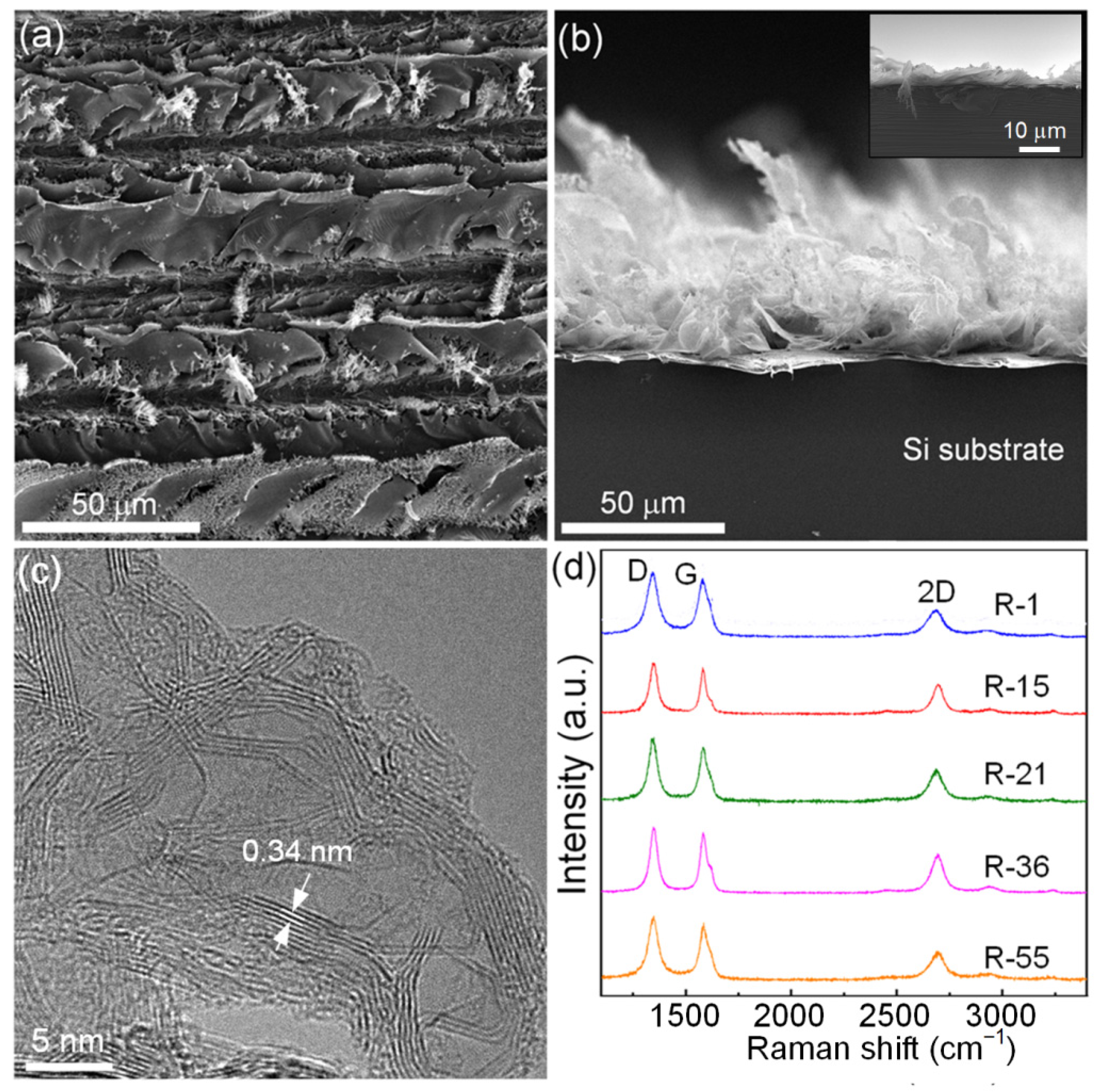
3.1. Structure Characterization of LIG Film

Figure 1a,b presents the plane view and cross-sectional SEM images of the R-1 sample. It can be observed that the LIG film was formed by small carbon flakes. According to the plane and cross-sectional SEM images, the surface structure of the LIG film consisted of carbon plates with random orientations, which was attributed to the instant releasing of the pyrolysis gases formed during the carbonization process of PI film [3,36,37]. During the carbonization process, the instant releasing pyrolysis gases resulted in a “bombing” effect and the formation of protruded loose and exploded features (Figure 1b). The plane view TEM image of the R-1 is presented in Figure 1c, where it is clear that some layer structure with an interplanar spacing of ~0.34 nm was observed, which confirmed the existence of a nanocrystalline graphene structure. The inset image in Figure 1b presents the SEM image of the R-1 taken at a tilted angle of 90° between the sample and the camera to exhibit the thickness of the LIG film. The thicknesses were measured around 5 to 9 μm in spite of the different substrate roughness of the different samples. The thickness of the LIG films increased by a factor of 2 to 4 compared with that of the original PI films, which was consistent with some other reports [38].
Figure 1d shows the Raman spectra of the LIG films fabricated on different Si substrates. It can be confirmed that the abrasive conditions of the Si substrate did not induce any notable structural change in the LIG films. All the Raman spectra of the LIG films had a similar structure with an isolated D band around 1350 cm−1, a G band around 1590 cm−1 and a prominent 2D band around 2690 cm−1, indicating the existence of graphene sheets in the LIG film [39].

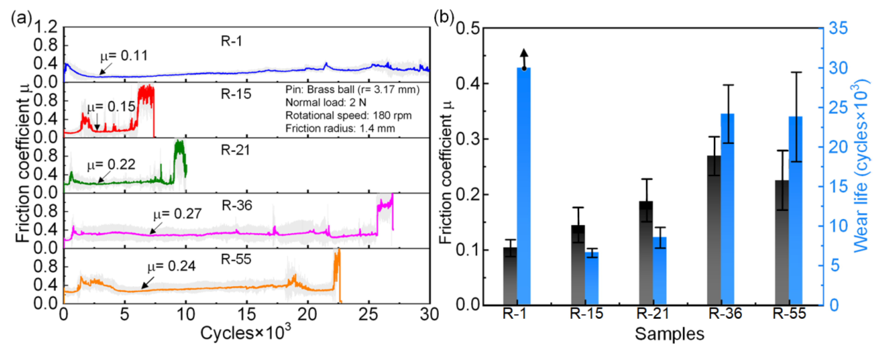
3.2. Frictional Behaviors

The friction coefficient curves of the LIG films on different Si substrates are presented in Figure 2a. As for the R-1, the friction coefficient first decreased to 0.11 in the first 5000 cycles and then remained at a relatively stable value. The wear life of this film was more than 30,000 cycles and the friction coefficient curve during the test was relatively stable so that no sudden jump could be observed; however, for those LIG films fabricated on Si substrates ground by different emery papers, the friction behaviors changed significantly. For the R-15 and R-21 samples, the friction coefficient curves exhibited a sudden jump less than 10,000 cycles, indicating a friction failure of the films, while for the R-36 and R-55 samples, the friction coefficient curves were sustained for more than 20,000 cycles before a sudden jump happened. These results suggest a counter-intuitive outcome, namely, that for the LIG films fabricated on substrates with a relatively large roughness, a rougher substrate would favor a relatively long wear life of the LIG film.
Figure 2b summarizes the friction coefficients and wear life of the different samples. The R-1 had the lowest friction coefficient of ~0.10 and the longest wear life. For the R-15 and R-21, a slight increase in the Si substrate roughness would lead to a mild increase of the friction coefficient of around 0.15 while the wear life was shortened severely, but with a further increase in the substrate roughness, the friction coefficient would keep increasing to a relatively stable value of around 0.24, while the wear life of these samples increased to about 25,000 cycles; thus, indicating that a LIG film can maintain a good anti-wear performance when fabricated on a substrate with a large roughness.

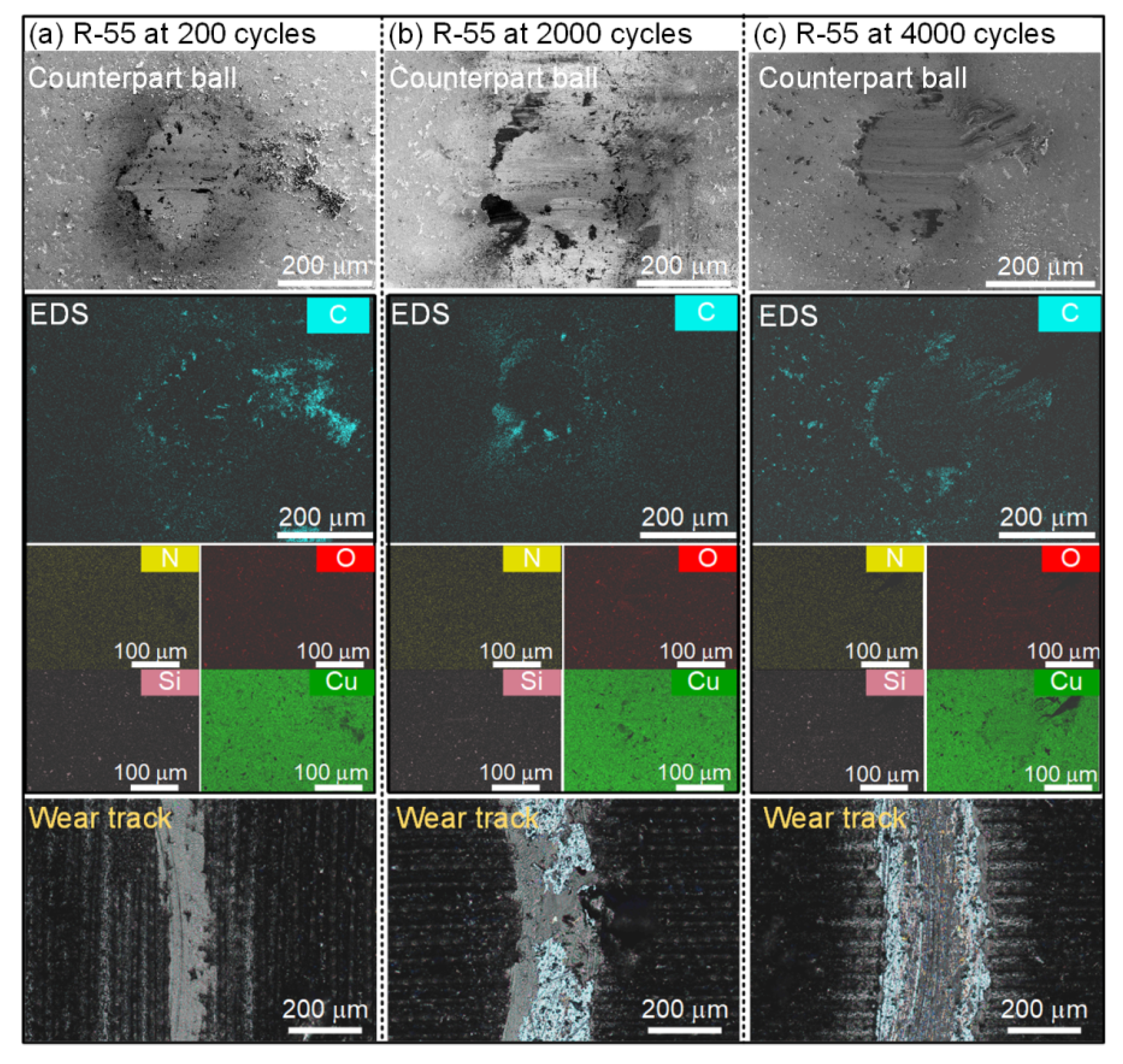
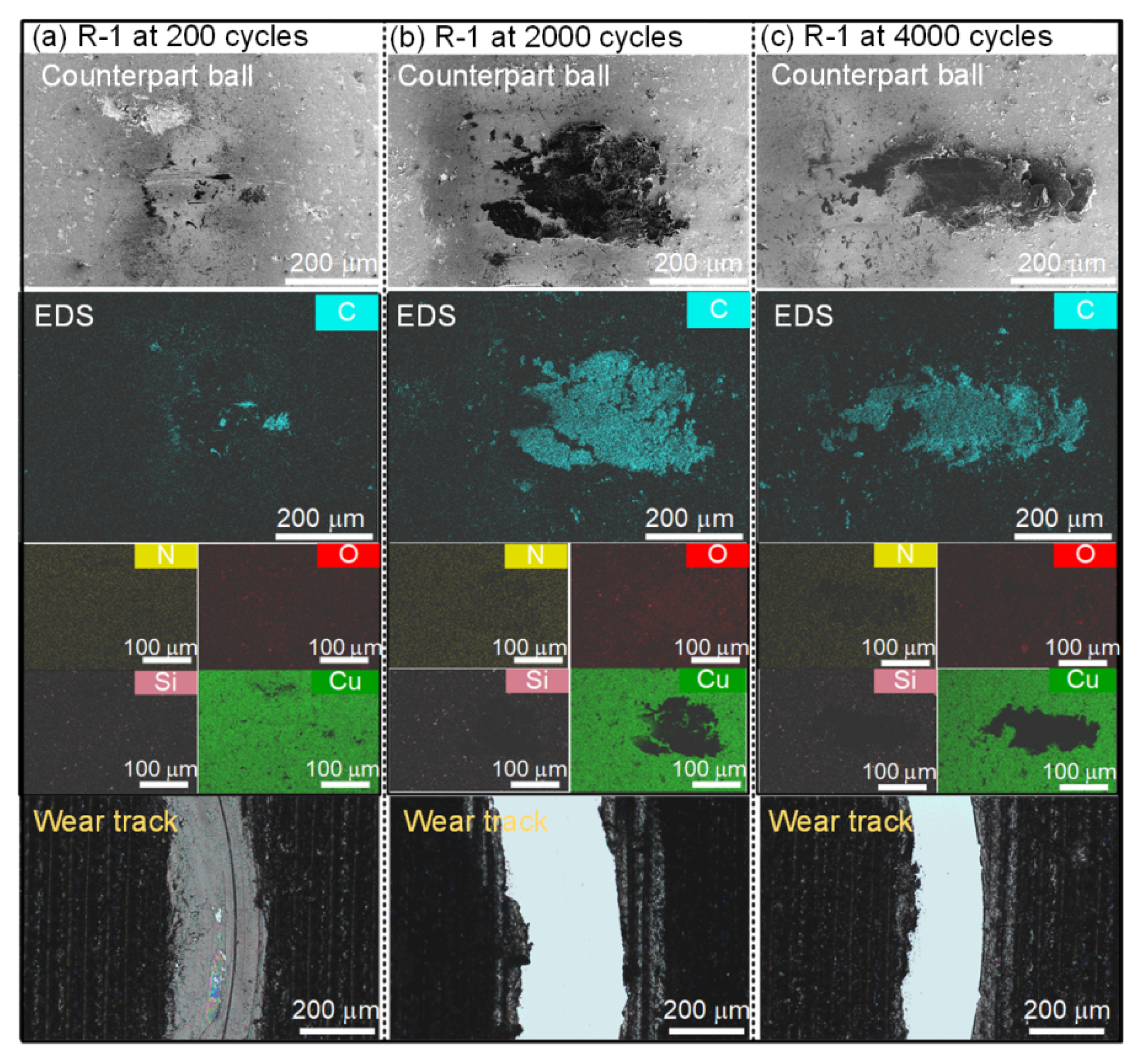
3.3. Run-In Process Characterization

Understanding the run-in process is important for elucidating the performance of different friction processes. Figure 3 presents the SEM images and EDS analyses of the same areas of the counterpart balls as well as optical photos of the wear tracks of the R-1 at the first 200, 2000 and 4000 cycles, respectively. Based on Figure 3a, it can be observed that during the first 200 cycles, only a small amount of the transfer film was formed on the counterpart ball and the EDS analysis indicated that the transfer film was formed by C. The optical photo of the wear track indicates that the LIG film was compressed from the original loose structure. With the increase of the friction cycles to 2000 and 4000 cycles, it could be found that a dense transfer film was formed on the counterpart balls according to the SEM images and EDS analyses of the contact positions, as shown in Figure 3b,c. It can be observed that before 2000 cycles, the as-fabricated LIG film had transferred to the counterpart ball and that no apparent LIG could be found in the wear tracks after 2000 cycles. Combined with the friction coefficient curves of R-1 presented in Figure 2a, it can be inferred that once the dense transfer film formed on the counterpart ball, a steady low-friction coefficient could be obtained. The EDS analyses indicated that the contents of O and N were relatively small in the transfer films. The signal of Si remained almost unchanged, which meant that the substrate did not endure any notable wear. Only the signal of Cu changed after wear, owing to some areas that were covered with a transfer film; thus, it can be inferred that the friction and wear process was dominated by the restructured transfer film of the LIG.
Figure 4 presents the SEM images and EDS analyses of the same areas of the counterpart balls as well as optical photos of the wear tracks of R-55 at the first 200, 2000 and 4000 cycles, respectively. Based on the SEM and EDS analyses presented in Figure 4a–c, it can be seen that only a small amount of transfer films were formed around the contact points of the counterpart balls, which can be confirmed by the C signals in the EDS mappings. The optical photos of the wear tracks presented in Figure 4a–c show a different evolution of the LIG in the wear tracks. Different from the condition of the R-1 at 2000 cycles, LIG could still be observed in the wear tracks at 2000 cycles for the R-55, but the distribution of the LIG was relatively random, which may be the reason causing the fluctuation of the friction coefficient during the run-in period of the R-55 as presented in Figure 2a. When it came to 4000 cycles, many black carbon materials could still be observed in the wear track of the R-55, which was totally different from that of the R-1. During the first 4000 cycles, the distributions of O, N, Si and Cu remained almost unchanged, which indicates the influence of the environment was low and that the Si substrate did not endure any notable wear.

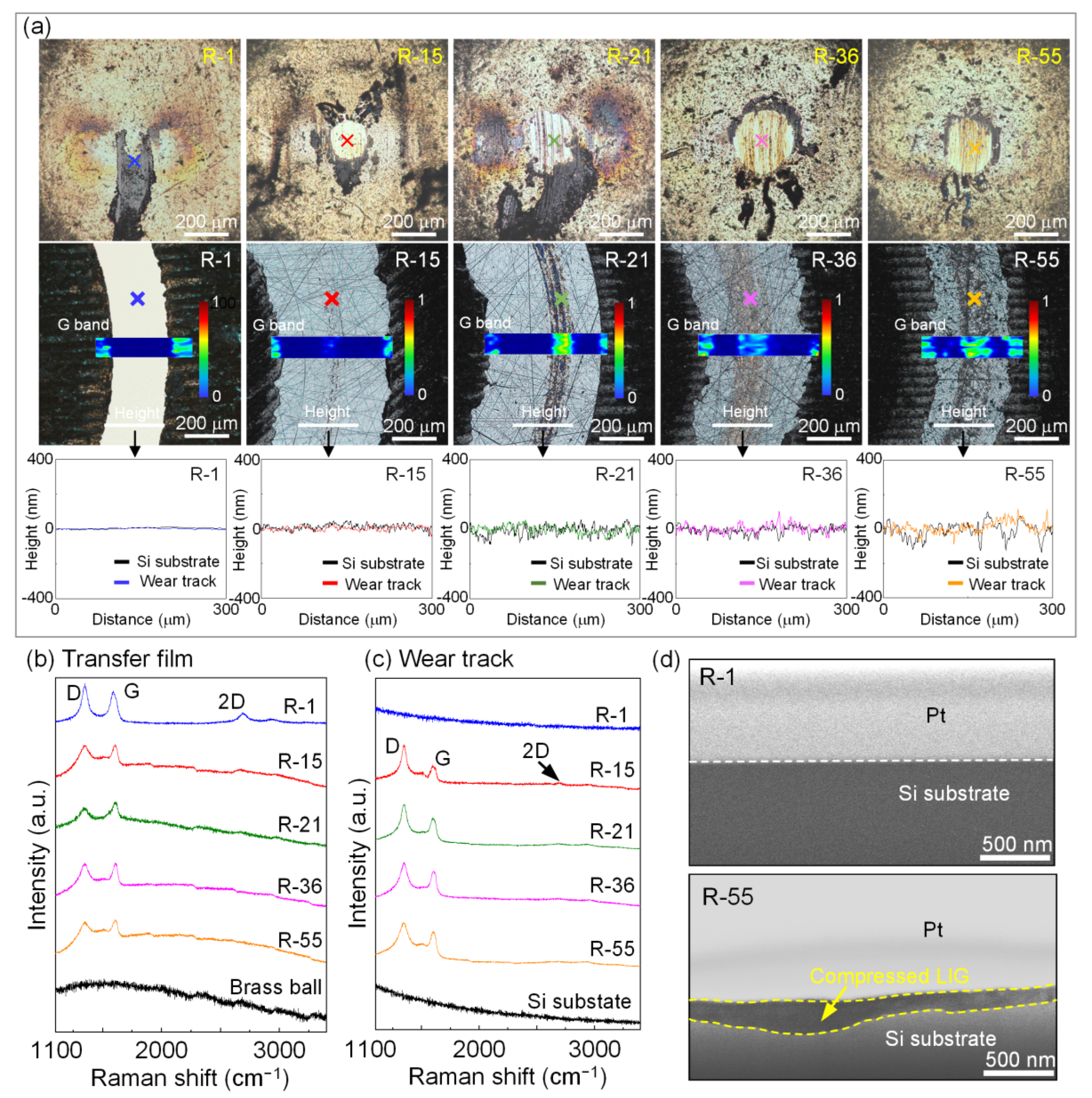
3.4. Wear Area Characterization

In order to understand the reason that influences the frictional behaviors of LIG fabricated on silicon substrates with a different roughness, the counterpart balls and wear tracks after sliding for 5000 cycles were characterized by an optical microscope, Raman spectroscopy, profilometer and SEM, as presented in Figure 5. The colored bars presented in the optical photos of the wear tracks indicate the relative intensity of the G band of the Raman spectra. The black transverse section lines were obtained from the Si substrate before being coated with the LIG films and the transverse section lines in other colors were obtained in the wear tracks after the frictional tests. In Figure 5a, for the R-1, it can be observed that a thick transfer film was formed on the surface of the counterpart ball, while no film remained in the wear track. The formation of a thick and dense transfer film was attributed to the restructure of loose, exploded graphene nanocrystallites into the compact nanocrystalline transfer film under a normal and shear force during friction [40]. The wear track was further characterized by Raman mapping of the G band signal around 1570 cm−1 and no identifiable carbon signal could be found. By comparing the transverse section lines of the wear track and the original Si substrate, it was found that no observable wear occurred to the Si substrate. For the R-15 sample, the transfer film on the counterpart ball was distributed around the contact area according to the optical image. In the wear track of the R-15, clear scratches induced by the emery paper sanding could be observed. The Raman mapping result indicated that a weak signal of the G band could be found at the middle part of the wear track. The transverse section lines showed little difference between the ground substrate and the wear track. For the samples R-21, R-36 and R-55, a tendency could be found that with a substrate roughness increase, the area of the transfer film that formed on the counterpart ball decreased, while the width of the carbon materials that remained in the wear tracks became wider, and both can be observed in the optical photos and the Raman mapping results. The reason that induced the transfer film to adhere less to the counterpart ball can be ascribed to the asperities on the rough surface, which ploughed the counterpart balls and destabilized the transfer film formation on the counterpart balls [41]. For the R-55, the transverse section lines showed a clear difference between the ground substrate and the wear track, and that the fluctuation of the wear track became milder when comparing it with that of the original ground substrate, which may indicate that the roughness valleys were filled by the LIG.
It should be noted that the widths of the different wear tracks also provided some interesting information. For the wear track of the R-1, it had the narrowest wear track compared with that of the other samples, which was likely induced by the compact, graphene nanocrystallite transfer film on the counterpart ball [40]. The porous flake structure of graphene can facilitate the formation of a graphene nanocrystallite transfer film at the contact area [42], which can effectively reduce the friction and provide the benefit of a long wear life [43]. The friction process of the R-1 likely occurred between the graphene nanocrystallite transfer film and the Si substrate, which would have reduced the wear of the soft brass ball and contributed to the narrow wear track. For the wear tracks of the R-15 and R-21 samples, considering only a small amount of transfer film was formed at the contact position of the counterpart ball and that a small area of wear track was covered by carbon material, the friction process should mainly have occurred between the brass ball and the Si after a LIG film was worn out, which resulted in the wide wear tracks. For the wear tracks of the R-36 and R-55 samples, because larger areas of the wear tracks were covered with carbon materials, the friction process should mainly have occurred between the brass balls and carbon materials. The remaining carbon material would have been formed by a graphene nanocrystallite, which can easily slide between the layers and can limit the wear. As a result, relatively narrower wear tracks were formed for the R-36 and R-55 samples.
Figure 5b, c present the Raman spectra of the points marked in both the counterpart balls and the wear tracks of different samples. As for the transfer film formed on the counterpart ball worn against the R-1 sample, the shape of the D band was sharp and narrow, indicating a relatively regular nanocrystalline structure [44] and it was found that a clear 2D band around 2700 cm1 could be observed in this condition. For the other transfer films, the signal intensity of the carbon material decreased notably and the width of the D band became wider, which indicates a more disordered carbon structure [44]. In this condition, no identifiable 2D band could be observed, which can be deduced as a degradation of the graphene structure. When it came to the Raman spectra of the wear tracks, it could be found that no carbon signal was found in the wear track of the R-1 sample, which was in good accordance with the optical photo. For the other wear tracks, similar structures of the Raman spectra could be found, and a clear D band and G band could be observed, which implies that some carbon materials remained in the wear track.
Figure 5d presents the cross-sectional SEM images of the wear tracks of the R-1 and R-55 samples after sliding for 5000 cycles. As for the R-1, the Si substrate could be confirmed to be very flat and no apparent damage or carbon material could be found on the Si substrate, which was in accordance with the optical photo and Raman spectra results. When it came to the R-55, the LIG was stored in grooves, which was confirmed by the contrast in color according to the cross-sectional SEM image, as marked by the yellow dot lines. Combined with the cross-sectional SEM images and Raman analyses on the wear tracks, it could be verified that the LIG was compressed during the friction process and stored in the grooves of the wear tracks when the surface roughness of the Si substrates was large.

4. Discussion

According to the recent studies on the macro-friction of graphene, the fast consumption of a weakly adhered graphene at the friction interface has been the major drawback that has limited the anti-wear performance of graphene film. Faced with this problem, researchers have tried to fabricate a regular texture [34] and enhance the interfacial bonding strength [45] to maintain a relatively long wear life. The effect of texture is to store lubricant and grinding debris [46,47,48] and to reduce the effective contact area of a friction pair surface [49], but not all texture can improve the friction performance, and a faulty design of texture would deteriorate both the friction and wear [50]. The effect of enhancing the interfacial bonding strength is to increase adhesion and form a stable transfer film. In a word, the key purpose is to ensure the graphene remains in the friction interface and, thus, realize a stable wear process.
In this work, the above tests and characterizations present interesting results in that a LIG film can possess a good anti-wear performance on both mirror-polished and rough Si substrates. The analyses on the counterpart balls and wear tracks have revealed an evolution of the friction mechanisms with an increase in the substrate roughness. According to the optical photos and Raman spectra results presented in Figure 3 and Figure 5, only for a mirror-polished Si condition, could a graphene nanocrystallite transfer film be clearly observed at the contact position of the counterpart ball. Once the substrate became rough, the amount of the transfer films decreased significantly at the contact position of the counterpart balls, and only a Raman spectrum could confirm the existence of some carbon material, indicating that rough substrates would severely impede the formation of a graphene nanocrystallite transfer film on a counterpart ball. As for the wear track, a narrow and no-carbon signal observed wear track was obtained for the mirror-polished Si substrate condition. With an increase in the substrate roughness, the spread areas of carbon material in the grooves of the wear tracks increased, and the width of the wear tracks firstly became larger and then slightly decreased, which means that the contact area of the counterpart ball decreased, indicating a wear decrease in the counterpart ball.
Thus, a schematic diagram is presented in Figure 6 to help understand the evolution of the friction mechanisms. For the mirror-polished Si substrate condition, the loose structure LIG film firstly formed a thick and dense transfer film on the counterpart ball. Because the substrate was mirror-polished smooth, the transferred graphene film was slightly consumed with a slow process of amorphization of the graphene structure under a normal and shear force [51]. As a result, a long stable friction was obtained, as in the schematic diagram presented in Figure 6a. For the large roughness Si substrate condition, no apparent transfer film could be found at the contact positions of the counterpart balls. The asperities on the rough surface ploughed the counterpart balls and destabilized the transfer film formation on the counterpart balls [41]. Although the Raman results indicated that carbon materials could still be detected at the counterpart balls, the transfer films were hardly observed at the contact points according to the optical images. At the same time, the Raman signal of the carbon material was strong in the wear track, compared with that of the mirror-polished and low-roughness conditions; thus, it could be concluded that the LIG was compressed and trapped in the grooves of the Si substrate, which worked as the regular texture [34]. Therefore, in this situation, the friction mainly happened between the counterpart ball and the compressed LIG trapped in the grooves. A very small amount of transfer film may have existed at the friction interface, but it may have only played a less dominant role in this condition. The existence of LIG at the interface could reduce the contact stress [52] and ss a result, a relatively long stable friction could be obtained in this condition, as in the schematic diagram presented in Figure 6b. The long stable friction of LIG on the rough Si substrates suggests that as long as enough deep grooves exist, the lubricant store effect can benefit with a long and stable wear life.

5. Conclusions

In this work, laser-induced graphene (LIG) films were fabricated on Si substrates with a different surface roughness using the direct laser writing method. With an increase of the substrate roughness from 1.4 nm to 54.8 nm, the friction coefficient of the LIG kept increasing from 0.11 to 0.24, while the wear life firstly decreased severely from more than 30,000 cycles to less than 10,000 cycles when the substrate roughness increased to 21.2 nm. It then increased to more than 20,000 cycles when the substrate roughness was higher than 35.6 nm. The friction mechanism evolution was revealed as: (1) for the mirror-polished Si substrate, a thick and stable graphene nanocrystallite transfer film could form and remain on the counterpart ball, making friction occur between the graphene nanocrystallite transfer film and the Si substrate; (2) for Si substrate with a relatively small surface roughness, LIG could not be preserved on either the counterpart balls or the Si substrates for a significant time, causing severe friction to occur mainly between the counterpart balls and the Si substrates; (3) for the Si substrates with a large surface roughness, LIG was compressed and stored in the grooves of the Si substrates, causing the friction to mostly occur between the counterpart balls and the compressed LIG. This work revealed the good friction adaptability of a LIG film and clarified the friction mechanism evolution of LIG films fabricated on Si substrates with a different surface roughness. Combined with the merits of being low-cost and large-scale producible, LIG film shows a bright potential in industry applications as a solid lubricant.

Author Contributions

Conceptualization, C.C., Z.H. and P.X.; investigation, Z.H. and P.X.; methodology, C.C. and Z.H.; writing—original draft preparation, P.X. and Z.H.; writing—review and editing, C.C. and P.X.; project administration, C.C.; funding acquisition, C.C. All authors have read and agreed to the published version of the manuscript.

Funding

This research was funded by the National Natural Science Foundation of China (No. 52175179), Guangdong Basic and Applied Basic Research Foundation (No. 2022A1515010555) and Shenzhen Science and Technology Program (No. JCYJ20210324100406018).

Data Availability Statement

Not applicable.

Acknowledgments

The authors would like to acknowledge the Electron Microscopy Center (EMC) of Shenzhen University for the technical supports in TEM and FIB.

Conflicts of Interest

The authors declare no conflict of interest.

References

  1. Ye, R.; James, D.K.; Tour, J.M. Laser-induced graphene: From discovery to translation. Adv. Mater. 2019, 31, 1803621. [Google Scholar] [CrossRef] [PubMed]
  2. Tao, L.Q.; Tian, H.; Liu, Y.; Ju, Z.Y.; Pang, Y.; Chen, Y.Q.; Wang, D.Y.; Tian, X.G.; Yan, J.C.; Deng, N.Q.; et al. An intelligent artificial throat with sound-sensing ability based on laser induced graphene. Nat. Commun. 2017, 8, 14579. [Google Scholar] [CrossRef] [PubMed]
  3. Lin, J.; Peng, Z.W.; Liu, Y.Y.; Ruiz-Zepeda, F.; Ye, R.Q.; Samuel, E.L.G.; Yacaman, M.J.; Yakobson, B.I.; Tour, J.M. Laser induced porous graphene films from commercial polymers. Nat. Commun. 2014, 5, 5714. [Google Scholar] [CrossRef] [PubMed]
  4. Ye, R.Q.; Peng, Z.W.; Wang, T.; Xu, Y.N.; Zhang, J.B.; Li, Y.L.; Nilewski, L.G.; Lin, J.; Tour, J.M. In situ formation of metal oxide nanocrystals embedded in laser-induced graphene. ACS Nano 2015, 9, 9244–9251. [Google Scholar] [CrossRef]
  5. Novoselov, K.S.; Geim, A.K.; Morozov, S.V.; Jiang, D.; Zhang, Y.; Dubonos, S.V.; Grigorieva, I.V.; Firsov, A.A. Electric field effect in a atomically thin carbon films. Science 2004, 306, 666–669. [Google Scholar] [CrossRef]
  6. Viculis, L.M.; Mack, J.J.; Mayer, O.M.; Hahn, H.T.; Kaner, R.B. Intercalation and exfoliation routes to graphite nanoplatelets. J. Mater. Chem. 2005, 15, 974–978. [Google Scholar] [CrossRef]
  7. Zhou, X.; Zhang, J.; Wu, H.; Yang, H.; Zhang, J.; Guo, S. Reducing graphene oxide via hydroxylamine: A simple and efficient route to graphene. J. Mater. Chem. C 2011, 115, 11957–11961. [Google Scholar] [CrossRef]
  8. Juang, Z.; Wu, C.; Lo, C.; Chen, W.; Huang, C.; Hwang, J.; Chen, F.; Leou, K.; Tsai, C. Synthesis of graphene on silicon carbide substrates at low temperature. Carbon 2009, 47, 2026–2031. [Google Scholar] [CrossRef]
  9. Guo, S.; Dong, S.; Wang, E. Three-Dimensional Pt-on-Pd bimetallic nanodendrites supported on graphene nanosheet: Facile synthesis and used as an advanced nanoelectrocatalyst for methanol oxidation. ACS Nano 2010, 4, 547–555. [Google Scholar] [CrossRef]
  10. Ye, R.Q.; James, D.K.; Tour, J.M. Laser-induced graphene. Acc. Chem. Res. 2018, 51, 1609–1620. [Google Scholar] [CrossRef]
  11. Szlufarska, I.; Chandross, M.; Carpick, R.W. Recent advances in single-asperity nanotribology. J. Phys. D Appl. Phys. 2008, 41, 123001. [Google Scholar] [CrossRef]
  12. Dienwiebel, M.; Verhoeven, G.S.; Pradeep, N.; Frenken, J.W.M.; Heimberg, J.A.; Zandbergen, H.W. Superlubricity of graphite. Phys. Rev. Lett. 2004, 92, 126101. [Google Scholar] [CrossRef] [PubMed]
  13. Shin, Y.J.; Stromberg, R.; Nay, R.; Huang, H.; Wee, A.T.S.; Yang, H.; Bhatia, C.S. Frictional characteristics of exfoliated and epitaxial graphene. Carbon 2011, 49, 4070–4073. [Google Scholar] [CrossRef]
  14. Wu, P.; Li, X.; Zhang, C.; Chen, X.; Lin, X.; Sun, H.; Lin, C.; Zhu, H.; Luo, J. Self-sssembled graphene film as low friction solid lubricant in macroscale contact. ACS Appl. Mater. Interfaces 2017, 9, 21554–21562. [Google Scholar] [CrossRef]
  15. Huang, Y.; Yao, Q.; Qi, Y.; Cheng, Y.; Wang, H.; Li, Q.; Meng, Y.G. Wear evolution of monolayer graphene at the macroscale. Carbon 2017, 115, 600–607. [Google Scholar] [CrossRef]
  16. Bhowmick, S.; Banerji, A.; Alpas, A.T. Role of humidity in reducing sliding friction of multilayered graphene. Carbon 2015, 87, 374–384. [Google Scholar] [CrossRef]
  17. Li, Z.Y.; Yang, W.J.; Wu, Y.P.; Wu, S.B.; Cai, Z.B. Role of humidity in reducing the friction of graphene layers on textured surfaces. Appl. Surf. Sci. 2017, 403, 362–370. [Google Scholar] [CrossRef]
  18. Chen, X.; Li, J. Superlubricity of carbon nanostructures. Carbon 2020, 158, 1–23. [Google Scholar] [CrossRef]
  19. Berman, D.; Erdemir, A.; Sumant, A.V. Few layer graphene to reduce wear and friction on sliding steel surfaces. Carbon 2013, 54, 454–459. [Google Scholar] [CrossRef]
  20. Taylor, R.I. Rough surface contact modelling—A review. Lubricants 2022, 10, 98. [Google Scholar] [CrossRef]
  21. Sedlacek, M.; Podgornik, B.; Vizintin, J. Influence of surface preparation on roughness parameters, friction and wear. Wear 2009, 266, 482–487. [Google Scholar] [CrossRef]
  22. Kubiak, K.J.; Liskiewicz, T.W.; Mathia, T.G. Surface morphology in engineering applications: Influence of roughness on sliding and wear in dry fretting. Tribol. Int. 2011, 44, 1427–1432. [Google Scholar] [CrossRef]
  23. Bhushan, B.; Subramaniam, V.V.; Malshe, A.; Gupta, B.K.; Ruan, J. Tribological properties of polished diamond films. J. Appl. Phys. 1993, 74, 4174–4180. [Google Scholar] [CrossRef]
  24. Sayles, R.S. Basic principles of rough surface contact analysis using numerical methods. Tribol. Int. 1996, 29, 639–650. [Google Scholar] [CrossRef]
  25. Guha, D.; Chowdhuri, S.K.R. The effect of surface roughness on the temperature at the contact between sliding bodies. Wear 1996, 197, 63–73. [Google Scholar] [CrossRef]
  26. Soda, N.; Kimura, Y.; Tanaka, A. Wear of some f.c.c. metals during unlubricated sliding part ii: Effects of normal load, sliding velocity and atmospheric pressure on wear fragments. Wear 1975, 33, 331–343. [Google Scholar] [CrossRef]
  27. Jiang, J.; Arnell, R.D. The effect of substrate surface roughness on the wear of DLC coatings. Wear 2000, 239, 1–9. [Google Scholar]
  28. Peng, X.; Barber, Z.; Clyne, T. Surface roughness of diamond-like carbon films prepared using various techniques. Surf. Coat. Technol. 2001, 138, 23–32. [Google Scholar] [CrossRef]
  29. Chen, C.; Xue, P.; Diao, D.F. Ultrasmooth nanocrystalline carbon film induced by low concentration doping: Carbide disorienting graphene nanocrystallite. Carbon 2020, 158, 69–76. [Google Scholar] [CrossRef]
  30. Salvadori, M.; Martins, D.; Cattani, M. DLC coating roughness as a function of film thickness. Surf. Coat. Technol. 2006, 200, 16–17. [Google Scholar] [CrossRef]
  31. Kim, K.S.; Lee, H.J.; Lee, C.; Lee, S.K.; Jang, H.; Ahn, J.H.; Kim, J.H.; Lee, H.J. Chemical vapor deposition-grown graphene: The thinnest solid lubricant. ACS Nano 2011, 5, 5107–5114. [Google Scholar] [CrossRef] [PubMed]
  32. Cho, D.H.; Wang, L.; Kim, J.S.; Lee, G.H.; Kim, E.S.; Lee, S.; Lee, S.Y.; Hone, J.; Lee, C. Effect of surface morphology on friction of graphene on various substrates. Nanoscale 2013, 5, 3063–3069. [Google Scholar] [CrossRef] [PubMed]
  33. Liu, Y.; Ge, X.; Li, J. Graphene lubrication. Appl. Mater. Today 2020, 20, 100662. [Google Scholar] [CrossRef]
  34. Zhou, Z.; Shum, P.; Shi, Z.; Wasy, A.; Li, L. Tribological performance of few layer graphene on textured M2 steel surfaces. Surf. Coat. Technol. 2016, 296, 164–170. [Google Scholar]
  35. Arenas, M.A.; Ahuir-Torres, J.I.I.; Carvajal, G.H.; Damborenea, J. Tribological behaviour of laser textured Ti6Al4V alloy coated with MoS2 and graphene. Tribol. Int. 2018, 128, 240–247. [Google Scholar] [CrossRef]
  36. Zhang, T.; Wu, C.; Rong, Y.; Li, M.; Huang, Y.; Zhang, G. Laser ablation behavior and mechanism of polyimide by UV irradiation. Mater. Manuf. Process. 2021, 37, 809–815. [Google Scholar] [CrossRef]
  37. Wang, F.; Wang, K.; Dong, X.; Mei, X.; Zhai, Z.; Zheng, B.; Lv, J.; Duan, W.; Wang, W. Formation of hierarchical porous graphene films with defects using a nanosecond laser on polyimide sheet. Appl. Surf. Sci. 2017, 419, 893–900. [Google Scholar] [CrossRef]
  38. Mikheev, K.G.; Zonov, R.G.; Mogileva, T.N.; Fateev, A.E.; Mikheev, G.M. Optical anisotropy of laser-induced graphene films. Opt. Laser Technol. 2021, 141, 107143. [Google Scholar] [CrossRef]
  39. Berman, D.; Erdemir, A.; Sumant, A.V. Graphene: A new emerging lubricant. Mater. Today 2014, 17, 31–42. [Google Scholar]
  40. Huang, Z.; Xue, P.; Chen, C.; Diao, D.F. Rapid fabrication of ultra-wear-resistant graphene nanocrystallite film by direct laser writing. Appl. Surf. Sci. 2022, 694, 154658. [Google Scholar]
  41. Shaha, K.P.; Pei, Y.T.; Martinez-Martinez, D.; Hosson, J.T.M.D. Influence of surface roughness on the transfer film formation and frictional behavior of tic/a-c nanocomposite coatings. Tribol. Lett. 2011, 41, 97–101. [Google Scholar] [CrossRef]
  42. Murashima, M.; Oyama, S.; Kousaka, H.; Tokoroyama, T.; Lee, W.; Umehara, N. New in situ low-friction technology for diamond-like carbon coatings using surface discharge treatment in ambient air. Tribol. Int. 2022, 154, 107306. [Google Scholar] [CrossRef]
  43. Chen, C.; Xue, P.; Fan, X.; Wang, C.; Diao, D.F. Friction-induced rapid restructuring of graphene nanocrystallite cap layer at sliding surfaces: Short run-in period. Carbon 2018, 130, 215–221. [Google Scholar] [CrossRef]
  44. Lucchese, M.M.; Stavale, F.; Ferreira, E.H.M.; Vilani, C.; Moutinho, M.O.V.; Capaz, R.B.; Achete, C.A.; Jorio, A. Quantifying ion-induced defects and Raman relaxation length in graphene. Carbon 2010, 48, 1592–1597. [Google Scholar] [CrossRef]
  45. Chen, S.; Shen, B.; Zhang, F.; Hong, H.; Pan, J. Mussel-inspired graphene film with enhanced durability as a macroscale solid lubricant. ACS Appl. Mater. Inter. 2019, 11, 31386–31392. [Google Scholar] [CrossRef]
  46. Zhang, H.; Zhang, D.; Hua, M. A study on the tribological behavior of surface texturing on babbitt alloy under mixed or starved lubrication. Tribol. Lett. 2014, 56, 305–315. [Google Scholar] [CrossRef]
  47. Geng, J.; Chen, S.; Xin, S.; Guo, Y.; Yang, L. Surface/interface texture enhanced tribological properties of graphene sheets embedded carbon films. Tribol. Int. 2021, 163, 107191. [Google Scholar] [CrossRef]
  48. Liu, S.; Sai, Q.; Wang, S.; Williams, J. Effects of laser surface texturing and lubrication on the vibrational and tribological performance of sliding contact. Lubricants 2022, 10, 10. [Google Scholar]
  49. Tang, W.; Zhou, Y.; Hu, H.; Yang, H.F. The effect of surface texturing on reducing the friction and wear of steel under lubricated sliding contact. Appl. Surf. Sci. 2013, 273, 199–204. [Google Scholar] [CrossRef]
  50. Arslan, A.; Masjuki, H.H.; Varman, M.; Kalam, M.A.; Quazi, M.M.; Mahmud, A.K.; Gulzar, M.; Habibullah, M. Effects of texture diameter and depth on the tribological performance of DLC coating under lubricated sliding condition. Appl. Surf. Sci. 2015, 365, 1135–1149. [Google Scholar]
  51. Won, M.S.; Penkov, O.V.; Kim, D.E. Durability and degradation mechanism of graphene coatings deposited on Cu substrates under dry contact sliding. Carbon 2013, 54, 472–481. [Google Scholar] [CrossRef]
  52. He, X.; Bai, Q.; Shen, R. Atomistic perspective of how graphene protects metal substrate from surface damage in rough contacts. Carbon 2018, 130, 672–679. [Google Scholar] [CrossRef]
Figure 1. Characterization of LIG. (a) Plane view SEM image, (b) cross-sectional view SEM image, the inset image is the SEM image taken at a tilted angle of 90° between the sample and the camera to exhibit the thickness of the LIG film and (c) plane view high resolution TEM image of R-1. (d) Raman spectra of LIG films fabricated on Si substrates with a different roughness.
Lubricants 10 00239 g001
Figure 2. Frictional behaviors of LIG films on Si substrates with a different roughness. (a) Friction coefficient curves of LIG films on Si substrates with a different roughness. (b) Summary of friction coefficient and wear life of different samples.
Lubricants 10 00239 g002
Figure 3. Run-in process characterization of R-1. SEM images and EDS analyses of the same areas of counterpart balls as well as optical photos of the wear tracks of R-1 at the first (a) 200, (b) 2000 and (c) 4000 cycles, respectively.
Lubricants 10 00239 g003
Figure 4. Run-in process characterization of R-55. SEM images and EDS analyses of the same areas of counterpart balls as well as optical photos of the wear tracks of R-55 at the first (a) 200, (b) 2000 and (c) 4000 cycles, respectively.
Lubricants 10 00239 g004
Figure 5. Characterization of wear tracks and counterpart balls after sliding for 5000 cycles. (a) Optical, Raman mapping and transverse section line characterization of counterpart balls and wear tracks. The color bars presented in the optical photos of the wear tracks indicate the relative intensity of the G band of the Raman spectra. The black transverse section lines were obtained from the Si substrate before being coated with LIG films and the transverse section lines in other colors were obtained in the wear tracks after the frictional tests. (b) Raman spectra of transfer films on counterpart balls. R-1 presents a clearer 2D band, indicating the existence of LIG. (c) Raman spectra of wear tracks. (d) Cross-sectional SEM images of wear tracks of R1 and R-55. Some compressed LIG could be found in the wear tracks of R-55.
Lubricants 10 00239 g005
Figure 6. Schematic diagram of the friction mechanisms with a different substrate roughness (a) Thick and dense graphene nanocrystallite transfer layer formed on the counterpart ball, leading to a friction between the graphene nanocrystallite transfer layer and mirror-polished Si substrate. (b) Compressed LIG trapped in grooves on the large roughness Si substrate, causing the friction to mainly happen between the counterpart ball and compressed LIG.
Lubricants 10 00239 g006
Table 1. Substrate roughness of different samples.
Sample NameR-1R-15R-21R-36R-55
Roughness (nm)1.4 ± 0.115.4 ± 1.421.2 ± 2.435.6 ± 4.354.8 ± 8.2
Publisher’s Note: MDPI stays neutral with regard to jurisdictional claims in published maps and institutional affiliations.

