Review

A Review on Magnetorheological Jet Polishing Technique for Microstructured Functional Surfaces

1
School of Mechanical and Electrical Engineering, Changchun University of Technique, Changchun 130012, China
2
School of Mechanical and Aerospace Engineering, Jilin University, Changchun 130025, China
*
Authors to whom correspondence should be addressed.
Lubricants 2022, 10(10), 237; https://doi.org/10.3390/lubricants10100237
Submission received: 5 September 2022 / Revised: 19 September 2022 / Accepted: 22 September 2022 / Published: 26 September 2022
(This article belongs to the Special Issue Tribology in Processing and Application of Steels)

Abstract

:
The magnetorheological jet polishing (MJP) technique, as a revolutionary flexible contact polishing approach, is exceptionally suitable for the smooth and ultra-smooth machining of functional surfaces with tiny or microstructures due to the following essential advantages. Machine tool accuracy is not required and there is nearly no tool wear in addition to high polishing efficiency, minimal surface damage, great surface shape adaptation, superior material removal process selectivity, and so on. This work examines the machining mechanism, the development of machining devices, and the optimization of the process parameters in MJP. This review also covers the MJP technique’s existing limitations and opportunities.

1. Introduction

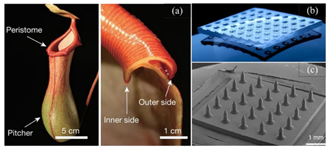
The microstructured functional surface refers to the structural surface endowed with special functions such as transforming physical, chemical, and optical properties. Its characteristic size is generally at the micron level (10–100 μm), with a high aspect ratio, and the surface is a geometric shape of micro topology [1,2]. Some common microstructural functional surfaces are shown in Figure 1.
In recent years, microstructured functional surfaces have been widely used in electronics, information techniques, aerospace, optics, biomedicine, and other fields due to their excellent application performance [3,4]. For example, Fresnel lenses for photovoltaic systems [5,6,7] and microfluidic chips for biomedical detection [8,9] and other microstructural functional surface products have shown their huge market potential. With the application development of microstructured functional surface components, the application of complex optical curved surface components with microstructured functional surfaces is more and more extensive. At the same time, the quality of its surface directly affects the performance of the products. As a result, the shape, precision, material, and surface quality put forward higher and higher requirements. However, due to the particularity of the structure and scale of the microstructured functional surface itself, it also faces new challenges in various manufacturing processes such as machining methods and equipment [10,11,12,13].
To realize micro- or nano-scale ultra-precision machining of microstructural functional surfaces, various unconventional ultra-precision manufacturing methods which are innovative from traditional machining methods have been reported constantly [14]. Under the popularization applications of micro-electro-mechanical systems (MEMS) [15], the surface processing technique of silicon parts develops rapidly and vigorously. (1) Anisotropic etching and electroplating are the main means. However, high-quality and rapid etching rates are a pair of contradictory propositions. What is more, etching requires higher etching conditions [16,17], surface properties depend on the plating process conditions [18], the calculations are complicated, etc. (2) Lithography, used in MEMS, is capable of producing features in micron and submicron sizes. However, such technologies are primarily used to produce 2D and 2.5D structures. They are limited in the range of materials that can be processed. These processing techniques of MEMS cannot meet the demand for miniaturized products and components that require 3D and high aspect ratio features, corrosion resistance environments, and enhanced micro drive. Given this, to produce micro components with a cost-effective and wide geometrical range at the microscopic and nanoscales, new complementary micromanufacturing technologies need to be developed [19].
Figure 1. Common microstructural functional surfaces. (a) Bionic functional surface (Pitcher plant) Reprinted with permission from Ref. [20]. Copyright 2016 Springer Nature. (b) The surface of the microcolumn array [21]. (c) The surface of microcone array [22].
Lubricants 10 00237 g001
With the machining technique development of microstructure functional surfaces, additive manufacturing and new machining methods using external energy fields have been popularized, which make up for the shortcomings of traditional machining methods. Fine machining of 60 nm local structure of 10 μm scale products can be achieved by 3D printing [23]. With the aid of three-dimensional ultrasonic vibration, the unique composite microstructure can be fabricated with picometer-level resolution [24]. At the same time, to get rid of the dependence on rigid tools, flexible noncontact polishing tools represented by improved magnetic fluid composited processing have also been developed. Nanoscale surface quality and shape accuracy have been achieved in the processing of optical components such as BK7 glass and fused quartz glass [25,26]. In addition, various processing methods that do not depend on tools are also presented in different processing objects or fields [27,28,29].
There are still some problems to be considered in the ultra-precision machining of microstructural functional surfaces by these methods. On the one hand, the surface has a large depth–width ratio, so the machining accuracy of each surface of the local microstructure unit cannot be well taken into consideration, which directly affects the performance of the products. On the other hand, while pursuing high surface accuracy, local micro-features cannot be well maintained, and the perfect balance point has not been found. What is more, specific processing methods, often used for specific products or structures, lack a certain universality.
The MJP technique proposed by QED Company has been proven by commercial applications due to its advantages of automatic adaptation to local surface polishing, stable removal of features, lack of sensitivity to machining distance, and a wide range of tractable materials. It can better realize the industrial finishing of microstructural functional surface components [30,31,32].
One promising approach for erosion-based fine finishing, with the objective of a high material removal rate and low surface roughness, is to apply a slurry jet with a high particle concentration but low kinetic energy. This allows a large number of particles to participate in material removal [30,31]. MJP is a typical example of this approach, using a high particle concentration slurry (MR fluid) for fine polishing of optical glass [32,33]. An important feature of an MR fluid jet is its collimated jet stream. Whereas a common water-based slurry jet becomes disturbed by the surrounding air and spreads out as it travels, the MR fluid jet from a nozzle is highly collimated and stable during traveling, until it impinges upon a workpiece. This behavior is caused by the application of a strong magnetic field at the nozzle exit that causes an instantaneous increase in the fluid viscosity. The MR fluid jet results in predictable and consistent material removal spots on a workpiece surface, and therefore it can be used to correct the surface shape of a high precision optical element, following estimation of the quantity of material to be removed [34]. Due to insensitivity to the offset distance, this technique may be valuable in finishing complex shapes, especially those with steep concaves and parts with a variety of cavities.
This paper firstly reviews the machining principle and method of the MJP machining technique and then makes a comprehensive analysis of the aspects of device improvement, process optimization, removal mechanism exploration, etc., to provide a better reference for the ultra-precision machining of microstructural functional surfaces.

2. Machining Mechanism of MJP Polishing Technique

Compared to traditional polishing techniques (such as chemical mechanical polishing) [35,36,37], MJP can be applied to complex surfaces without any special shaped tool. With the introduction of MJP, the high precision and difficult machining problems of the conformal, steep concave, ladder, and free-form surfaces have been solved, and it also has great advantages in the finishing process of the 3D structure [38]. MJP generates a stable, relatively high-speed, and low-viscosity jet beam through an external magnetic field, which solves the problem that the jet fluid in abrasive water jet polishing loses coherence when it leaves the nozzle, and makes the MR fluid remain highly collinear and stable before hitting the workpiece surface [39,40,41,42].

2.1. Principle of MJP

The typical magnetorheological jet polishing process is illustrated in Figure 2. Abrasive particles mixed with micron grade of MRF through mechanical mixing evenly in the container, and after the power system polish fluid is pumped through an installed inside the excitation coil made of ferromagnetic materials formed in the nozzle jet, the local stability of the axial magnetic field hardens the magnetorheological fluid jet polishing workpiece surfaces to a certain distance. The initial disturbance during jet ejection is eliminated by the applied magnetic field, and the workpiece is polished uniformly. After leaving the magnetic field, the magnetorheological fluid quickly returns to the shape of fluid, is filtered by the recovery device, and re-enters the device for recycling [43,44]. The workpiece is mounted on a multi-axis CNC spindle that can rotate and move in a straight line, and the nozzle and solenoid can be mounted on a workbench that moves in one dimension relative to the workpiece to adjust the incident angle of the jet fluid. In the process of processing, the viscosity of MR fluid can be controlled by magnetic field adjustment to control the shear force of material removal, to achieve the expected amount of removal [45].

2.2. Materials Removal Mechanism

Different from the known abrasive water jet (AWJ) polishing methods [47], material removal in MJP depends on the kinetic energy of impact particles, and material removal is achieved by the radial diffusion of jet fluid on the surface to be polished. This fluid flow generates enough surface stress to provide a material removal mechanism [48].
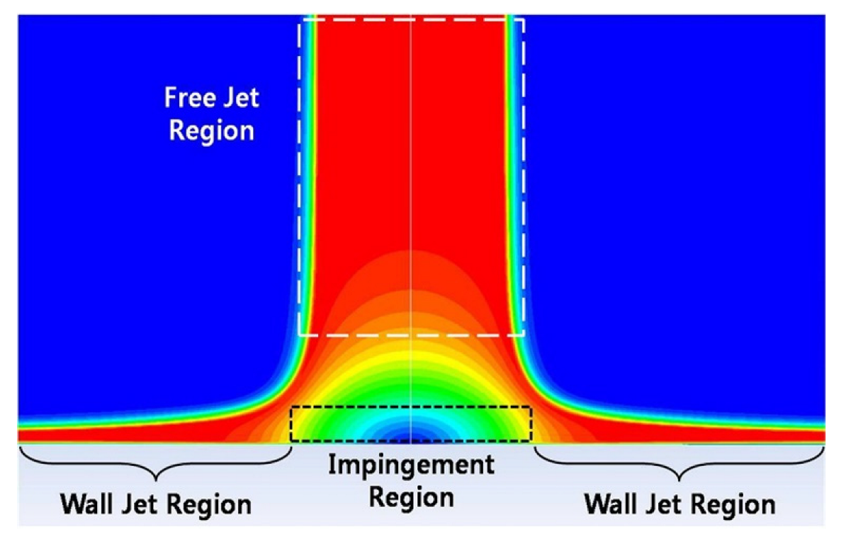
MR fluid is ejected through the nozzle and incident on the workpiece wall to produce impinging jet flow, which then flows to both sides. The whole injection process can be divided into three regions, namely the free jet region, the impact region, and the wall jet region, as shown in Figure 3.
During the polishing process, the MR fluid undergoes impact and wall flow processes from the time the jet comes into contact with the workpiece until it leaves the workpiece. The initial momentum and energy of the fluid jet impacts are not sufficient to damage the material, but these impacts positively affect the material removal results, setting the stage for subsequent impacts and subsequent material removal. After the accumulation of multiple impact processes, the material in the affected area becomes fatigued and relaxed, and the fracture toughness (KIC) of the material subsequently decreases. At this point, the pressure provided by the abrasive particles can reach the new fracture limit (Pcr) of the material and thus the surface material can be removed. The impact process can be described as the effect of the fluid on the surface normal pressure, the distribution of which is a predictable function of position and does not vary with time. On the surface of the workpiece in the impact region, the material forms fragments and flakes off, and the material removal is random. Equation (1) gives the formula for calculating the critical load for the material fracture through the fracture mechanics theory. Zhang [50] performed calculations and concluded that the abrasive jet impact process is not sufficient to separate particles from the workpiece [51]:
P c r = 2 × 10 5 ( K I C 4 / H N 3 )
where Pcr is the critical load required to fracture the material, KIC is the fracture toughness of the workpiece material, and HN is the hardness of the material.
The removal mechanism of the MJP technique has two processes. Firstly, the magnetic jet beam impacts the workpiece surface and the jet liquid diffuses after reaching the workpiece surface, and then the material is removed by using velocity, pressure, and shear force [50]. In the process of efflux liquid contacting the workpiece and fluid leaving the workpiece, the fluid experiences the impact process and wall flow process. According to the CFD simulation results, shock and shear effects exist in the entire removal area.
Because of the different distribution values of pressure and velocity, the proportion of the two active forms in different positions is also different. For the convenience of analysis, the area dominated by shear action is called the wall jet area, and the area dominated by impact action is called the impact area.
The specific action process is as follows:
(1)
In the wall jet area, the tensile strength of the material is much smaller than the compressive strength of the material. Therefore, when the fluid flows on the wall, the impact angle of the particles along the wall to the workpiece surface decreases from the center, and the radial velocity rapidly increases to the maximum and then decreases gradually along the streamline. Low impact angle and high radial velocity can produce maximum micro-cutting efficiency, resulting in a W-shaped material removal profile [52,53]. From the microscopic removal process, when the fluid flows over the workpiece surface, as shown in Figure 4a,b, the peak of the rough surface is first contacted by the abrasive, as shown in Figure 4c. Abrasive contact with the bottom of the rough surface is a very low probability; therefore, the peak is removed first and then layer by layer cutting, which is the main reason for the roughness reduction after polishing.
(2)
In the central area, a small amount of material is removed when the workpiece surface is impacted by the jet fluid. The impact process can be described as the effect of the fluid on the normal pressure of the surface, the distribution of which is a predictable function of position and does not vary with time. Under impact, the surface of the workpiece forms fragments and peels off, and the removal of material is random. In the macroscopic expression, a small amount of material can be removed, which is why the removal rate of the impact zone is not zero in the actual polishing results. This random removal process of the workpiece surface has a low removal efficiency but has a great impact on the roughness [53].
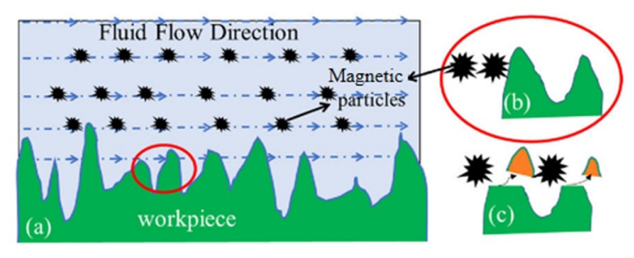
Figure 4. Polishing zone material removal model Reprinted with permission from Ref. [53]. Copyright 2020 Applied Optics. (a) Fluid flow across the workpiece surface; (b) Magnetic particles-Workpiece Contact; (c) Cutting surface peck.
Lubricants 10 00237 g004

2.3. Rheological Characteristics Analysis of MR Fluid

Magnetorheological (MR) fluids invented by Rabinow [54] in the late 1940s belong to a class of smart controllable materials whose rheological behavior can be externally manipulated through the application of certain energy fields. In the absence of a magnetic field, ideal MR fluid exhibits Newtonian fluid behavior; under the application of an external magnetic field, it exhibits magnetorheological properties [55]. Figure 5 shows the schematic diagram of the magnetorheological effect. The magnetic field makes the magnetorheological fluid rapidly transform into a Bingham viscoplastic fluid with high viscosity and low fluidity within milliseconds [56]. After the magnetic field is removed, the magnetorheological fluid returns to its initial viscosity [57]. The change of apparent viscosity of MR fluid with magnetic field strength is continuous and stepless, which is called the magnetorheological effect.
The following is a research results overview of the rheological properties of MHD under a magnetic field. Kuzhir [59] studied the longitudinal and transverse magnetic field effects when magnetic flow variants passed through axisymmetrical holes. Their research results showed that the longitudinal magnetic field effect was mainly manifested as the significant increase of the slope of the pressure flow curve, but there was no obvious yield stress, and the transverse magnetic field did not affect the pressure drop. Kciuk [60] analyzed the fluidity of the internal structure of MR containing carbonyl iron (CI) particles under the control of the external magnetic field and showed that the dynamic viscosity of MH could change rapidly and reversibly. Zhang [61] studied the axis-symmetric annular gap flow of magnetic flow variants under different excitation currents and shear rates: when the excitation current increases, the rigid flow zone expands rapidly; the shear velocity also has a great influence on the size of the rigid flow zone, but the influence on the viscosity of the magnetic flow variant is weak.
The temperature change also affects the physical structure of MR fluid obviously, which affects its stress and viscosity. Andreas [62] from Germany analyzed the heat source of the magnetorheological machining unit with an infrared camera and found that the stirring motor led to the heating of the magnetorheological fluid in the fluid regulator, thus affecting the processing quality.
The deep excavation of the rheological characteristics of MR fluid is conducive to exploring the unique advantages of its removal mechanism, further optimizing its processing technique, and promoting the fundamental reform of its machining accuracy and efficiency.

2.4. Material Removal Model

Compared with the AWJ technique, the MJP technique reflects greater advantages in part polishing, such as significantly higher polishing efficiency and polishing quality. In terms of workpiece surface improvement, the MJP technique has greater advantages, mainly in the smoothness and controllability of magnetic abrasives. Polished surface accuracy is high, and as such roughness can be controlled within a few nanometers, surface tissue damage is small and almost does not affect its function such as light guide performance, which is especially suitable for the polishing of hard and brittle materials such as optical parts.
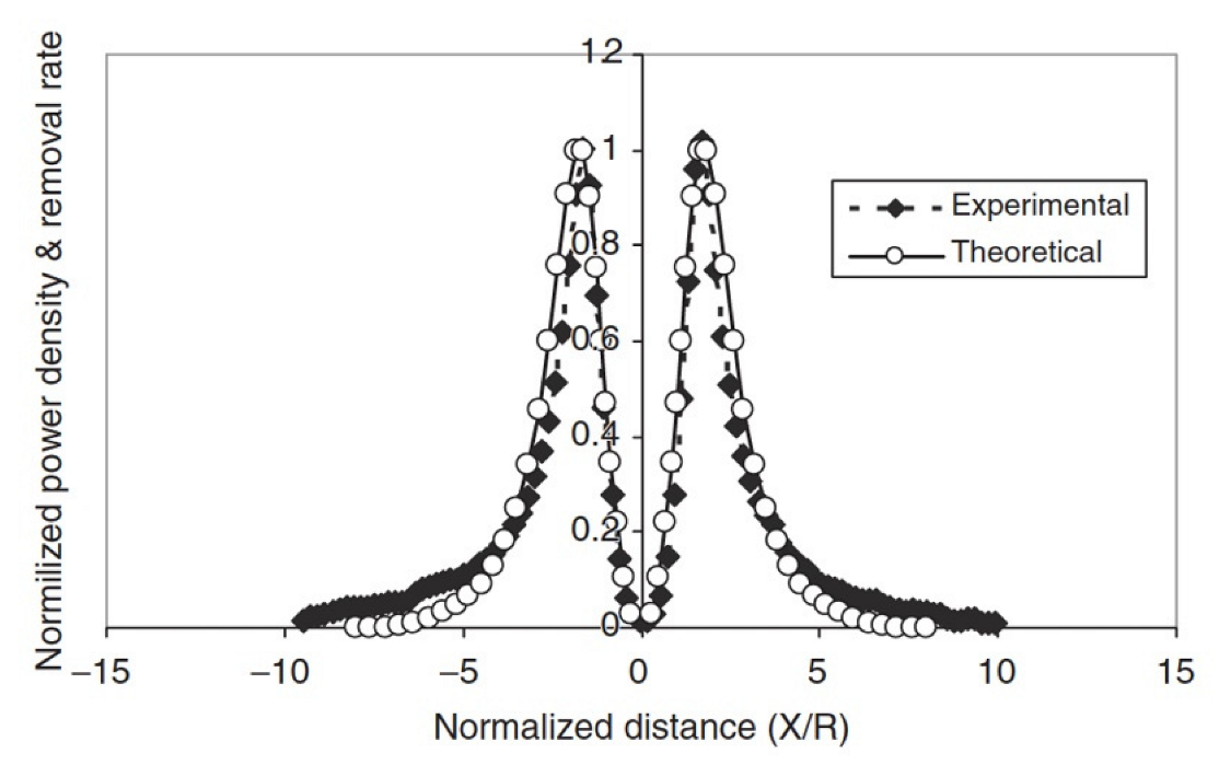
Zhang [63] analyzed the material removal mechanism of MJP based on CFD and obtained the relationship between material removal rate and power W as shown in Equation (2). They studied the shear force and work done on the workpiece surface by radial extended flow of MJP in the removal model. It is possible to conclude that the main force of workpiece material removal is the shear force generated by the radial expansion flow of the magnetorheological fluid jet on the surface of the workpiece. The removal profile of the polishing area can be predicted by CFD. However, this model only considers the tangential effect of pressure but ignores the impact effect of polishing fluid, which leads to the error between the contour obtained by the test and the removal model. Lee [64] studied the stress-energy wave generated by a magnetic jet and obtained the expression of polishing parameters. Kordonski [65] further analyzed the energy generated by laminar flow and concluded that the removal rate of workpiece material was proportional to the product of shear stress and fluid velocity and obtained the removal model as shown in Equation (3). Different influence parameters were used to polish the workpiece, and the dimensional contours of experimental removal and theoretical removal were obtained as shown in Figure 6, which have a good correlation.
M R R = k τ f U = k W f
M R R = K | τ x V |
where k is quasi-Preston constant; τ and τx are surface shear stresses; f is friction coefficient; V is the vector fluid velocity.
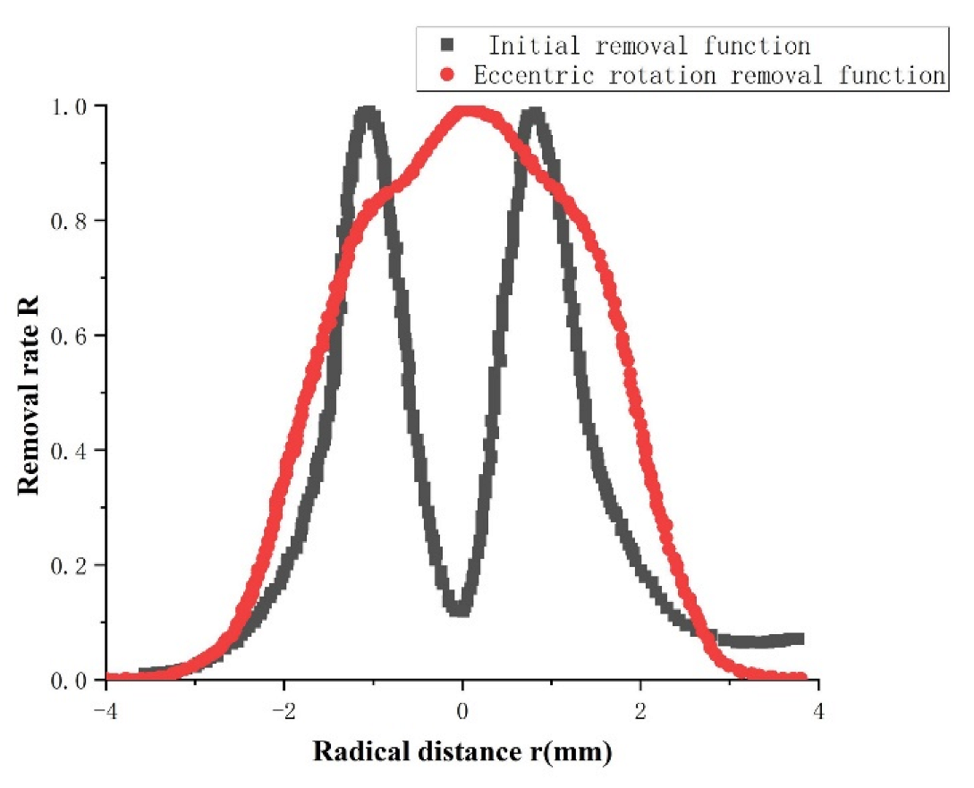
Based on the research of Zhang [62], Dai [58,66] modified the removal model of workpiece materials by the eccentric rotating polishing head. The modified removal model can effectively avoid high-frequency errors caused by the annular contour in the process of workpiece polishing and can better modify the workpiece surface. The research shows that the center pit can be eliminated and a removal model similar to the Gaussian shape can be obtained by rotating the annular polishing area with the minimum removal amount around an eccentric axis with a lateral offset distance of 1 mm, as shown in Figure 7. The optimized removal function can greatly reduce the residual error and avoid the generation of surface ripples of the workpiece [26].
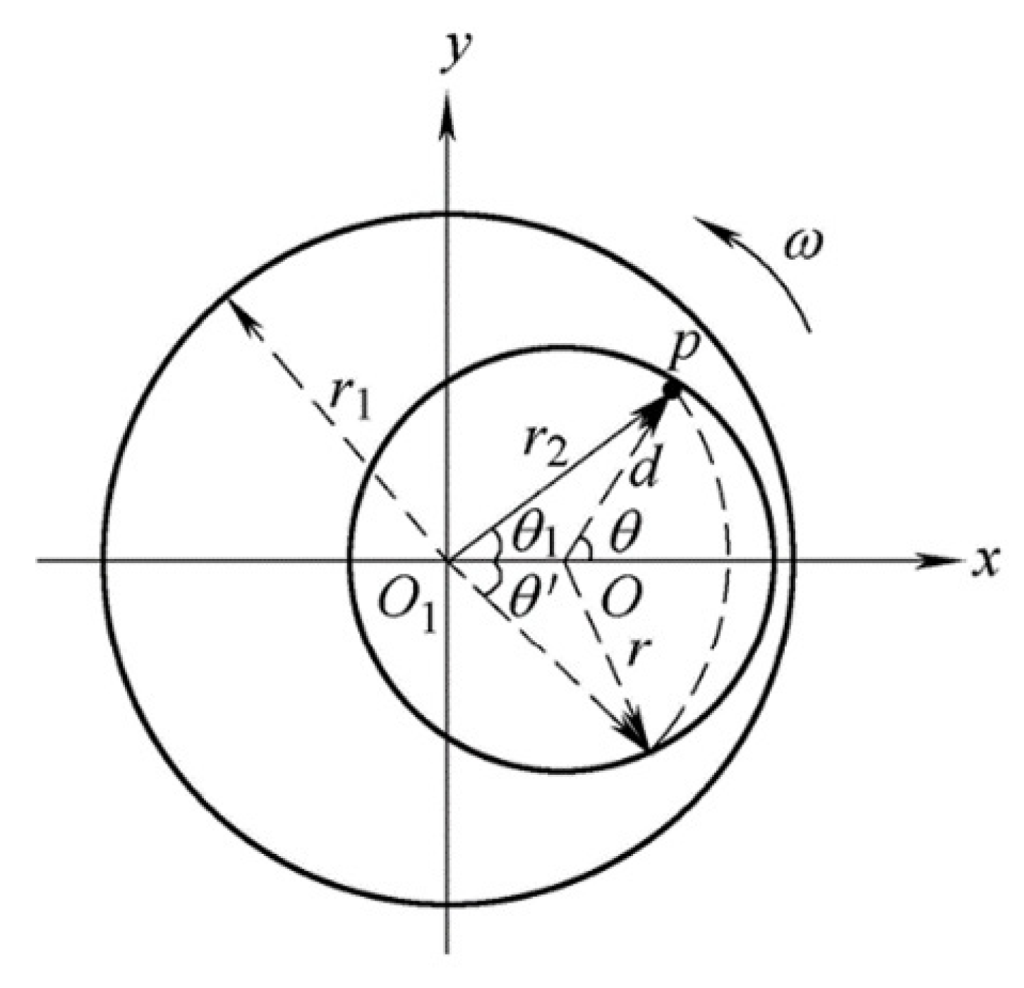
Cheng [67] conducted further research on jet polishing with eccentric rotation and obtained a reasonable eccentric distance through simulation and testing. Its eccentric rotational motion is shown in Figure 8. The removal model obtained at this eccentric distance was closer to a Gaussian shape than Dai [58]. Based on fluid impact dynamics theory, an eccentric rotation motion removal function is derived, as shown in Equation (4). The trend factor F (the closer it is to 1, the more it tends to a Gaussian curve) is set to study the influence of the eccentric distance on material removal in the removal function. The schematic diagram of its movement mode is shown in Figure 8. The best removal distribution is obtained when the eccentricity is 0.8 L (L ≈ 0.7 mm). The experimental results show that when the eccentricity distance is about 0.56 mm, the trend factor F = 0.969, and the Gauss-like material removal curve can be obtained, which can better achieve the controlled material removal of the workpiece.
R 1 ( r 2 ) = 1 ω θ ¯ θ R ( d , θ ) d θ 1 { θ ¯ = arccos { [ r 2 2 + e 2 r 2 ( 2 r 2 e ) ] r e c t [ ( r 2 r ) ( 2 e ) ] s t e p ( r e r 2 ) } d = ( e 2 + r 2 2 e r 2 cos θ 1 ) 1 2 0 r 2 r + e θ = arcsin ( r 2 sin θ 1 d )
where e is the eccentricity distance; r is the radius of the eccentric circle; r1 is the radius of the polishing area; r2 is the distance between the center point of the polishing area and a point on the eccentric circle; θ is the angle between OP and X-axis; θ1 is the angle between O1P and the X-axis.
Yang [68] used the discrete phase model (DPM) in CFD to analyze the removal model of different abrasive concentrations, as shown in Equation (5). Polishing experiments discussed the influence of pressure, shear force, and polishing abrasive particle velocity on the removal function in the model. The results show that 45° oblique injections can produce a polishing tool influence function similar to bevel cutting, and the RMS of the section profile after polishing decreases from 10.5 nm to 1.4 nm without any new edge effects [69].
R ( x , y ) = d z d t = Γ k i = 1 n P | S Δ v |
where Γ is the relative function of pressure P and shear force S; K is the coefficient related to the processing parameters; Δv is the change of shear velocity of a single abrasive particle after the collision.
Based on the wear model and particle flow theory, Kim [34,70,71,72] derived the material removal function as shown in Equations (6)–(8). The experimental results demonstrate that at the jet velocity of 10 m/s, the friction stress is dominant in the wall sub-layer, and the material removal rate is proportional to the square of the wall shear rate. When the jet velocity increases to 30 m/s, the material removal rate is proportionate to the cubic power of the wall shear rate.
N = λ 0.5 ρ P D 2 γ η
d z d t = C 1 H ρ P λ 2 D 3 γ 3 N < 100
d z d t = C 2 H ρ P λ 1.5 η D γ 2 N > 100
where λ is the linear concentration of particles; ρp is the particle density; and η is the liquid viscosity, where dz/dt is the material removal rate, D is the particle diameter, C1 and C2 are non-dimensional coefficients of machinability, N is the dimensionless Bagnold Number, and γ is the shear rate.

3. MJP Processing System

The MJP polishing system is mainly composed of a nozzle, electromagnet module, power system, recovery system, and moving system. In the MJP polishing system, the characteristics of the polishing fluid injected into the magnetized nozzle have a significant impact on the material removal rate and surface roughness. In the miniature nozzle, the flow rate of the polishing fluid increases significantly with the decrease of the inner diameter [63]. The design of the nozzle and electromagnetic module is an important consideration to produce uniform polishing spots.

3.1. Design and Analysis of Magnetic Field

Zhang [50,73] designed the magnetic field in MJP, analyzed the influence of the head shape of the ferromagnetic nozzle on the magnetic fields, and simulated the influence of the structure shape on the spatial characteristics of the magnetic field through ANSYS. The simulation results show that the volume and weight of the solenoid must be taken into account to drive the nozzle to rotate in the polishing process. Therefore, a slightly smaller G value (Fabry coefficient) can be chosen to avoid excessive volume, and the resulting reduced magnetic field power can be compensated by appropriately increasing the power.
Chen [74] used ANSYS software to simulate and analyze the materials and structure of the electromagnetic field magnetic shielding system of magnetic liquid jet polishing and abrasive tools and designed the magnetic shielding system based on the results. The simulation and experimental results show that the double-layer shielding structure with high conductive magnetic material with low reluctance characteristics can improve the shielding efficiency, reduce the “magnetic leakage” and effectively prevent the workpiece from being magnetized.
Based on the electromagnetic theory, Yang [69] proposed the ideal distribution characteristics of the magnetic field inside the structure and optimized the key parameters in the structure of the integrated magnetorheological jet polishing (IMJP) tool.
Hou et al. [75,76] numerically simulated the excitation coil magnetic field intensity distribution with Comsol software and focused on the distribution of the flow field inside the form. The simulation results showed that the excitation coil excitation of magnetic flux density in the center of the field area is higher and increases with the increase of the excitation current (when the excitation current I = 2.2 A, and the abrasive jet beam won the best focusing effect in the nozzle exit).

3.2. Optimization of the Nozzle Structure

The jet system is an important part of the MJP system, which converts the pressure energy of MR fluid into kinetic energy through the nozzle to form a high-energy beam. The structure of the nozzle can greatly affect the flow and dynamic characteristics of the jet beam, the removal rate of the workpiece, and the surface roughness of the workpiece [52,77].
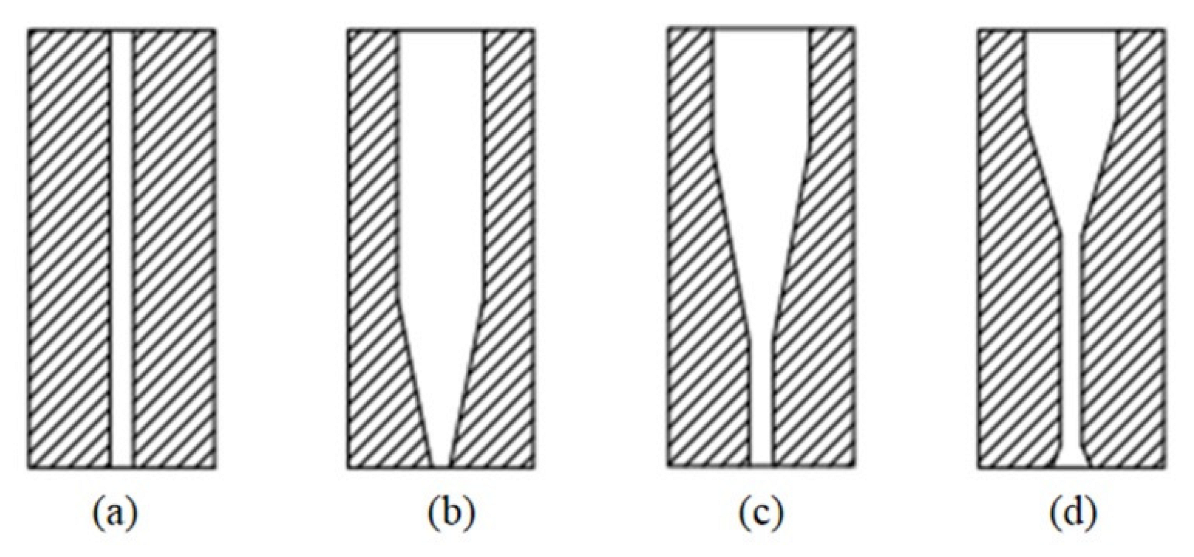
Shi [78] studied the effect of jet characteristics on jet polishing and put forward the design principle of the jet polishing nozzle by contrastive analysis of four types of nozzle jet characteristics (cylinder, cone, cone column, and spread of cone column), as shown in Figure 9. The results showed that the cone column type nozzle exit velocity distribution is uniform, the distribution of outlet and wall turbulence intensity is relatively small, and the distribution of outlet abrasive concentration and wall concentration is the most uniform.
Wang [79,80] invented a new efficient polishing multi-jet polishing process and tool, which used a specially designed nozzle, as illustrated in Figure 10. The distribution of the nozzle has many rules, and the number of holes can be a few to several hundred, and each hole can emit a high-energy fluid jet, can be efficient in large-scale surface or lens array surface polishing, and solve the traditional fluid jetting projectile polishing on the surface of the lower removal rate and the medium size limit to improve the material removal rate.

3.3. Circulating Stirring System

In the circulating stirring system developed by the QED Company [81,82], the recovered liquid flows into the stirring device by itself. However, the experimental results show that the recovered liquid often remains at the bottom of the container due to the poor fluidity of abrasive iron powder, so it is difficult to flow into the stirring device by itself. Then, with the increase in polishing time, the liquid composition changes, and it is difficult to keep the removal function stable.
Given this, Li [83] developed a magnetic jet circulation system. The circulating system adopts the method of eccentric funnel to carry the magnetic jet fluid, and the eccentric funnel and the magnetic field component or the center of the nozzle are eccentric. Stir in an eccentric funnel to join components and a lateral jet in load on the side of the eccentric funnel magnetic jet liquid gas or water, or a special magnetic liquid jet can not only realize the mixing of liquid and can realize the eccentric funnel wall scour, bubbled into special gases can maintain the performance of magnetic liquid jet, but a lateral jet of water can realize auxiliary magnetic liquid jet cleaning. In addition, the water cooling channel, pressure detection, temperature detection, and other auxiliary parameters are added to the device to realize the parametric control of the circulation system and then realize the stable circulation of magnetic jet fluid.

3.4. On–Line Monitoring of MR Fluid

During processing, factors such as precipitation, evaporation of liquid carriers, oxidation, and agglomeration of magnetic particles may cause changes in the properties of the MR fluids. Or even failure of the entire system. Of these, the most vulnerable include those without seals, particularly those using water-based MR fluids. The stability of the material removal function mainly depends on the stability of MR polishing fluid, so the monitoring of MR fluid is very important [37,84,85,86].
Kordonski [87] introduced two different new methods for online measurement of magnetic fluid permeability. These two methods use different sensors to monitor MR fluid, and both of them can provide satisfactory measurement accuracy. The experimental results demonstrate that these two methods are effective in monitoring the stability of MR fluid by concentration track.

3.5. The Special MJP System

In recent years, with the deepening of the research and application of the MJP technique in the field of ultra-precision manufacturing, relevant scholars and institutions have developed corresponding MJP systems.
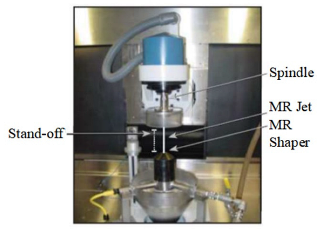
As a pioneer of the MJP technique, the QED Company has developed the processing device as shown in Figure 11. The unit is equipped with a five-axis CNC platform and polishing control software developed by QED. The delivery system includes a mixing vessel for dispersing solids in the MR fluid, a pump, a device for maintaining the temperature and viscosity of the liquid as well as pressure and a flow sensor for monitoring the condition of the system. The magnetorheological generator is located below the spindle of the CNC platform and uses the magnetorheological properties and magnetic field to stabilize the magnetorheological jet beam. In the presence of a magnetic field, the collimated jet beam is directed vertically upward toward the workpiece held by the spindle. The magnetorheological fluid recovery device accommodates, collects, and recycles the magnetorheological fluid after it hits the surface of the part [33,88].
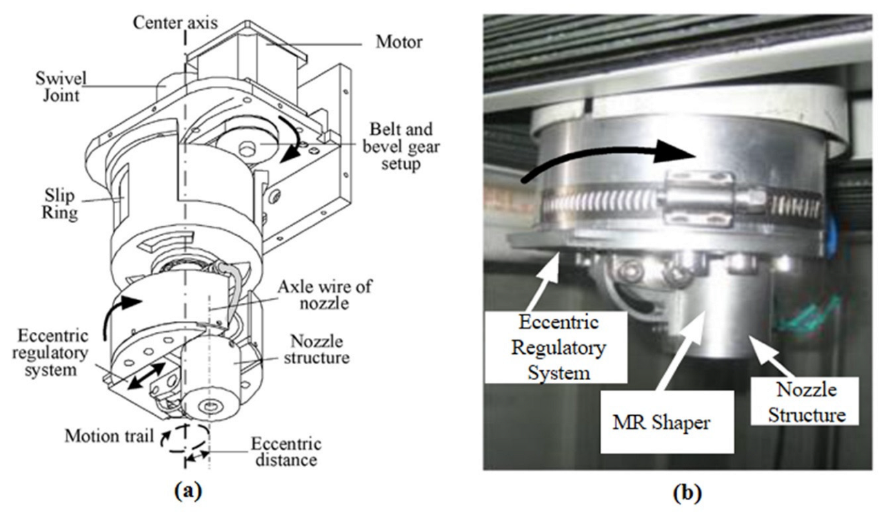
Cheng [67] designed an MJP tool with eccentric rotation motion to meet the special needs of small-scale discontinuous optical surface manufacturing. As shown in Figure 12, eccentric rotation can be achieved by using an eccentric adjustment system, rotary joint, and slip ring. In the polishing process, the eccentricity is firstly determined and adjusted according to the diameter of the nozzle. Then, the polishing tool is precisely controlled for polishing. The device can make the center of the circular trajectory of the jet liquid on the central axis. In millimeter scale machining experiments, the roughness of the workpiece can be processed to Ra = 4.86 nm in a short time, which proves the reliability of the device design and the remarkable roughness convergence ability of the polishing tool for small and complex structures.
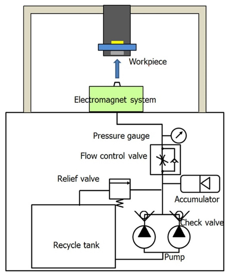
Lee [49,89,90] developed a micro MR fluid jet polishing device, as shown in Figure 13. (1) Two parallel diaphragm pumps are used as the power device. The pressure is 15 bar, and the pressure can reach more than 20 bar through the change of the pressure difference between the inlet and outlet. (2) Check valves, pressure-reducing valves, and accumulators are installed in the hydraulic system to avoid pulse motion caused by turbulence. (3) The electromagnet module in the system can generate a magnetic field strength of 1500 G under A current of 1.5 A. (4) The high-pressure nozzle and electromagnetic module are installed on the precision moving table and various shapes can be polished by adjusting the feed speed and chuck module. In experiments, the device produced stable, uniform, and predictable polishing points and had a good effect on the removal of burrs in the micropyramid pattern, a typical microvertebrate structure.
Hou [91] developed a magnetic field-assisted AWJ machining device as shown in Figure 14: (1) The magnetic field strength can be adjusted by the excitation current flowing through the coil; (2) the device is equipped with a jet impact force measurement system, which can realize real-time acquisition and analysis of impact force signals so as to predict the amount of material removal.
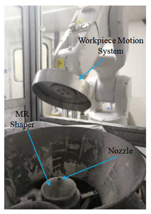
Hai [51] developed an MJP device as shown in Figure 15. The device combines the problems of some scholars in the polishing process and makes targeted improvements to the workpiece’s motion actuator, MR fluid circulation system, power system, magnetic field generating device, etc., so that the MJP machining device has a higher degree of integration.

4. Study on MJP Processing Technique

To verify the material removal ability and surface quality of the MJP technique, some scholars have conducted in-depth research on the magnetorheological finishing experiments of different materials. Through polishing experiments, the effects of the properties of MR fluid, material removal ability, and machining technique on the surface quality of the workpiece were explored, which provided reliable guidance for subsequent research.

4.1. The Jet Direction

Downward injection of the MR fluid is generally used for large and heavy workpieces and is not suitable for polishing surfaces with large concave degrees. The reason is that the magnetorheological fluid is deposited in the low concave area during the downward injection, which hinders the effect of the jet on the workpiece surface and reduces the polishing ability or even fails to be polished. When spraying upward, the deposition of polishing fluid can be avoided so that the magnetorheological fluid has cooling time, and the influence of temperature on the workpiece and the chemical reaction at a high temperature can be avoided. However, the clamping mechanism of the machine tool is required to have high installation accuracy to avoid large deformations [50].

4.2. Effect of Incident Angle on Material Removal Rate

According to the impact angle (the angle between jet and impact surface), jet polishing can be divided into vertical jet polishing and oblique impact jet polishing. Vertical jet polishing is a process in which the jet impinges vertically on the workpiece wall. Due to the axisymmetric nature of the jet, the shape of the workpiece polishing surface is symmetrical and circular. For oblique impinging jet polishing, the jet characteristics are more complex than those of vertical impinging jet polishing. The impinging pressure and wall velocity are asymmetrically distributed, the thickness distribution around the jet is also different, and the abrasive distribution of materials will appear different due to the different impact angles. Studies have shown that oblique incident polishing has good results in the treatment of edge effects [51].
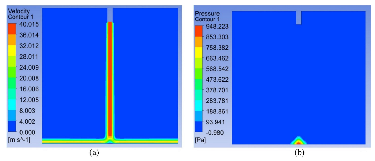
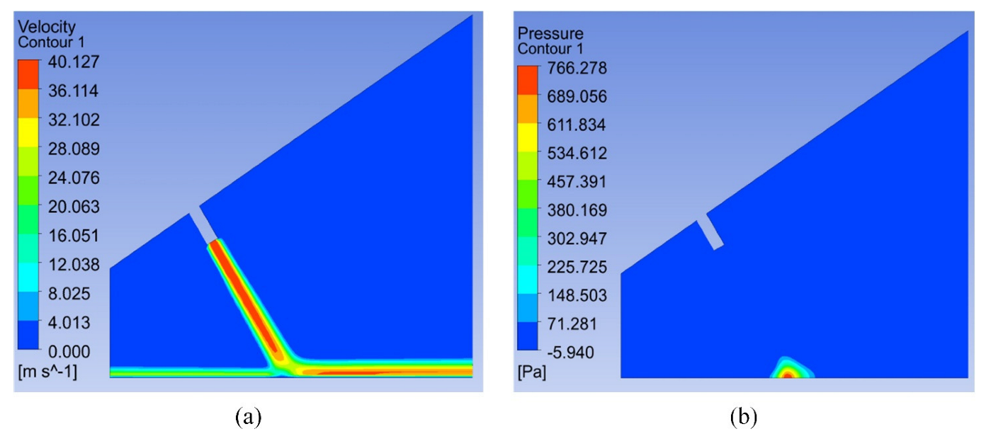
To study the effect of the impact angle on the characteristics and polishing effect of impinging jets, computational fluid dynamics (CFD) was used to analyze the jet polishing process with different impact angles [53,92,93,94]. For the flow mode of the magnetic jet, it should meet the axisymmetric distribution structure. The three-dimensional model and the axisymmetric two-dimensional model are similar in the form of results and data distribution. To simplify the calculation model, two-dimensional jet polishing models with impact angles of 90° and 60° were constructed, respectively. Related parameters are shown in Table 1.
The comparative analysis shows that:
(1)
The velocity distribution cloud diagram and pressure distribution cloud diagram of vertical incidence are shown in Figure 16. ① After reaching the surface of the workpiece, the velocity in the center area of the fluid decreases to 0. In the process of diffusion, as a form of shear flow with a large concentration, the liquid does not spatter in the X direction but always flows on the surface of the workpiece. This is different from the flow state in abrasive jet polishing. ② During diffusion, the velocity rapidly increases to the maximum and then decreases due to the presence of shear force. However, the effective polishing area is only less than 20 mm, and in such a small area, the velocity approximately maintains the maximum value. The pressure action area is small and the distribution form is more symmetrical. In summary, the pressure on the workpiece surface presents a circular distribution. The center of the circle is the central area of the magnetic jet collision, and the diameter is about the distance of three to four nozzles. The pressure distribution form of the fluid on the workpiece is similar to the Gaussian shape distribution, and the pressure in the middle area is high and decreases in the radial direction [51].
(2)
The velocity distribution cloud diagram and pressure distribution cloud diagram for oblique incidence are shown in Figure 17. ① In terms of distribution form, the force on the workpiece surface is asymmetric; in terms of fluid flow, the incident angle is the obtuse angle, and the flow is larger. ② Of the removal effect on the workpiece surface, when the flow is larger, the speed is large, and the pressure is large, which leads to the result of a high removal rate. Due to the obtuse incidence removal function, the obtuse angle removal is going to be a little bit more efficient [51].
(3)
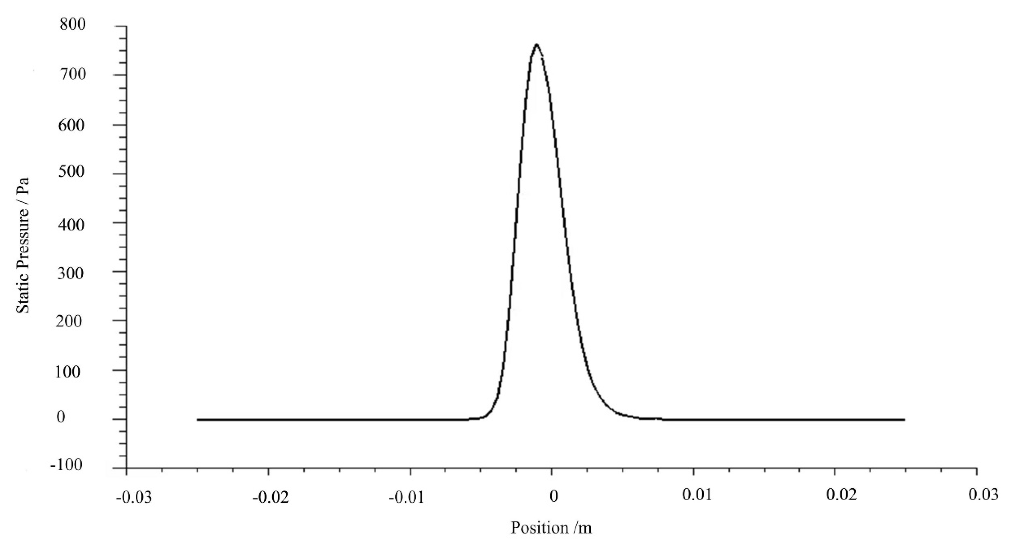
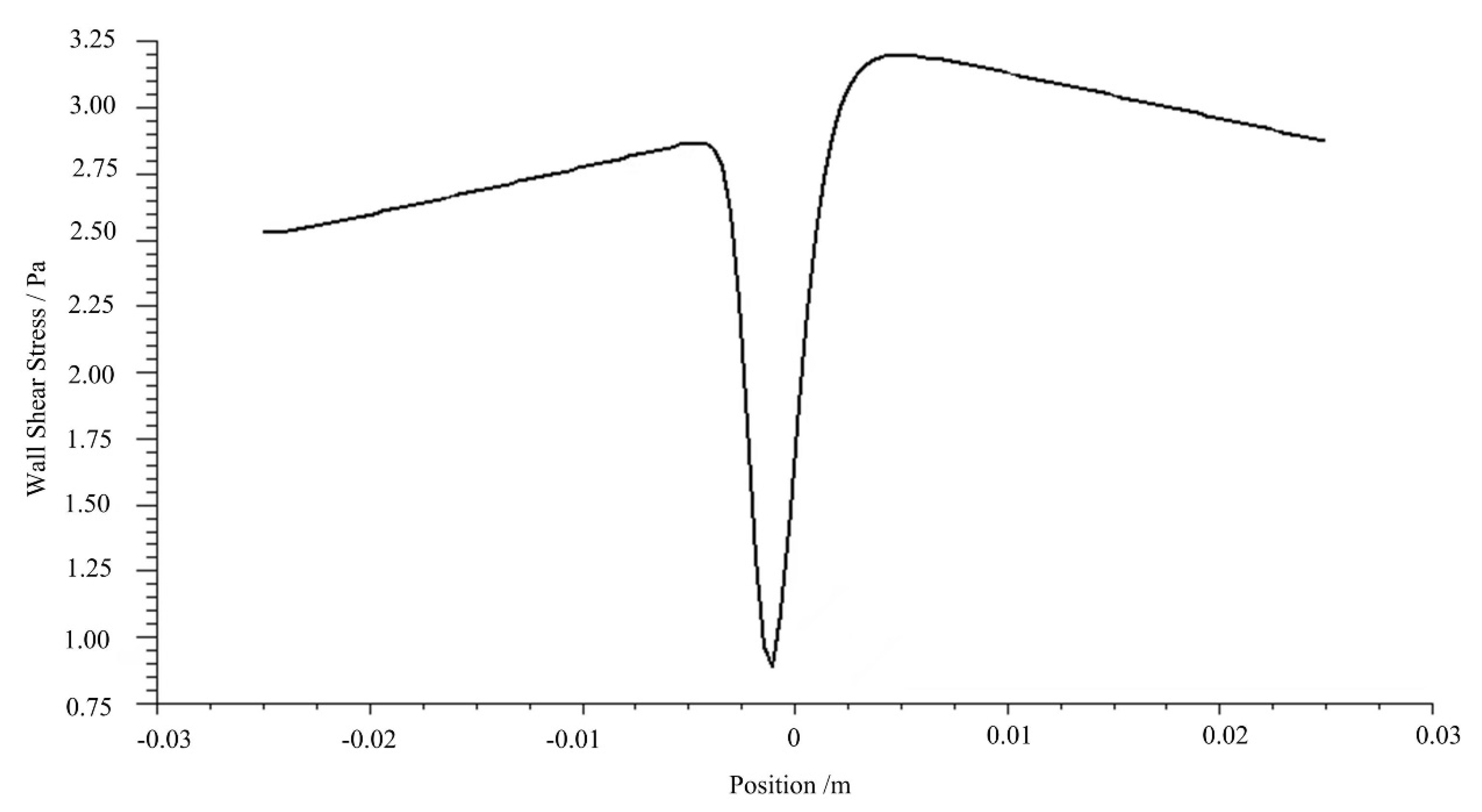
The positive pressure curve is analyzed, as shown in Figure 18. ① The pressure and shear force in the acute angle area changes faster. ② Compared with the distribution at normal incidence, the whole function shows a slanted Gaussian-like shape. The maximum pressure distribution is still in the corresponding position of the jet center. ③ The shear force form is very different from the vertical incidence, as shown in Figure 19. The asymmetric form is manifested to a large extent, and the shear force has a significant influence on the removal of the workpiece.

4.3. Relationship between Jet Velocity and Removal Rate

Kordonski [65] conducted experiments under the conditions that the jet diameter was 2.4 mm, and the jet velocity values were 15 m/s, 20 m/s, and 27 m/s, respectively. By analyzing the experimental results, it was concluded that the jet velocity and removal rate had a cubic relationship.
The experimental results show that the diameter of the removal function increases with the increase of the jet velocity. The effect of velocity on the peak removal rate and volume removal rate of the removal function is positively correlated. The research conjecture is that there is a quadratic relationship between jet velocity and removal rate [51].

4.4. Path Programming

Wang [95] realized the V-shaped removal function by controlling the trajectory spacing by taking advantage of the M-shaped removal function of the magnetic jets.
Li [96] significantly improved polishing accuracy by alternately iterating the trajectory automatically generated by contour error and the sub-aperture position mapping. The trajectory is generated automatically according to the contour error and is iterated in layers, which gives consideration to both efficiency and accuracy.

4.5. Effect of Processing Technique

According to different materials, the current technological progress of MJP machining is shown in Table 2. Polishing results show that the MJP technique is more appropriate for the precise finalization of complex forms. It was also established that high precision surfaces can be manufactured by MJP with a roughness of <1 nm and in a range of materials, including glasses, single crystals, advanced ceramics, and metals. This technique offers a versatile solution for conformal optic imaging systems [97].
Numerous experimental studies have shown that the jet velocity, angle of impact, jet pressure, nozzle diameters, machining time, and magnetic field strength mainly affect the processing effect of MJP.

5. Conclusions

Compared with the traditional surface finishing technique, the MJP technique has irreplaceable advantages in polishing the functional surface of the microstructure. Because of its non-contact processing, it can process the workpiece with a complex surface, and the shape accuracy is good, the surface accuracy is high, and the removal function is not interfered with by the distance between the tool and the workpiece, which can effectively avoid the mechanical interference and realize the ultra-smooth dressing of the surface of the complex cavity. The MJP technique is one of the most promising optical precision machining methods of the future. The MJP technique will continue to develop and improve in the process of improving the accuracy of ultra-precision machining, machining efficiency, and the development of MR fluids in the future and become the mainstream of ultra-precision machining methods and technologies.
However, as a polishing technique that has not yet been applied in engineering, it still has some shortcomings and needs further theoretical and technical research. (1) MJP uses magnetorheological fluid as a carrier for abrasive particles, which is more costly; (2) MJP is a small-tool polishing technique, so there will be medium and high-frequency error problems; (3) it is a technique with low machining efficiency, not suitable for machining large size workpieces; and (4) it has poor stability, and equipment requires frequent maintenance. In future research, the MJP technology should be continuously improved to address these problems in order to obtain better processing results in the field of ultra-precision machining.
In order to enhance the value of MJP, improvements in the following areas are required:
(1)
The stability and efficiency of the removal function need to be studied urgently. For large diameter or more complex surfaces, the processing cycle is often very long, needs longer continuous working time, better stability of magnetic jet fluid, and polishing equipment to meet the requirements of high certainty and high-efficiency polishing. To derive a more accurate material removal function, it is necessary to deeply study the properties of polishing fluid with rheological effect, to solve the problem of fluctuation of polishing fluid composition concentration and rheological properties during the polishing process, and to realize the stability and controllability of polishing fluid rheological properties such as viscosity and hardness by controlling the auxiliary field. Based on theoretical and simulation tests, we will further study the removal mechanism of workpiece materials and optimize the polishing fluid configuration and polishing parameters according to the physicochemical characteristics of different materials.
(2)
New techniques and new principles of magnetorheological jet polishing still need to be developed. At present, it is urgent to develop a composite machining method, such as one combined with ultrasonic vibration machining to solve the problem of the low removal rate and low machining efficiency of magnetic jet polishing.
(3)
Deterministic removal model for magnetorheological jet polishing needs to be established. The current research is based on the Preston equation, which divides the pressure on the workpiece into several parts, calculates them separately, and then superposes them. When the material removal model is established, it is simply considered from the two-dimensional direction, without the in-depth consideration of the model from the three-dimensional direction. It is necessary to adopt a reasonable magnetic jet hydrodynamic model to establish a universal and unified deterministic removal model system to adapt to the processing of various profiles.
(4)
The process needs to be modified and accurately controlled. Based on completely determining the removal function and the correction function, the algorithm relationship between the removal function and the correction function must be taken into account to control the various movements of the nozzle to achieve the removal of the determined quantity, and a reasonable algorithm of the material removal rate and dwell time should be adopted. To achieve high precision and surface integrity machining of product parts, in addition to accurate material removal functions/models, there is an urgent need to propose more accurate polishing removal dwell time algorithms and path planning functions to achieve the controllable removal of points, lines, and surfaces in order to improve the accuracy of workpiece detection during polishing, to effectively reflect the changes in workpiece surface morphology and material removal during the polishing process, and to accurately characterize the material removal distribution in the processing area.
(5)
The online inspection technique machining process needs to be improved. MJP machining workpiece surface measurement is currently mainly on the workpiece after processing offline detection, which will affect the efficiency of processing, automatic compensation accuracy, and workpiece surface quality to a certain extent. Therefore, the development of the MJP online detection and automatic compensation processing technique is also one of the key issues [100].

Author Contributions

Conceptualization, D.S. and R.W.; writing—original draft preparation, H.D.; manuscript revision, D.S., J.L. and X.Z. All authors have read and agreed to the published version of the manuscript.

Funding

This research was funded by Science and Technique Development Projects of Jilin Province (20210101073JC) and Science and Technique Research Project of Jilin Provincial Department of Education, grant number JJKH20210727KJ.

Data Availability Statement

Not applicable.

Conflicts of Interest

The authors declare no conflict of interest.

References

  1. Brinksmeier, E.; Gläbe, R.; Schönemann, L. Review on diamond-machining processes for the generation of functional surface structures. Cirp J. Manuf. Sci. Technol. 2012, 5, 1–7. [Google Scholar] [CrossRef]
  2. Evans, C.J.; Bryan, J.B. “Structured” “Textured” or “Engineered” surface. CIRP Ann. 1999, 48, 541–556. [Google Scholar] [CrossRef]
  3. Bruzzone, A.; Costa, H.; Lonardo, P.; Lucca, D. Advances in engineered surfaces for functional performance. CIRP Ann. 2008, 57, 750–769. [Google Scholar] [CrossRef]
  4. Zhang, S.; Zhou, Y.; Zhang, H.; Xiong, Z.; To, S. Advances in ultra-precision machining of micro-structured functional surfaces and their typical applications. Int. J. Mach. Tools Manuf. 2019, 142, 16–41. [Google Scholar] [CrossRef]
  5. Alzahrani, M.; Ahmed, A.; Shanks, K.; Sundaram, S.; Mallick, T. Optical losses and durability of flawed Fresnel lenses for concentrated photovoltaic application. Mater. Lett. 2020, 275, 128145. [Google Scholar] [CrossRef]
  6. Tan, N.Y.J.; Zhang, X.; Neo, D.W.K.; Huang, R.; Liu, K.; Kumar, A.S. A review of recent advances in fabrication of optical Fresnel lenses. J. Manuf. Processes 2021, 71, 113–133. [Google Scholar] [CrossRef]
  7. Wang, Y.; Zhou, L.; Zhang, Y.; Yu, J.; Huang, B.; Wang, Y.; Lai, Y.; Zhu, S.; Zhu, J. Hybrid Solar Absorber–Emitter by Coherence-Enhanced Absorption for Improved Solar Thermophotovoltaic Conversion. Adv. Opt. Mater. 2018, 6, 1800813. [Google Scholar] [CrossRef]
  8. Cui, P.; Wang, S. Application of microfluidic chip technique in pharmaceutical analysis: A review. J. Pharm. Anal. 2019, 9, 238–247. [Google Scholar] [CrossRef]
  9. Zhao, Y.; Hu, X.-G.; Hu, S.; Peng, Y. Applications of fiber-optic biochemical sensor in microfluidic chips: A review. Biosens. Bioelectron. 2020, 166, 112447. [Google Scholar] [CrossRef]
  10. Cai, Y.; Luo, X.; Liu, Z.; Qin, Y.; Chang, W.; Sun, Y. Product and process fingerprint for nanosecond pulsed laser ablated superhydrophobic surface. Micromachines 2019, 10, 177. [Google Scholar] [CrossRef] [Green Version]
  11. Thaweskulchai, T.; Schulte, A. A low-cost 3-in-1 3D printer as a tool for the fabrication of flow-through channels of microfluidic systems. Micromachines 2021, 12, 947. [Google Scholar] [CrossRef] [PubMed]
  12. Wang, J.-N.; Bai, B.; Chen, Q.-D.; Sun, H.-B. Active Surface with Dynamic Microstructures and Hierarchical Gradient Enabled by in situ Pneumatic Control. Micromachines 2020, 11, 992. [Google Scholar] [CrossRef] [PubMed]
  13. Wu, M.; Kumar Saxena, K.; Guo, Z.; Qian, J.; Reynaerts, D. Fast Fabrication of Complex Surficial Micro-Features Using Sequential Lithography and Jet Electrochemical Machining. Micromachines 2020, 11, 948. [Google Scholar] [CrossRef] [PubMed]
  14. Kumar, A.; Kumar, M.; Alok, A.; Yadav, H.; Das, M. Fabrication of microtool for micromachining: A review. Mater. Today Proc. 2021, 47, 3911–3918. [Google Scholar] [CrossRef]
  15. Tilli, M.; Paulasto-Krockel, M.; Petzold, M.; Theuss, H.; Motooka, T.; Lindroos, V. Handbook of Silicon Based MEMS Materials and Technologies; Elsevier: Amsterdam, The Netherlands, 2020. [Google Scholar]
  16. Hsieh, C.-C.; Yao, S.-C. Evaporative heat transfer characteristics of a water spray on micro-structured silicon surfaces. Int. J. Heat Mass Transf. 2006, 49, 962–974. [Google Scholar] [CrossRef]
  17. Rao, K.; Wei, X.; Zhang, S.; Zhang, M.; Hu, C.; Liu, H.; Tu, L.-C. A MEMS micro-g capacitive accelerometer based on through-silicon-wafer-etching process. Micromachines 2019, 10, 380. [Google Scholar] [CrossRef]
  18. Burek, M.J.; Greer, J.R. Fabrication and microstructure control of nanoscale mechanical testing specimens via electron beam lithography and electroplating. Nano Lett. 2010, 10, 69–76. [Google Scholar] [CrossRef]
  19. Brousseau, E.; Dimov, S.S.; Pham, D.T. Some recent advances in multi-material micro-and nano-manufacturing. Int. J. Adv. Manuf. Technol. 2010, 47, 161–180. [Google Scholar] [CrossRef]
  20. Chen, H.; Zhang, P.; Zhang, L.; Liu, H.; Jiang, Y.; Zhang, D.; Han, Z.; Jiang, L. Continuous directional water transport on the peristome surface of Nepenthes alata. Nature 2016, 532, 85–89. [Google Scholar] [CrossRef]
  21. Application and Manufacturing Technique of Microlens Array. Available online: http://welloptics.b2b.huangye88.com/product_15038062.html (accessed on 25 April 2022).
  22. Jung, K.M.; Chan, P.S.; Binod, R.; Giselle, G.; Seung-Ki, B.; Jung-Hwan, P.; Betz, A.R.; Seong-O, C. Fabrication of Circular Obelisk-Type Multilayer Microneedles Using Micro-Milling and Spray Deposition. Front. Bioeng. Biotechnol. 2018, 6, 54. [Google Scholar]
  23. Hensleigh, R.M.; Cui, H.; Oakdale, J.S.; Jianchao, C.Y.; Campbell, P.G.; Duoss, E.B.; Spadaccini, C.M.; Zheng, X.; Worsley, M.A. Additive manufacturing of complex micro-architected graphene aerogels. Mater. Horiz. 2018, 5, 1035–1041. [Google Scholar] [CrossRef] [Green Version]
  24. Mizutani, M. High value manufacturing as the next frontier of nano-precision mechanical manufacturing technique. Seimitsu Kogaku Kaishi/J. Jpn. Soc. Precis. Eng. 2018, 84, 840–844. [Google Scholar] [CrossRef]
  25. Wang, Y.; Wu, Y.; Nomura, M. Feasibility study on surface finishing of miniature V-grooves with magnetic compound fluid slurry. Precis. Eng. 2016, 45, 67–78. [Google Scholar] [CrossRef]
  26. Yuan, J.; Shao, Q.; Lv, B.; Zhao, P.; Wang, J. Review on Material Removal Model of Flexible Contact Polishing Based on Rheological Principle. China J. Mech. Eng. 2020, 56, 169–180. [Google Scholar]
  27. Fang, F.; Zhang, X.; Weckenmann, A.; Zhang, G.; Evans, C. Manufacturing and measurement of freeform optics. CIRP Ann. 2013, 62, 823–846. [Google Scholar] [CrossRef]
  28. Pan, L.; Chortos, A.; Yu, G.; Wang, Y.; Isaacson, S.; Allen, R.; Shi, Y.; Dauskardt, R.; Bao, Z. An ultra-sensitive resistive pressure sensor based on hollow-sphere microstructure induced elasticity in conducting polymer film. Nat. Commun. 2014, 5, 3002. [Google Scholar] [CrossRef]
  29. Hu, Y.; Li, X.; Wang, X.; Lai, J.; Duan, H. Progress of micro-nano fabrication technologies for optical metasurfaces. Infrared Laser Eng. 2020, 49, 96–114. [Google Scholar]
  30. Liu, H.; Wang, J.; Huang, C. Abrasive liquid jet as a flexible polishing tool. Int. J. Mater. Prod. Technol. 2008, 31, 2–13. [Google Scholar] [CrossRef]
  31. Sooraj, V.; Radhakrishnan, V. Elastic impact of abrasives for controlled erosion in fine finishing of surfaces. J. Manuf. Sci. Eng. 2013, 135, 051019. [Google Scholar] [CrossRef]
  32. Kordonski, W.; Shorey, A.; Tricard, M. Precision Finishing with Magnetorheological (MR) Jet Technique. In Proceedings of the Optifab 2005: Technical Digest, Rochester, NY, USA, 2 May 2005; pp. 11–13. [Google Scholar]
  33. Kordonski, W.I.; Shorey, A.B.; Tricard, M. Magnetorheological jet (MR Jet TM) finishing technique. J. Fluids Eng. 2006, 128, 20–26. [Google Scholar] [CrossRef]
  34. Kim, W.-B.; Nam, E.; Min, B.-K.; Choi, D.-S.; Je, T.-J.; Jeon, E.-C. Material removal of glass by magnetorheological fluid jet. Int. J. Precis. Eng. Manuf. 2015, 16, 629–637. [Google Scholar] [CrossRef]
  35. Liu, H.; Wang, J.; Kelson, N.; Brown, R.J. A study of abrasive waterjet characteristics by CFD simulation. J. Mater. Process. Technol. 2004, 153, 488–493. [Google Scholar] [CrossRef]
  36. Nie, M.; Cao, J.; Li, J.; Fu, M. Magnet arrangements in a magnetic field generator for magnetorheological finishing. Int. J. Mech. Sci. 2019, 161, 105018. [Google Scholar] [CrossRef]
  37. Seok, J.; Kim, Y.-J.; Jang, K.-I.; Min, B.-K.; Lee, S.J. A study on the fabrication of curved surfaces using magnetorheological fluid finishing. Int. J. Mach. Tools Manuf. 2007, 47, 2077–2090. [Google Scholar] [CrossRef]
  38. Yuan, J.; Lyu, B.; Hang, W.; Deng, Q. Review on the progress of ultra-precision machining technologies. Front. Mech. Eng. 2017, 12, 158–180. [Google Scholar] [CrossRef]
  39. Kim, D.-G.; Sung, I.-H. A closer look at the effect of particle shape on machined surface at abrasive machining. Tribol. Lubr. 2010, 26, 219–223. [Google Scholar]
  40. Shorey, A.; Kordonski, W.; Tricard, M. Deterministic Precision Finishing of Domes and Conformal Optics. In Proceedings of the Window and Dome Technologies and Materials IX, Orlando, FL, USA, 18 May 2005; pp. 310–318. [Google Scholar]
  41. Tricard, M.; Kordonski, W.; Shorey, A.; Evans, C. Magnetorheological jet finishing of conformal, freeform and steep concave optics. CIRP Ann. 2006, 55, 309–312. [Google Scholar] [CrossRef]
  42. Wang, T.; Cheng, H.; Tam, H. Mathematic models and material removal characteristics of multigesture jetting using magnetorheological fluid. Appl. Opt. 2014, 53, 7804–7813. [Google Scholar] [CrossRef]
  43. Chen, F.; Miao, X.; Tang, Y.; Yin, S. A review on recent advances in machining methods based on abrasive jet polishing (AJP). Int. J. Adv. Manuf. Technol. 2017, 90, 785–799. [Google Scholar] [CrossRef]
  44. Yn, A.; Pkm, B.; Mm, B.; Salak, C. Abrasive Water Jet Machining process: A state of art of review. J. Manuf. Processes 2020, 49, 271–322. [Google Scholar]
  45. Kordonski, W.; Shorey, A.B.; Sekeres, A. New magnetically assisted finishing method: Material removal with magnetorheological fluid jet. In Proceedings of the Optical Manufacturing and Testing V, San Diego, CA, USA, 22 December 2003; pp. 107–114. [Google Scholar]
  46. Kim, J.-D.; Kang, Y.-H.; Bae, Y.-H.; Lee, S.-W. Development of a magnetic abrasive jet machining system for precision internal polishing of circular tubes. J. Mater. Process. Technol. 1997, 71, 384–393. [Google Scholar] [CrossRef]
  47. Chen, F.; Miao, X.; Tang, Y.; Yin, S. Research Progresses on Abrasive Fluid Jet Polishing Technology. China Mech. Eng. 2015, 26, 3116. [Google Scholar]
  48. Tracy, J.; Kordonski, W.; Shorey, A.; Tricard, M. Advances in finishing using magnetorheological (MR) jet technique. In Proceedings of the Optifab 2007: Technical Digest, Rochester, NY, USA, 14 May 2007; pp. 51–54. [Google Scholar]
  49. Sin, B.-C.; Lim, D.-W.; Lee, J.-W. A study on material removal characteristics of MR fluid jet polishing system through flow analysis. J. Korea Soc. Die Mold Eng. 2019, 13, 12–18. [Google Scholar]
  50. Zhang, X.; Dai, Y.; Li, S. Study on Magnetorheological Jet Polishing Technology. J. Natl. Univ. Def. Technol. 2007, 29, 110. [Google Scholar]
  51. Hai, K. Study on Polishing Principle and Expriments of Magnetorheological Jet Polishing; University of Chinese Academy of Sciences (Changchun Institute of Optics, Fine Mechanics and Physics, University of Chinese Academy of Sciences): Beijing, China, 2020. [Google Scholar]
  52. Beaucamp, A.; Namba, Y.; Freeman, R. Dynamic multiphase modeling and optimization of fluid jet polishing process. CIRP Ann. 2012, 61, 315–318. [Google Scholar] [CrossRef]
  53. Hai, K.; Li, L.; Hu, H.; Zhang, Z.; Bai, Y.; Luo, X.; Yi, L.; Yang, X.; Xue, D.; Zhang, X. Distribution model of the surface roughness in magnetorheological jet polishing. Appl. Opt. 2020, 59, 8740–8750. [Google Scholar] [CrossRef] [PubMed]
  54. Rabinow, J. The magnetic fluid clutch. Electr. Eng. 1948, 67, 1167. [Google Scholar] [CrossRef]
  55. Jolly, M.R.; Carlson, J.D.; Munoz, B.C. A model of the behaviour of magnetorheological materials. Smart Mater. Struct. 1996, 5, 607. [Google Scholar] [CrossRef]
  56. Xiu, S.; Wang, R.; Sun, B.; Ma, L.; Song, W. Preparation and experiment of magnetorheological polishing fluid in reciprocating magnetorheological polishing process. J. Intell. Mater. Syst. Struct. 2018, 29, 125–136. [Google Scholar] [CrossRef]
  57. Shi, H.; Peng, X. Rheological Property For Magnetorheological Fluid. Mater. Sci. Eng. 2002, 1, 61–63. [Google Scholar]
  58. Dai, Y.; Zhang, X.; Li, S.; Peng, X. Deterministic Magnetorheological Jet Polishing Technology. China Mech. Eng. 2009, 45, 171–176. [Google Scholar] [CrossRef]
  59. Kuzhir, P.; López-López, M.; Bossis, G. Abrupt contraction flow of magnetorheological fluids. Phys. Fluids 2009, 21, 053101. [Google Scholar] [CrossRef]
  60. Kciuk, M.; Kciuk, S.; Turczyn, R. Magnetorheological characterisation of carbonyl iron based suspension. J. Achiev. Mater. Manuf. Eng. 2009, 33, 135–141. [Google Scholar]
  61. Zhang, H.; Liao, C.; Yu, M.; Chen, W.; Huang, S. Magnetorheological effect Bingham modeling with the considreation of magnetic field. China J. Mech. Eng. 2006, 2, 33–36. [Google Scholar] [CrossRef]
  62. Geiss, A.; Schinhaerl, M.; Pitschke, E.; Rascher, R.; Sperber, P. Analysis of thermal sources in a magnetorheological finishing (MRF) process. In Proceedings of the Optical Manufacturing and Testing VI, San Diego, CA, USA, 18 August 2005; pp. 111–120. [Google Scholar]
  63. Zhang, X.; Dai, Y.; Li, S.; Peng, X. Analysis of Material Removal Mechanism in Magnetorheological Jet Polishing by CFD. J. Natl. Univ. Def. Technol. 2007, 4, 110–115. [Google Scholar]
  64. Lee, J.-W.; Ha, S.-J.; Cho, Y.-K.; Kim, K.-B.; Cho, M.-W. Investigation of the polishing characteristics of metal materials and development of micro MR fluid jet polishing system for the ultra precision polishing of micro mold pattern. J. Mech. Sci. Technol. 2015, 29, 2205–2211. [Google Scholar] [CrossRef]
  65. Kordonski, W.; Shorey, A. Magnetorheological (MR) Jet Finishing Technology. J. Intell. Mater. Syst. Struct. 2007. [Google Scholar]
  66. Zhang, X.; Dai, Y.; Li, S.; Peng, X. Optimization of removal function for magnetorheological jet polishing. In Proceedings of the 3rd International Symposium on Advanced Optical Manufacturing and Testing Technologies: Advanced Optical Manufacturing Technologies, Chengdu, China, 14 November 2007; pp. 443–449. [Google Scholar]
  67. Wang, T.; Cheng, H.-B.; Dong, Z.-C.; Tam, H.-Y. Removal character of vertical jet polishing with eccentric rotation motion using magnetorheological fluid. J. Mater. Process. Technol. 2013, 213, 1532–1537. [Google Scholar] [CrossRef]
  68. Yang, H.; Cheng, H.; Feng, Y.; Jing, X. Removal of millimeter-scale rolled edges using bevel-cut-like tool influence function in magnetorheological jet polishing. Appl. Opt. 2018, 57, 3377–3384. [Google Scholar] [CrossRef]
  69. Yang, H.; Cheng, H.; Wu, H.; Wang, T. Electromagnetic optimization of the integrated magnetorheological jet polishing tool and its application in millimeter-scale discontinuous structure processing. Appl. Opt. 2017, 56, 3162–3170. [Google Scholar] [CrossRef]
  70. Kim, W.-B.; Lee, S.-H.; Min, B.-K. Surface finishing and evaluation of three-dimensional silicon microchannel using magnetorheological fluid. J. Manuf. Sci. Eng. 2004, 126, 772–778. [Google Scholar] [CrossRef]
  71. Kim, W.-B.; Park, S.-J.; Min, B.-K.; Lee, S.-J. Surface finishing technique for small parts using dielectrophoretic effects of abrasive particles. J. Mater. Process. Technol. 2004, 147, 377–384. [Google Scholar] [CrossRef]
  72. Kim, W.-W.; Kim, W.-B. Machining Performance of Optical Glass with Magnetorheological Fluid Jet Polishing. J. Korean Soc. Precis. Eng. 2011, 28, 929–935. [Google Scholar]
  73. Zhang, X.; Dai, Y.; Li, S. Design of Magnetic Field for MJP. Aviat. Precis. Manuf. Technol. 2006, 1, 12–15. [Google Scholar]
  74. Chen, Y.; Lu, C. Design and Analysis of Magnetic Shielding System for Magnetorheological Fluid Jet Polishing. Mach. ToolsHydraul. 2012, 40, 40–43. [Google Scholar]
  75. Hou, R.; Wang, T.; Lv, Z. Numerical Simulation of Flow Field Distribution of Abrasive Water Jet Based on Comsol Software. Aeronaut. Manuf. Technol. 2019, 62, 43–49. [Google Scholar]
  76. Yang, H.; Hou, R.; Lv, Z.; Wang, T. Numerical Simulation of Micro Abrasive Water Jet Flow Field Assisted by Magnetic Field under Action of Multi-physics Field. Mach. ToolsHydraul. 2019, 41, 151–154. [Google Scholar]
  77. Beaucamp, A.T. Micro fluid jet polishing. Micro Nano Fabr. Technol. 2018, 333–369. [Google Scholar]
  78. Shi, C.; Yuan, J.; Wu, F.; Wan, Y. Nozzle Design of Fluid Jet Polishing. Opto-Electron. Eng. 2008, 35, 131–135. [Google Scholar]
  79. Cheung, C.; Wang, C.; Cao, Z.; Ho, L.; Liu, M. Development of a multi-jet polishing process for inner surface finishing. Precis. Eng. 2018, 52, 112–121. [Google Scholar] [CrossRef]
  80. Wang, C.; Cheung, C.F.; Ho, L.; Liu, M.; Lee, W.B. A novel multi-jet polishing process and tool for high-efficiency polishing. Int. J. Mach. Tools Manuf. 2017, 115, 60–73. [Google Scholar] [CrossRef]
  81. Kordonski, W.I. Apparatus and Method for Abrasive Jet Finishing of Deeply Concave Surfaces Using Magnetorheological Fluid. U.S. Patent No. 6,561,874, 13 May 2003. [Google Scholar]
  82. Kordonski, W.I.; Golini, D.; Hogan, S.; Sekeres, A. System for Abrasive Jet Shaping and Polishing of a Surface Using Magnetorheological Fluid. U.S. Patent 5,971,835, 26 October 1999. [Google Scholar]
  83. Li, L.; Xue, D.; Li, Y.; Hai, K.; Zhang, X. A Kind of Magnetorheological Jet Polishing Device and the Circulatory System with the Device. CN Patent CN210810298817.X, 11 September 2018. [Google Scholar]
  84. Jang, K.-I.; Seok, J.; Min, B.-K.; Lee, S.J. Behavioral model for magnetorheological fluid under a magnetic field using Lekner summation method. J. Magn. Magn. Mater. 2009, 321, 1167–1176. [Google Scholar] [CrossRef]
  85. Seok, J.; Lee, S.O.; Jang, K.-I.; Min, B.-K.; Lee, S.J. Tribological properties of a magnetorheological (MR) fluid in a finishing process. Tribol. Trans. 2009, 52, 460–469. [Google Scholar] [CrossRef]
  86. Sidpara, A.; Jain, V. Analysis of forces on the freeform surface in magnetorheological fluid based finishing process. Int. J. Mach. Tools Manuf. 2013, 69, 1–10. [Google Scholar] [CrossRef]
  87. Kordonski, W.; Gorodkin, S.; Behlok, R. In-line monitoring of (MR) fluid properties. J. Magn. Magn. Mater. 2015, 382, 328–334. [Google Scholar] [CrossRef]
  88. Gorodkin, S.; James, R.; Kordonski, W. Magnetic properties of carbonyl iron particles in magnetorheological fluids. In Proceedings of the Journal of Physics: Conference Series, Dresden, Germany, 25–29 August 2008; IOP Publishing Ltd.: Bristol, UK, 2009; p. 012051. [Google Scholar]
  89. Lee, J.; Ha, S.; Hong, K.; Cho, Y.; Kim, K.; Kim, B.; Cho, M. A study on the analysis method of shape quality and the micro burr removal on a micro pyramid pattern using the micro MR fluid jet polishing system. Smart Mater. Struct. 2016, 25, 045001. [Google Scholar] [CrossRef]
  90. Lee, J.-W.; Cho, Y.-K.; Ha, S.-J.; Shin, B.-C.; Cho, M.-W. Development of an injection nozzle and an electromagnet module for a MR fluid jet polishing system. J. Korean Soc. Manuf. Technol. Eng. 2012, 21, 767–772. [Google Scholar] [CrossRef]
  91. Lv, Z.; Hou, R.; Zhao, G. Investigation on magnetic and flow field in magnetorheological jet machining. Int. J. Adv. Manuf. Technol. 2021, 113, 1605–1613. [Google Scholar] [CrossRef]
  92. Cao, Z.-C.; Cheung, C.F. Theoretical modelling and analysis of the material removal characteristics in fluid jet polishing. Int. J. Mech. Sci. 2014, 89, 158–166. [Google Scholar] [CrossRef]
  93. Li, Z.; Li, S.; Dai, Y.; Peng, X. Optimization and application of influence function in abrasive jet polishing. Appl. Opt. 2010, 49, 2947–2953. [Google Scholar] [CrossRef]
  94. Shi, C.; Yuan, J.; Wu, F.; Hou, X.; Wan, Y. Material removal model of vertical impinging in fluid jet polishing. Chin. Opt. Lett. 2010, 8, 323–325. [Google Scholar] [CrossRef]
  95. Wang, T.; Cheng, H.; Chen, Y.; Tam, H. Multiplex path for magnetorheological jet polishing with vertical impinging. Appl. Opt. 2014, 53, 2012–2019. [Google Scholar] [CrossRef]
  96. Li, P.-y.A.; Cheung, M.-f.M.; Tong, H.; Cheng, H.; Yam, Y. Design and implementation of a technique for iterative magnetorheological jet polishing. Int. J. Optomechatronics 2014, 8, 195–205. [Google Scholar] [CrossRef]
  97. Lu, C.D.; Wu, M.F.; Wen, D.H.; Chai, G.Z. Experimental study on magnetorheological (MR) jet polishing of mould free surfacce. Key Eng. Mater. 2012, 500, 287–290. [Google Scholar]
  98. Kumar, M.; Kumar, A.; Alok, A.; Das, M. Magnetorheological method applied to optics polishing: A review. In Proceedings of the IOP Conference Series: Materials Science and Engineering, New Delhi, India, 6–10 January 2020; p. 012012. [Google Scholar]
  99. Lee, J.; Ha, S.; Cho, Y.; Cho, M.; Lee, K.; Je, T. Polishing Characteristics of a Mold Core Material in MR Fluid Jet Polishing. Trans. Mater. Process. 2013, 22, 74–79. [Google Scholar] [CrossRef]
  100. Chen, F.; Yin, S.; Yu, J.; Xu, Z. New Progresses on Magnetorheological Finishing (MRF) Technology. China Mech. Eng. 2011, 22, 2382–2392. [Google Scholar]
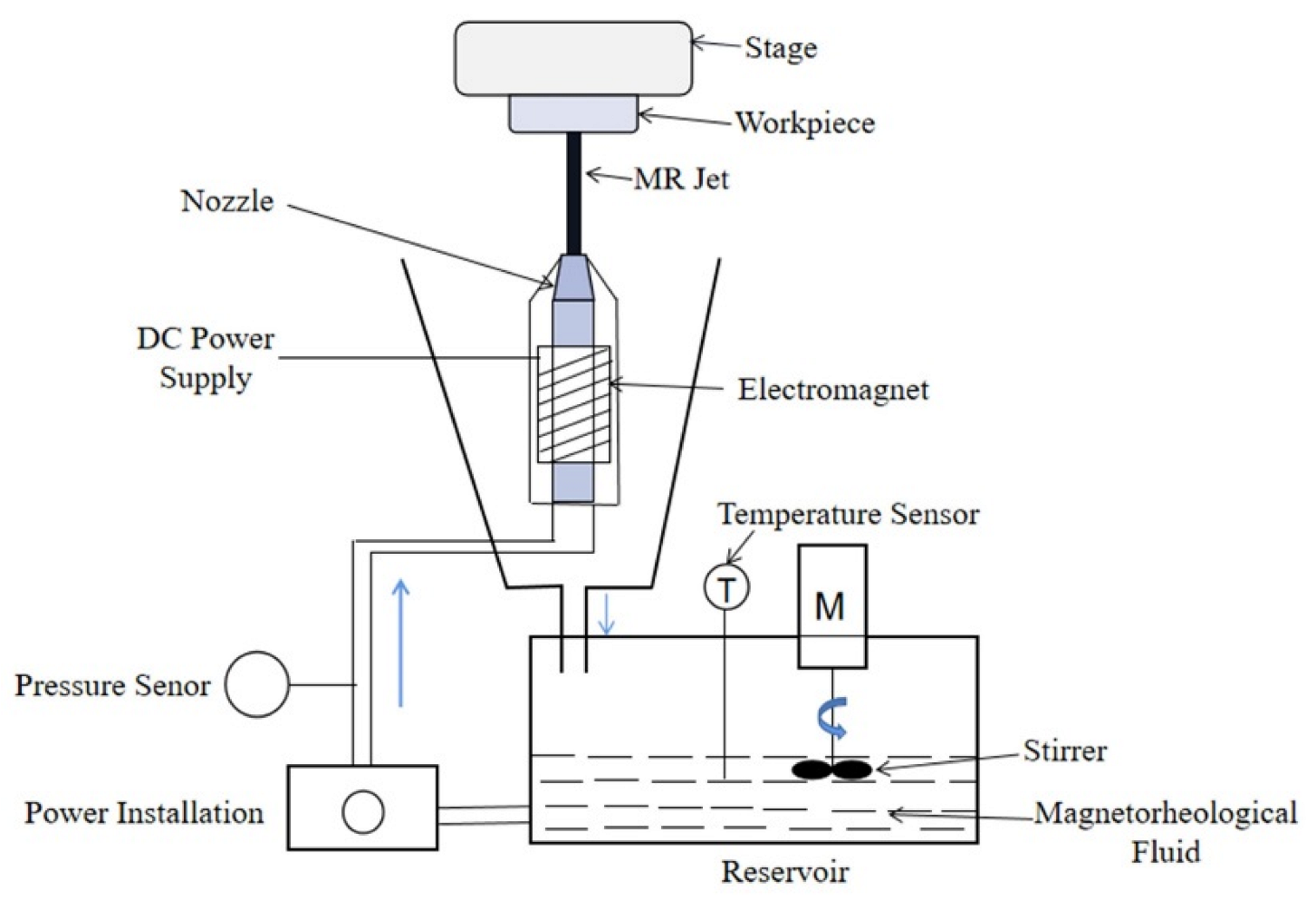
Figure 2. Principle of magnetorheological jet polishing [46].
Lubricants 10 00237 g002
Figure 3. Division of the action zone between the fluid and the workpiece Reprinted with permission from Ref. [49]. Copyright 2015 Springer Nature.
Lubricants 10 00237 g003
Figure 5. Schematic diagram of magnetorheological effect [58]. (a) Magnetic off; (b) Magnetic on.
Lubricants 10 00237 g005
Figure 6. Normalized profiles of the generalized removal rate and surface power density Reprinted with permission from Ref. [65] Copyright 2007 SAGE.
Lubricants 10 00237 g006
Figure 7. Removal function optimization [58].
Lubricants 10 00237 g007
Figure 8. Eccentric motion diagram Reprinted with permission from Ref. [67]. Copyright 2013 Elsevier.
Lubricants 10 00237 g008
Figure 9. Nozzle structure drawing: (a) cylindrical nozzle; (b) conical nozzle; (c) conical column nozzle; (d) conical column diffusion nozzle [78].
Lubricants 10 00237 g009
Figure 10. Three types of nozzles: (a) linear distributed nozzles; (b) surround distributed nozzles; (c) array distributed nozzles Reprinted with permission from Ref. [80]. Copyright 2017 Elsevier.
Lubricants 10 00237 g010
Figure 11. MJP processing device Reprinted with permission from Ref. [65]. Copyright 2006 Elsevier.
Lubricants 10 00237 g011
Figure 12. Experimental setup. (a) CAD of polishing setup; (b) main components of actual hardware Reprinted with permission from Ref. [67]. Copyright 2013 Elsevier.
Lubricants 10 00237 g012
Figure 13. Schematic diagram of micro MR fluid jet polishing system Reprinted with permission from Ref. [89]. Copyright 2016 Smart Materials and Structures.
Lubricants 10 00237 g013
Figure 14. Experimental setup of MR jet erosion Reprinted with permission from Ref. [91]. Copyright 2021 Springer Nature.
Lubricants 10 00237 g014
Figure 15. MJP system with the robot Reprinted with permission from Ref. [53]. Copyright 2020 Applied Optics.
Lubricants 10 00237 g015
Figure 16. The simulation results at an incident angle of 90°. (a) Fluid velocity distribution; (b) the workpiece surface pressure distribution.
Lubricants 10 00237 g016
Figure 17. The simulation results at an incident angle of 60°. (a) Fluid velocity distribution; (b) the workpiece surface pressure distribution.
Lubricants 10 00237 g017
Figure 18. The fluid impact the workpiece at 60°, a distribution curve of positive pressure.
Lubricants 10 00237 g018
Figure 19. The fluid impact the workpiece at 60°, a distribution curve of shear force on the workpiece surface.
Lubricants 10 00237 g019
Table 1. Related parameters of the simulation.
ParameterUnitData
Nozzle outlet diametermm2
The workpiece lengthmm50
Processing distancemm50
Initial fluid velocitym·s−140
The initial pressurePa101,325
Table 2. The effect of MJP processing technique.
AuthorsWork MaterialStudiesData
Zhang et al. [50,63]K9 glassPV, RMSPV: 0.563 to 0.176 μm
RMS:0.137 to 0.034 μm
Dai et al. [58]K9 glassPV0.563 to 0.176 μm
Wang et al. [95]K9 glassPV, RMSPV: 0.162 to 0.024 μm
RMS:0.043 to 0.003 μm
Yang et al. [69]K9 glassRa4.86 nm
Li et al. [96]BK7 glassRMS40 to 6.8 nm
Kim et al. [68]BK7 glassRMS1.3 nm
Kordonski et al. [41]PCAPV, RMSPV: 1740 to 133 nm
RMS:255 to 12.1 μm
Lu et al. [98]SteelRa812 to 88 nm
Lee et al. [64,99]Cu, NiRaCu:1.84 nm
Ni:2.31 nm
Publisher’s Note: MDPI stays neutral with regard to jurisdictional claims in published maps and institutional affiliations.