Magnetic Field Vector Structure of NGC6946

Abstract
1. Introduction
2. Method
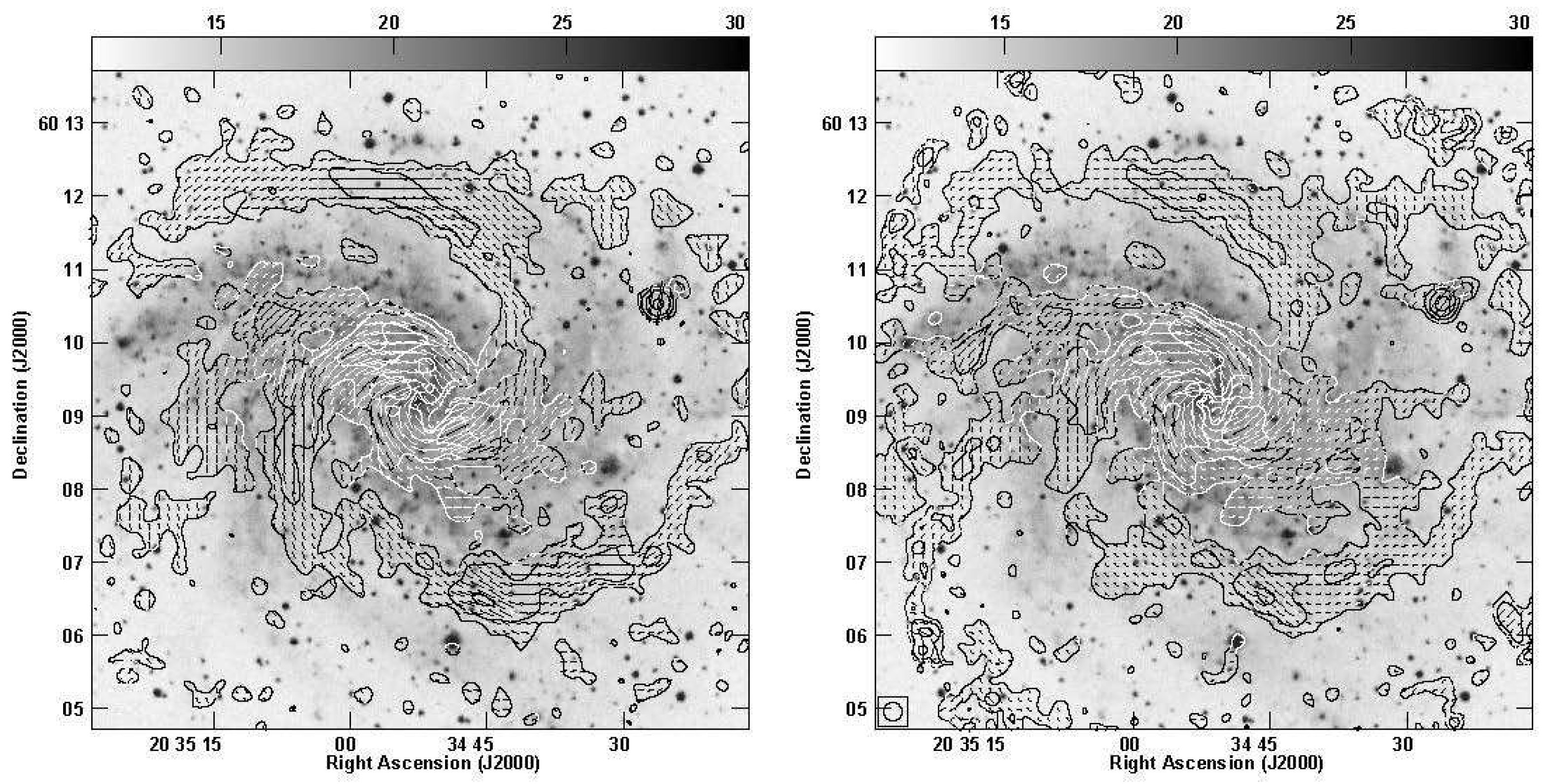
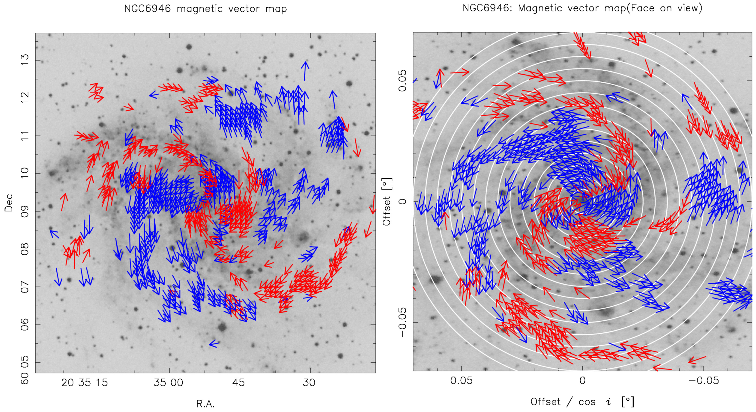
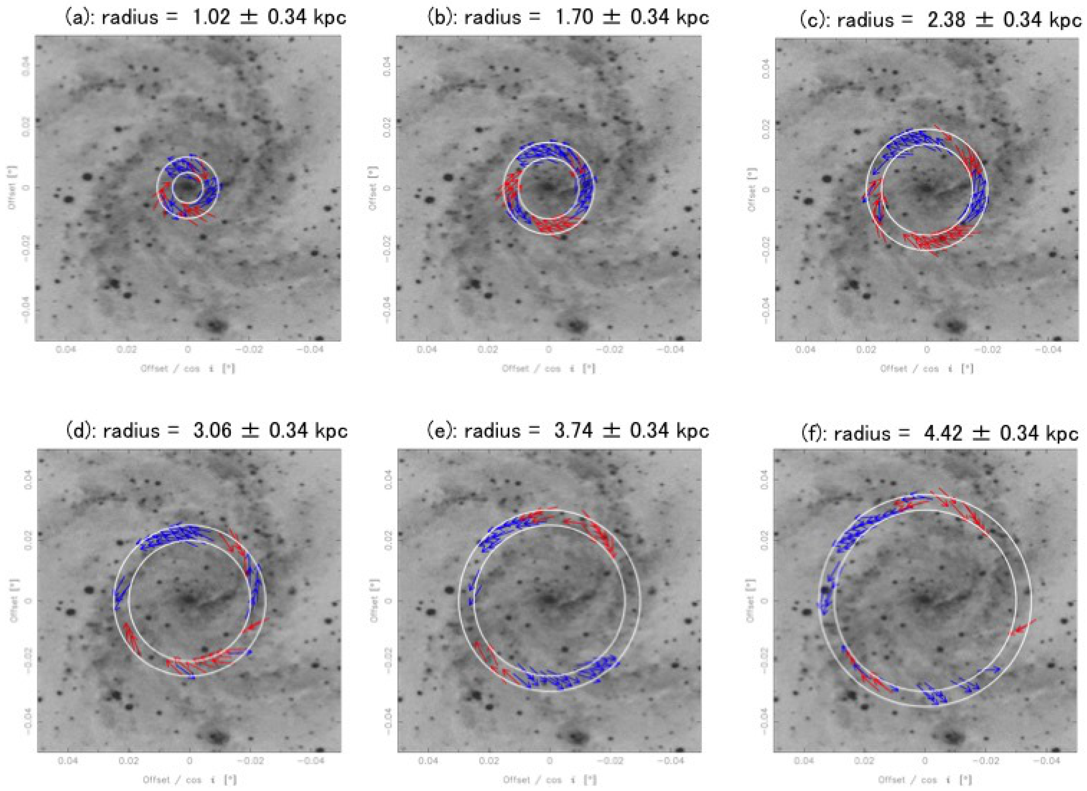
3. Result
4. Discussion
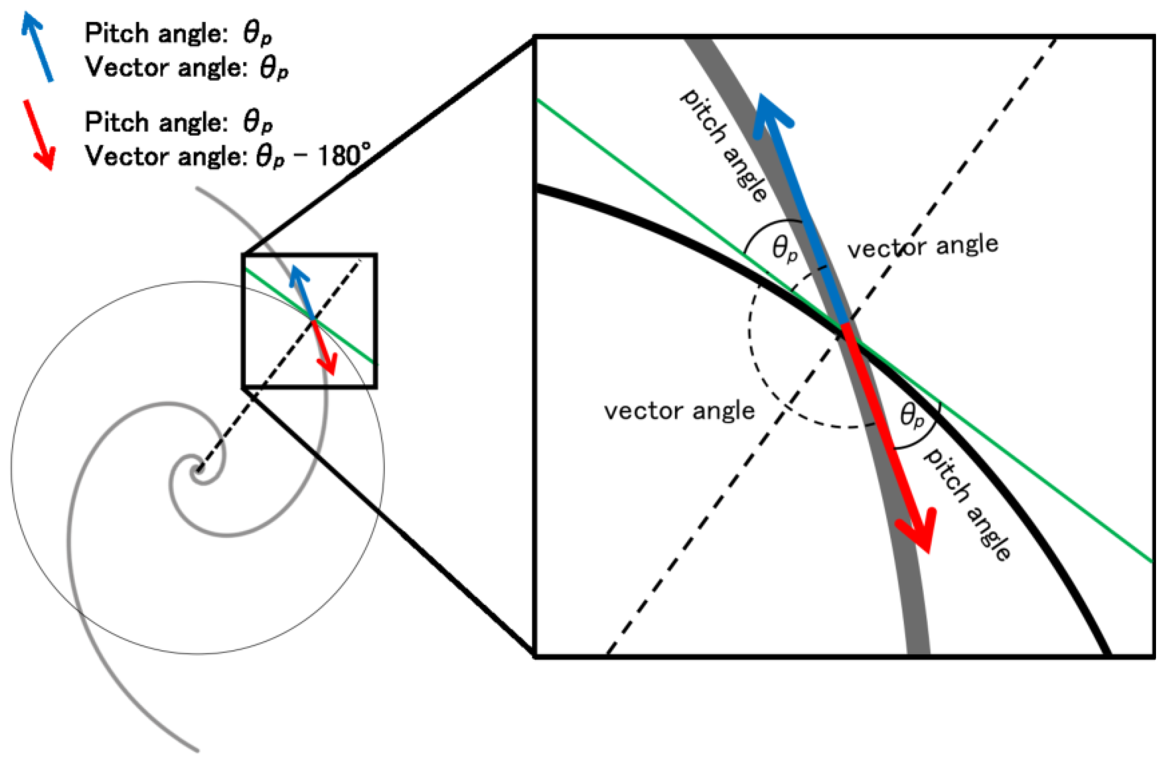
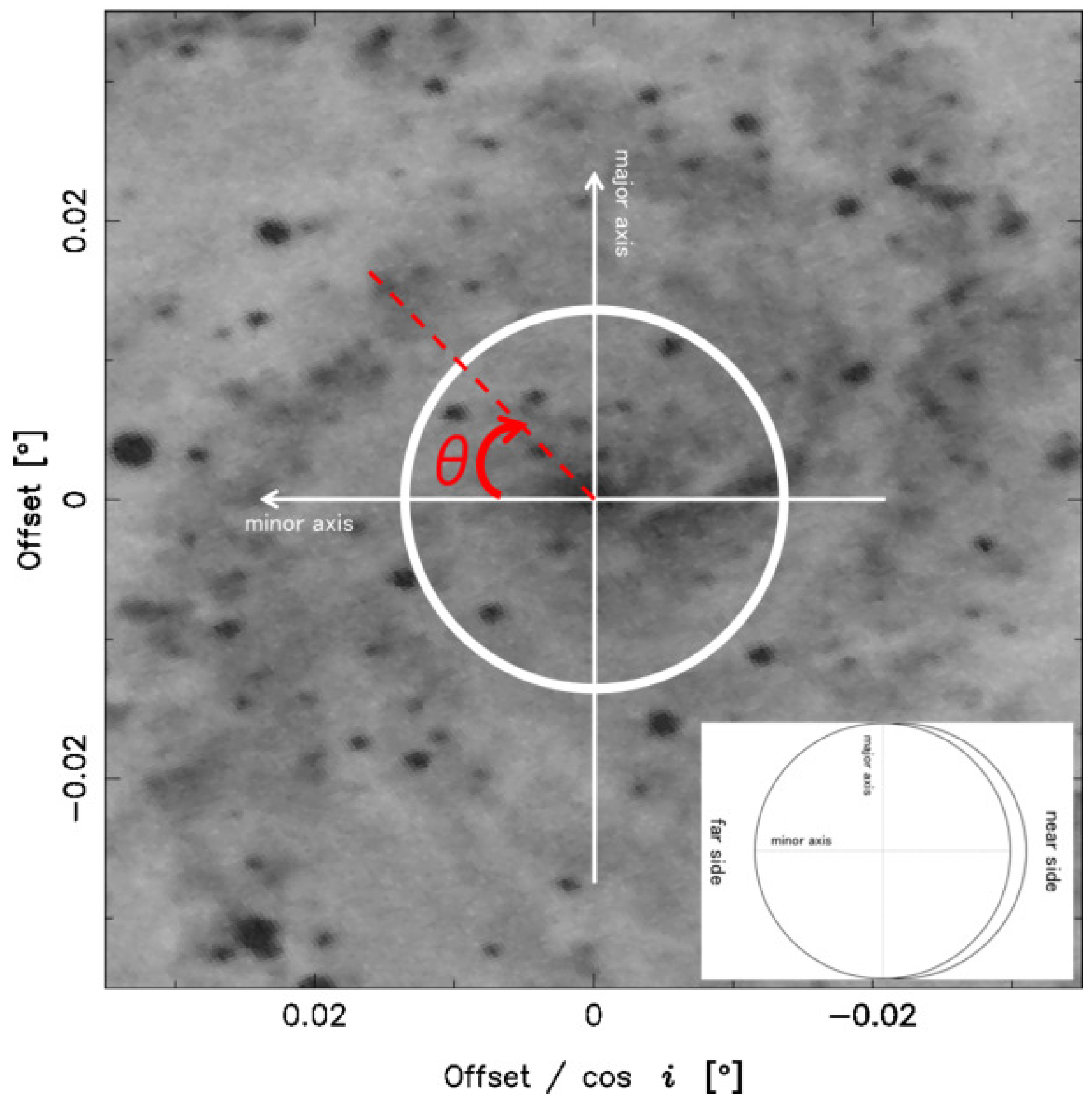
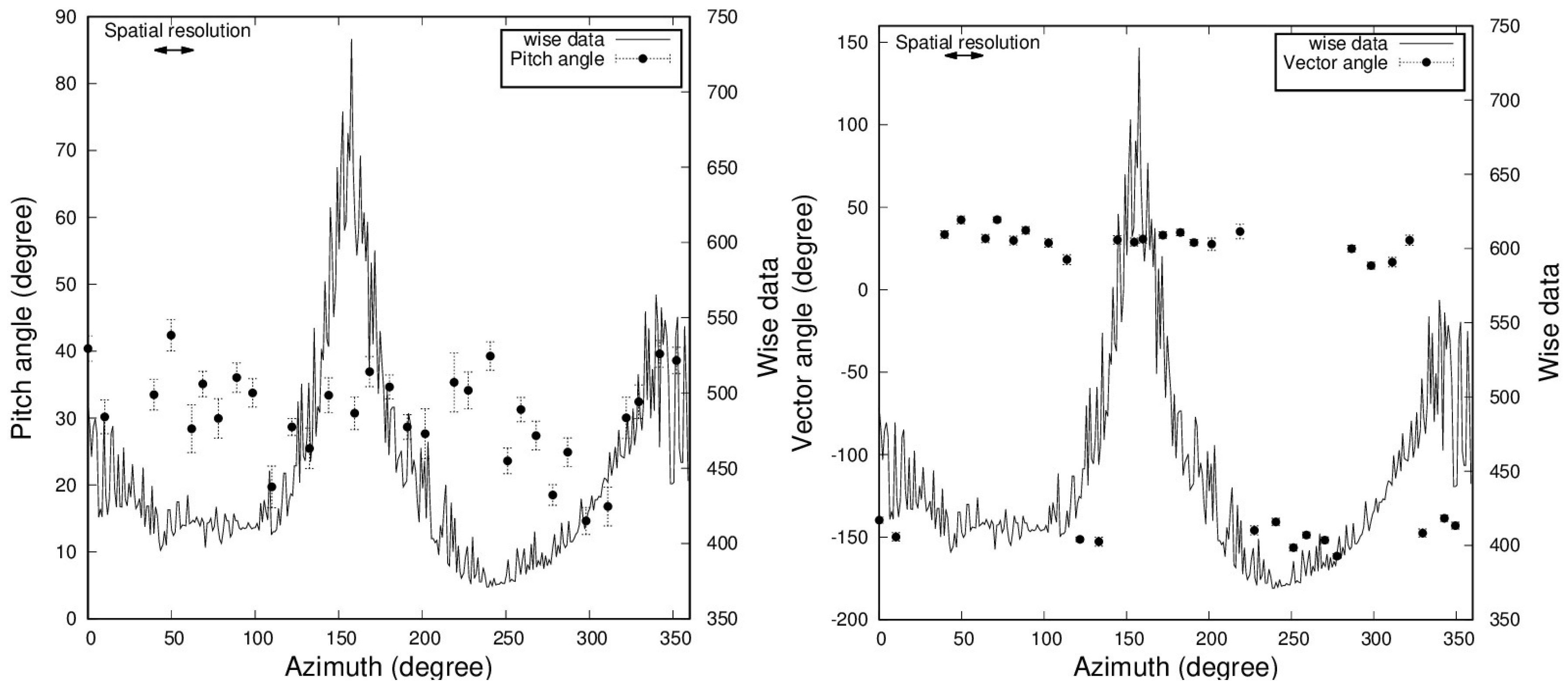
4.1. Azimuthal Change of the Pitch Angle
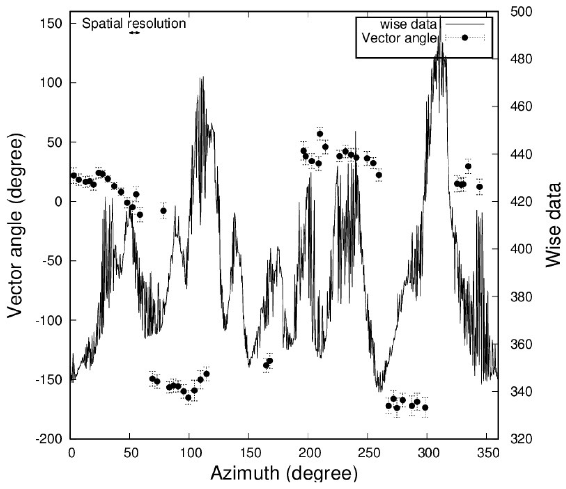
4.2. Azimuthal Change of the Vector Angle
4.3. Magnetic Field Reversals in the Outer Region
5. Summary
Author Contributions
Funding
Acknowledgments
Conflicts of Interest
References
- Sofue, Y.; Fujimoto, M.; Wielebinski, R. Global structure of magnetic fields in spiral galaxies. Ann. Rev. Astron. Astrophys. 1986, 24, 459–497. [Google Scholar] [CrossRef]
- Beck, R. Magnetic fields in spiral galaxies. Astron. Astrophys. Rev. 2016, 24, 4. [Google Scholar] [CrossRef]
- Akahori, T.; Nakanishi, H.; Sofue, Y.; Fujita, Y.; Ichiki, K.; Ideguchi, S.; Kameya, O.; Kudoh, T.; Kudoh, Y.; Machida, M.; et al. Cosmic magnetism in centimeter- and meter-wavelength radio astronomy. Publ. Astron. Soc. Jpn. 2018, 70, R2. [Google Scholar] [CrossRef]
- Han, J.L.; Manchester, R.N.; Lyne, A.G.; Qiao, G.J.; van Straten, W. Pulsar Rotation Measures and the Large-Scale Structure of the Galactic Magnetic Field. Astrophys. J. 2006, 642, 868–881. [Google Scholar] [CrossRef]
- Haverkorn, M. Magnetic Fields in the Milky Way. Magn. Fields Diffus. Media 2015, 407, 483. [Google Scholar]
- Beck, R. Magnetic fields in the nearby spiral galaxy IC 342: A multi-frequency radio polarization study. Astron. Astrophys. 2015, 578, A93. [Google Scholar] [CrossRef]
- Stein, Y.; Dettmar, R.-J.; Irwin, J.; Beck, R.; Weżgowiec, M.; Miskolczi, A.; Krause, M.; Heesen, V.; Wiegert, T.; Heald, G.; et al. CHANG-ES. XIII. Transport processes and the magnetic fields of NGC 4666: Indication of a reversing disk magnetic field. Astron. Astrophys. 2019, 623, A33. [Google Scholar] [CrossRef]
- Harnett, J.I.; Beck, R.; Buczilowski, U.R. The magnetic field of NGC6946. Astron. Astrophys. 1989, 208, 32–38. [Google Scholar]
- Beck, R. Magnetic fields and interstellar gas clouds in the spiral galaxy NGC6946. Astron. Astrophys. 1991, 251, 15–26. [Google Scholar]
- Ehle, M.; Beck, R. Ionized Gas and Intrinsic Magnetic Fields in the Spiral Galaxy NGC6946. Astron. Astrophys. 1993, 273, 45. [Google Scholar]
- Beck, R.; Hoernes, P. Magnetic spiral arms in the galaxy NGC6946. Nature 1996, 379, 47–49. [Google Scholar] [CrossRef]
- Beck, R. Magnetism in the spiral galaxy NGC6946: Magnetic arms, depolarization rings, dynamo modes, and helical fields. Astron. Astrophys. 2007, 470, 539–556. [Google Scholar] [CrossRef]
- Chupin, A.; Beck, R.; Frick, P.; Heald, G.; Sokoloff, D.; Stepanov, R. Magnetic arms of NGC6946 traced in Faraday cubes at low radio frequencies. Astron. Nachrichten 2018, 339, 440–446. [Google Scholar] [CrossRef]
- Kuno, N.; Sato, N.; Nakanishi, H.; Hirota, A.; Tosaki, T.; Shioya, Y.; Sorai, K.; Nakai, N.; Nishiyama, K.; Vila-VilarÓ, B.; et al. Nobeyama CO Atlas of Nearby Spiral Galaxies: Distribution of Molecular Gas in Barred and Nonbarred Spiral Galaxies. Publ. Astron. Soc. Jpn. 2007, 59, 117–166. [Google Scholar] [CrossRef]
- de Vaucouleurs, G.; de Vaucouleurs, A.; Corwin, H.G., Jr.; Buta, R.J.; Paturel, G.; Fouque, P. VizieR Online Data Catalog: Third Reference Catalogue of Bright Galaxies (RC3); VizieR On-line Data Catalog: VII/137B; Springer: New York, NY, USA, 1992; Volume 7137. [Google Scholar]
- Anand, G.S.; Rizzi, L.; Tully, R.B. A Robust Tip of the Red Giant Branch Distance to the Fireworks Galaxy (NGC 6946). Astron. J. 2018, 156, 105. [Google Scholar] [CrossRef]
- Berkhuijsen, E.M.; Horellou, C.; Krause, M.; Neininger, N.; Poezd, A.D.; Shukurov, A.; Sokoloff, D.D. Magnetic fields in the disk and halo of M 51. Astron. Astrophys. 1997, 318, 700–720. [Google Scholar]
- Fletcher, A.; Beck, R.; Shukurov, A.; Berkhuijsen, E.M.; Horellou, C. Magnetic fields and spiral arms in the galaxy M51. Mon. Not. R. Astron. Soc. 2011, 412, 2396–2416. [Google Scholar] [CrossRef]
- Nakanishi, H.; Kurahara, K.; Anraku, K. Magnetic-Field Vector Maps of Nearby Spiral Galaxies. Galaxies 2019, 7, 32. [Google Scholar] [CrossRef]
- Han, J.L. Observing Interstellar and Intergalactic Magnetic Fields. Annu. Rev. Astron. Astrophys. 2017, 55, 111–157. [Google Scholar] [CrossRef]
- Wright, E.L.; Eisenhardt, P.R.M.; Mainzer, A.K.; Ressler, M.E.; Cutri, R.M.; Jarrett, T.; Kirkpatrick, J.D.; Padgett, D.; McMillan, R.S.; Skrutskie, M.; et al. The Wide-field Infrared Survey Explorer (WISE): Mission Description and Initial On-orbit Performance. Astron. J. 2010, 140, 1868–1881. [Google Scholar] [CrossRef]
- Walter, F.; Brinks, E.; de Blok, W.J.G.; Bigiel, F.; Kennicutt, R.C., Jr.; Thornley, M.D.; Leroy, A. THINGS: The H I Nearby Galaxy Survey. Astron. J. 2008, 136, 2563–2647. [Google Scholar] [CrossRef]
- McLean, B.J.; Greene, G.R.; Lattanzi, M.G.; Pirenne, B. The Status of the Second Generation Digitized Sky Survey and Guide Star Catalog. Astron. Data Anal. Softw. Syst. IX 2000, 216, 145. [Google Scholar]
- Rohde, R.; Beck, R.; Elstner, D. Magnetic arms in NGC 6946 generated by a turbulent dynamo. Astron. Astrophys. 1999, 350, 423–433. [Google Scholar]


| RA (J2000) | [14] | |
| Dec (J2000) | [14] | |
| Morphology | SAB | [15] |
| Distances | 7.72 Mpc | [16] |
| Position Angle | [14] | |
| Inclination | [14] |
| Observation Band | C | X |
|---|---|---|
| Stokes I rms | 67 | 63 |
| Stokes Q rms | 17 | 12 |
| Stokes U rms | 22 | 14 |
| Beam size |
© 2019 by the authors. Licensee MDPI, Basel, Switzerland. This article is an open access article distributed under the terms and conditions of the Creative Commons Attribution (CC BY) license (http://creativecommons.org/licenses/by/4.0/).
Share and Cite
Kurahara, K.; Nakanishi, H. Magnetic Field Vector Structure of NGC6946. Galaxies 2019, 7, 59. https://doi.org/10.3390/galaxies7020059
Kurahara K, Nakanishi H. Magnetic Field Vector Structure of NGC6946. Galaxies. 2019; 7(2):59. https://doi.org/10.3390/galaxies7020059
Chicago/Turabian StyleKurahara, Kohei, and Hiroyuki Nakanishi. 2019. "Magnetic Field Vector Structure of NGC6946" Galaxies 7, no. 2: 59. https://doi.org/10.3390/galaxies7020059
APA StyleKurahara, K., & Nakanishi, H. (2019). Magnetic Field Vector Structure of NGC6946. Galaxies, 7(2), 59. https://doi.org/10.3390/galaxies7020059