
Simulation of the Circulating Motion of the Working Medium and Metal Removal during Multi-Energy Processing under the Action of Vibration and Centrifugal Forces


 ,
,  and
and 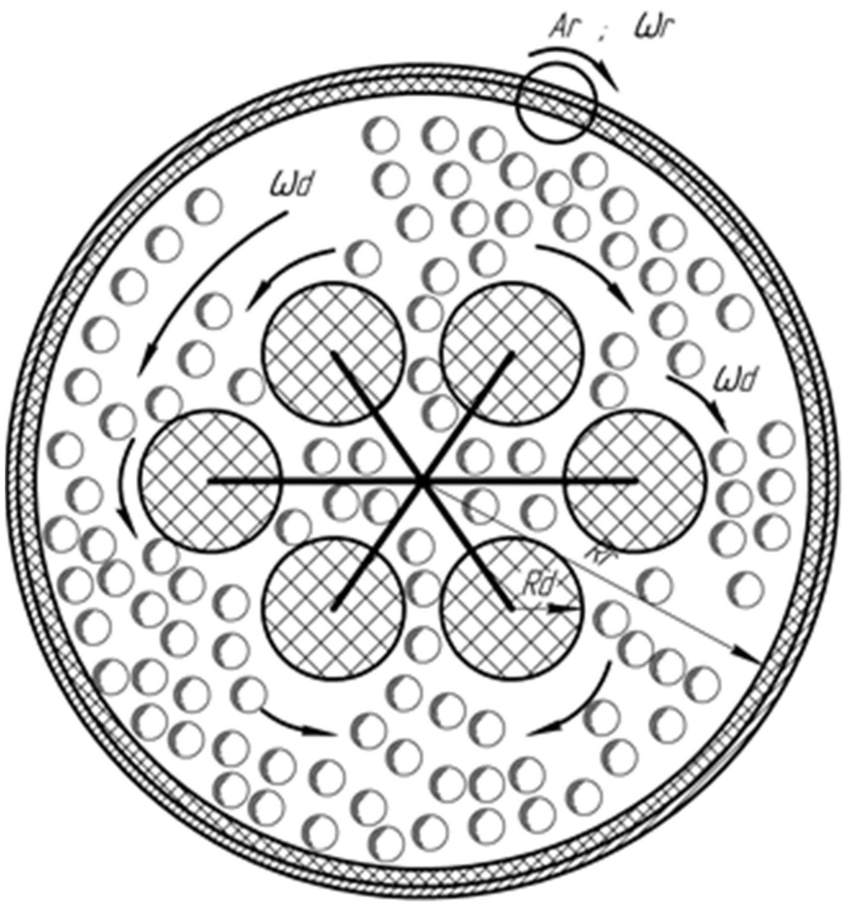
Abstract
1. Introduction
2. General Approach
3. The Circulating Movement of the Abrasive Medium Granules under the Action of a Rotating Impeller
3.1. Equations of the Circulating Movement
- the equation for determining the circulation motion, neglecting changes in the motion parameters along the vertical axis, that is, the flow will be considered as flat;
- the gravitation is neglected;
- the flow will be considered as laminar;the action of the impeller on the abrasive medium granules is replaced by the distributed force acting per unit volume at any point of the pseudo-gas.
3.2. Determination of Unknown Constants in the Expression of the Velocity of the Abrasive Medium Granules Moving under the Action of the Rotating Impeller
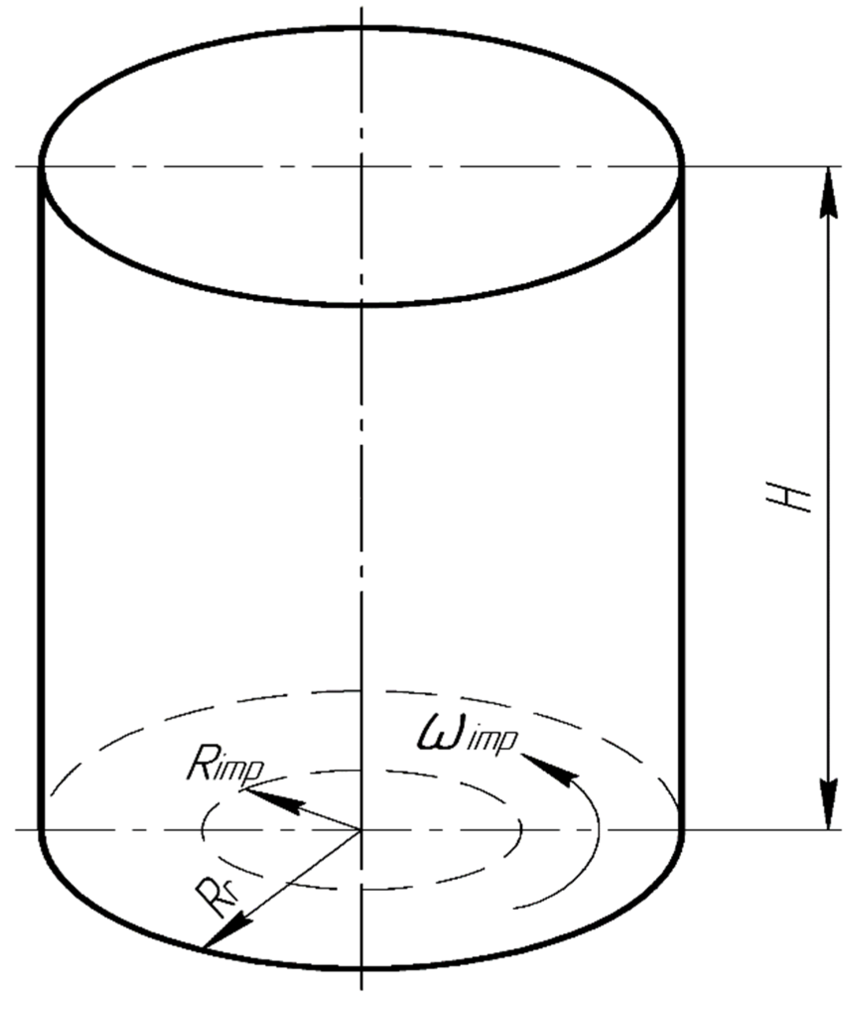
4. The Total Action on the Surface of the Processed Part
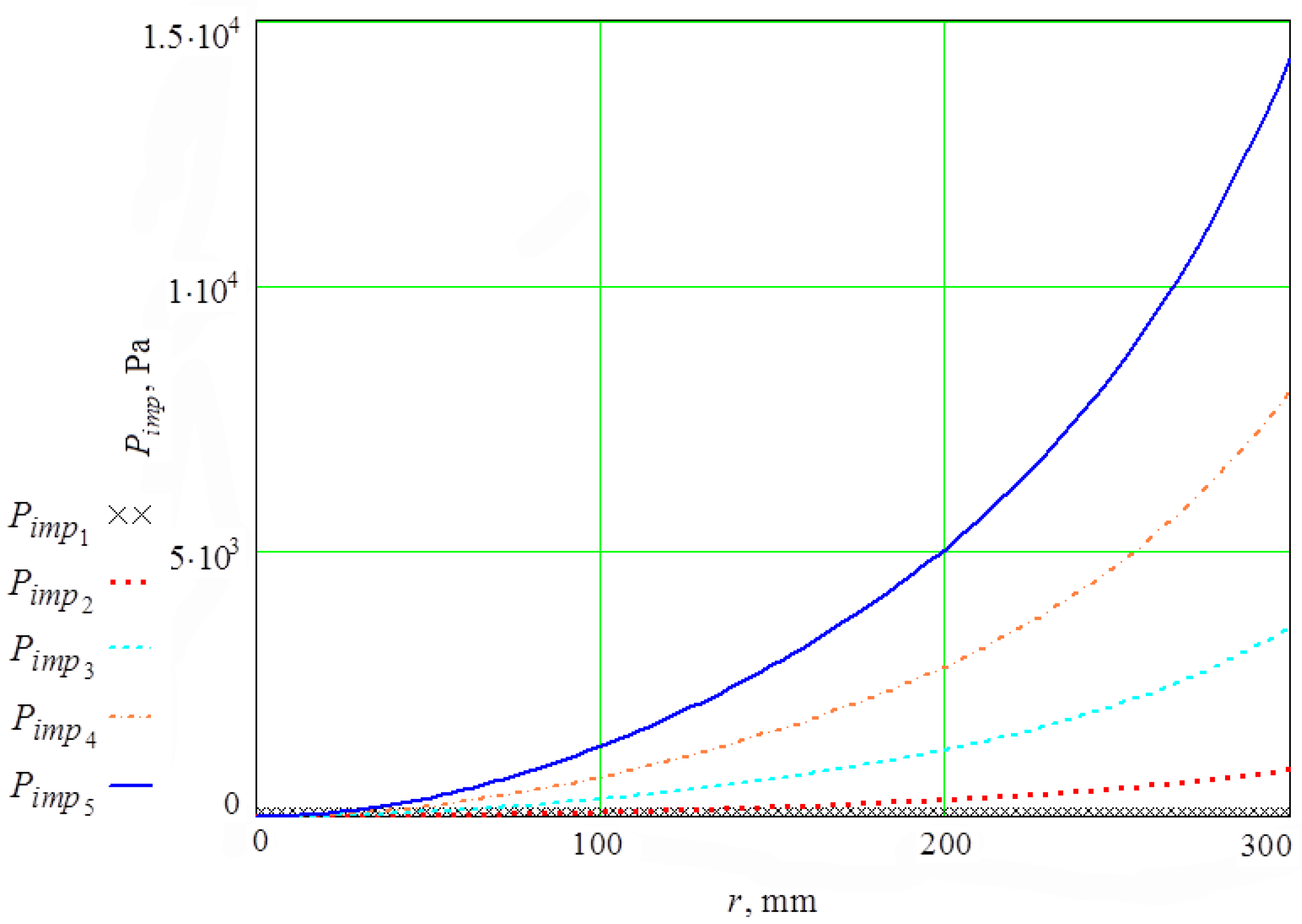
4.1. Pressure Created by the Oscillating Walls of the Vibration Machine
4.2. Total Pressure on the Surface of the Processed Part and the Average Velocity of the Abrasive Granules Colliding with It
5. Removal of Metal Using Multi-Energy Technology
6. Conclusions
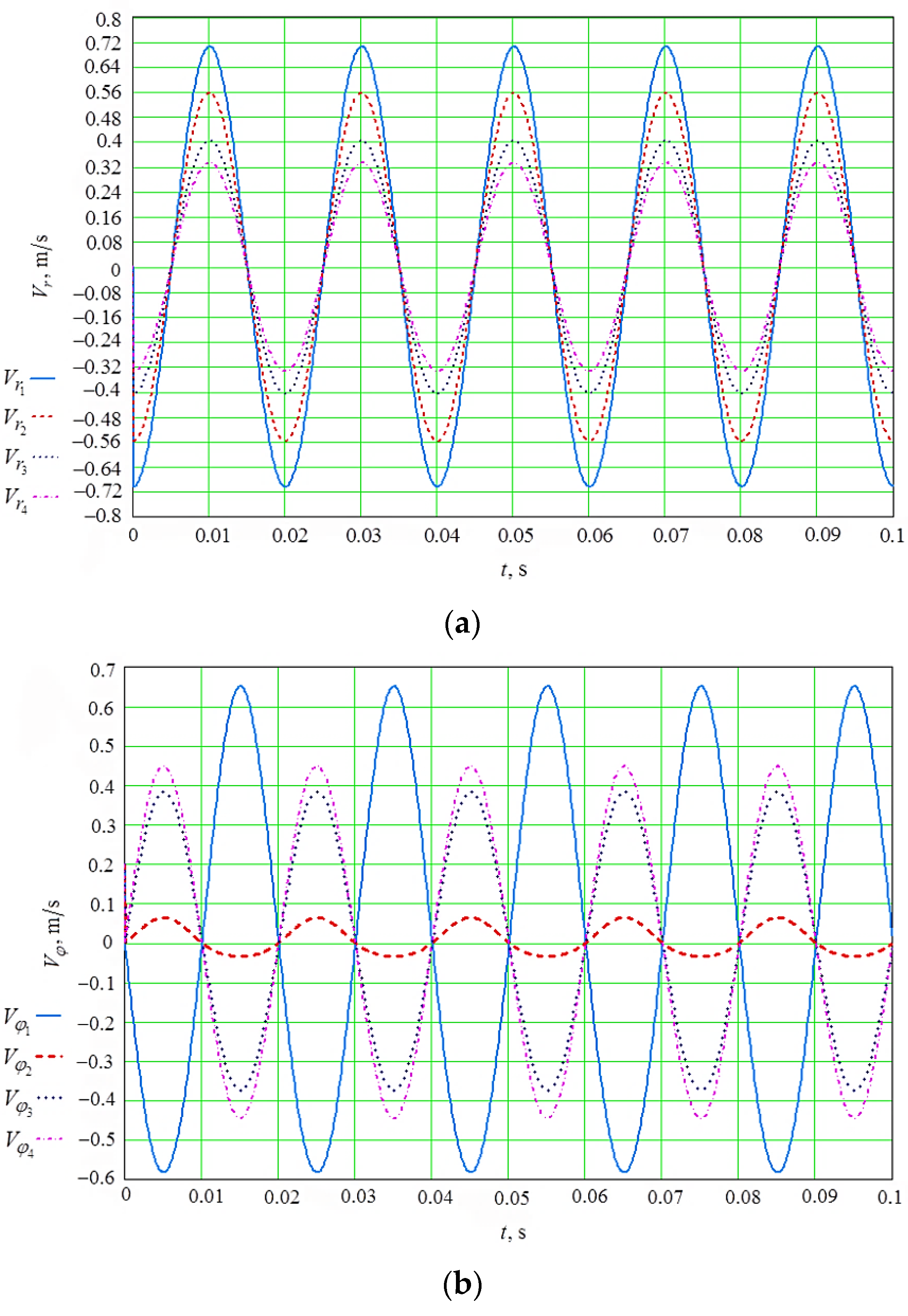
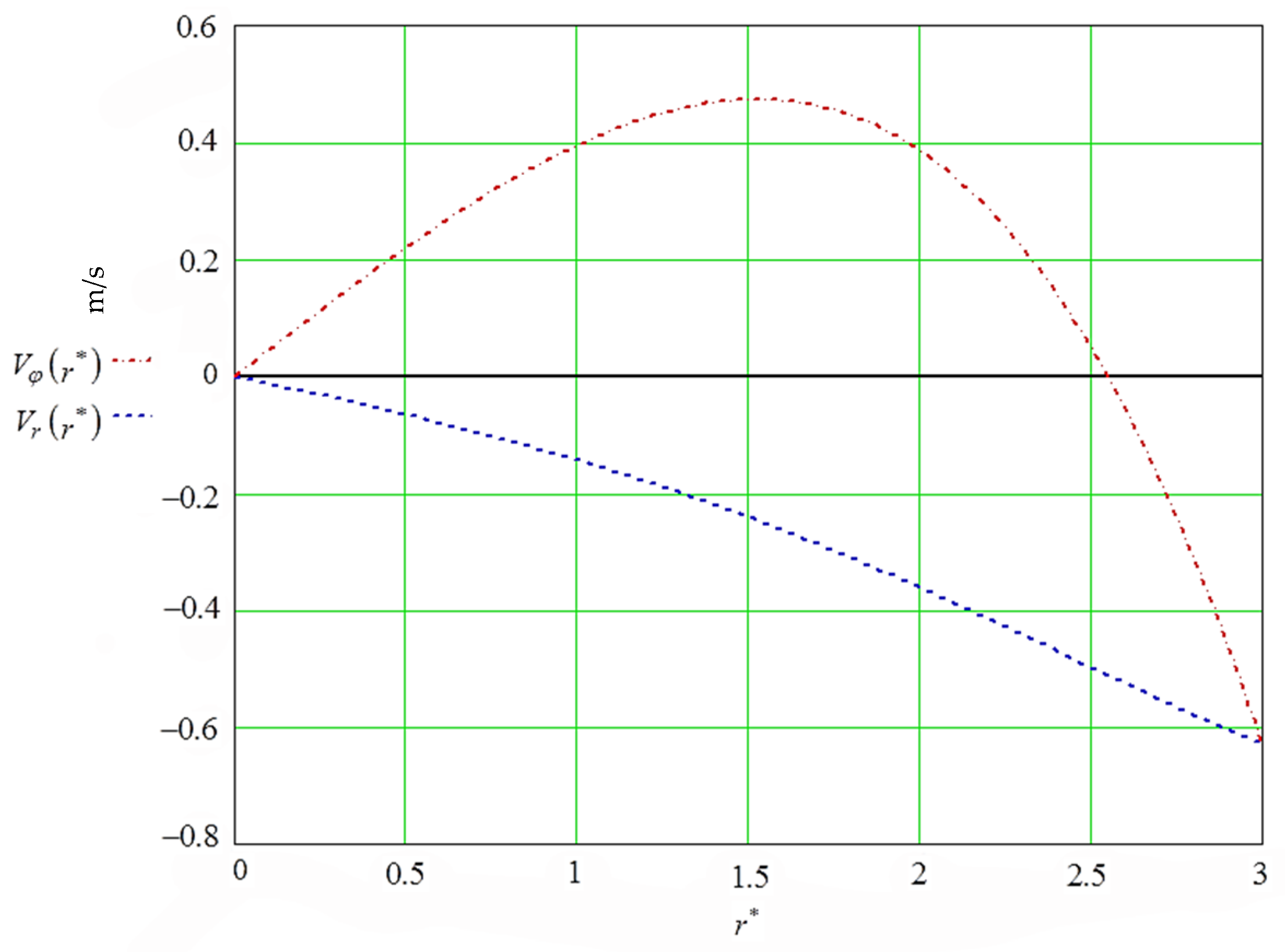
- It has been established that the circular motion of all points of the reservoir surface of the vibrating machine can be decomposed into radial and tangential components, which create wave motion in the granules of the working medium, without leading to the appearance of stationary radial and tangential flows. The dependencies of the radial and tangential components of the velocity of movement of the granules of the medium inside the oscillating cylindrical reservoir on its radius and period of oscillations are obtained.
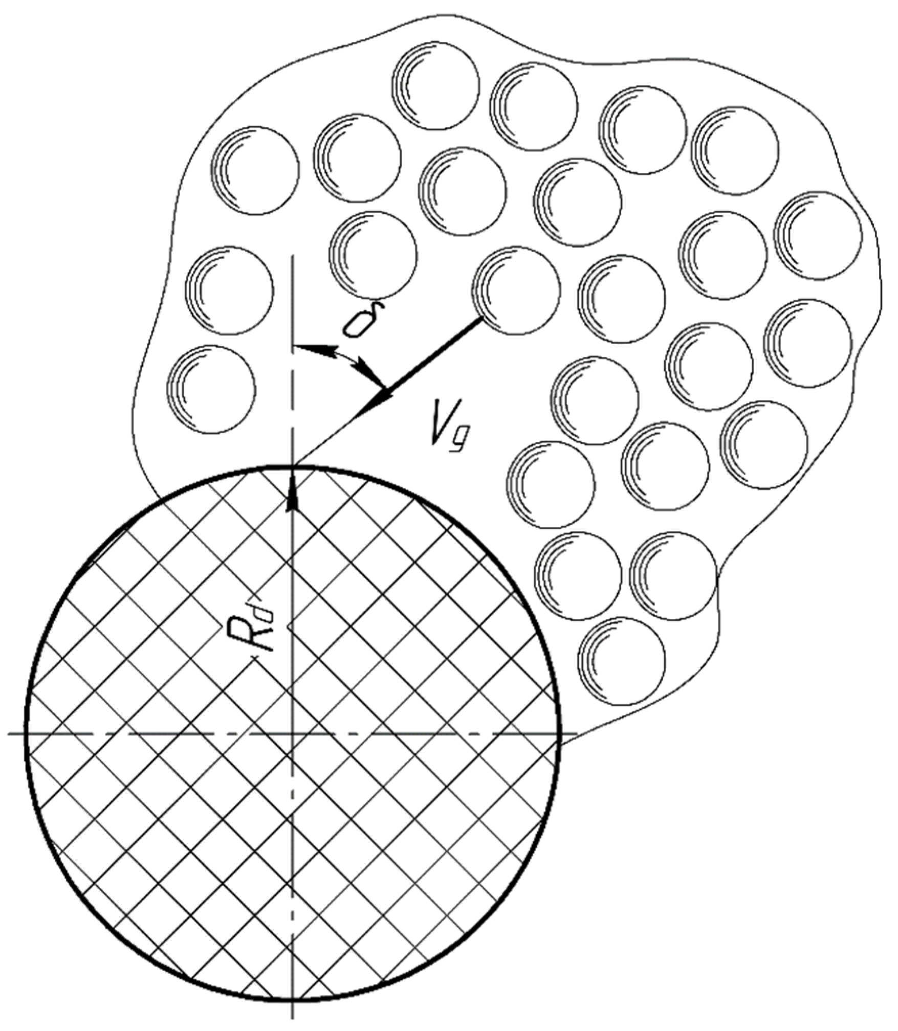
- It has been found that when distributing the pressure of the working medium granules over the surface of the rotating processed part, it is necessary to take into account the force of the impeller and the pressure caused by the rotation of the processed part, as well as the friction force between the surface of the rotating processed part and the granules of the medium.
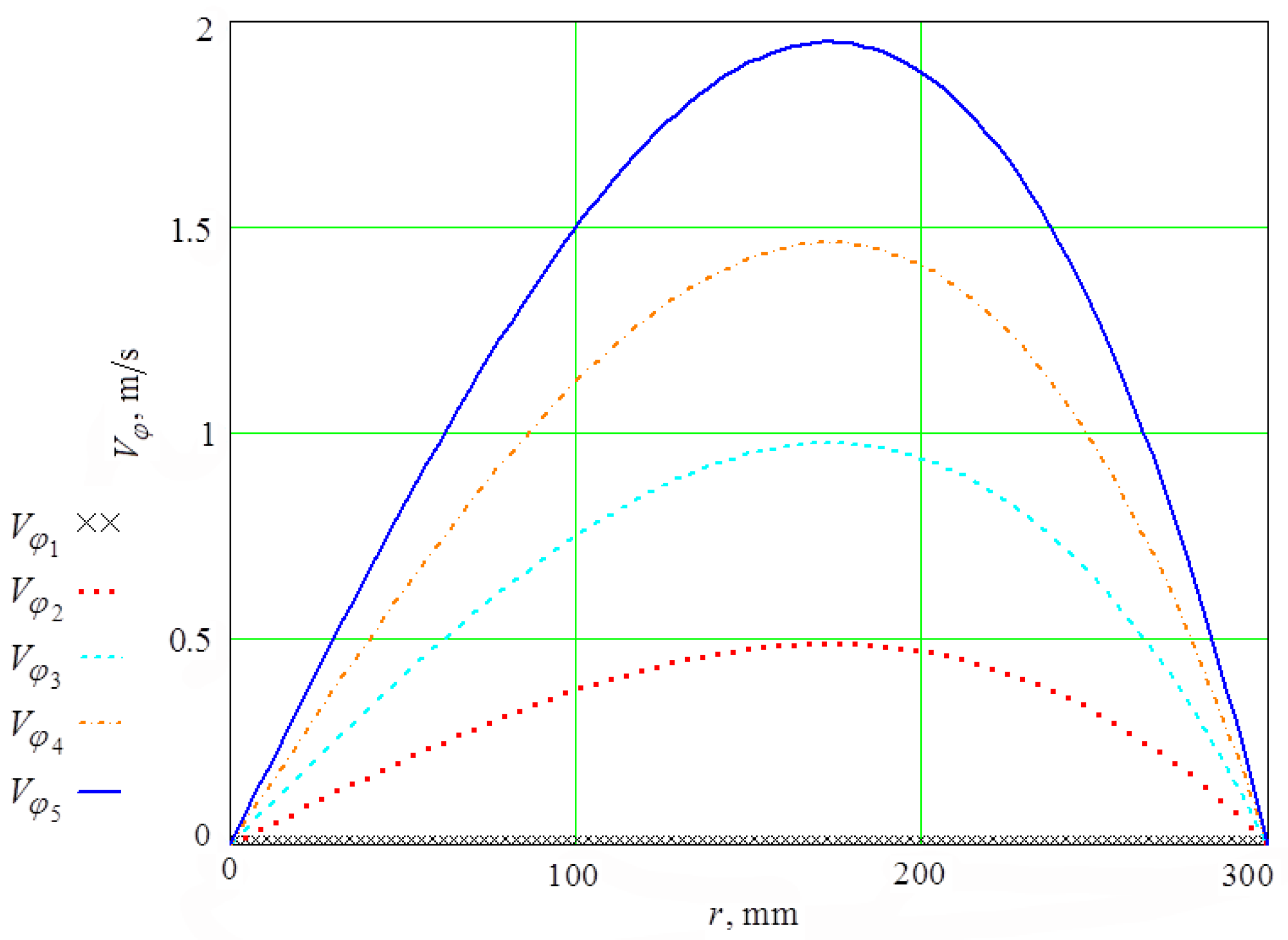
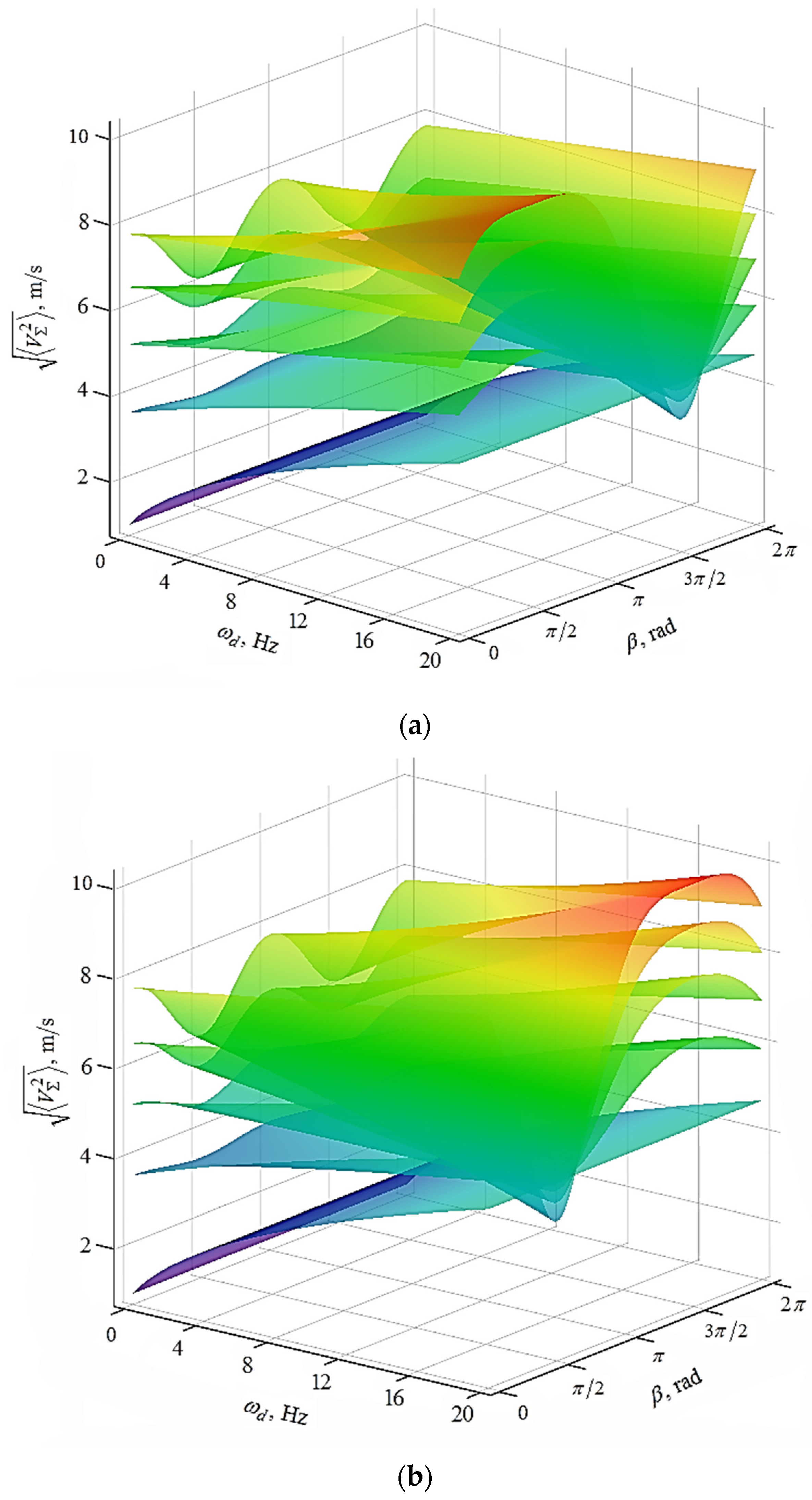
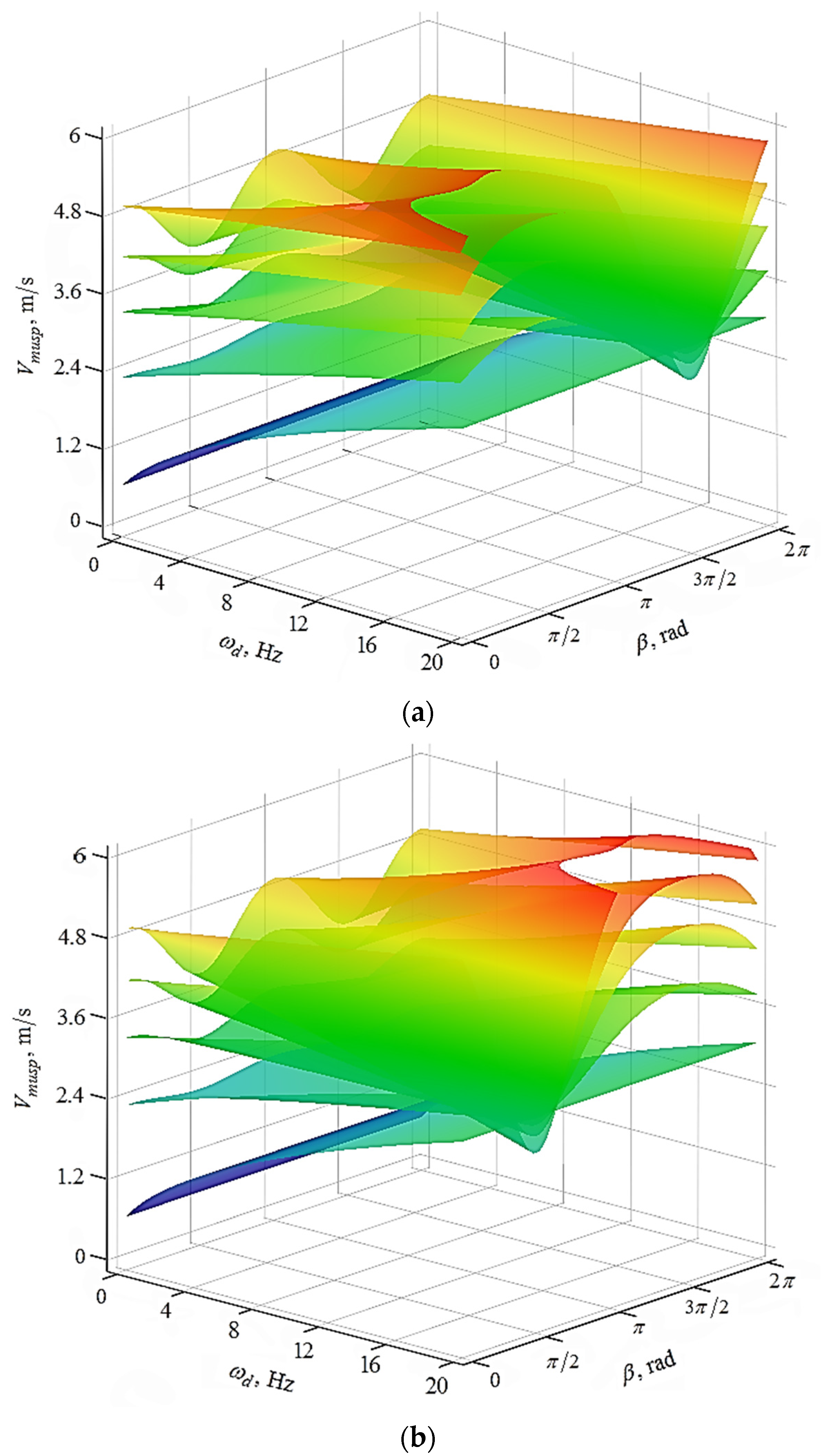
- Graphical dependencies of the speed of approach of any point of the surface of the part and the granule of the medium flying up to it on the angle of the ordinate axis and the angular velocity of rotation of the part for different values of the angular velocity of the impeller are obtained.
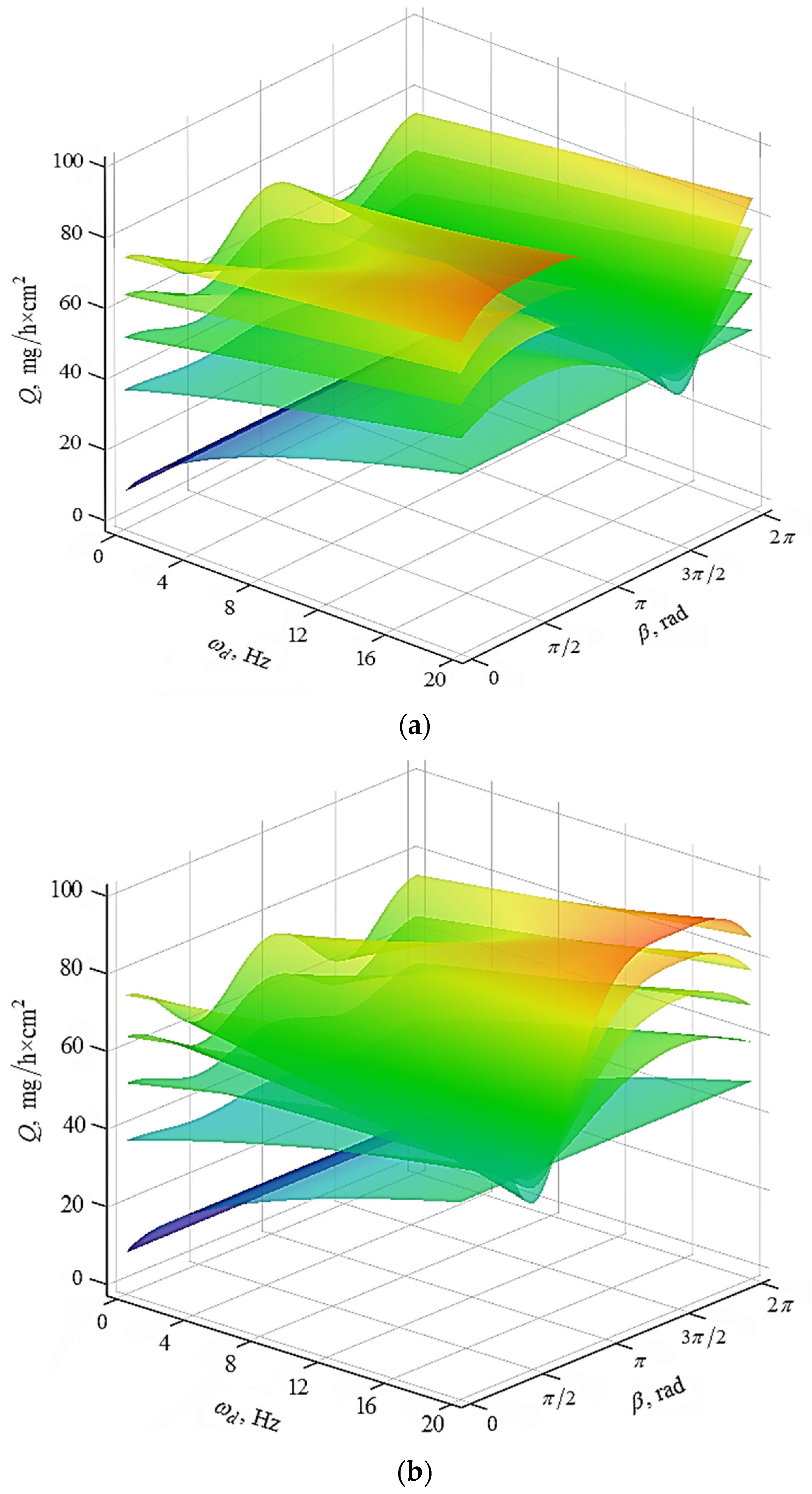
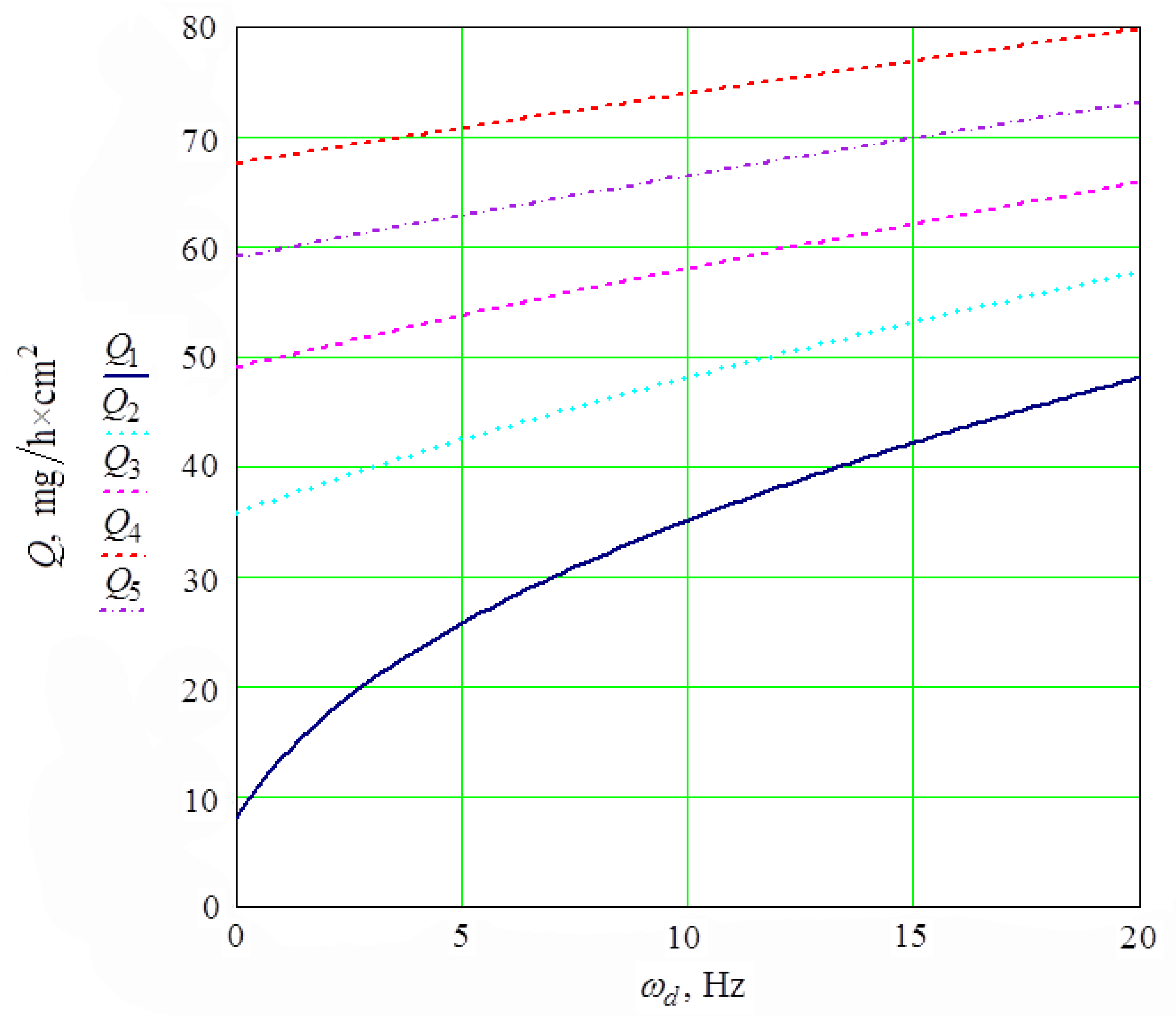
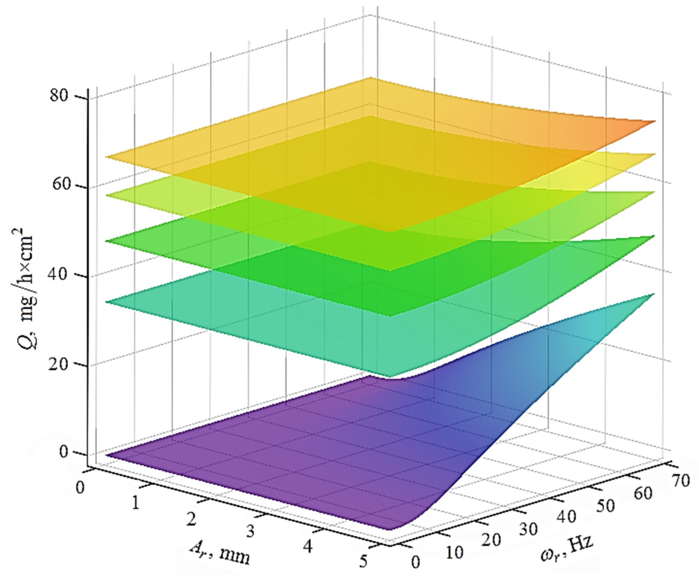
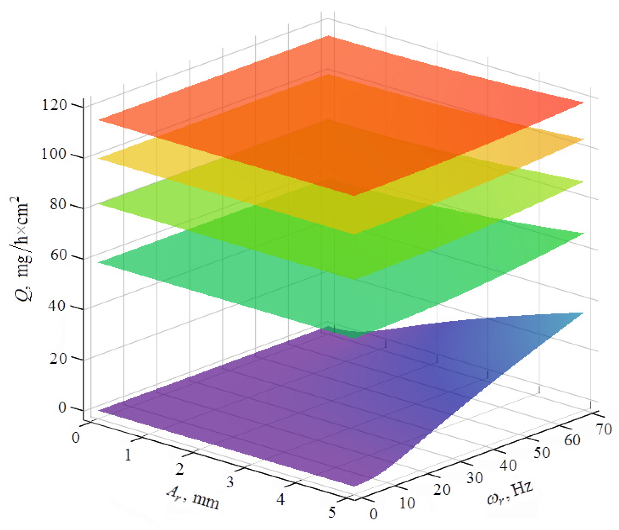
- It has been established that the integral metal removal increases with an increase in the rotation speeds of the processed part and the impeller. The presence of removal at these speeds equal to zero is explained by the action of the oscillating reservoir wall. The share of these influences in the resulting metal removal decreases as the speed of rotation of the impeller and part increases. When the rotation speeds reach for the impeller 12.56 rad/s and for the part 31.4 rad/s, respectively, this fraction is equal to zero.
Author Contributions
Funding
Institutional Review Board Statement
Informed Consent Statement
Data Availability Statement
Conflicts of Interest
References
- Yang, Z.; Zhu, L.; Zhang, G.; Ni, C.; Lin, B. Review of ultrasonic vibration-assisted machining in advanced materials. Int. J. Mach. Tools Manuf. 2020, 156, 103594. [Google Scholar] [CrossRef]
- Malkorra, I.; Souli, H.; Salvatore, F.; Arrazola, P.; Rech, J.; Cici, M.; Mathis, A.; Rolet, J. Modeling of drag finishing—Influence of abrasive media shape. J. Manuf. Mater. Process. 2021, 5, 41. [Google Scholar] [CrossRef]
- Stańczyk, M.; Figlus, T. The effect of selected parameters of vibro-abrasive processing on the surface quality of products made of 6082 aluminium alloy. Materials 2019, 12, 4117. [Google Scholar] [CrossRef]
- Alcaraz, J.Y., II; Ahluwalia, K.; Yeo, S.-H. Predictive models of double-vibropolishing in bowl system using artificial intelligence methods. J. Manuf. Mater. Process. 2019, 3, 27. [Google Scholar] [CrossRef]
- Kundrák, J.; Mitsyk, A.V.; Fedorovich, V.A.; Markopoulos, A.P.; Grabchenko, A.I. Modeling the energy action of vibration and centrifugal forces on the working medium and parts in a vibration machine oscillating reservoir with an impeller. Manuf. Technol. 2021, 21. [Google Scholar] [CrossRef]
- Xie, H.; Zou, Y. Investigation on finishing characteristics of magnetic abrasive finishing process using an alternating magnetic field. Machines 2020, 8, 75. [Google Scholar] [CrossRef]
- Królczyk, J.B. An attempt to predict quality changes in a ten-component granular system. Teh. Vjesnik-Tech. Gaz. 2014, 21, 255–261. [Google Scholar]
- Królczyk, J.B. Metrological changes in the surface morphology of cereal grains in the mixing process. Int. Agrophys. 2016, 30, 193–202. [Google Scholar] [CrossRef]
- Shengqiang, Y.; Wenhui, L. Surface Finishing Theory and New Technology; Springer: Berlin/Heidelberg, Germany, 2018; p. 497. [Google Scholar]
- Gillespie, L. Mass Finishing Handbook; SME Industrial Press Inc.: New York, NY, USA, 2007; p. 800. [Google Scholar]
- Davidson, D.A. Vibratory finishing: Versatile effective. and reliable. Metal Finish. 2008, 106, 30–34. [Google Scholar] [CrossRef]
- Holzknecht, E. Everything you need to know about mechanical / mass finishing. Metal Finish. 2009, 107, 27–31. [Google Scholar] [CrossRef]
- Pandiyan, V.; Castagne, S.; Subbiah, S. High frequency and amplitude effects in vibratory media finishing. Procedia Manuf. 2016, 5, 546–557. [Google Scholar] [CrossRef][Green Version]
- Domblesky, J.; Cariapa, V.; Evans, R. Investigation of vibratory bowl finishing. Int. J. Prod. Res. 2003, 41, 3943–3953. [Google Scholar] [CrossRef]
- Hashimoto, F.; Johnson, S.P. Modeling of vibratory finishing machines. CIRP Ann. 2015, 64, 345–348. [Google Scholar] [CrossRef]
- Hashimoto, F.; Johnson, S.P.; Chaudhari, R.G. Modeling of material removal mechanism in vibratory finishing process. CIRP Ann. 2016, 65, 325–328. [Google Scholar] [CrossRef]
- Królczyk, G.; Gajek, M.; Legutko, S. Predicting the tool life in the dry machining of duplex stainless steel. Eksploat. Niezawodn. 2013, 15, 62–65. [Google Scholar]
- Achiamah-Ampomah, N.; Cheng, K. Investigation on multi-physics simulation-based virtual machining system for vibratory finishing of integrally bladed rotors (IBRS). J. Multiscale Model. 2016, 7, 1640003. [Google Scholar] [CrossRef]
- Mullany, B.; Shahinian, H.; Navare, J.; Azimi, F.; Fleischhauer, E.; Tkacik, P.; Keanini, R. The application of computational fluid dynamics to vibratory finishing processes. CIRP Ann. 2017, 66, 309–312. [Google Scholar] [CrossRef]
- Kundrák, J.; Morgan, M.; Mitsyk, A.V.; Fedorovich, V.A. The effect of the shock wave of the oscillating working medium in a vibrating machine’s reservoir during a multi-energy finishing-grinding vibration processing. Int. J. Adv. Manuf. Technol. 2020, 106, 4339–4353. [Google Scholar] [CrossRef]
- Mamalis, A.; Kundrák, J.; Mitsyk, A.V.; Fedorovich, V.A. Development of modular machine design and technologies of dynamic action for finishing-grinding treatment by an oscillating abrasive medium. Mach. Form. Technol 2015, 7, 1–10. [Google Scholar]
- Mamalis, A.G.; Grabchenko, A.I.; Mitsyk, A.V.; Fedorovich, V.A.; Kundrák, J. Mathematical simulation of motion of working medium at finishing–grinding treatment in the oscillating reservoir. Int. J. Adv. Manuf. Technol. 2014, 70, 263–276. [Google Scholar] [CrossRef]
- Fedorovich, V.A.; Mitsyk, A.V. Mathematical simulation of kinematics of vibrating boiling granular medium at treatment in the oscillating reservoir. Key Eng. Mater. 2013, 581, 456–461. [Google Scholar] [CrossRef]
- Lyu, Y.; Jamil, M.; Ma, P.; He, N.; Gupta, M.K.; Khan, A.M.; Pimenov, D.Y. An ultrasonic-based detection of air-leakage for the unclosed components of aircraft. Aerospace 2021, 8, 55. [Google Scholar] [CrossRef]
- Watson, G.N. A Treatise on the Theory of Bessel Functions; Cambridge University Press: Cambridge, UK, 1995. [Google Scholar]
- Cherny, G.G. Gas Dynamics; Nauka: Moscow, Russia, 1988. (In Russian) [Google Scholar]
- Bird, G.A. Molecular Gas Dynamics and the Direct Simulation of Gas Flows; Oxford Engineering Science Series; Clarendon Press: Oxford, UK, 1994; p. 458. [Google Scholar]
- Batchelor, G.K. An Introduction to Fluid Dynamics; Cambridge University Press: Cambridge, UK, 2000; p. 631. [Google Scholar]
- Sokolov, V. Diffusion of circular source in the channels of ventilation systems. In Advances in Engineering Research and Application. ICERA 2018. Lecture Notes in Networks and Systems; Springer: Cham, Switzerland, 2018; Volume 63, pp. 278–283. [Google Scholar] [CrossRef]
- Sokolov, V. Transfer functions for shearing stress in nonstationary fluid friction. In Proceedings of the 5th International Conference on Industrial Engineering (ICIE 2019). ICIE 2019. Lecture Notes in Mechanical Engineering; Springer: Cham, Switzerland, 2019; pp. 707–715. [Google Scholar] [CrossRef]
- Sivukhin, D.V. General Course of Physics: Vol. 2. Thermodynamics and Molecular Physics; Fizmatlit: Moscow, Russia, 2019; p. 544. (In Russian) [Google Scholar]
- Prandtl, L.; Oswatitsch, K.; Wieghardt, K. Führer Durch Die Strömungslehre; Springer: Berlin/Heidelberg, Germany, 1990. (In German) [Google Scholar]
- Kochin, N.E.; Kibel, I.A.; Rose, N.V. Theoretical Hydromechanics; Fizmatlit: Moscow, Russia, 1963; Volume 2, p. 727. (In Russian) [Google Scholar]
- Vallander, S.V. Lectures in Hydroaeromechanics; Leningrad State University: Leningrad, Russia, 1978; p. 296. (In Russian) [Google Scholar]
- Strett, J.V.; Rayleigh, L. The Theory of Sound; Cambridge University Press: Cambridge, UK, 2011; Volume 2, p. 318. [Google Scholar]
- Rzhevkin, S.N. A Course of Lectures on the Theory of Sound; Pergamon Press: London, UK, 1963; p. 464. [Google Scholar]
- Babichev, A.P.; Babushkina, N.A.; Bratkovsky, A.M.; Grigorieva, I.S.; Meilikhov, E.Z. Physical Quantities: Handbook; Energoatomizdat: Moscow, Russia, 1991; p. 1232. (In Russian) [Google Scholar]
- Prokhorov, A.M. (Ed.) Physical Encyclopedia; Great Russian Encyclopedia: Moscow, Russia, 1998; Volume 5, p. 687. (In Russian) [Google Scholar]
- Mitsyk, A.V. Increase of the Effectiveness of Treatment of Large-Sized Planed Products by an Activation of Motion of the Working Medium in Vibrating «U»—Shaped Containers. Ph.D. Thesis, National Technical University «Kharkiv Polytechnic Institute», Kharkov, Ukraine, 2008; p. 331. (In Russian). [Google Scholar]


Publisher’s Note: MDPI stays neutral with regard to jurisdictional claims in published maps and institutional affiliations. |
© 2021 by the authors. Licensee MDPI, Basel, Switzerland. This article is an open access article distributed under the terms and conditions of the Creative Commons Attribution (CC BY) license (https://creativecommons.org/licenses/by/4.0/).
Share and Cite
Kundrák, J.; Mitsyk, A.V.; Fedorovich, V.A.; Markopoulos, A.P.; Grabchenko, A.I. Simulation of the Circulating Motion of the Working Medium and Metal Removal during Multi-Energy Processing under the Action of Vibration and Centrifugal Forces. Machines 2021, 9, 118. https://doi.org/10.3390/machines9060118
Kundrák J, Mitsyk AV, Fedorovich VA, Markopoulos AP, Grabchenko AI. Simulation of the Circulating Motion of the Working Medium and Metal Removal during Multi-Energy Processing under the Action of Vibration and Centrifugal Forces. Machines. 2021; 9(6):118. https://doi.org/10.3390/machines9060118
Chicago/Turabian StyleKundrák, János, Andrey V. Mitsyk, Vladimir A. Fedorovich, Angelos P. Markopoulos, and Anatoly I. Grabchenko. 2021. "Simulation of the Circulating Motion of the Working Medium and Metal Removal during Multi-Energy Processing under the Action of Vibration and Centrifugal Forces" Machines 9, no. 6: 118. https://doi.org/10.3390/machines9060118
APA StyleKundrák, J., Mitsyk, A. V., Fedorovich, V. A., Markopoulos, A. P., & Grabchenko, A. I. (2021). Simulation of the Circulating Motion of the Working Medium and Metal Removal during Multi-Energy Processing under the Action of Vibration and Centrifugal Forces. Machines, 9(6), 118. https://doi.org/10.3390/machines9060118