1. Introduction
The demand for high-quality involute gears has been increasing over the past decade owing to advances in a series of industrial sectors amongst which the automotive and aerospace sector are the ones with the biggest demand. In the automotive industry, the drivers are the increase in production rates, the increased number of gears needed for electric drive cars and the use of seven- and eight-speed transmissions. In the aerospace industry, the use of new engine architectures such as the three-shaft configuration, the drive towards ultra-high bypass ratios and the increase in production rates are the main drivers behind the increased demand. According to market reports [
1,
2,
3], the gear industry is a multi-million industry with a constant annual increase in turnover that is projected to be worth over USD 210 billion in 2026. In order to achieve the production rates needed, the use of efficient manufacturing processes is crucial. High-precision gears can be produced with a wide range of manufacturing processes. The most common methods include gear hobbing, shaping and planing. A new addition in these methods is the process of power skiving. The cutting process was first introduced in the 18th century [
4] but was not used until recently owing to the need for powerful and highly synchronised spindles. The nature of the cutting process makes power skiving an ideal substitute for machining of internal gears because of the reduced cycle time it offers [
5].
2. State of the Art
Simulating manufacturing processes offers a series of advantages, including the ability to visualise, predict and optimise the cutting process. A large amount of research has been undertaken in the area, resulting in efficient ways of simulating and predicting in cut characteristics. In the area of simulation of manufacturing processes, a series of approaches have been presented by researchers including analytical-, simulation- and experimental-based models [
6,
7,
8,
9,
10,
11,
12,
13,
14,
15]. The most common simulation models include finite element and mathematical models. Depending on the model and the selection of the discretisation step used, the models can have a high computational cost and achieve varying degrees of accuracy. In metal cutting, the main characteristic of the machining process that researchers have focused on is the calculation of cutting forces, surface roughness, temperature and stress profiles, as well as residual stresses.
Meijer et al. [
8] focused on the prediction of the final surface roughness of micro-face-milled HSS parts using analytical and simulative approaches and investigating the influence of certain additional factors on the final part quality.
Tapoglou and Antoniadis [
9] investigated the equivalent macro-face-milling process using a CAD-based approach in order to predict the final surface quality and the cutting forces developed in the face-milling process.
Due to the amount of industrial interest, gear manufacturing has been the subject of substantial research focus. Some of the areas that researchers have focused on include the tool wear studies, optimisation of the tool profile and the process parameters, the simulation of in cut characteristics, calculation of the loads on the cutting tool, the chip flow characteristics and the tool material optimisation [
6,
12,
13,
14,
15,
16,
17,
18,
19,
20].
In the area of power skiving, two distinct areas can be identified: researchers have focused on the tool design characteristics, while others have focused on the development of mathematical-based models. Guo et al. [
21] focused on the investigation of the cutting mechanism for machining gears with power skiving. In further research, they focused on the design of the cutting tool in power skiving for machining involute gears [
22,
23] and the effect of pose errors on the final gear quality [
24].
Tsai [
25] presented a model for the design of cutting tools used in power skiving, while in the subsequent research [
26] he performed, he focused on developing a method for machining gears with power skiving on a six-axis machine tool. Similarly, Shin and Li [
27] focused on developing a design method for creating an error-free conical skiving tool flank.
Ren et al. [
28] investigated the influence of tool eccentricity on surface roughness in gear skiving using experimental as well as simulation-based data. McCloskey et al. [
29] developed a dexel-based model for the simulation of the power skiving process that was supported by experimental data. Similar to the research of McCloskey et al., Inui et al. [
30] focused on the development of a triple Drexel-based simulation model for the manufacturing process of internal gears. The results of the model included the non-deformed chip geometry that was produced from the cutting process.
This paper presents a novel model for the calculation of cutting forces in the power skiving process. The model is based on a CAD-based kinematic simulation approach. The results of the simulation model include the non-deformed chip geometry that is analysed in order to calculate the cutting forces in the process using a mechanistic model. The results of the model were validated with experimental results. The results of the model can be used to create process maps that assist in the correct selection of cutting conditions.
The originality of the proposed approach is based on the approach employed in the calculation of the cutting forces, using three-dimensional non-deformed chip geometries in order to accurately predict the cutting forces. This approach gives the model excellent accuracy and can predict the cutting forces with minimum error from the measured cutting forces on an equivalent setup. The use of this high-accuracy model allows for the creation of accurate process maps that are reported for the first time in the literature. The selection of the most appropriate cutting strategy is key for achieving a cost-effective production of gear forms. In processes that the operation windows have not been thoroughly explored lengthy trials must be performed. The use of experimentally verified simulation models such as the one presented in this research can greatly reduce the need for such costly trials.
The remainder of the paper is organised as follows:
Section 2 presents the kinematics of the power skiving process for the case of internal gears. The simulative approach developed is presented in
Section 3, along with details of the cutting force calculation algorithm.
Section 4 describes the results obtained by the model and the validation of the results with experimental ones.
Section 5 presents the development of the process maps for the power skiving process of internal gears. Finally,
Section 6 contains concluding remarks.
3. Power Skiving Process Kinematics
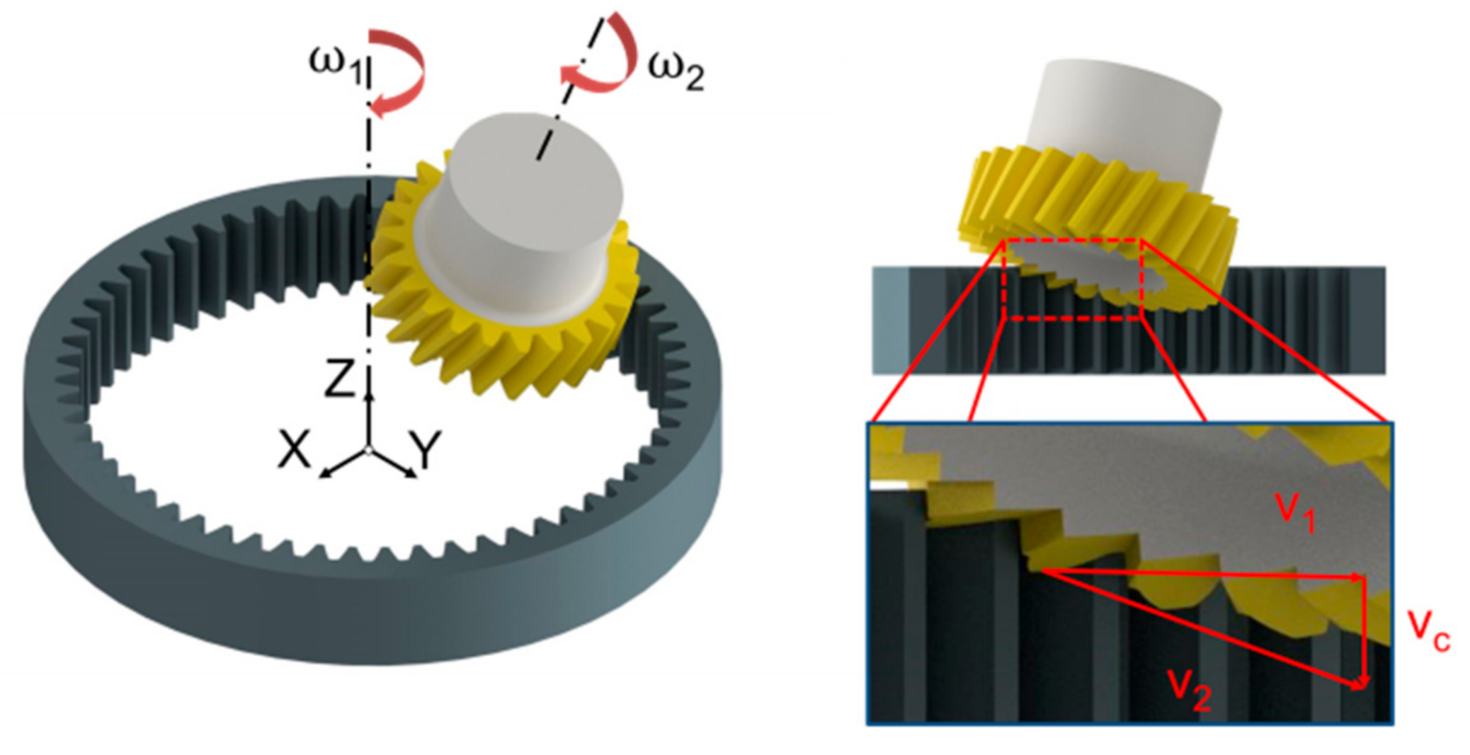
Power skiving is a complex machining process that is based on continuous generating motion between the gear and the cutting tool. The continuous nature of the process and the fact that the tool can access small bores makes it ideal for generating internal involute gears at a rate much higher than the one achieved with gear shaping. The process is illustrated in
Figure 1, as it can be seen the cutting tool and the workgear are rotating in the same direction with the tool axis positioned at an angle in relation to the axis of the workgear. In order for the two gears to mesh accurately, the tool must have a helix angle that is described in Equation (1).
where h
at is the helix angle of the cutting tool, h
ag the helix angle of the workgear and Σ the inclination angle.
The right-hand side of
Figure 1 presents the cutting speed vectors in the case of power skiving internal gears. In this process, the cutting speed due to the rotation of the workgear is presented as V
1. Because of the helix angle of the tool, an additional cutting speed exists. This cutting speed, presented as V
c, is responsible for the cutting motion in the process as it provides the main cutting speed for power skiving. By adding the two vectors, the cutting speed of the process can be calculated (V
2).
There are a series of parameters that affect the cutting process; these can be grouped into three groups, namely, the cutting tool parameters, the workgear parameters and the process parameters. The cutting tool parameters include the helix angle (hat), the pressure angle (an), the secondary rake angle (τ), the primary rake angle (γ), the number of teeth of the tool (zt) and the module of the gear (mn). The workgear parameters include the helix angle (hag), the module (mn) and the number of teeth of the gear (zg). Finally, the process parameters include the cutting speed (vc), the cutting feed (fa) and the depth of cut.
The cutting tool geometry plays a crucial role in the process stability, tool re-grindability and distribution of cutting forces. When the step grind angle is closer to zero, the tool can be easily re-ground. The cutting forces during the power skiving process are applied primarily in the direction of the axis of the tool, which can lead to bigger instability in the process due to the larger loads that are applied tangentially in the workgear. In the case of the step grind angle being equal to the helix angle of the tool, the cutting forces follow the helix angle of the gear as a primary direction. The tools in the latter case are more challenging to be re-ground as each tooth has to be individually ground. Moreover, the rake angle of the tool also plays a similar role to the direction of the cutting forces and is crucial to the chip evacuation from the gear gap.
4. Simulation Model
The calculation of cutting forces in machining processes with complex kinematics is dependent on state-of-the-art simulation codes that can predict the loading of the cutting edge. In order to assist with the development of a cutting force model for power skiving, a CAD-based simulation code was developed. The simulation code, named Skive3D, is based on a CAD environment that can generate high-quality solid models, required for the simulation. The architecture of the simulation platform that was developed is outlined in
Figure 2. The input data for the model include the geometrical characteristics of the gear and the cutting tool as well as the process parameters of the power skiving process. After the input of the data, the calculation phase can be initiated. First, the cutter profile on the rake face of the cutting tool is calculated taking into consideration all the geometric characteristics of the cutting tool. The profile is used to create the swept volume of the cutting edge in the 3D space. This volume incorporates all the moves of the cutting tool and the workpiece and is used to define, with the aid of Boolean operations, the chip and workgear geometry as seen in the right part of
Figure 2. The results of the model can be used in a series of analysis algorithms including the analysis of the workgear geometry, the analysis of the chip morphology and the cutting force component calculation.
The cutting force calculation in complex kinematic processes requires a series of multifaceted calculations due to the complex nature of the cutting process. Simple equations are not able to accurately predict the cutting forces. The cutting force calculation algorithm leverages the results of the simulation code and, in particular, the non-deformed chip geometry, to predict the loading on the cutting tool. The calculation of the cutting forces is based on the mechanistic force model presented by Kienzle and Victor [
31]. The mechanistic force equations used are only applicable in simple geometries on 2D profiles; it is therefore essential to build a series of steps to ensure the 3D chip geometry is accurately represented in the cutting force model. In order to achieve this a cutting force calculation algorithm was developed. The flowchart of the calculation process is presented in
Figure 3. The key parameters of the process used for the simulation of the power skiving process are also used in the calculation of the cutting forces. Mechanistic force models are based on the uncut chip thickness in order to calculate the cutting forces. The complex geometry of the chip does not allow for an analytical calculation of the chip thickness and width. Therefore, the chip is sectioned in a series of planes that represent the successive rake face positions during the cutting process. The section of the non-deformed chip can provide all the information about the cutting forces involved in machining at that particular rotating position. Next, the cross-section is divided in a series of elementary areas in which the elementary cutting forces are calculated. When the elementary cutting forces are calculated throughout the section, they are transformed into the local coordinate system. When the position of the rake face at that particular revolving position is known, the cutting forces can be further transformed to the tool, workgear or machine coordinate systems.
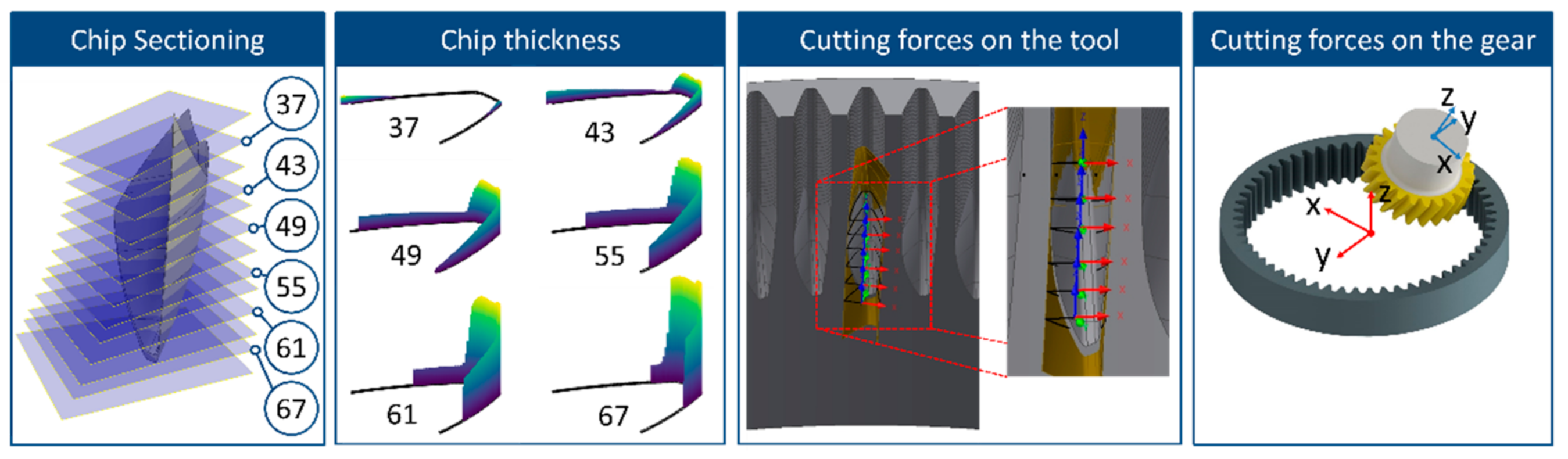
Figure 4 outlines the process for calculating the cutting force components in a chip geometry produced through power skiving. The chip geometry, as outlined in the first step, is sectioned in a series of planes. The planes are numbered based on the order that they were created. Through the analysis of the chip geometry, as presented above, the chip thickness and width were measured. The chip thickness, in a series of revolving positions, is presented in the central part of
Figure 4. As it can be observed, the head of the cutter is the part of the cutter in which the biggest chip thickness is observed. Based on the mechanistic model, this is also where the largest cutting force will be applied as the cutting force is proportional to the non-deformed chip thickness. Using the mechanistic force model, the cutting force coefficients can be calculated. The direction of the force is based on the cutting force model and has three components: parallel to the cutting speed, parallel to the cutting edge and one perpendicular to the previous two. After the calculation of the cutting forces on the cutting-edge system, the forces are transformed into the cutting-edge system. This is presented in the third section of
Figure 4. The next step in the process is the transformation of the cutting force components to the workgear coordinate system, as presented in the right side of
Figure 4.
5. Simulation Validation
The simulation code was used to analyse the power skiving cutting process. Through analysing the chip geometry, the mechanics of the cutting process and the load on the cutting edge can be analysed. In order to verify the accuracy of the simulation code, the results of Skive3D were compared with results from the literature. Using the same parameters as Jansen [
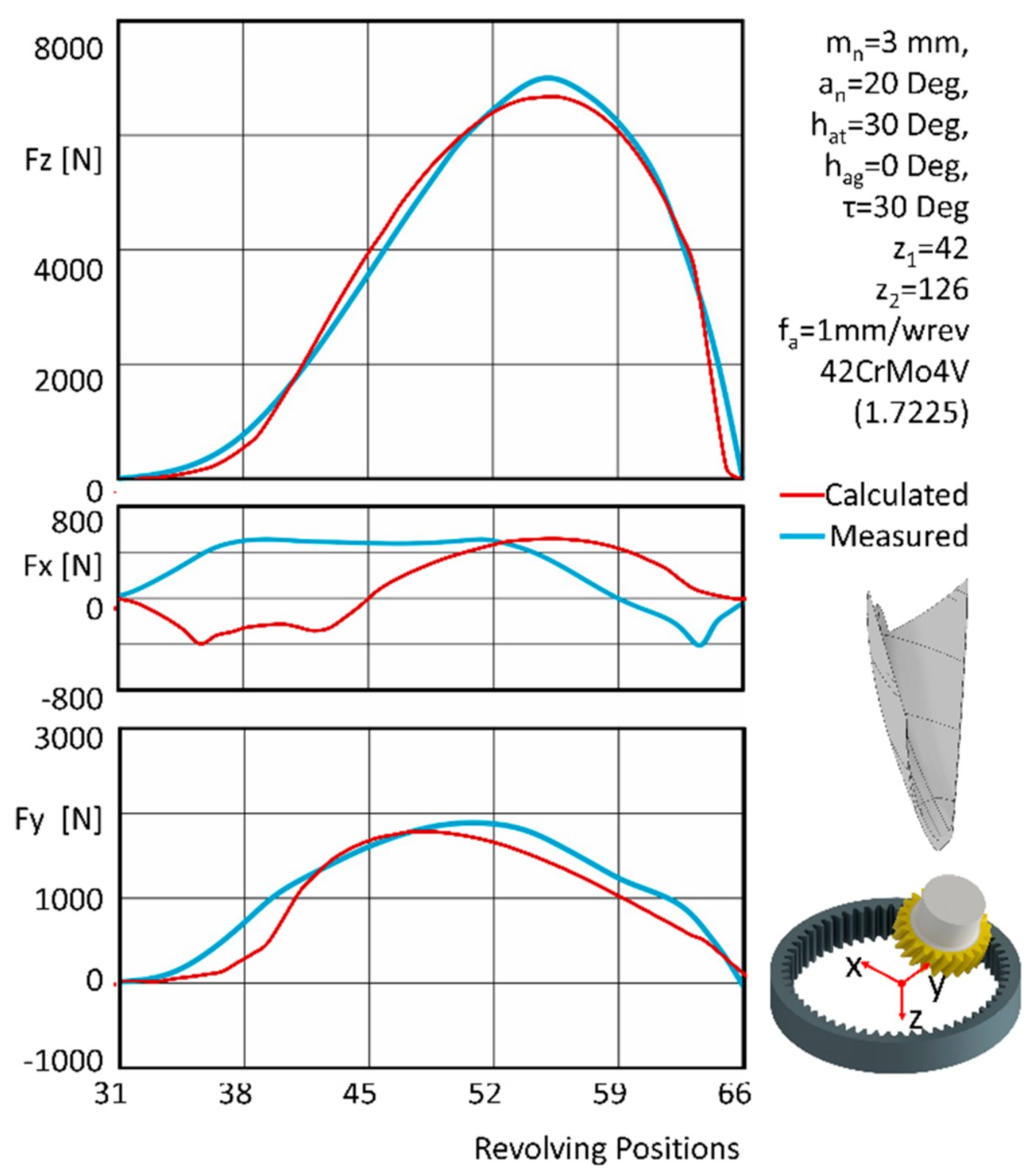
32], a set of simulations using Skive3D were performed. The trials focus on the cutting forces for machining one single gear gap, and thus, one single chip.
Figure 5 summarises the cutting forces for both the simulation and the experimental trials. As can be seen, the simulation results show good agreement with the experimental results. More specifically, the cutting forces were accurately predicted in all three directions with the Z, the main cutting force direction, showing the best agreement. The small divergence in cutting forces that was observed on the X-axis can be attributed to phenomena that are not considered by the Kienzle Victor cutting force model, such as chip collisions and tool wear. The right part of the figure also presents the solid chip geometry and the coordinate system for both the measured and calculated cutting force components. The Y-axis coincides with the centre of the machined gear gap and rotates with the gear as it is machined, while the
Z-axis is on the axis of the machined gear.
6. Effect of Process Parameters on Cutting Forces
The simulation model created can be used in order to investigate the effect of process and cutting tool parameters on the cutting forces developed during the process. More specifically, the effect of the feed rate, side rake angle and inclination angle on the magnitude of the cutting forces was studied. The maximum and minimum cutting forces were extracted for each of the simulations executed for each axis.
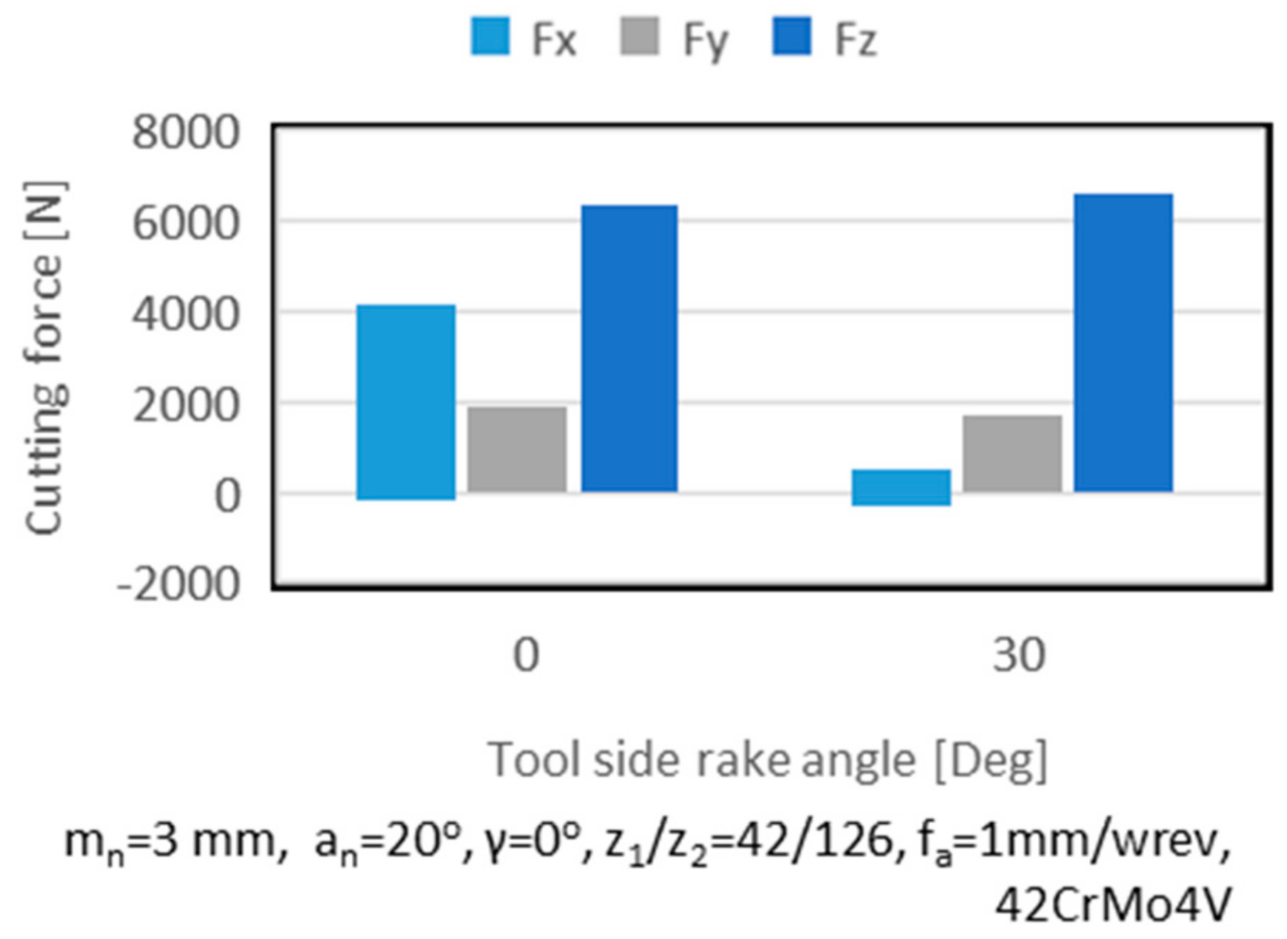
Figure 6 presents the influence of the side rake angle in the developed cutting forces. As it can be observed, the decreasing of the side rake angle led to a number of considerable changes on the cutting forces. The cutting force on the Z- and Y-axis were reduced at different levels. The force on the X-axis presented a substantial increase. As the tool side rake angle decreased the contact between the gear, and the tool subsequently increased.
The direction of the rake face of the tool had the greatest impact on the cutting force components, as the main cutting force was analysed to mainly the X and Z components that are dependent on the tool side rake angle. The chip geometry did not have a dramatic change its size; however, because of the side rake angle, the tool swept the chip in a different manner that led to the change of cutting forces.
Figure 7 presents the geometry of the non-deformed chips as well as a cross-section of the chip geometry in the indicated rake face plane.
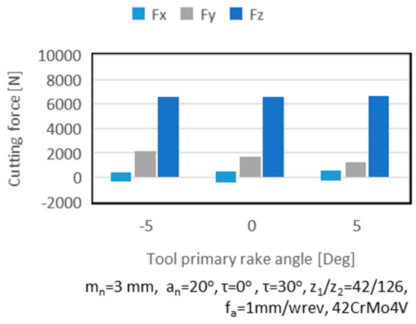
Looking at the primary rake angle of the cutting tool (
Figure 8), starting from positive rake angle values, a large positive Y and Z component cutting force can be observed. As the rake angle increases, the Y component decreases in magnitude. On the X component of the cutting forces, the maximum value increases in magnitude when the tool rake angle is decreased. As the rake angle of the tool is decreased, the rake face is presented closer to the normal surface to the Z-axis of the workgear. This leads in a smaller component of the cutting force being transformed into the Y component of the cutting force, thus reducing its magnitude.
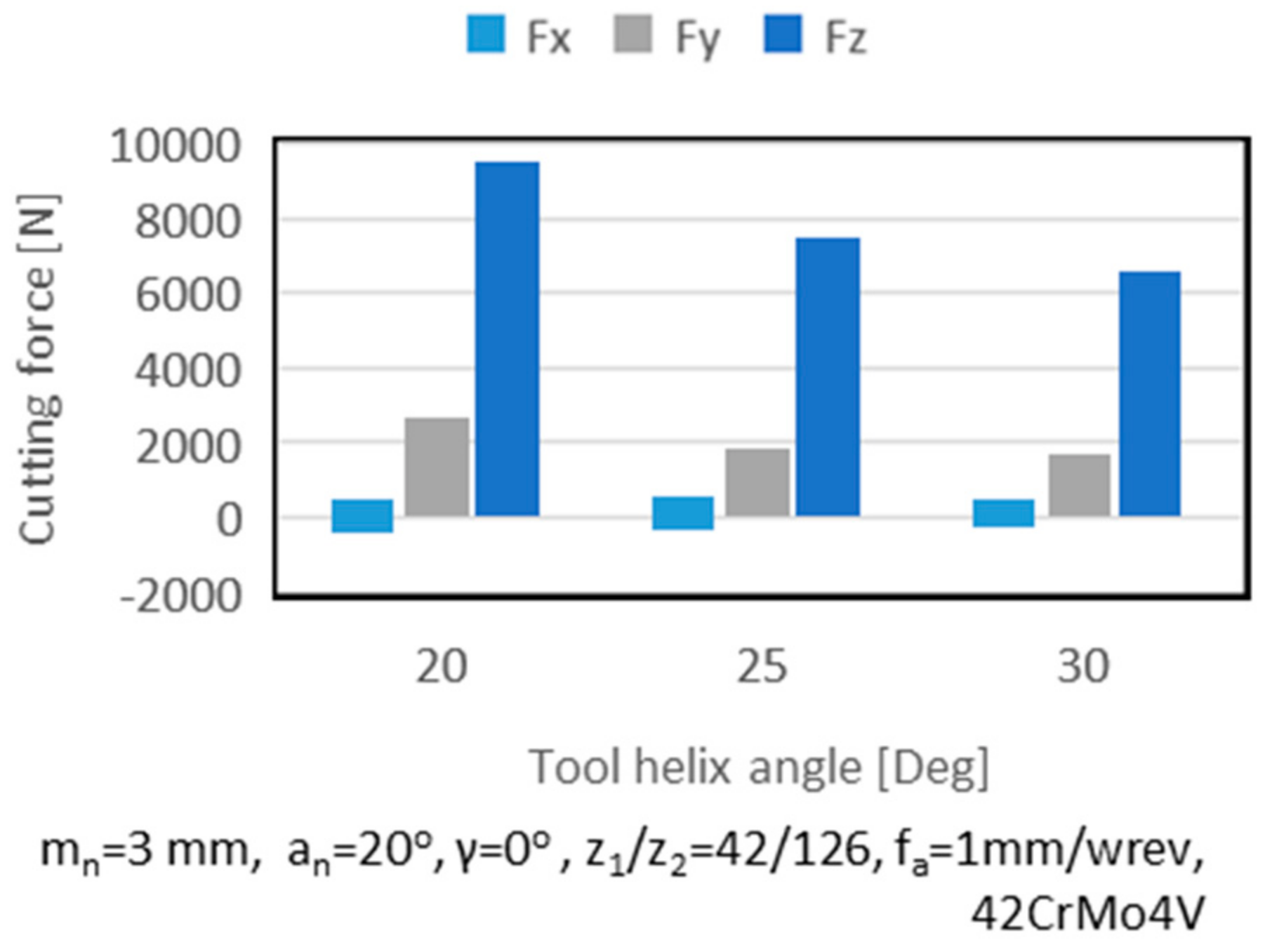
The effect of the tool helix angle on the cutting forces is presented in
Figure 9. Larger values of the helix angle lead in increased contact between the tool and the workpiece. Larger values of the tool helix angle lead in the reduction of cutting forces on the Z and Y axes. By increasing the helix angle of the tool, the cutting action takes place across a greater length and, therefore, the load is distributed over more revolving positions, as it was also reported in [
14].
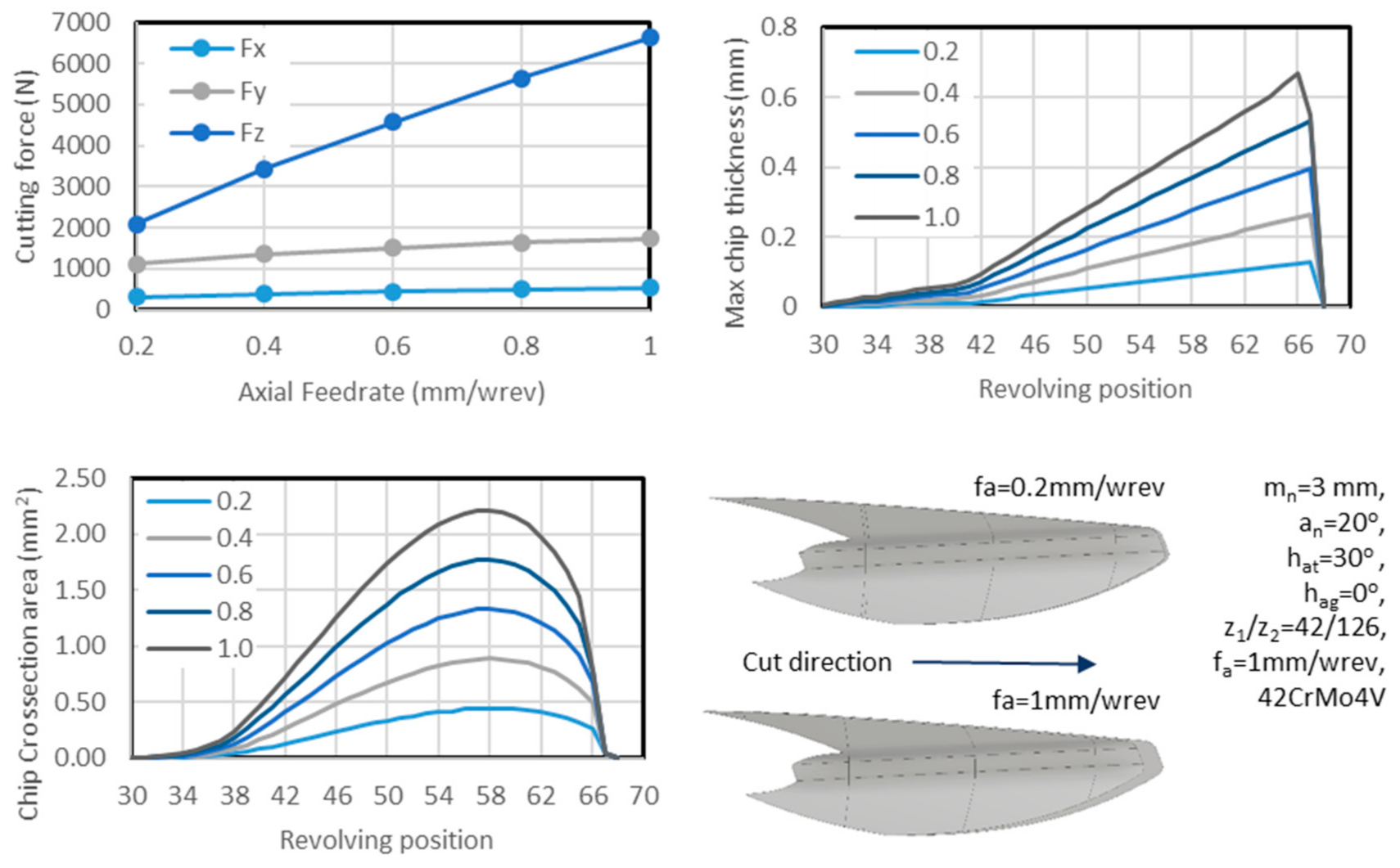
The parameter having the largest effect on the cutting force components amongst the ones available on power skiving was the cutting feedrate.
Figure 10 presents the effect of this parameter on the cutting forces on each axis for a full depth of cut machining of a gear. The cutting force on the X-axis is the maximum in magnitude force (positive or negative). As was expected, the cutting force increases with the increase of the feedrate on all three axes, with Z showing the steepest increase in magnitude. The X and Y axes show a modest increase in magnitude with the increase of feedrate. As the feedrate increases, the thickness of the non-deformed chip is increased, thus influencing the cutting force components. On the same figure, the maximum chip thickness as well as the cross-section area of the chip are presented. As it can be observed, the chip thickness increases with the increase of the feedrate, with the maximum value of the chip thickness observed in the later stages of the cut. A similar observation can be made for the cross-sectional area of the chip with the maximum value aligning with the region where the maximum force is observed. The chip morphology for the two extreme feedrates is presented on the bottom-right area of the figure. In both cases, the non-deformed chip geometry is very similar in outer form with a variation towards the later stages of the cut, where the effect of the feedrate is visible.
7. Development of Power Skiving Process Maps
Based on the requirements for increased quality of the final gear combined with a low process cost, a series of alternative strategies for machining gear geometries can be developed. Traditionally, these strategies are developed with a big experimental-based campaign that introduces a significant cost. Process simulation platforms such as the one developed in this study can be used in order to optimise the machining process while limiting the amount of experimental effort required. With the use of the simulation model developed in this research, the different machining scenarios can be investigated. In order to assist with the selection of process parameters, namely the depth of cut and feedrate, a series of process maps were developed. The framework presented in this section can be used to study the effect of different parameters on the key performance indicators (KPIs) of the cutting process including the gear quality and the cost of the process. As part of the investigation, a set of five different depth of cut strategies were examined through an automated routine in the Skive3D software. For each of the strategies, five different cutting feeds were examined.
Table 1 and
Table 2 present the case study examined as well as the strategies investigated.
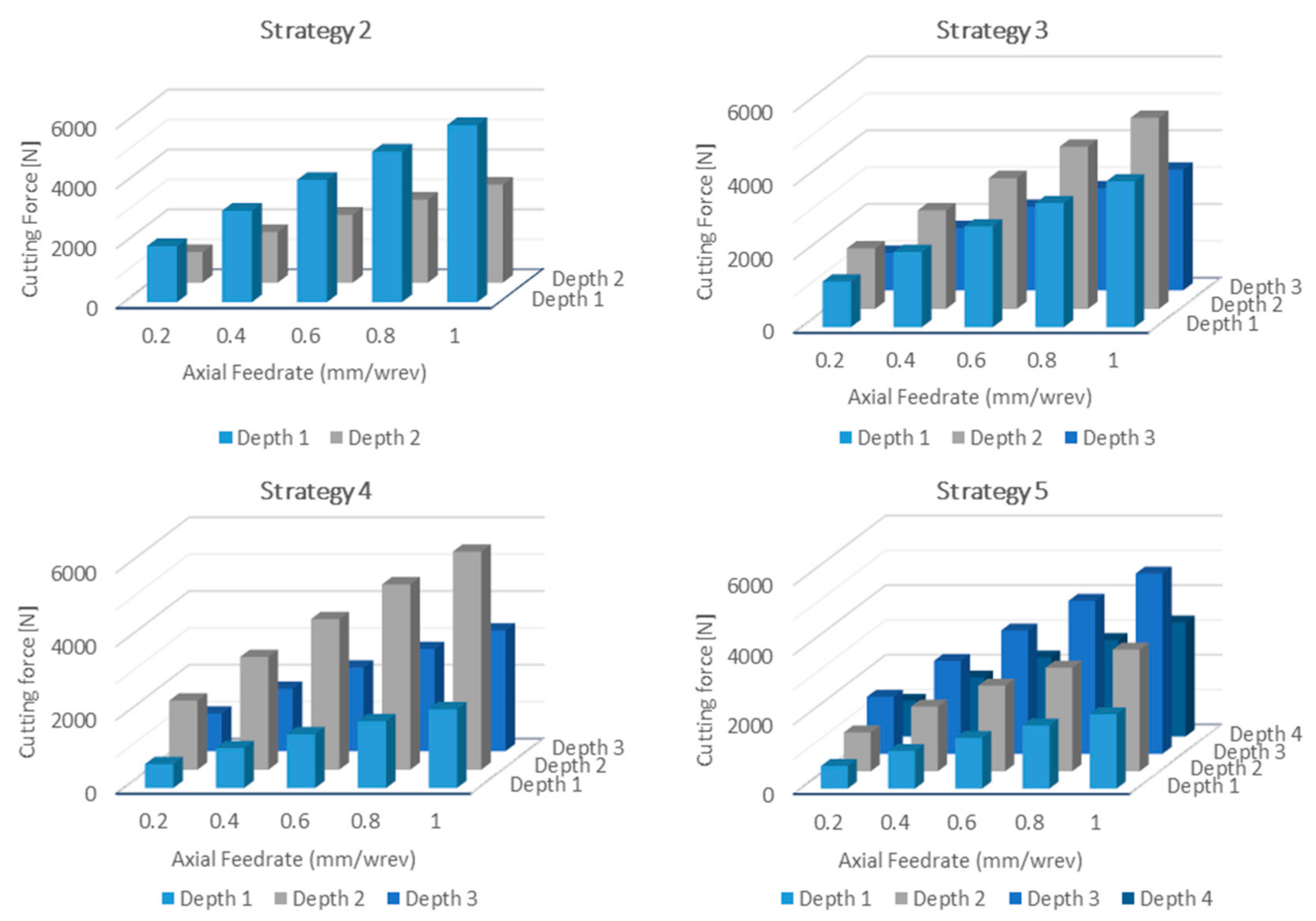
The results for strategy 1 are presented in
Figure 10. As it can be observed, high-cutting forces were predicted for the higher feedrates. Similarly, simulations were executed for all the other strategies. For each of the strategies, the maximum value of the Z component of the cutting forces was extracted since, based on the results presented in
Section 5, this was the dominant cutting force component.
Figure 11 presents the maximum Z component for each of the strategies. As it can be observed, the maximum cutting force is limited in all cases under the 6 kN mark from nearly 7 kN in strategy 1. In all four strategies, the cutting force increases the further into the gear gap the cutting tool proceeds. This is an effect of the increased contact between the tool and the workgear leading to larger amounts of chip width.
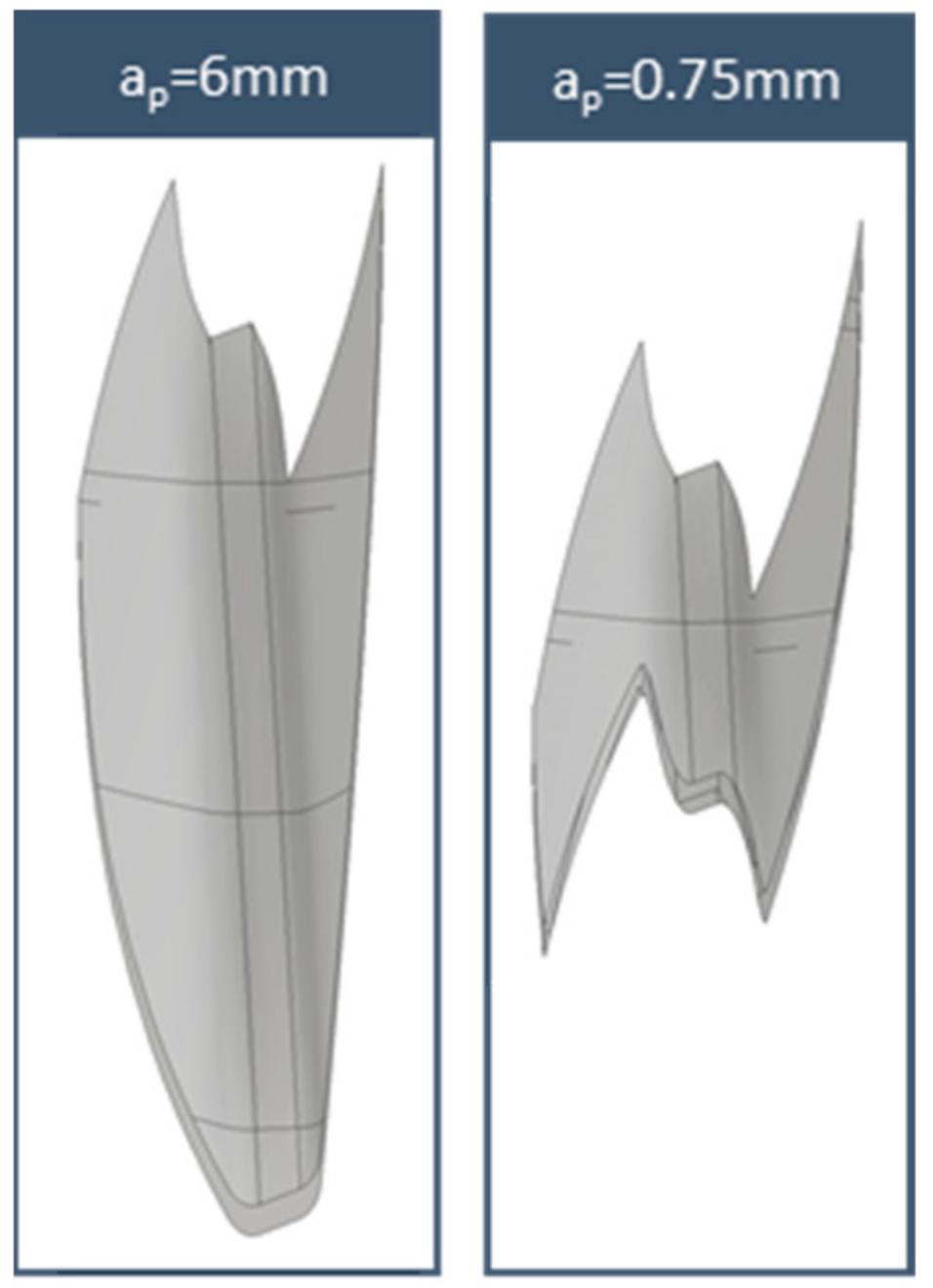
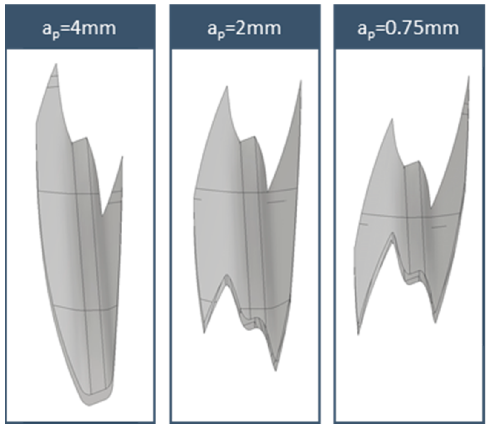
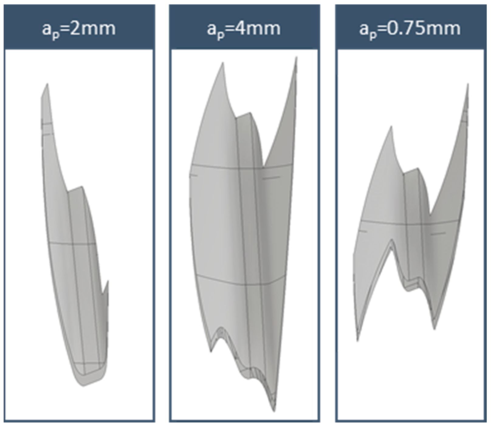
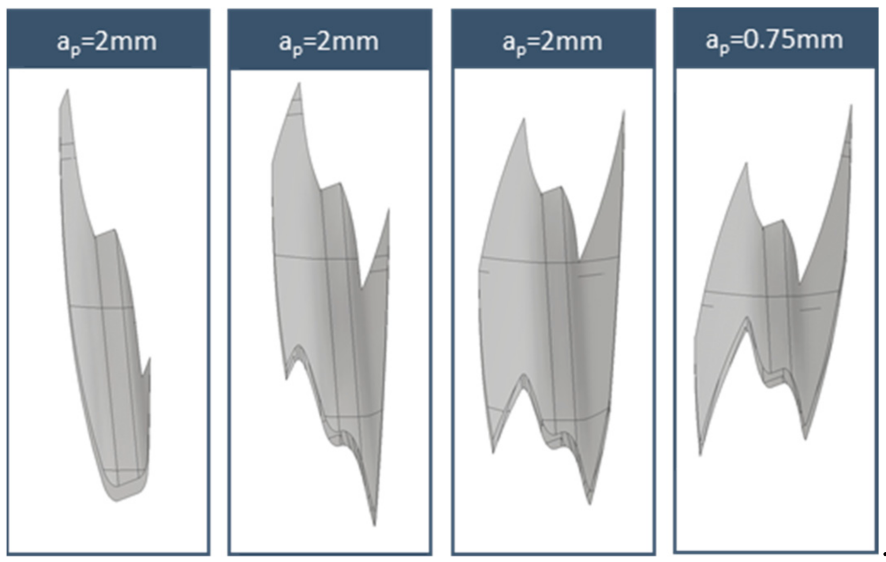
The chip geometries for each of the strategies in the midpoint of f
a = 0.6 mm/wrev are presented in
Figure 12,
Figure 13,
Figure 14 and
Figure 15. The feedrate had a minimum effect in the macro geometry of the chip, as is presented in
Figure 10. In all cases, the first depth of cut produced large chips with a general U-shaped form with the leading flank having a heavier chip load and the maximum chip thickness towards the final revolving positions. Consecutive passes tend to generate a Z- or M-type chip geometries with different widths directly linked with the depth of cut. One aspect worth noting is the increase in the chip length as the machining strategy 5 progresses.
By using the results of the five major strategies investigated, a plan for how to most effectively machine the case study geometry can be developed. In the case that the roughing passes a force, chip load limits can be established to select the most effective machining strategy. For the finishing passes, the final gear quality can be also added to support the decision-making process in order to optimise the post processing of the gear. For instance, if the force limit for the Z-axis is set at 4 kN, then for strategy 1, the feedrate selected should be 0.6 mm/wrev and 1 mm/rev, and for strategy 5, the optimal strategy would be 1, 1, 0.6 and 1 mm/wrev.
8. Conclusions
The research presented in this paper focused on the creation and validation of a CAD=based model for the prediction of cutting forces in power skiving. The model uses the non-deformed chip geometry to understand the chip characteristics and a mechanistic cutting force model to predict the resulting cutting forces. The cutting force model was verified with experimental data for single gear gap machining. This allows for a superior validation of the force model, as measurement noise and other effects (such as tool wear, coolant and chip collisions) can be minimised. The results of the validation showed that the maximum error of the simulation model was less than 5% with respect to the maximum and minimum values predicted, with the form of the cutting force loading also accurately predicted. The effect of process parameters on the cutting force magnitude was investigated. The tool helix angle and side rake angle were found to have the greatest impact on the cutting force direction and magnitude. The minimum loading on the tool was observed at 30° for the side rake and 30° for the helix angle. As expected, the feedrate also plays a critical role in the magnitude of the cutting forces. Based on the simulation model, a novel way of creating process maps and down selecting the optimum cutting conditions is presented. Using the framework presented, end users can select the best combination of the cutting parameters, namely depth of cut and feedrate, in order to have a cost-effective and productive process.


