Article

A Synergy of Innovative Technologies towards Implementing an Autonomous DIY Electric Vehicle for Harvester-Assisting Purposes

by
Dimitrios Loukatos
1,*,
Evangelos Petrongonas
2,
Kostas Manes
3,
Ioannis-Vasileios Kyrtopoulos
1,
Vasileios Dimou
1 and
Konstantinos G. Arvanitis
1
1
Department of Natural Resources Management and Agricultural Engineering, Agricultural University of Athens, 75 Iera Odos Street, Botanikos, 11855 Athens, Greece
2
School of Electrical and Computer Engineering, National Technical University of Athens, 15780 Athens, Greece
3
Department of Informatics, University of Piraeus, 18534 Piraeus, Greece
*
Author to whom correspondence should be addressed.
Machines 2021, 9(4), 82; https://doi.org/10.3390/machines9040082
Submission received: 11 March 2021 / Revised: 15 April 2021 / Accepted: 16 April 2021 / Published: 19 April 2021
(This article belongs to the Special Issue Intelligent Mechatronics Systems)

Abstract

:
The boom in the electronics industry has made a variety of credit card-sized computer systems and plenty of accompanying sensing and acting elements widely available, at continuously diminishing cost and size levels. The benefits of this situation for agriculture are not left unexploited and thus, more accurate, efficient and environmentally-friendly systems are making the scene. In this context, there is an increasing interest in affordable, small-scale agricultural robots. A key factor for success is the balanced selection of innovative hardware and software components, among the plethora being available. This work describes exactly the steps for designing, implementing and testing a small autonomous electric vehicle, able to follow the farmer during the harvesting activities and to carry the fruits/vegetables from the plant area to the truck location. Quite inexpensive GPS and IMU units, assisted by hardware-accelerated machine vision, speech recognition and networking techniques can assure the fluent operation of a prototype vehicle exhibiting elementary automatic control functionality. The whole approach also highlights the challenges for achieving a truly working solution and provides directions for future exploitation and improvements.

1. Introduction

Taking into account the recent United Nations (UN) estimations, the world population will be more than 9.6 billion by 2050 [1]. For this reason, according to Food and Agriculture Organization (FAO) [2], in order to cover the nutritional needs of the constantly growing world population in the twenty-first century, agricultural productivity should be increased by 60%. This important goal has to be achieved despite the fact that the resources being required become fewer and fewer, in both quality and quantity. Global climate change and the increased pollution levels make this situation even more intense [2]. To tackle these issues, the sector of agriculture has to become more productive and with a smaller environmental footprint, by successfully exploiting a variety of emerging technologies.
Thankfully, the advances in Information and Communication Technologies (ICT) allow for many significant improvements in agri-production [3], and thus Robotics and Autonomous Systems (RAS) technologies could positively contribute to the transformation of the agri-food sector [4,5,6,7] and provide systems capable for real-time processing and analysis [8]. The use of robots in agriculture can also tackle the lack of labor for the harsh part of the job and create jobs for more specialized ICT technology personnel. Most of the recent trials to create efficient agricultural robots are focusing on weeding, harvesting, crop scouting and multipurpose use, due to their challenging character and their quick return of investment potential [9,10]. As the large versions of advanced agricultural machines are quite expensive and thus quite unreachable by many farmers having a limited financial potential [11], smaller autonomous machines can be hired to accomplish the farm tasks [12,13], probably working in a co-operative manner [14,15]. Smaller units also reduce the unwanted soil erosion and compaction effect [16] and provide better maneuverability between the plantation lines. Furthermore, if these machines are electric, the polluting residues of their petrol counterparts are lacking. In addition to that, electric robotic vehicles can minimize their energy demands in-line with the directions for sustainability, by exploiting solar panel units and batteries for their operation. The small agricultural robots can be seen as simplified versions of human companions, able to perform useful operations, in the sense of assistive robotics which is a promising sector especially for healthcare cases [17]. This aspect becomes even more important taking under consideration the World Health Organization (WHO) report [18], finding that one in seven people experience disability to some extent, and apparently, many of them are farmers. Indeed, the perspectives of the smart electric robots involved in agricultural tasks are also very promising, according to recent analysis findings [19], following the general upward trend. According to the International Federation of Robotics (IFR) there is a continuously growing interest in robots, covering a wide range of human activities, as reflected by the vast recent increase in the global robotic market sales, while the long-run perspectives of robots remain excellent, for a variety of reasons, from sociological to technological ones, that are accelerated by the COVID-19 pandemic [20,21]. Professional service, personal assistance robots and robots for logistics are included in this glorious list.
Typically, the larger commercial robotic vehicles are exploiting a fusion of data provided by quite expensive sensors of different types, like accurate Global Positioning Systems (GPS) and cameras with machine-vision capabilities, for better localization and path planning in order to perform precise operations [22]. Aiming to achieve better sensor characteristics, this selection of components can be very costly. This cost can be reduced significantly by choosing cheaper parts and counterbalancing any possible lack in accuracy with a more efficient synergy among them and more sophisticated algorithms. Towards this direction, encouraging results are provided, even for demanding systems like road vehicles [23], through machine learning techniques. A very promising fact is that the boost in the electronics industry resulted in a plethora of devices of amazing characteristics that are offered, day-by-day, at very affordable prices. Many innovative systems are now widely available and cost-effective enough to support laboratory-level trials [24,25,26] to create robots of convincing role and size, combining elements far less expensive than the out of the box Real-Time Kinematic (RTK) GPS and the Near Infrared Imagery (NIR) and stereovision cameras that are used in the commercial solutions. Added to this, not all agricultural robotic operations are extremely complex demanding high precision equipment. For instance, the fruit transportation process is much simpler than the fruit collection process itself, as the latter has to take into account the properties of the fruit to be picked from the tree and provide a set of precise movements so as not to damage the plant or the fruit. On the other hand, despite the fact that the fruit transportation from the plant to the cargo truck is a simpler process, it is not a less important one, as any potential damage during this transportation could have a negative impact on the final fruit quality [27]. The fruit transportation process remains labor-demanding and harsh to be accomplished by humans, who could be better hired to collect the fruits.
In this context, this article highlights the experimental efforts intending to achieve a balanced synergy of a diverse set of quite inexpensive (and thus not very precise) components like simple materials, widely available electronic parts and gluing software exploiting with Artificial Intelligence (AI) capabilities, in order to create an autonomous robotic vehicle for harvester-assisting purposes. Typical GPS and orientation sensors can be combined with hardware-accelerated image and voice recognition techniques to provide a cost-effective autonomous operation. The whole arrangement can achieve satisfactory results, for a specific set of cases and assumptions. The whole approach is in-line with the DIY (Do-It-Yourself) philosophy, which is an effective method to serve the educational goals of the technical universities, at reduced cost levels. The gap in size, cost and complexity, between educational robotic platforms, like the ones described in [25,26,28,29], and commercial agricultural robotic solutions like the ones described in [13,30] is not unbridgeable, the success story of the Thorvald robotic platform [31] proves that, as their inventors created later a successful company offering multipurpose agricultural electric vehicles with very good perspectives [32,33].
Apart from this introductory section, the rest of this work is organized as follows. Section 2 highlights the robot’s functional requirements as well as the methods and the materials selected to facilitate the deployment process. Section 3 provides characteristic design and implementation details. Section 4 is dedicated to characteristic results and comments. Finally, Section 5 contains conclusion remarks and plans for the future.

2. Functional Requirements, Methods and Materials

The autonomous vehicle to be implemented should be able to carry a typical fruit transport pallet bin (also known as crate) at the speed of a walking man and thus it can be viewed as just a bin on wheels that is able to move in a smart manner. The basic vehicle construction should be simple, lightweight and cheap enough and should match the physical dimensions of the carrying typical fruit transport bin. The robot should have the ability for real-time processing and analysis, a critical factor towards any successful automation activity in agriculture [8]. In-line with the specification directions described in [4], the main duties of the robotic vehicle to be implemented can be summarized as follows:
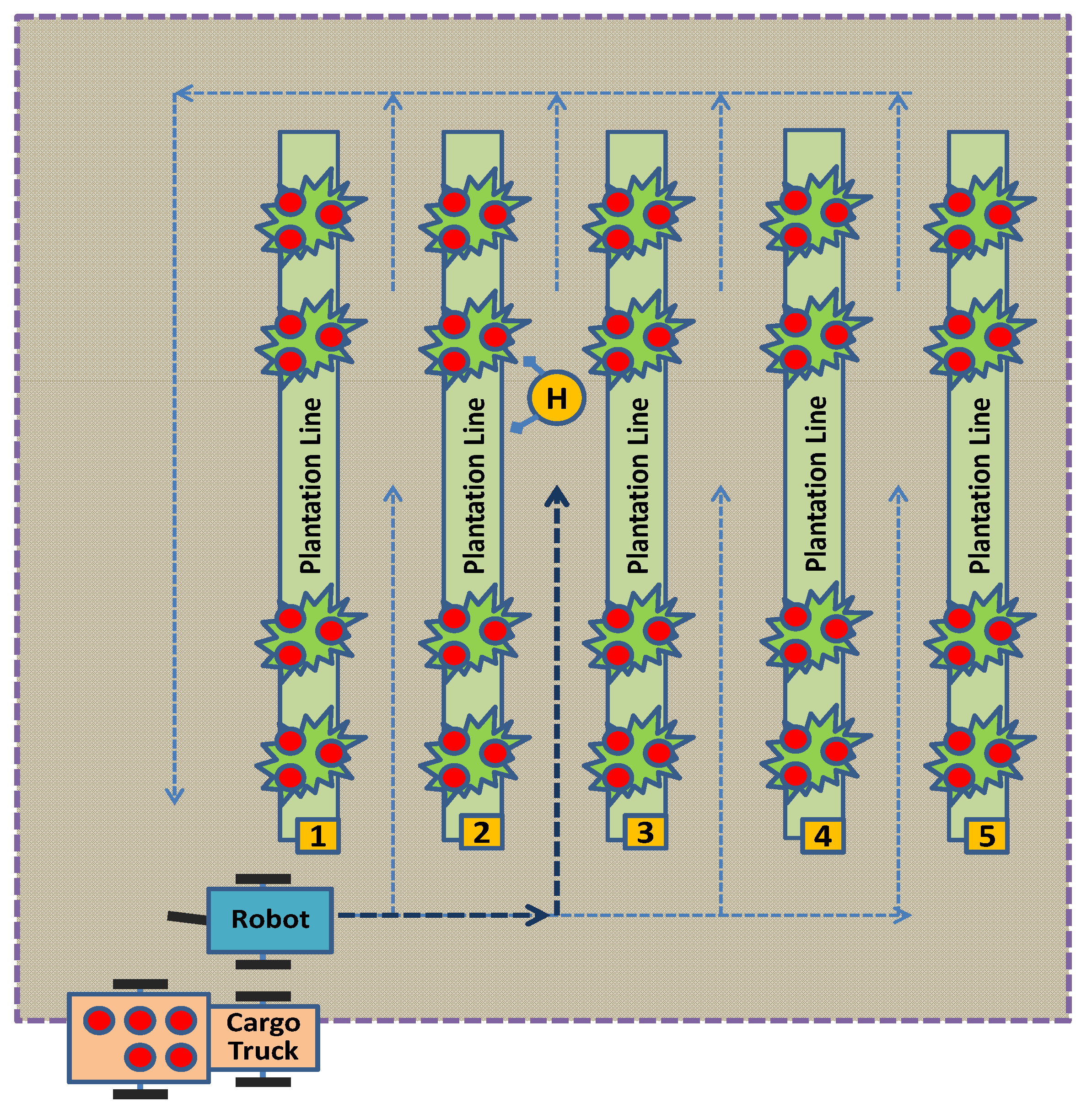
  • To start from a specific location and reach the location of a specific harvester, in the field, between the plants.
  • To follow a specific harvester during its work, so that the latter is able to put into it the fruits being collected.
  • To recognize simple predefined voice commands, in order to stop to a specific location, to start/restart following the harvester, to go to the truck when full.
  • To repeat the whole process, i.e., to go back to the harvester’s location from the truck’s location and so on by following the narrow paths surrounding the field or moving between the plantation lines.
  • To provide health status indication messages (i.e., battery voltage low alarm) and perform the necessary emergency actions (e.g., to return to the truck or to start beeping).
  • To continuously report its location for testing purposes and provide efficient manual overdrive alternatives, e.g., when a sensor malfunction case is scanned.
  • To operate on a local (off-line) basis without heavy dependencies on cloud-based elements (i.e., accessible via the Internet). The latter option can be implemented for debug/emergency cases only.
Quite simple microcontroller elements like the arduino uno [34], the raspberry pi [35] or the wemos [36] board, that exhibits middle-range potential, can be combined with affordable sensors like Inertial Measurement Units (IMUs), like the LSM9DS1GPS module [37], cameras and some extra cheap components, in a manner that can provide promising results. More specifically, the GPS units to be used are expected to provide accuracy near to 1m (as they are not RTK capable ones) and thus the fusion with data provided by other types of sensors (e.g., cameras, IMUs) will be necessary to guarantee a fluent operation. This GPS accuracy, although not perfect, is still promising and really achievable by the new generation of u-blox M8 and mainly M9 receivers [38] and the pairing multiband antennas. The presence of compact innovative modules like the navio2 navigation system [39] or the pixy2 camera [40] with its embedded object identification and line-following features can drastically facilitate the whole deployment process. The presence of the raspberry pi allows for advanced processing, using packages like the OpenCV [41] image/video processing environment. The ability of the robot to intercept simple voice commands is a welcome feature that allows for not disrupting the farmer’s hands from the harvesting process. Furthermore, powerful hardware accelerators are now offered at very affordable prices making traditionally computationally “heavy” tasks, like machine vision, lighter and faster than ever before. The manufactures of these modules are providing the necessary software drivers, application programming interfaces (APIs), and well-documented examples in order for a tailored software version to be quite easily deployed, using a wide variety of programming tools, ranging from well-known textual environments, like C or python, to visual block tools, like ardublock or MIT app inventor for the less experienced users.
In order to guarantee a fluent operation and drastically facilitate the methods for achieving it, additional information should be accessible by the robotic vehicle. More specifically the worker should be equipped with a mechanism reporting its location in a typical GPS data format. The same functionality is important to be supported by the tractor/truck where the fruit bins will be finally loaded. The interoperation of the diverse components should be done at comparatively long distances (i.e., of the order of 1km) and in the presence of substantial electromagnetic noise, i.e., provided by the engine of the tractor/truck. The plantation lines can be tagged using bar code labels and an initial path-training stage is necessary, in order to fluently assist the robotic vehicle in its localization movements. The map of waypoints to be trained should be of two-dimensional nature, for simplicity reasons. A typical arrangement for all the components being necessary for the discussed fruit transport process is depicted in Figure 1.
The whole fruit transport process from the harvester to the truck would last several hours and thus the robotic vehicle should be equipped with large and easily replaceable batteries. The assistance of solar panels, either fixed on the robot or lying in a nearby charging station could minimize the environmental impact of the proposed solution. The whole sensor information fusion, including machine vision techniques, voice recognition and GPS data processing, as well as the corresponding localization and path planning decisions, should be fast enough (i.e., 2–4 times per second) to lead to a responsive vehicular platform and to eliminate the energy spent for path correction actions.

3. Design and Implementation Details and Challenging Trade-Offs

The process of implementing a prototype harvester-assisting vehicle should meet an amount of diverse requirements and thus a careful combination of features should be made to meet the various operational specifications. In order for the implementation details to be properly highlighted, the separate functional parts of the discussed robotic vehicle are thoroughly described.

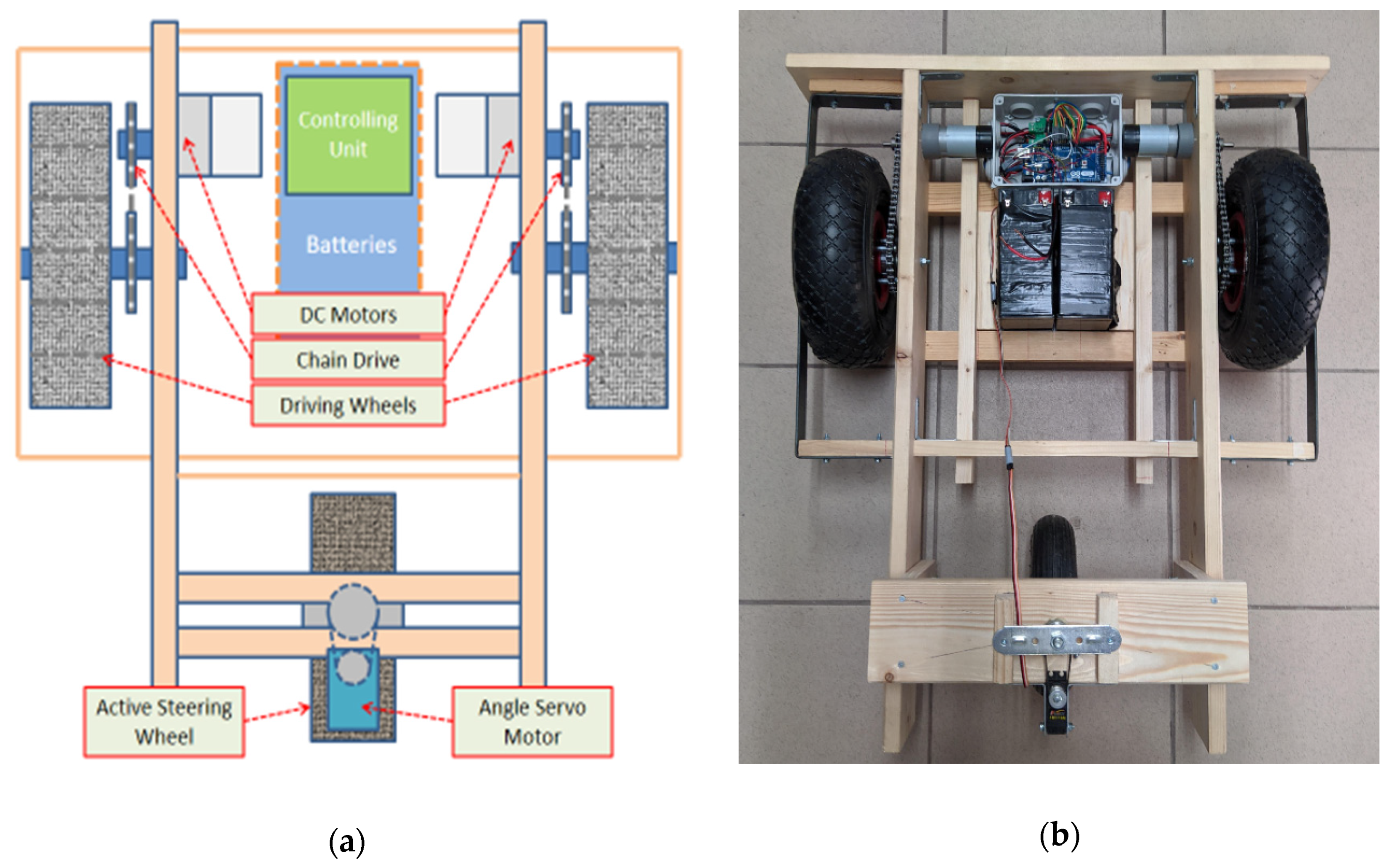
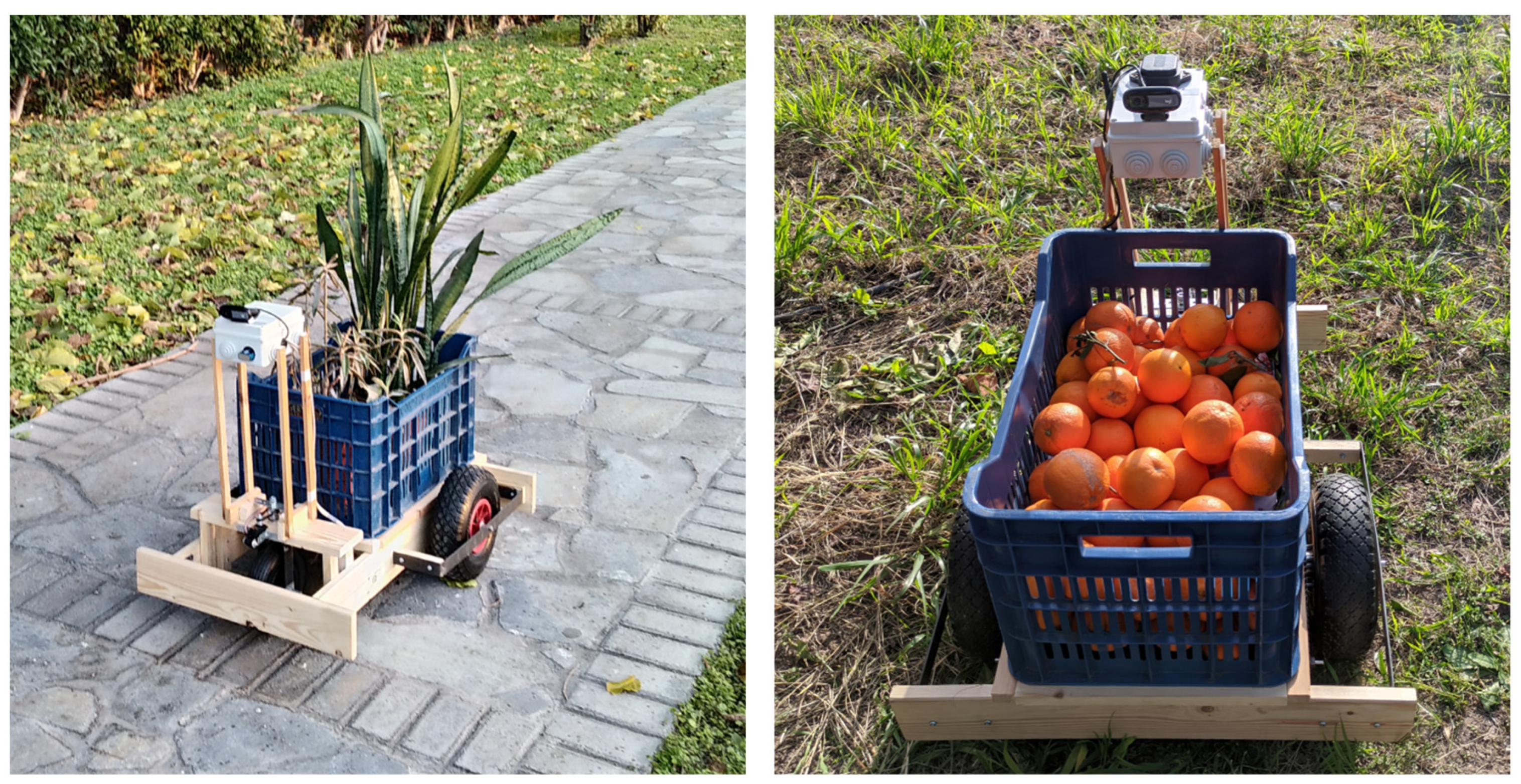
3.1. Electromechanical Layout

This prototype harvester-assisting vehicle, is made of wood and metal, to combine lightweight construction, robustness and fast deployment by quite inexperienced personnel using simple tools. The whole process follows and extends the methods described in [25,26]. Indeed it is a three-wheel layout to eliminate the need for a suspension mechanism. The pneumatic tires being used (of 26 cm, in diameter) are thick and wide enough to absorb the terrain anomalies and withstand mud. Two of the wheels, one at each side of the robot, are slightly larger and connected with a pairing independent electric motor, equipped with a chain drive mechanism. The third wheel (of 20 cm, in diameter), in the middle-rear part of the vehicle, is connected with an angle servo unit through a belt-drive, to provide active steering functionality.
The motors were selected so as the robot speed to be similar to the one of a slow-walking man on the surface of an agricultural field path. It must be noted that, as the two side wheels are capable of differential steering functionality, the third wheel could be a simple caster (free) wheel. Nevertheless, the addition of the active steering method provides better maneuverability and improves the ability to follow a specific path, despite the presence of small obstacles and thus leaves less work for the underlying speed control mechanism. The gearbox-equipped motors are rated as 150 rpm units and they have a stalling torque of 75 kg and a stalling current of 20 A. The latter characteristic means that, during normal operation, even under heavy load, the current will not exceed the 4–5 A level per each motor. The chain drive system reduces the rotation speed by a factor of 3, increasing in parallel the torque by the same amount. The motors are also equipped with a speed feedback mechanism based on hall sensors to support speed stabilization functionality. The basic electromechanical layout of the harvester-assisting vehicle (i.e., both the initial design and the implementation outcome) is depicted in Figure 2.
As the vehicle is capable of hosting one typical fruit transport plastic pallet bin, its width is 70 cm approximately and its length is 80 cm. The robotic vehicle weighs 15 kg approximately, with a pair of batteries to be included. The selection of all hardware components is intended to minimize the size and the cost and maximize the reusability of materials and electronics. Typically, two deep discharge acid-lead battery units of 7.2 Ah capacity, at 12 V, weighing 2 kg each, provide the necessary power for the robot. A suitable switching DC-DC step-down voltage converter, with additional current-limiting functionality, drains energy from the batteries and supplies the sensitive electronics that control the robot. Two 3-cell lithium-polymer batteries of 4000–5000 mAh each, can also provide a lighter energy source alternative. There is also provision for a solar panel unit to be hosted on the robot, typically of 10–15 W, which is able to supply 0.7–0.8 A, approximately, at ambient sunlight conditions. The latter unit adds 1.25 kg to the whole construction.

3.2. Low-Level Control Equipment and Functions

By following the well-documented implementation paradigm of previous university trials [25,26], the prototype harvester assistant robotic vehicle incorporated basic automatic control functionality (in terms of speed and direction stabilization) based on data fusion of signals provided by the hall sensors accompanying the two driving motors and an IMU and compass sensor element. In order for the vehicle to be tolerant to small obstacles and not to deviate from its route, the third wheel, instead of being a simple free caster wheel, is connected to an angle servo mechanism to support active steering. The axis of this latter servo motor is equipped with a potentiometer resistor to provide angle feedback information. An arduino unit (initially a uno and later a mega unit, for improved connectivity options) tackles the abovementioned low-level control tasks and also intercepts and parses more sophisticated directions coming from the high-level control equipment unit. Indeed, further assistance is provided by diverse techniques, implemented using the high-level control elements described in Section 3.3, Section 3.4, Section 3.5 and Section 3.6. The discussed arduino for the low-level functions is also responsible for reporting (or storing) detailed health status data related to the operational status of the robot. There is also provision for a manual overdrive alternative. The vehicle’s geometry, in order to improve efficiency, utilizes a special calculation method that provides separate target speed values, for the left and the right side wheels, and a corresponding turning angle value, for the third active steering wheel. Upon calculation of these target speed values, the low-level speed control mechanism only has to follow these targets, for the left and the right wheel separately. The third active steering wheel is simply forced by the dedicated servo motor to reach the specific turning angle. The underlying robot’s geometry-related calculations allow for the vehicle to turn at a given speed, following an arc belonging to a circle of a preferred radius. The necessary information to understand this calculation mechanism is depicted in Figure 3.
Let vo be the desired (and known) speed (i.e., the linear velocity) of the outer wheel. Let ro and ri be the external and the internal radius of the circles followed by the outer and the inner wheels during this turn. The difference between ro and ri is the inter-wheel distance d, which is known. The distance between the middle point of d and the third wheel is also known and equals l. It is easy to prove that the angle to turn the third wheel θ, equals the angle at the center of the cycles, φ. The latter angle, φ, can be easily computed as the arctangent of (l/(ri + d/2)), and thus:
θ = arctan (l/(ri + d/2)),
As both the outer and the inner wheels have the same orbital angular velocity over the vertical axis (i.e., around the center of the turning circles of radius ro and ri, respectively):
vo/ro = vi/ri or vo/(ri + d) = vi/ri or vi = vo · ri/(ri + d),
where vo and vi are the linear velocities that correspond to the outer and the inner driving wheels. According to this arrangement, while turning, the velocity of the outer wheel remains equal to the one of the whole vehicles just before steering (i.e., the common speed of both wheels).
In recapitulating, both θ and vi can be easily computed for a given geometry by the l, d and vo quantities and thus provide a “smooth” turning process for the robotic vehicle. Table 1 contains the proposed values being calculated for the vi and θ quantities, as a function of the inner radius, ri, for a given vehicle’s reference speed, vo = 1 m/s and a given geometry with d = 0.5 m and l = 0.4 m. Small deviations/truncations are expected due to the limited accuracy of the 16-bit arithmetic and the 8-bit pulse width modulation (PWM) timers of the processor used by the low-level control mechanism.

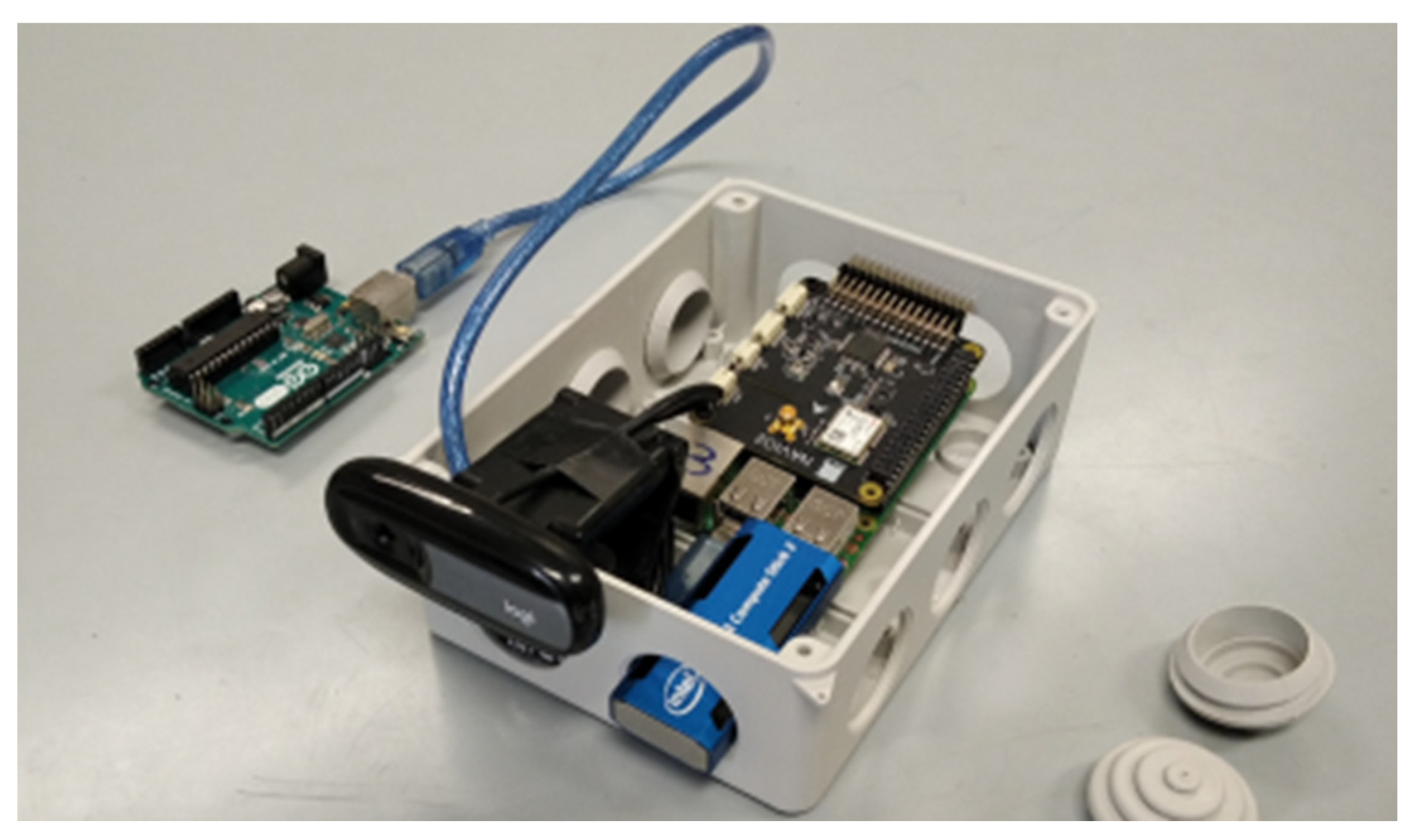
3.3. Overview of the High-Level Control Equipment and Functions

The proposed robotic vehicle high-level architecture, exploits, in a simplified manner, some of the autonomous vehicle perception and localization methods that are fluently explained in a recent and quite complete review work [23]. More specifically, assisted by a fusion of GPS and IMU/compass data, the necessary input is provided to a map-matching and path-planning localization algorithm, using pre-stored map information, known as “a priori maps”. At the second level, visual odometry data (i.e., through camera calibration, image acquisition, feature detection, feature matching, feature tracking, and pose estimation) refine the localization decisions of the robotic vehicle towards the harvester or the truck targets, a mechanism that becomes dominant when close to the targets. At the third level, a voice command option is activated in order to facilitate the cooperation between the farmer and the self-powered transportation pallet bin. The high-level engine is called to make navigation decisions assisted by GPS data, machine vision data, speech recognition data, plus an optional set of auxiliary sensing indications. All these complicated and demanding tasks are left for the more powerful raspberry pi single board computer [35] (more specifically, a model 3 B unit). The raspberry pi has further assistance in its mission by some new-coming and quite powerful gadgets, like the Intel Movidius Neural network Compute Stick 2 (NCS2) [42] and the ASUS AI Noise-Canceling Mic Adapter [43].

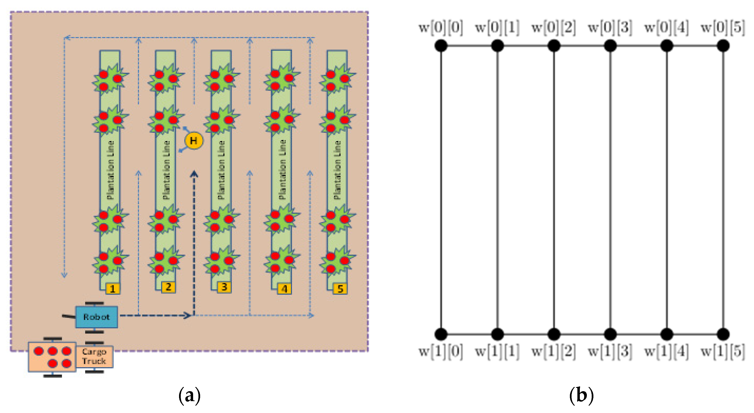
3.4. High-Level Control Equipment and Functions (Path Planning)

Before the robotic vehicle starts its harvester-assisting duties, the working area should be mapped, in a draft manner, using equipment similar to a GPS tracker, which is available at no extra cost. Indeed, this tracking functionality requires a quite accurate GPS unit and memory storage, resources that are provided by the equipment specifications given in Section 2 for the participating entities (i.e., for the robotic vehicle, the harvester and possibly for the track). Amongst these entities, the robotic vehicle is expected to have the most precise variant and thus, this equipment module (ideally detachable) should be preferred for the mapping process. The farm’s perimeter has to be covered and the entry point of each plantation line has to be marked (and numbered). By this initialization process, an “a priori” map of the field area is generated, stored and communicated among the participating entities. The farmer can also indicate the number of each entry point (lane start) or scan it from a corresponding label being there using a barcode scanning application/device This initial arrangement, that for the moment has to be completed by manual assistance, permits to devise a simple and efficient path planning algorithm for the vehicle, as the field is modeled by a grid consisting of two opposite horizontal line segments, called sides, and N vertical line segments, called lanes. Lanes represent the space between neighboring plantation lines, whereas the two sides along with the two outer lanes represent the perimeter of the field. For better understanding, the left part of Figure 4 depicts an indicative example of a field area and the main entities participating in the harvesting process, i.e., the track, the robotic vehicle and the harvester. The right part of Figure 4 depicts the corresponding to the field map model.
According to this model, the vehicle is allowed to move along the sides and lanes in order to move from any point on the grid to any other point on the grid. Each intersection point of a side and a lane defines a waypoint. Waypoints are stored in a 2-dimensional array w. In particular, the i-th side, where i = 0,1, is a line segment with endpoints w[i][0] and w[i][N − 1], whereas the j-th lane, where j = 0,1,…, N − 1, is a line segment with endpoints w[0][j] and w[1][j]. Note that the opposite side can be determined by the addition of mod 2.
The lat/lon coordinates of the waypoints are stored in a text file, where the j-th line contains four space-separated values corresponding to the lat/lon coordinates of w[0][j] and w[1][j]. This text file is created once for every different field, before the robotic vehicle starts its harvester-assisting duties. This is a process that can be easily carried out by the farmer, without any assistance, by marking the coordinates of the waypoints, using a GPS device. This equipment is available for the harvester, and is part of the system on the robot. For this reason, it is available at no extra cost. More specifically, the farm’s perimeter has to be covered and the entry point of each plantation line has to be marked (and numbered). By this initialization process, an “a priori” map of the field area is generated, stored and communicated among the participating entities. The farmer can also indicate the number of each entry point (lane start) or scan it from a label being there using a barcode scanning application/device.
In a more general setting, where sides and lanes are not straight lines, a list of additional points between successive waypoints can be stored so that the vehicle moves from one waypoint to the next by following this sequence of points instead of a straight line. In this way, the vehicle is able to stay on the grid and avoid collisions with the plants, trees, or any objects outside the grid.
Given the above mathematical abstraction for the field, the problem of path planning is stated as follows: “Given two points A and B on the grid, find a sequence of waypoints defining a possibly shortest path from A to B, which stays on the grid”. In order to solve this problem, we first make three assumptions:
  • Point A, if not on the grid, it is almost on the grid, i.e., its distance from a side or lane is negligible.
  • Point B may be far from any side or lane, but another point B’ is used instead of B. This is the point on the grid closest to B. Then, a path from A to B’ is calculated.
  • There are no obstacles along the path from A to B’.
The main algorithm is based on two auxiliary functions:
  • closestPointOnLane(P), which takes a point P and returns three values: the point closest to P lying on some lane, the lane number of that lane and the distance from P.
  • closestPointOnSide(P), which takes a point P and returns three values: the point closest to P lying on some side, the side number of that side and the distance from P.
The main algorithm getRoute(A, B) calculates the desired path. It returns a list of waypoints R (the last waypoint is B’), the list of the corresponding bearings (forward azimuths) and the list of distances. The algorithm is as follows:
First B’ is calculated. Let ASide and ALane be the numbers of the closest side and lane to A respectively and let BSide and BLane be the corresponding values for B (and also for B’). These are calculated using the above auxiliary functions. There are five (5) cases with respect to the positions of A and B’:
  • A, B’ are on the same side or on the same lane.
Then, R = (A, B’).
2.
A, B’ are on opposite sides.
Then, R = (A, w[ASide][ALane], w[(ASide+1)mod2][ALane], B’), that is, we first move from A to the waypoint on the same side and the closest lane, then to the opposite waypoint and finally to B’. Note that we could choose the lane closest to B’ (BLane) in order to cross over to the opposite side. In some cases, this would result in a shorter path.
3.
A is on a lane and B’ is on a side.
Then R = (A, w[BSide][ALane], B’) and this is the shortest route.
4.
A is on a side and B’ is on a lane.
Then R = (A, w[ASide][BLane], B’) and this is the shortest route.
5.
A, B’ are on different lanes.
Then, R = (A, w[ASide][ALane], w[ASide][BLane], B’), that is, we first move from A to the closest waypoint on the same lane, then to the lane of B’ and finally to B’. Note that we could use BSide instead of ASide, possibly finding a shorter route.
The above algorithm can be generalized to account for obstacles (other vehicles, multiple farmers, etc.) on the grid, i.e., when the third assumption is removed, although this case is not presented here, for the sake of clarity and simplicity. The algorithm is implemented using Python and the pygeodesy library [44], which simplifies calculations involving GPS coordinates and supports various earth models.
Point A represents the position of the vehicle and point B represents its destination, which is the position of either the harvester or the track. Both the harvester and the track broadcast their positions so that they are available to the vehicle at any time. After having calculated the appropriate path from A to B, i.e., a list of waypoints, the primary goal of the vehicle is to reach the first waypoint of the list. After this waypoint is reached, the next waypoint becomes the new goal and so on. In order to reach a waypoint, the vehicle must travel on a straight (or almost straight) line segment. In this process, three pieces of information are used: First, the distance from the target, which serves as a criterion to check whether the target is reached. Second, the bearing from the target, which allows the vehicle to make small adjustments and stay on the direction towards the target. Finally, the information of the camera, which the vehicle uses in order to avoid collisions with plants or other objects. In the case where the target is the harvester, there is a chance that he has moved since the path was calculated. For this reason, the vehicle uses GPS information to update the known position of the harvester and updates the path if needed. When it is in the same lane as the harvester and only a few meters away, it is able to identify the harvester using its camera and it approaches him using this visual information.

3.5. High-Level Control Equipment and Functions (Machine Vision)

An affordable and crucial part for fast computations is the Neural network Compute Stick 2 (NCS2) hardware accelerator module, from Intel/Movidius™. This accelerator allows for fluent machine vision techniques implementation, through Deep Neural Network execution, without the need for expensive, power-hungry supercomputer hardware. The Myriad-X is a processor capable of achieving a total performance of more than four trillion operations per second (TOPS) and one TOPS for Deep Learning workloads, in a power envelope of less than one watt. This industry-leading performance per watt ratio is based on the parallel processing courtesy of sixteen high-performance VLIW (Very Long Instruction Word), single instruction multiple data (SIMD) cores of streaming hybrid architecture vector engine (SHAVE) type, a dedicated hardware neural compute engine, vision accelerators and a 400 GB/s memory interconnect [45,46]. A Cloud connection is not required, as a considerable amount of computationally demanding actions can now be handled locally (off-line). The USB stick form-factor allows for easy connection to a hosting PC.
These powerful features can be exploited to serve the needs of the multi-modal high-level decision engine, and more specifically its Vision-Based Navigation (VBN) functionality. Indeed, when this mode of operation takes control, the robotic vehicle that moves between the plantation lines is tasked to identify either a human or a tractor and navigate itself to the target autonomously, using mainly a camera-provided video feed as an input source. This is a quite active research field, with many different approaches like traditional image processing techniques [47], simultaneous localization and mapping (SLAM) algorithms [48] and novel approaches using Convolutional Neural Networks (CCNs) [49].
In this application, we opted for a custom approach based on CNNs and, particularly, Region-Based CNNs (R-CNNs). R-CNNs are mainly used for object detection in a frame, in contrast with the plain CNNs that excel in image classification. These networks take an image as input and then, using a single or multiple stages, they predict bounding boxes to regions of interest (ROI), using feature extraction and finally decorate its ROI with a percentage that corresponds to the predicted category of the object. The possible categories are defined a priori during the training phase of the model. The advantages of R-CNN methods compared to the other aforementioned techniques are lower computational requirements, greatly reduced development and implementation effort and better community support.
Many R-CNNs models exist that can track hundreds of objects simultaneously and classify them in more than a thousand different categories, with high accuracy. These capabilities, however, are not free, since the complexity of the models increases significantly and as a result require more processing power. The nature of the application we are presenting does not require highly detailed classification but must exhibit near real-time execution due to navigation constraints. For this purpose, a number of pre-trained models were selected and evaluated, based on the average inference time and their accuracy. Instead of using a renowned dataset [50] for evaluating the models, we used a grading system of five levels, with level five for a very accurate match, level three for acceptable and level one for an unacceptable match. This custom approach is better suited for the non-trivial usage of the R-CNN. The candidate offering the best tradeoff between performance and accuracy was the one based on the Pelee model [51].
Object detection is only the first part of the VBN algorithms. After the bounding boxes are extracted, they must be converted to use for the low-level controlling engine information. For this reason, pair values, namely a course vector and the distance from the robot, should be calculated, in order to optimize the route of the vehicle. The course can be calculated using the following technique: Firstly the median μ of the bounding box (horizontally) that was identified as human/tractor is calculated, with the result being expressed in pixels, starting from the left border of the total frame. Given the field of view of the camera, the relative angle can be calculated as the arctangent of (2 ∙ (μ − (w/2))/w), where w is the total frame width, in pixels. Finally, the distance can be roughly estimated by comparing the size of the bounding box with the total size of the image. According to the latter approach, ratio values close to 1, mean that the robot is close to the target while values close to 0 mean that the robot is far from the target (i.e., the harvester or the tractor). Consequently, the vehicle has to approach the harvester, if the discussed distance is above a specified threshold. The turning angle and distance parameters can be translated to turning radius (and speed) directions for the low-level control engine. Optionally, for greater accuracy, when close to the harvester, distance sensor arrays can cooperate with the discussed VBN mechanism.
The RPI is executing a python script that is responsible for the following operations. Firstly, it controls the camera and the input video stream, and then each frame is scaled down using the OpenCV [52] library, to comply with the neural network requirements. After that, the OpenVINO NCS2 inference engine plugin is loaded, in order to manage the accelerator by sending the input frame and outputting the resulting bounding boxes. Finally, the results are interpreted using the aforementioned technique and a two-value vector is provided to the low-level control engine for execution, consisting of the target relative angle (in degrees) and the distance estimation (in meters). Apparently, the visual information provided by the cameras can also be used, in a more conventional manner, for improving the accuracy of the robot’s movements between the plantation lines, before the harvester or the truck is spotted, and thus assisting the techniques described in Section 3.4.
In Figure 5, a typical high-level control components arrangement is depicted. More specifically, a navio2 unit (for assisting the GPS/IMU-based path planning) is fixed on the top of a raspberry pi model 3B that also hosts an Intel Movidius Neural network Compute Stick 2 and a USB camera that provides visual content (both used for the machine vision process). The connection with an indicative low-level component (e.g., a USB connection with an arduino uno unit) is also shown. An IP55 plastic box is offering plenty of space and the necessary protection for these components.

3.6. High-Level Control Equipment and Functions (Voice Recognition)

Typically, workers on the farm keep their hands occupied by diverse duties. For this reason, the additional ability to provide a small set of specific voice commands for better controlling the robotic vehicle is a welcome feature. This option has already delivered encouraging results for both agricultural [53] and more generic use cases [26,54]. The speech recognition engine can be cloud-based or locally running (offline) and be hosted either at the operator’s end or at the robot’s end. Solutions being given are using from the wide-spread Wi-Fi networks to more long-range specific solutions, like the LoRa ones, exploiting the methods described in [26,55]. Indeed, a similar mechanism has been implemented using the SOPARE [56] offline recognition engine and installed on a raspberry pi unit, along with a message exchange mechanism using Wi-Fi radios and simple user datagram protocol—UDP sockets or the lightweight and fast MQTT [57] protocol. A quite common problem that many voice recognition mechanisms are suffering from is the presence of external noise during the voice command invocation. More specifically, while typically voice command engines exhibit satisfactory accuracy in quiet environments, in the presence of high-level noise their performance drops drastically. Thankfully, as the relevant technologies are rapidly advancing, the hiring of an ASUS noise-cancelling USB audio card tackles the problem very effectively. More specifically the ASUS AI noise-canceling stick contains a pre-trained model of almost 50,000 noise patterns [43], that when identified are subtracted from the output to be delivered to the pairing computer unit (i.e., a raspberry pi unit). This USB stick is adjusted in Windows 10 environment and works fine on a Linux machine, like the raspberry pi running the raspbian distribution. This arrangement, tailored to be ported by the harvester or the worker close to the truck, including a headset and a raspberry pi plus a GPS module, is depicted in Figure 6. The robotic vehicle, especially when close to the harvester or close to the truck, is able to respond to voice commands. Typical commands tested are: “go-harvester”, “go-truck”, “stop”, “follow-me”, “manual”, and “auto”. The voice recognition equipment (i.e., the ASUS USB audio card and a good quality microphone), in general, can be placed on the robotic vehicle, hosted by its raspberry pi unit, or ported by the harvester. A meticulous inspection of the content of Figure 6 reveals a raspberry pi 3 model A+ (instead of B/B+), for reducing the total space and energy requirements, a power bank energy source and a LoRa Dragino radio [58,59] module. The latter module serves at reporting/accepting harvester (or truck or robot) GPS localization data and optional health-status information, at distances of one order of magnitude greater than its Wi-Fi radio counterpart, at minimal energy cost, but only at very low data rates.

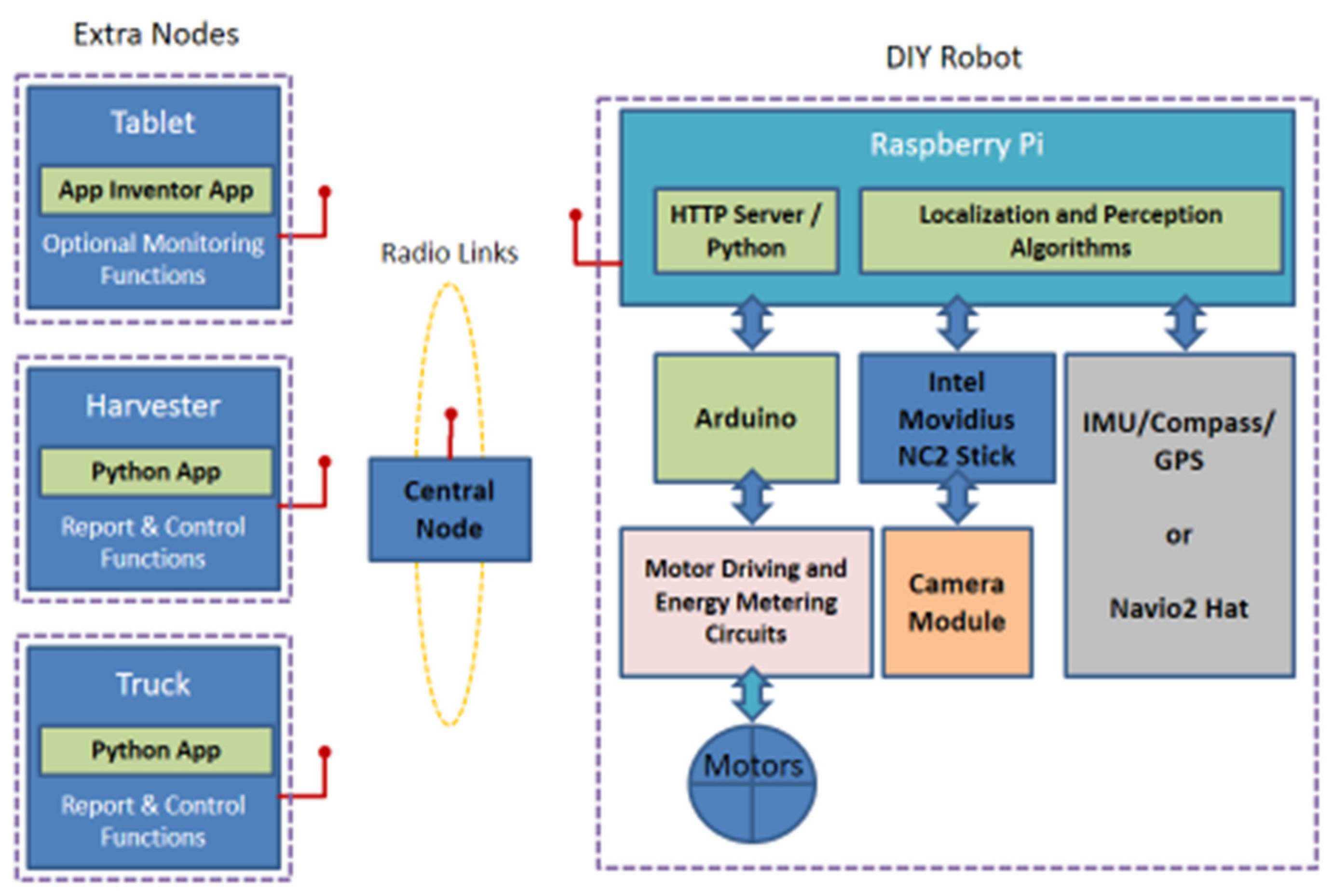
3.7. Interoperability and Networking Issues (Summary of Features)

In recapitulating, the navigation control strategy mainly consists of the following actions, in bullets, while a characteristic diagram highlighting the synergy of features to support the overall functionality of the robotic vehicle is depicted in Figure 7.
  • GPS (and IMU)-assisted continuous robot’s localization, distant target finding (i.e., the tractor or the farmer), and actions for reaching it, according to the lane grid constraints.
  • When close to target, the visual navigation methods, based on machine learning techniques, take control, for a more accurate response.
  • Voice commands functionality facilitates the guidance of the robot by allowing simple instruction execution.
There is provision for real-time information exchanges, reporting harvester’s and truck’s location to the robot, as well as for assistive manual monitoring/overdrive mode through Wi-Fi radios and a smart/phone tablet device. Typically, HTTP, UDP and MQTT messanging mechanisms have been exploited. The hiring of LoRa radio equipment instead of Wi-Fi extends the operational distance to the whole solution to an above-kilometer range. Nevertheless, this protocol should be used for quite sparse traffic, in order not to congest the network, and thus messages have not to be exchanged frequently [60].
A central node can be used to provide networking functionality (i.e., acting as an access point) to location data-keeping services, for the entities participating in the farming activity. The coordination of hardware and software modules hosted on the raspberry pi unit has been addressed via python or Linux shell scripts and common inter-process communication techniques (IPC), like the hiring of UDP sockets in a client–server schema.

4. Evaluation Results and Discussion

Several measurements were performed to assess the behavior of the proposed experimental robotic vehicle. These diverse methods are thoroughly described in Section 4.1, along with the corresponding results. Section 4.2 is dedicated to discussion remarks.

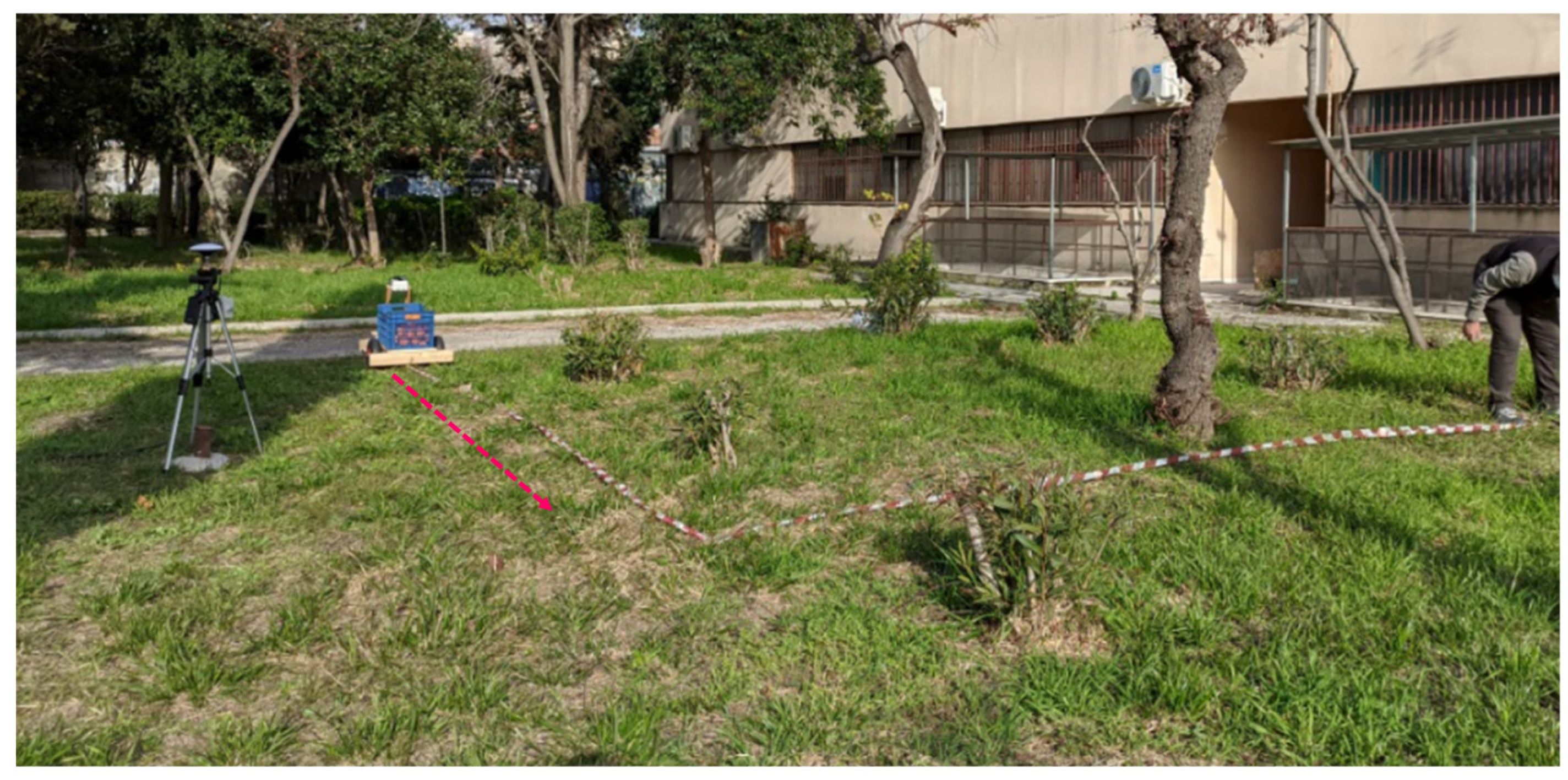
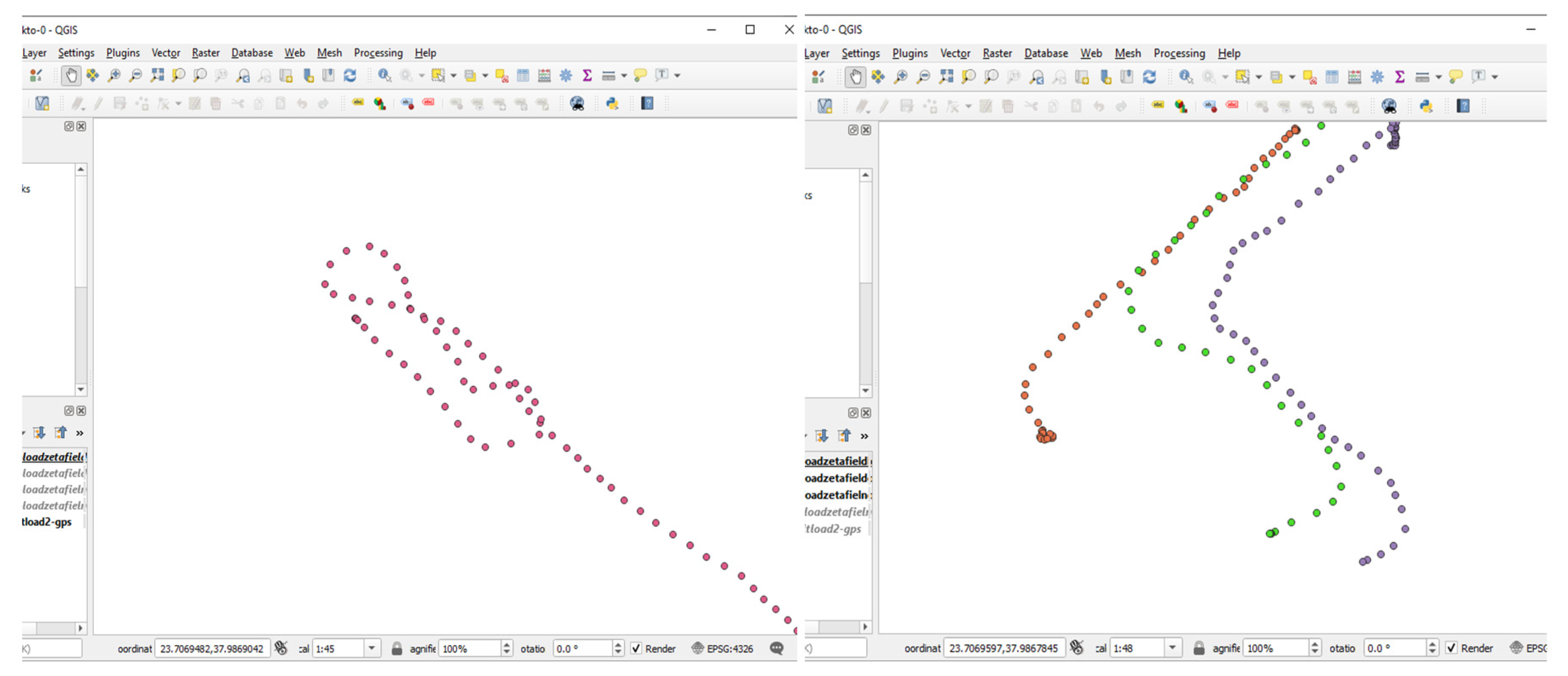
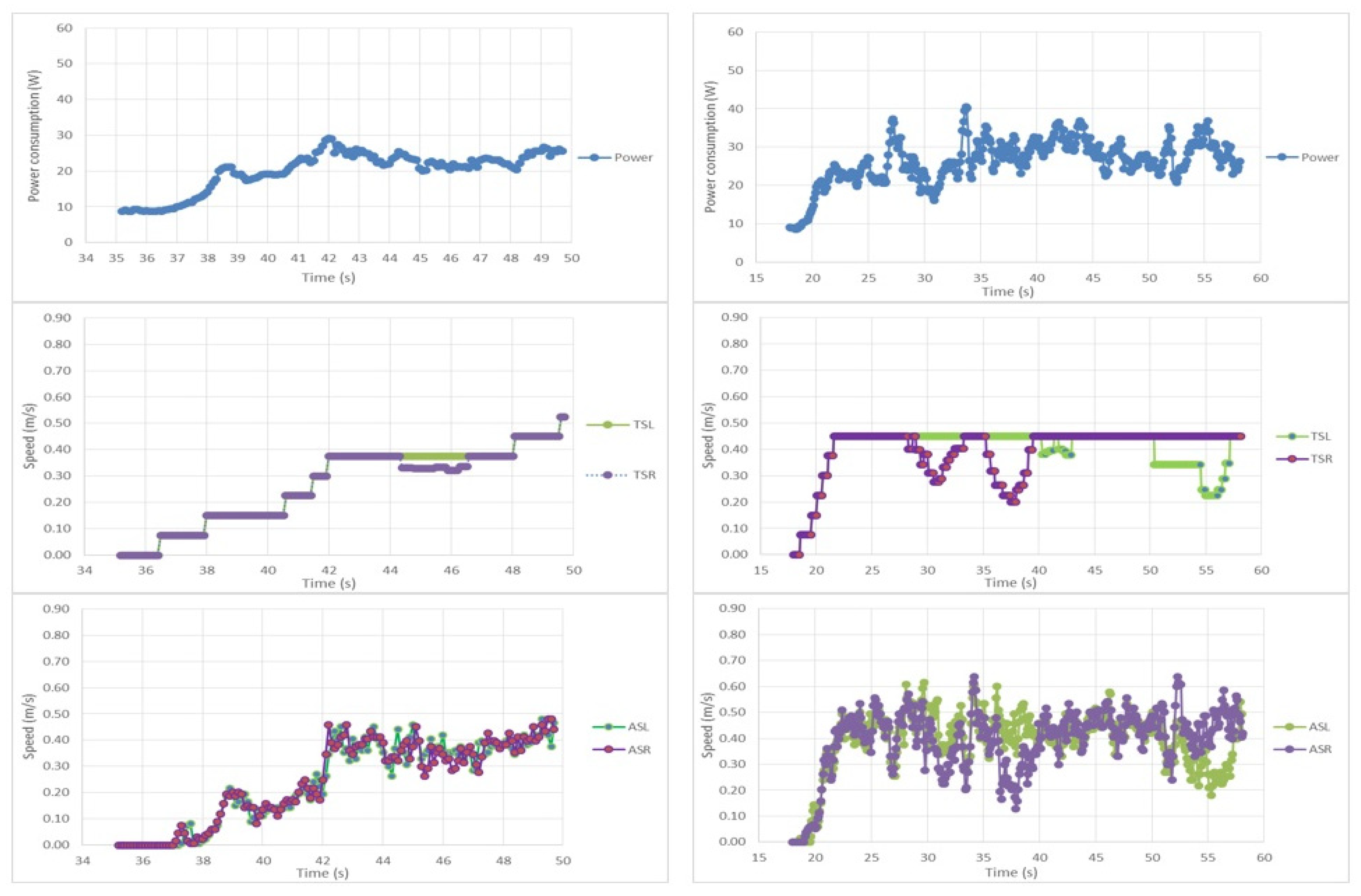
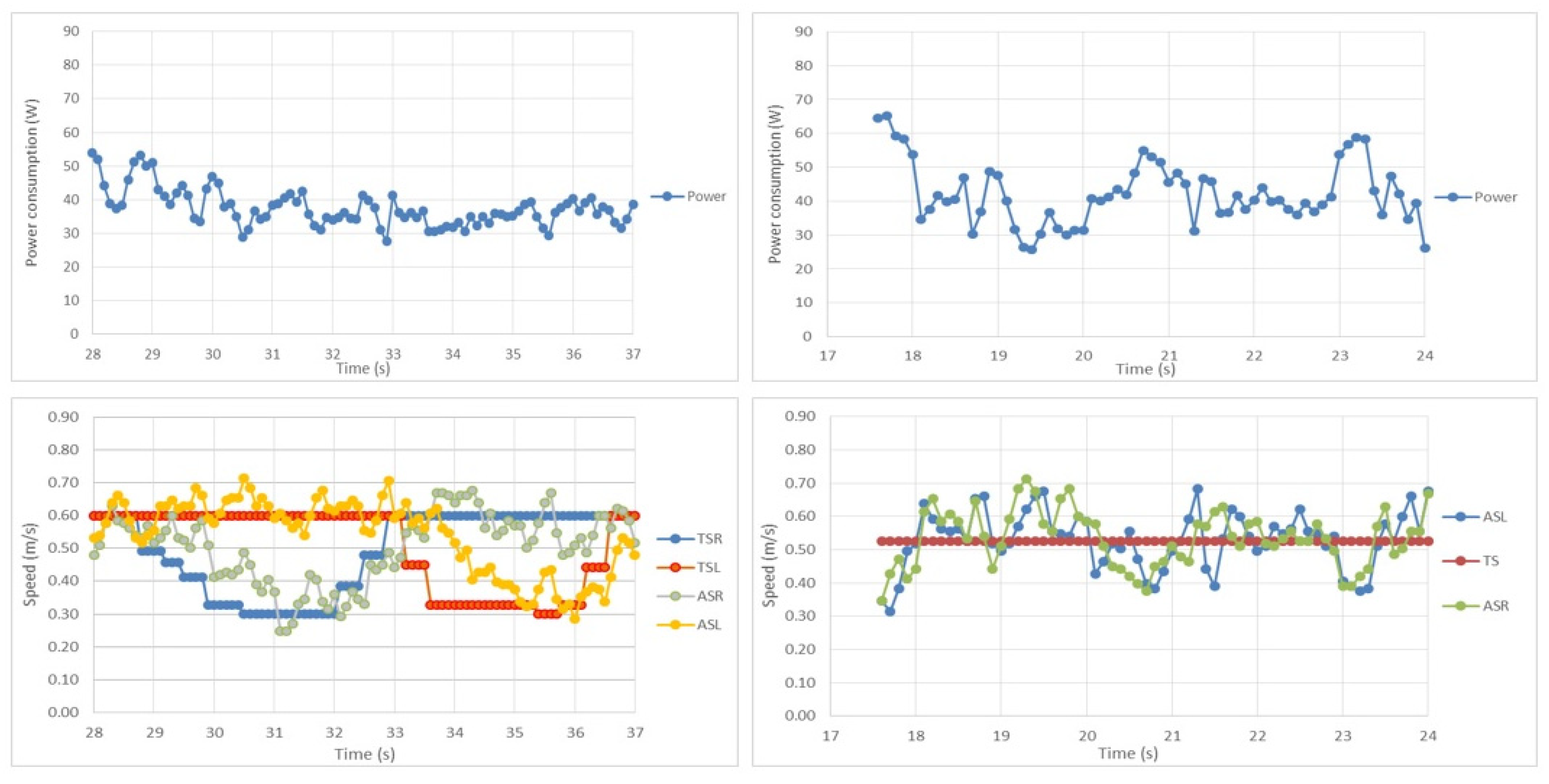
4.1. Testing Details and Results

Referring to the speed of the proposed vehicle, it was close to the one of a slow-walking man, i.e., reaching the 0.75 m/s, which is adequate, as faster speeds would damage the fruit cargo or incurred accidents. This speed magnitude characteristic allows for high-level path correction messages that do not have to be faster than 2–4 times per second, except the low-level control rotational speed updates that it is better to take place every 50 ms (while a 100 ms interval is also adequate). The maximum effective distance range was between 100 m and 150 m, for Wi-Fi equipment and between 800 m and 1200 m, for the LoRa radio equipment. The presence of vegetation and/or other premises had a non-negligible impact on these values. The path accuracy through GPS techniques varied according to the modules being used and the GPS signal reception conditions, and typically, values of the order of ±0.5 m were achieved, assisted by the IMU provided data. The presence of the navio2 raspberry pi hat eased considerably the positioning problem. The hiring of machine vision techniques further improved the situation delivering values of decimeter accuracy range. Indeed, a lot of progress has recently been made for the camera to be able to intercept specific visual patterns (i.e., consecutive plants or the path itself) as simple vectors [40]. The voice commands feature was really helpful and delivered quite satisfactory results, i.e., maintained a success ratio of more than 0.7 under noisy conditions, grace to the ASUS AI noise-canceling USB stick. The total cost of the components used for the construction of the robotic vehicle was 750€, approximately.
The robotic vehicle was tested with cargo weights of up to 15 kg, i.e., near to its net weight. In all cases, it was capable of transporting its cargo on slightly anomalous and inclined terrains. Figure 8 highlights the robotic vehicle in action. The high-level controlling parts, inside the IP55 box, are clearly distinguished as well as the plastic pallet bin carrying testing loads. More specifically in the left part of Figure 8 the cargo, transported on smooth terrain, is comprised of two pots with plants of 10 kg in total, while in the left part the cargo, transported on comparatively rough terrain, is comprised of 15 kg of oranges. The design of the vehicle allows for moving in both directions.
The ability of the robotic vehicle to follow its path on comparatively rough terrains, similar to the ones experienced during the agricultural field operations, was meticulously tested. For this to be done, an accurate RTK GPS system was implemented using suitable u-blox modules, namely the ZED-F9P [61] ones. A base station was fixed at a specific location while the pairing upgraded GPS module was fixed inside the box hosting the high-level control components of the robot. Suitable high-gain multiband antennas were used. The necessary position-correcting data were transmitted from the base station to the robot GPS via a pair of radio telemetry modules. Specific software was implemented so as the high-level controlling unit to record the accurate positioning data into files, at 1sps (samples per second) rate. The whole process was directed by a specific mobile application designed for that purpose using the MIT app inventor software. The final results were fed into the QGIS platform [62] for efficient post-processing and graphical representation. The discussed arrangements, including the robot, the base station, and a suitable testing area are depicted in Figure 9. The corresponding results are shown in Figure 10, for a different path and terrain settings.
More specifically, the left part of Figure 10 corresponds to activity on smooth terrain. The vehicle is driven manually (via a tablet device) so as to move straight and then to perform two turning maneuvers of 0.5 m, in radius. The right part of Figure 10 corresponds to activity on comparatively rough terrain. The red points correspond to manual operation while the green and purple ones were captured while following a man walking on a “Z” path, two meters in front of the robot. For better inspection purposes, part of the “Z” path was covered (in parallel) by leaving a distance of 1m, at the starting and at the ending sides of the “Z”.
All measurements were performed while the vehicle was carrying a 15 kg load. The area shown in both cases is of 10 × 10 m2 approximately. By inspecting the traces in the left and the right part of Figure 10, it can be concluded that the robot moves with slightly fewer deviations on smooth terrains, while in both cases the original path is being followed with satisfactory accuracy.
The left part of Figure 11 depicts the hardware arrangements inside the high-level controlling unit of the robotic vehicle in order to become capable of RTK-level accuracy, i.e., of sub-decimeter level. The key component (i.e., the ZED-F9P unit) is enclosed inside a dashed circle. The involvement of the ZED-F9P units in the proposed platform evaluation process provides a good reason for considering the conditions under which the use of RTK-capable (but comparatively affordable) units would be justified. For instance, if the distance between the consecutive plantation lines is too short (i.e., comparable to the GPS accuracy without GPS), then the presence of a tagging mechanism for each lane is necessary along with a rule that the farmer cannot move from one lane to the next one, without updating his beacon information (e.g., by pressing a button or scanning a barcode tag placed in that lane, using his portable equipment). If this arrangement cannot be implemented easily at specific farm premises, then the hiring of RTK-capable GPS units (i.e., a moderate shift from the 50€ to the 250€ range) is suggested.
In order to efficiently support the energy consumption measuring process, for a considerable amount of amperage (i.e., up to 8 A continuously), in a cost-effective manner, an INA219-based digital metering module provided by Gravity [63] was used. This device exploits differential amplifier/digitizer component in order to provide accurate power measurements, by measuring the voltage drops over a small resistor that the total current feeding the robot passes through, and to deliver these readings to the low-level controlling unit, for further exploitation via an I2C interface. Similarly, the battery voltage of the robot is also reported. The discussed measuring device is placed inside the low-level controlling unit, as depicted in the right part of Figure 11, enclosed by a dashed circle.
The discussed energy-measuring arrangements allow for capturing the short-time dynamics of the vehicle, in real-time. This series of measurements, for diverse load and terrain settings, can be studied in parallel with the corresponding low-level control monitoring data that are recorded simultaneously, in order to better understand and evaluate the robotic vehicle behavior. In this context, an indicative set of characteristic performance results are shown in Figure 12 and Figure 13. More specifically, the top left part of Figure 12 depicts the power consumption (in watts), the target speeds and the actually achieved speeds (in m/s), as a function of time (in seconds), from top to bottom respectively, while the vehicle is accelerating, progressively, on smooth terrain, while loaded. The middle left part of Figure 12 depicts the corresponding target speeds for the right motor (in purple) and the left motor (in green). Both curves are overlapped as the vehicle is moving straight ahead, except for a small period (between second 44 and 46) when the right wheel cuts down the speed to perform a slight correction in direction, slightly to the right. The actual speeds of both side motors (ASL and ASR curves) are trying to follow the target values (TSL and TSR curves), guided by the low-level controlling unit according to PID control rules, as depicted in the bottom-left part of Figure 12. No sudden peaks in the power consumption nor in the speed of the vehicle are experienced. According to the recorded data, the power consumption is around 9 W, at idling, and goes to the 25 W level, at a speed level of 0.50 m/s. Similarly, the three curves in the right part of Figure 12 correspond to the case where the vehicle is moving on comparatively rough terrain at no presence of load. The vehicle accelerates to the target speed level of 45 m/s and performs two consecutive right and left turns, as reflected by the alterations in the right and left side speed respectively. As in the left case (smooth terrain), the actual behavior remains close to the target values while no sudden peaks are experienced. It must be noted that the power consumption is comparable to the one while the vehicle is loaded, but on smooth terrain, while the variability in consumption and actual speeds is now increased. This is due to the fact that on the rough terrain the vehicle has to surpass many small obstacles making the PID controlling mechanism develop a more agile behavior.
For further analysis, the two curves in the left part of Figure 13 correspond to the case where the vehicle is moving on comparatively rough terrain, but now carrying a load and performing a right and a left turn. The top part provides the power consumption data while the bottom part depicts the left and right side target (TSL and TSR curves) and actual speeds (ASL and ASR curves) of the robot. Similarly, in the right part of Figure 13, the short-time dynamics are shown while the vehicle is following a straight line direction and thus both wheels are following the same target speed value (TS curve). In both cases, the power consumption and the actual speed fluctuations are even more intense due to the presence of load and rough terrain, resulting in values close to the 50 W level.
In recapitulating, the vehicle positioning recordings were captured with a rate of 1 sps, while the low-level data with a 10 sps rate. All the corresponding records, stored in the high-level engine memory, had a real-time time stamp, for accurate post-processing purposes. The robot consumed from 9 W to 25 W, on smooth terrains, while the average consumption increased up to 50 W, on rough terrains and loaded. The 6–9 W consumption at idling is justified by the power supply needs of the controlling and communication equipment hosted on the robot. Further experiments on inclined terrains have shown that the total current consumption does not exceed the 60–75 W level. In any case, no extreme peaks were experienced, while the active steering mechanism of the third wheel was ready to absorb any potential remnant of swaying behavior caused by the integral parts of the low-level controlling unit, as it is verified by the positioning traces of the vehicle. The discussed power consumption characteristics allow for a continuous operation duration of about 2 h to 3 h. In order to achieve the maximum theoretical speed of 0.75 m/s for a 30–35 kg mass, 10 J of energy would be enough, but friction, conversion losses and other (i.e., terrain) imperfections make this amount not being adequate. As extracted by the consumption traces, 25 W to 50 W will be necessary for moving the vehicle. Finally, the engagement of an assisting photovoltaic panel of 15 W, as mentioned in Section 3.1, can extend by 25% the autonomous operation duration.

4.2. Discussion

The electromechanical layout and the low-level control functionality of the proposed robotic solution are quite efficient for real-world operations. The proposed vehicle is not intended for use on extreme terrains, but a typical agri-field is not always too rough or too inclined to restrict the usage of vehicles of moderate potential. Furthermore, the proposed vehicle remains small enough to maneuver easily and wide enough, with a low center of gravity, so as not to lose its balance or its cargo. Small cargo positioning adjustment options are also provided, while the robot is capable of bidirectional movement. The active steering capability, combined with the differential drive feature, guarantees good performance in path following, despite small obstacles. The low-level engine controlling the side wheel motors is quite “polite” in its operation as it only tries to follow the left and right target speed suggestions. These suggestions are compliant with the angle command rules for the steering servo, as the controller takes into account the turning radius and speed needs (calculated according to the relevant high-level directions) and the specific vehicle’s geometry characteristics, according to the formulas (1) and (2) explained in Section 3.2. Indeed, the target updates (i.e., mainly radius corrections and possibly requests for different speed) are generated typically at a frequency of 2–4 times per second, while the low-level controlling engine, in its turn, trying to follow these target values, provides 10–20 corrections per second. This faster response rate gives enough freedom to the robot to adjust its driving wheel speed values to the target ones. Every time that the target speed values are recalculated by (2), the third active-steering wheel starts to change its direction, assisted by the servo motor, in order to reach the turning degree calculated by the expression (1). The latter action typically requires 0.25 s to 0.75 s to be completed, time interval long enough for the low-level controlling engine to progressively adjust the discussed wheels’ speeds to the new target values. For this reason, no “straggling” of the side motors is experienced by the active steering system of the third wheel, for a good selection of the controlling algorithm parameters. The high-level speed and radius suggestions, when they are the same as previous, can be suppressed (i.e., not be passed to the low-level control engine), for optimization purposes, i.e., for relieving the inter-process communication mechanism of the robot.
It is also worth mentioning that the non-RTK GPS system could reach accuracies even better (i.e., lower) than 0.5 m, on clear sky view conditions, while the RTK-capable system could worsen its sub-decimeter accuracy under no clear sky view conditions. The difference in GPS performance, according to the absence or presence of the RTK functionality (e.g., by disconnecting the data correction signals between the base station and the robot), was meticulously studied using the u-center evaluation software [64], which provides detailed information, like real-time deviation maps, for any u-blox chip-assisted GPS receiver device, like the ones being used herein. The fact that the performance of the RTK GPS system may sometimes worsen indicates the necessity of assistance by complementary techniques and systems, like the vision-based navigation and the IMU data units. For this reason, the high-level control functionality is better to be based on a synergy of features, provided by a balanced collection of innovative and cost-effective components with complementary characteristics.
Apparently, more work has yet to be done with the high-level algorithms and methods, in order to achieve an absolutely seamless behavior. The whole approach does not profess to deliver a complete “turn-key” solution but rather to highlight the fact that the necessary technologies are becoming more and more available, affordable and mature to allow the construction of promising machines, at very appealing cost and performance levels that were not possible a few years ago. The electromechanical design being followed is simple but robust, supporting fundamental automatic control functionality. In-line with the DIY philosophy, instead of paying for expensive and “closed”, large-scale solutions, quite inexperienced groups (either students or farmers), by using simple materials and instructions, can create machines that can work under real agri-field conditions. Indeed, the innovative components being used, like the ones described in [34,35,36,37,38,39,40,41,42,43,61,63], are quite easy-to-find and well-supported, in order to be combined together, reused and easily repaired/upgraded. In parallel, the whole design is intentionally kept very modular in order to provide freedom for future enhancements and diverse testing scenarios. The robotic vehicle being described comprises a good example of a cost-effective “vanilla” platform that, apart from its practical usage in the agri-fields, allows for many experiments involving enhanced sensor data fusion techniques and intelligent decision-making engines. Finally, this vehicle can be viewed as a living example of an educationally fruitful environment assisting students getting involved in its construction to demystify several high-end technologies that are to be used in the modern agricultural production reality, in a far more realistic scale than the one being presented in previous works [25,26].

5. Conclusions and Future Work

The work presented reports on the efforts to design and implement a small autonomous electric vehicle able to carry fruits/vegetables from the harvester’s location to the truck’s location to reduce the labor hands required. Benefiting from the recent technological advances and cost reduction in the electronic components market, the proposed solution combines quite inexpensive sensing elements with hardware accelerator components for machine vision and speech recognition, in order to better exploit an underlying platform exhibiting fundamental automatic control functionality and stable operation. Manual overdrive for monitoring purposes and emergency cases is also provided. The remote communication is addressed using Wi-Fi interfaces, while experimentation with LoRa interfaces, for better distance range coverage, was also tested. The vehicle is fully electric using batteries, while solar panel assistance solutions were also taken under consideration. For fluent evaluation purposes, the vehicle is equipped with additional components so as to provide detailed real-time recordings of its critical operating parameters, its position and its power consumption. The whole approach tries to combine cost-effectiveness with efficient operation and, in parallel, to maintain simplicity and modularity so as to be comprehensive, maintainable and exploitable by quite inexperienced users, like farmers or students, acting as a fruitful example for their university lesson curriculum.
Plans for the future include the study and the fusion of more sophisticated sensing and processing units and methods, like advanced machine learning techniques. Deeper experimentation with robotic vehicles of this class, studying their accuracy, autonomy and power consumption is also important. Beyond that, the investigation of further small-scale robotic variants for assisting farmers in their activities is an apparent priority. Finally, the application and study of various human-to-machine or machine-to-machine collaboration techniques, like swarm management, for increasing productivity and safety and reducing operating costs, is also a significant future direction.

Author Contributions

D.L. conceived the idea for the paper, designed most of the platform, was responsible for the implementation and validation process and wrote several parts. E.P. mainly assisted D.L. in the machine vision part deployment. K.M. mainly contributed by addressing several localization modelling issues. I.-V.K. and V.D. assisted D.L. in the electromechanical deployment of the robot and in the testing stage. Finally, K.G.A. helped by providing valuable advice and addressed several administration tasks. All authors have read and agreed to the published version of the manuscript.

Funding

This research received no external funding.

Institutional Review Board Statement

Not applicable.

Informed Consent Statement

Not applicable.

Data Availability Statement

The data presented in this study are available on request from the corresponding author.

Acknowledgments

The authors would like to thank the students of the Dept. of Natural Resources Management & Agricultural Engineering of the Agricultural University of Athens, Greece, for their assistance in the deployment and testing of the discussed platform.

Conflicts of Interest

The authors declare no conflict of interest.

References

  1. United Nations. UN Report on Earth’s Population. 2020. Available online: https://www.un.org/en/sections/issues-depth/population/index.html (accessed on 30 October 2020).
  2. FAO. The Future of Food and Agriculture—Trends and Challenges. 2018. Available online: http://www.fao.org/3/a-i6583e.pdf (accessed on 30 October 2020).
  3. O’Grady, M.J.; O’Hare, G.M. Modelling the smart farm. Inf. Process. Agric. 2017, 4, 179–187. [Google Scholar] [CrossRef]
  4. Bechar, A.; Vigneault, C. Agricultural robots for field operations: Concepts and components. Biosyst. Eng. 2016, 149, 94–111. [Google Scholar] [CrossRef]
  5. Bechar, A.; Vigneault, C. Agricultural robots for field operations. Part 2: Operations and systems. Biosyst. Eng. 2017, 153, 110–128. [Google Scholar] [CrossRef]
  6. Krishna, K.R. Push Button Agriculture: Robotics, Drones, Satellite-Guided Soil and Crop Management; Apple Academic Press: Oakville, ON, Canada, 2016; ISBN 13: 978-1-77188-305-4. (eBook-PDF). [Google Scholar]
  7. UK-RAS Network: Robotics & Autonomous Systems. Agricultural Robotics: The Future of Robotic Agriculture, UK-RAS White Papers; UK-RAS Network: London, UK, 2018; Available online: https://arxiv.org/ftp/arxiv/papers/1806/1806.06762.pdf (accessed on 20 August 2020).
  8. Roldan, J.J.; del Cerro, J.; Garzon-Ramos, D.; Garcia-Aunon, P.; Garzon, M.; de Leon, J.; Barrientos, A. Robots in agriculture: State of art and practical experiences. In Service Robots; IntechOpen: London, UK, 2017. [Google Scholar]
  9. Shockley, J.M.; Dillon, C.R. An Economic Feasibility Assessment for Adoption of Autonomous Field Machinery in Row Crop Production. In Proceedings of the 2018 International Conference on Precision Agriculture, Montreal, QC, Canada, 24–27 June 2018. [Google Scholar]
  10. Fountas, S.; Mylonas, N.; Malounas, I.; Rodias, E.; Santos, C.H.; Pekkeriet, E. Agricultural Robotics for Field Operations. Sensors 2020, 20, 2672. [Google Scholar] [CrossRef]
  11. Lamborelle, A.; Álvarez, L.F. Farming 4.0: The Future of Agriculture? Available online: https://www.euractiv.com/section/agriculture-food/infographic/farming-4-0-the-future-of-agriculture/ (accessed on 20 October 2020).
  12. King, A. Technology: The Future of Agriculture. Nat. Cell Biol. 2017, 544, S21–S23. [Google Scholar] [CrossRef] [Green Version]
  13. Shamshiri, R.R.; Weltzien, C.; Hameed, I.A.; Yule, I.J.; Grift, T.E.; Balasundram, S.K.; Pitonakova, L.; Ahmad, D.; Chowdhary, G. Research and development in agricultural robotics: A perspective of digital farming. Int. J. Agric. Biol. Eng. 2018, 11, 1–11. [Google Scholar] [CrossRef]
  14. Gaus, C.-C.; Urso, L.M.; Minßen, T.F.; de Witte, T. Economics of mechanical weeding by a swarm of small field robots. In Proceedings of the 57th Annual Conference of German Association of Agricultural Economists (GEWISOLA), Weihenstephan, Germany, 13–15 September 2017. [Google Scholar]
  15. Sørensen, C.; Bochtis, D. Conceptual model of fleet management in agriculture. Biosyst. Eng. 2010, 105, 41–50. [Google Scholar] [CrossRef]
  16. Fountas, S.; Gemtos, T.A.; Blackmore, S. Robotics and Sustainability in Soil Engineering. In Soil Engineering; Springer: Berlin, Germany, 2010; pp. 69–80. [Google Scholar]
  17. Martinez-Martin, E.; Escalona, F.; Cazorla, M. Socially Assistive Robots for Older Adults and People with Autism: An Overview. Electronics 2020, 9, 367. [Google Scholar] [CrossRef] [Green Version]
  18. World Health Organization (WHO). Disability. 2019. Available online: https://www.who.int/disabilities/en/ (accessed on 20 August 2020).
  19. Harrop, P.; Dent, M. Electric Vehicles and Robotics in Agriculture 2020–2030, IDTechEx. Available online: https://www.idtechex.com/en/research-report/electric-vehicles-and-robotics-in-agriculture-2020-2030/717 (accessed on 20 February 2021).
  20. International Federation of Robotics (IFR). IFR Press Releases 2020. Available online: https://ifr.org/downloads/press2018/Presentation_Service_Robots_2020_Report.pdf (accessed on 20 February 2021).
  21. Aymerich-Franch, L.; Ferrer, I. The implementation of social robots during the COVID-19 pandemic. arXiv 2020, arXiv:2007.03941. [Google Scholar]
  22. Thomasson, J.A.; Baillie, C.P.; Antille, D.L.; Lobsey, C.R.; McCarthy, C.L. Autonomous technologies in agricultural equipment: A review of the state of the art. In Proceedings of the 2019 Agricultural Equipment Technology Conference, Louisville, KY, USA, 11 February 2019; American Society of Agricultural and Biological Engineers: St. Joseph, MI, USA, 2019. [Google Scholar] [CrossRef]
  23. Fayyad, J.; Jaradat, M.A.; Gruyer, D.; Najjaran, H. Deep Learning Sensor Fusion for Autonomous Vehicle Perception and Localization: A Review. Sensors 2020, 20, 4220. [Google Scholar] [CrossRef]
  24. Doran, M.V.; Clark, G.W. Enhancing Robotic Experiences throughout the Computing Curriculum. In Proceedings of the 49th ACM Technical Symposium on Computer Science Education (SIGCSE’18), Baltimore, MD, USA, 21–24 February 2018; pp. 368–371. [Google Scholar]
  25. Loukatos, D.; Tzaninis, G.; Arvanitis, K.G.; Armonis, N. Investigating Ways to Develop and Control a Multi Purpose and Low Cost Agricultural Robotic Vehicle, under Scale. In Proceedings of the XXXVIII CIOSTA & CIGR V International Conference (CIOSTA2019), Rhodes, Greece, 24–26 June 2019. [Google Scholar]
  26. Loukatos, D.; Arvanitis, K.G. Extending Smart Phone Based Techniques to Provide AI Flavored Interaction with DIY Robots, over Wi-Fi and LoRa interfaces. Educ. Sci. 2019, 9, 224. [Google Scholar] [CrossRef] [Green Version]
  27. Zhang, G.; Li, G.; Peng, J. Risk Assessment and Monitoring of Green Logistics for Fresh Produce Based on a Support Vector Machine. Sustainability 2020, 12, 7569. [Google Scholar] [CrossRef]
  28. Ngo, H.Q.T.; Phan, M.-H. Design of an Open Platform for Multi-Disciplinary Approach in Project-Based Learning of an EPICS Class. Electronics 2019, 8, 200. [Google Scholar] [CrossRef] [Green Version]
  29. Quaglia, G.; Visconte, C.; Scimmi, L.S.; Melchiorre, M.; Cavallone, P.; Pastorelli, S. Design of a UGV Powered by Solar Energy for Precision Agriculture. Robotics 2020, 9, 13. [Google Scholar] [CrossRef] [Green Version]
  30. Rbr. The Ultimate Guide to Agricultural Robotics. 2017. Available online: https://www.roboticsbusinessreview.com/agriculture/the_ultimate_guide_to_agricultural_robotics/ (accessed on 30 April 2020).
  31. Grimstad, L.; From, P.J. The Thorvald II agricultural robotic system. Robotics 2017, 6, 24. [Google Scholar] [CrossRef] [Green Version]
  32. Saga Robotics. The Official Site of Saga Robotics. 2021. Available online: https://sagarobotics.com/ (accessed on 20 February 2021).
  33. AFN. Description of the Recent Financial Raise of Saga Robotics. 2021. Available online: https://agfundernews.com/saga-robotics-raises-11m-to-develop-robo-strawberry-pickers.html (accessed on 31 March 2021).
  34. Arduino Uno. Arduino Uno Board Description on the Official Arduino Site. 2020. Available online: https://store.arduino.cc/arduino-uno-re (accessed on 15 September 2020).
  35. Raspberry. Raspberry Pi 3 Model B Board Description on the Official Raspberry Site. 2020. Available online: https://www.raspberrypi.org/products/raspberry-pi-3-model-b/ (accessed on 20 September 2020).
  36. WeMos. The WeMos D1 R2 Board. 2020. Available online: https://wiki.wemos.cc/products:d1:d1 (accessed on 20 August 2020).
  37. LSM9DS1. Description of the SparkFun 9DoF IMU Breakout-LSM9DS1. 2020. Available online: https://www.sparkfun.com/products/13284 (accessed on 20 September 2020).
  38. U-blox M9. The U-Blox M9 Products Generation. 2021. Available online: https://www.u-blox.com/en/robust-nature (accessed on 22 February 2021).
  39. Navio2. “Navio2: Autopilot HAT for Raspberry Pi”, Official Description of the Emlid Navio2 Board. 2020. Available online: https://emlid.com/navio/ (accessed on 20 August 2020).
  40. Pixy2. Description of the Pixy2 AI-Assisted Robot Vision Camera. 2020. Available online: https://pixycam.com/pixy2/ (accessed on 20 September 2020).
  41. OpenCV. Description of the OpenCV, an Open Source Computer Vision and Machine Learning Software. 2020. Available online: https://opencv.org/about/ (accessed on 20 September 2020).
  42. Movidius Stick (2020) Intel® Movidius™ Neural Compute Stick. Available online: https://ark.intel.com/content/www/us/en/ark/products/125743/intel-movidius-neural-compute-stick.html (accessed on 30 September 2020).
  43. ASUS. ASUS AI Noise-Canceling Mic Adapter with USB-C 3.5 mm Connection. 2020. Available online: https://www.asus.com/Accessories/Streaming-Kit/All-series/AI-Noise-Canceling-Mic-Adapter/ (accessed on 30 September 2020).
  44. PyGeodesy. The PyGeodesy Python Library Implementation and Description. 2020. Available online: https://github.com/mrJean1/PyGeodesy (accessed on 25 September 2020).
  45. Hruska, J. New Movidius Myriad X VPU Packs a Custom Neural Compute Engine. 2017. Available online: https://www.extremetech.com/computing/254772-new-movidius-myriad-x-vpu-packs-custom-neural-compute-engine (accessed on 25 September 2020).
  46. Kyriakos, A.; Papatheofanous, E.A.; Bezaitis, C.; Petrongonas, E.; Soudris, D.; Reisis, D. Design and Performance Comparison of CNN Accelerators Based on the Intel Movidius Myriad2 SoC and FPGA Embedded Prototype. In Proceedings of the 2019 International Conference on Control, Artificial Intelligence, Robotics & Optimization (ICCAIRO), Athens, Greece, 8–9 December 2019; IEEE: Los Alamitos, CA, USA, 2019; pp. 142–147. [Google Scholar] [CrossRef]
  47. Lentaris, G.; Maragos, K.; Stratakos, I.; Papadopoulos, L.; Papanikolaou, O.; Soudris, D.; Lourakis, M.; Zabulis, X.; Gonzalez-Arjona, D.; Furano, G. High-Performance Embedded Computing in Space: Evaluation of Platforms for Vision-Based Navigation. J. Aerosp. Inf. Syst. 2018, 15, 178–192. [Google Scholar] [CrossRef]
  48. Lentaris, G.; Stamoulias, I.; Soudris, D.; Lourakis, M. HW/SW Codesign and FPGA Acceleration of Visual Odometry Algorithms for Rover Navigation on Mars. IEEE Trans. Circuits Syst. Video Technol. 2016, 26, 1563–1577. [Google Scholar] [CrossRef]
  49. Ran, L.; Zhang, Y.; Zhang, Q.; Yang, T. Convolutional neural network-based robot navigation using uncalibrated spherical images. Sensors 2017, 17, 1341. [Google Scholar] [CrossRef] [PubMed]
  50. Lin, T.Y.; Maire, M.; Belongie, S.; Hays, J.; Perona, P.; Ramanan, D.; Dollár, P.; Zitnick, C.L. Microsoft coco: Common objects in context. In European Conference on Computer Vision; Springer: Cham, Switzerland, 2014; pp. 740–755. [Google Scholar]
  51. Wang, R.J.; Li, X.; Ling, C.X. Pelee: A real-time object detection system on mobile devices. In Advances in Neural Information Processing Systems 31: 32nd Conference on Neural Information Processing Systems (NeurIPS 2018); Curran Associates, Inc.: New York, NY, USA, 2019; pp. 1963–1972. [Google Scholar]
  52. Bradski, G.; Kaehler, A. Learning OpenCV: Computer Vision with the OpenCV Library; O’Reilly Media, Inc.: Sebastopol, CA, USA, 2008. [Google Scholar]
  53. Loukatos, D.; Arvanitis, K.G.; Armonis, N. Investigating Educationally Fruitful Speech-Based Methods to Assist People with Special Needs to Care Potted Plants. In Human Interaction and Emerging Technologies. IHIET 2019. Advances in Intelligent Systems and Computing; Springer: Cham, Switzerland, 2018; Volume 1018. [Google Scholar] [CrossRef]
  54. Loukatos, D.; Kahn, K.; Alimisis, D. Flexible Techniques for Fast Developing and Remotely Controlling DIY Robots, with AI Flavor. In Educational Robotics in the Context of the Maker Movement. Edurobotics 2018. Advances in Intelligent Systems and Computing; Moro, M., Alimisis, D., Iocchi, L., Eds.; Springer: Cham, Switzerland, 2020; Volume 946. [Google Scholar] [CrossRef]
  55. Loukatos, D.; Fragkos, A.; Arvanitis, K.G. Exploiting Voice Recognition Techniques to Provide Farm and Greenhouse Monitoring for Elderly or Disabled Farmers, over WI-FI and LoRa Interfaces. In Bio-Economy and Agri-Production: Concepts and Evidence; Bochtis, D., Achillas, C., Banias, G., Lampridi, M., Eds.; Academic Press: London, UK, 2021. [Google Scholar] [CrossRef]
  56. SOPARE. Sound Pattern Recognition—SOPARE. 2020. Available online: https://www.bishoph.org/ (accessed on 30 October 2020).
  57. MQTT. The MQ Telemetry Transport Protocol (Wikipedia). 2020. Available online: https://en.wikipedia.org/wiki/MQTT (accessed on 20 October 2020).
  58. Draguno. The LoRa Draguno Shield for Arduino. 2020. Available online: http://www.dragino.com/products/module/item/102-lora-shield.html (accessed on 20 October 2020).
  59. LoRa. LoRa Protocol Description on Wikipedia. 2020. Available online: https://en.wikipedia.org/wiki/LoRa (accessed on 15 October 2020).
  60. Sanchez-Iborra, R.; Sanchez-Gomez, J.; Ballesta-Viñas, J.; Cano, M.-D.; Skarmeta, A.F. Performance Evaluation of LoRa Considering Scenario Conditions. Sensors 2018, 18, 772. [Google Scholar] [CrossRef] [PubMed] [Green Version]
  61. ZED-F9P. The SparkFun ZED-F9P GPS-RTK2 Board Description. 2021. Available online: https://www.sparkfun.com/products/15136 (accessed on 22 February 2021).
  62. QGIS. The QGIS Geographic Information System Application Software, Release 3.10. 2021. Available online: https://blog.qgis.org/2019/11/02/qgis-3-10-a-coruna-is-released/ (accessed on 22 February 2021).
  63. Gravity. The Gravity I2C Digital Wattmeter Module Using the INA219 Chip. 2020. Available online: https://www.dfrobot.com/product-1827.html (accessed on 22 February 2021).
  64. U-Center. The U-Center Evaluation Software Description. 2021. Available online: https://www.u-blox.com/en/product/u-center (accessed on 31 March 2021).
Figure 1. A typical arrangement for all the components being necessary for the fruit transport process.
Machines 09 00082 g001
Figure 2. The basic electromechanical layout of the harvester-assisting vehicle: (a) Initial design; (b) Implementation outcome.
Machines 09 00082 g002
Figure 3. The geometry of the vehicle implies a specific set of calculations in order to feed the low-level control components with the necessary information for turning at a given radius, speed.
Machines 09 00082 g003
Figure 4. (a) The plan of a field consisting of five parallel plantation lines; (b) The grid modeling this field, containing 6 lanes, 2 sides and 12 waypoints. The vehicle is allowed to move only on lanes and sides, and any path between two points reduces to a sequence of intermediate waypoints.
Machines 09 00082 g004
Figure 5. A typical high-level control components arrangement inside an IP55 plastic box, including a navio2 unit, a raspberry pi model 3B, an Intel NCS-2 module, and a USB camera. The connection with indicative low-level components (here, an arduino uno unit, on the left) is also shown.
Machines 09 00082 g005
Figure 6. An indicative arrangement allowing for voice command functionality and GPS positioning using a raspberry pi 3 model A+, a LoRa Dragino radio module, and the ASUS AI noise-canceling stick plus a headset. This system variant is tailored for accompanying the operator (i.e., the farmer).
Machines 09 00082 g006
Figure 7. A typical interoperability diagram highlighting the roles of the entities used to support the autonomous vehicle’s functionality.
Machines 09 00082 g007
Figure 8. The robotic vehicle in action: the high-level controlling parts, inside the IP55 box, are clearly distinguished as well as the plastic pallet bin carrying testing cargos of 10–15 kg, approximately, on smooth (at the left) and comparatively rough (at the right) terrains.
Machines 09 00082 g008
Figure 9. The experimental arrangement deployment being necessary for testing the path-following accuracy of the proposed robotic vehicle on both smooth and comparatively rough terrains.
Machines 09 00082 g009
Figure 10. The activity traces of the robotic vehicle for smooth (in the left part) and rough (in the right part) terrains, as visualized using the QGIS software package.
Machines 09 00082 g010
Figure 11. The hardware arrangements of the robotic vehicle providing RTK-level accuracy (in the left) and efficient energy measurement (in the right). The key components (i.e., the RTK GPS and the INA219 power meter) are enclosed inside dashed circles.
Machines 09 00082 g011
Figure 12. Detailed recordings of the dynamic behavior of the robotic vehicle, from the low-level control unit perspective in two cases: on smooth terrains while loaded (left part) and on comparatively rough terrains while unloaded (right part).
Machines 09 00082 g012
Figure 13. Detailed recordings of the dynamic behavior of the robotic vehicle, from the low-level control unit perspective, on comparatively rough terrains and loaded in two cases: turning (left part) and moving straight (right part).
Machines 09 00082 g013
Table 1. The calculated velocity and angle values, in order for the vehicle to turn fluently, for a given initial velocity and turning radius.
riviθ
0.010.0257.0
0.100.1748.8
0.500.5028.1
1.000.6717.7
2.000.8010.1
4.000.895.4
8.000.942.8
10.000.952.2
15.000.971.5
Publisher’s Note: MDPI stays neutral with regard to jurisdictional claims in published maps and institutional affiliations.

