Article

Segmented Embedded Rapid Defect Detection Method for Bearing Surface Defects

1
Shanghai Institute of Technical Physics, Chinese Academy of Sciences, Shanghai 200083, China
2
School of Electronic, Electrical and Communication Engineering, University of Chinese Academy of Sciences, Beijing 100049, China
3
School of Information Science and Technology, ShanghaiTech University, Shanghai 201210, China
4
Key Laboratory of Intelligent Infrared Perception, Chinese Academy of Sciences, Shanghai 200083, China
*
Author to whom correspondence should be addressed.
Current address: Shanghai Institute of Technical Physics, Chinese Academy of Sciences, Shanghai 200083, China.
Machines 2021, 9(2), 40; https://doi.org/10.3390/machines9020040
Submission received: 25 December 2020 / Revised: 9 February 2021 / Accepted: 10 February 2021 / Published: 14 February 2021
(This article belongs to the Section Machines Testing and Maintenance)

Abstract

:
The rapid development of machine vision has prompted the continuous emergence of new detection systems and algorithms in surface defect detection. However, most of the existing methods establish their systems with few comparisons and verifications, and the methods described still have various problems. Thus, an original defect detection method: Segmented Embedded Rapid Defect Detection Method for Surface Defects (SERDD) is proposed in this paper. This method realizes the two-way fusion of image processing and defect detection, which can efficiently and accurately detect surface defects such as depression, scratches, notches, oil, shallow characters, abnormal dimensions, etc. Besides, the character recognition method based on Spatial Pyramid Character Proportion Matching (SPCPM) is used to identify the engraved characters on the bearing dust cover. Moreover, the problem of characters being cut in coordinate transformation is solved through Image Self-Stitching-and-Cropping (ISSC). This paper adopts adequate real image data to verify and compare the methods and proves the effectiveness and advancement through detection accuracy, missing alarm rate, and false alarm rate. This method can provide machine vision technical support for bearing surface defect detection in its real sense.

1. Introduction

Bearings are important mechanical parts produced in large quantities by assembly lines. In the process of bearing production and assembly, due to the impact of some factors such as equipment wear, collision, and extrusion, oil pollution, bearings inevitably show some abnormal shapes, colors, or dimensions, which are so-called bearing defects. The bearing defects can cause different degrees of quality problems in the machine, leading to failures or serious damage to the machine. Therefore, bearing surface defect detection [1] and bearing fault diagnosis [2,3,4] are of great significance.
Bearing fault diagnosis generally analyzes the signals in bearings to identify the damage or fault in the bearings. Peng [5] uses an improved Hilbert–Huang transform (HHT), which is a time-frequency method to detect the bearing faults. Randall [6] analyzes the impulsive signals from bearing faults by spectral correlation and envelope analysis. Lou [7] designs a scheme for bearing fault diagnosis based on processing the vibration signals by the wavelet transform and neuro-fuzzy classification. Moreover, with the development of artificial intelligent, some deep learning based methods [8,9,10] analyze time/frequency-domain vibration signals, extract features from them, and the neural networks can be sufficient to identify the faults of bearings. Besides, some state-of-the-art damage identification methods [11,12,13] have excellent identification capability and can be used to diagnose the bearing faults.
Bearing surface defect detection methods can be roughly divided into two categories: one is the methods based on image processing and detection algorithms [14,15,16], and the other is the methods based on machine learning (deep learning) [17,18,19]. However, the two methods are not mutually contradictory. For instance, Liu [20] uses methods of image processing and detection to filter, locate, segment, and detect bearing images but uses the neural network method for reasoning on the character recognition on the bearing dust cover. Shen [21] also adopts image processing methods for filtering, segmentation, dimension detection, and character recognition of bearing images. However, in the process of defect detection, he detects defects through SVM training the Blob feature of bearing images. Chen [22] uses the traditional subtraction method and template matching to detect defects and characters, respectively. Deng [23] detects defects through shape features: the edge detection detects the defect boundary, the chain code indicates the defect boundary, and the tightness information is used to extract the defects.
This article focuses on bearing surface defect detection. The existing methods of bearing surface defect detection have some typical common problems. Firstly, they have repetitive steps and high redundancy. Secondly, the modules of the system are too independent, lacking integration and essential connections. These not only increase the complexity of the algorithms but also reduce the accuracy of defect detection. This paper has proposed some innovative methods that have solved the problems mentioned above and improved performances. We adopt a simple but effective method: Image Self-Stitching-and-Cropping (ISSC) to maintain the character integrity. The character recognition method based on Spatial Pyramid Character Proportion Matching (SPCPM) is used to identify the engraved characters on the bearing dust cover. Moreover, we realized the two-way fusion of image processing and defect detection through the Segmented Embedded Rapid Defect Detection Method for Surface Defects (SERDD). These methods make the entire bearing surface defect detection system simpler and more practical, significantly improve the detection accuracy, and decrease missing alarm rate and false alarm rate compared to peers.

2. Methods

In the existing surface defect detection methods, defect detection is an important module after image processing [24,25,26]. This paper changes this mode and adopts an innovative two-way fusion method of image processing and defect detection. Defect detection is no longer an independent step in the whole system, but some integrated and synchronized parts in image processing. Some defect detection processes are even the image processing itself. We call this defect detection method as Segmented Embedded Rapid Defect Detection Method for Surface Defects (SERDD). Because it is integrated and synchronized with image processing, SERDD can streamline the system’s execution steps and reduce algorithm complexity and time overhead.
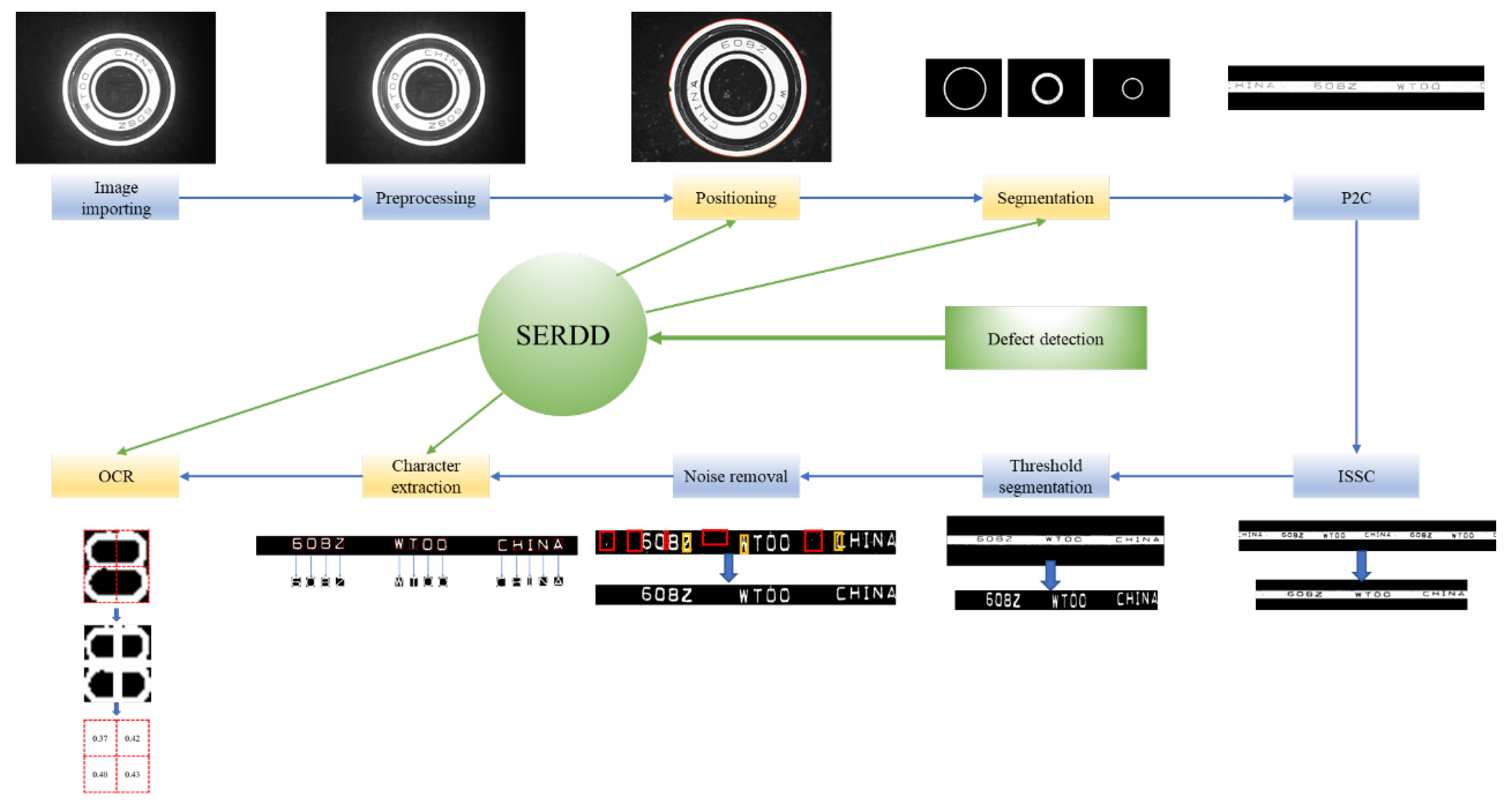
The core idea of SERDD is to embed defect detection into image processing through particular characteristics of image processing, to form a segmented detection mode. Notch, abnormal dimension, non-character region defects, and character defects are detected in four image processing stages of bearing positioning, bearing segmentation, character extraction, and character recognition, respectively, as shown in Figure 1. The principle and implementation processes are described in the following section.

3. Algorithm Steps

3.1. Algorithm Flow

The algorithm of SERDD is combined with two parts: image processing and defect detection. The specific algorithm flow is shown in Figure 2. It can be seen from Figure 2 that image processing proceeds in sequence from image reading to character recognition. SERDD embeds the defect detection into image processing modules in the yellow boxes. Therefore, in addition to completing image processing tasks, these modules also have the ability of simultaneous defect detection. These will be described in detail in the following sections.

3.2. Image Preprocessing

The bearing surface image obtained by the image acquisition system is shown in Figure 3.
Bilateral filtering and median filtering are successively used on the image, eliminating most of the noise on the bearing surface and background.

3.3. Bearing Positioning and Notch Detection

3.3.1. Bearing Positioning

Since the big difference between bearing and background, we can easily find the bearing’s outer contour. According to the contour, the center of the bearing and radius can be calculated by the least square method. The outer circle can be deduced reversely from the center of the bearing and radius.

3.3.2. Notch Detection of Bearing Outer Ring

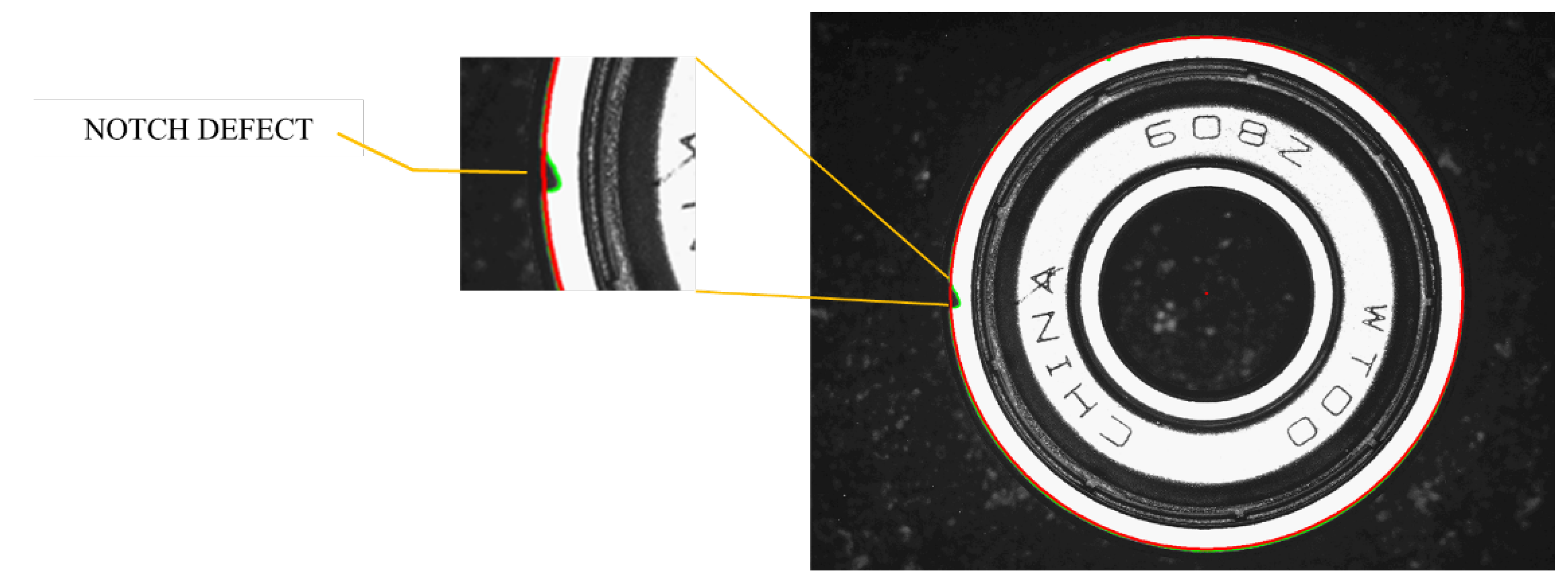
By calculating the Euclidean distance between the contour of the outer ring and the circle derived by the least square method, it can be determined whether there is a notch on the bearing’s outer circle. Namely, if the Euclidean distance is greater than the reference threshold, some notches are on the outer contour.
Assuming that the point set on the contour of the outer circle is Con = { x 1 , x 2 , , x n } , and x i is a point somewhere on the contour, and assuming that the point set on the circle derived from the center of the circle and radius is Cir = { y 1 , y 2 , , y n } , and y i is a point on the circle corresponding to x i , the distance between the two is:
d i s t ( Con , Cir ) = i = 1 n ( x i y i ) 2
The basis for judging whether there is a notch on the outer ring is:
d = 1 , d i s t ( Con , Cir ) > T 0 , d i s t ( Con , Cir ) T
d = 1 means there is a defect; otherwise, there is no defect. T means the distance threshold for judging whether there is a notch. Figure 4 is an instance of the notch defect.

3.4. Bearing Segmentation and Abnormal Dimension Detection

3.4.1. Bearing Segmentation

Since the radius ratio of the outer ring, inner ring, and dust cover of the standard bearing of the same model is fixed, we can divide the outer ring, inner ring, and dust cover of the bearing accordingly, as shown in Figure 5.

3.4.2. Abnormal Dimension Detection

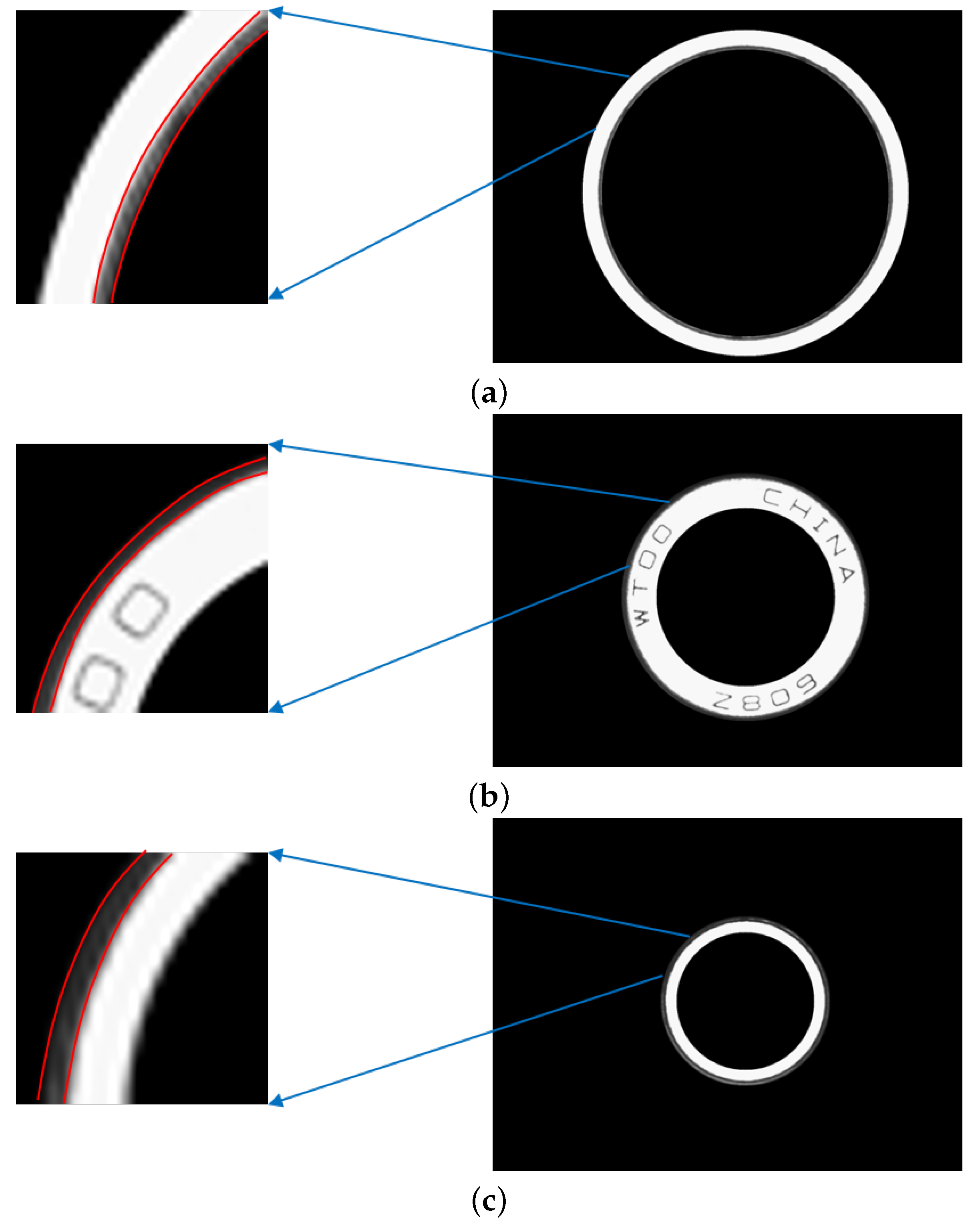
The reason for adopting segmentation based on a fixed ratio is described below. Once the outer ring, inner ring, or dust cover divided by the standard bearing ratio deviates, there must be a dimension defect. SERDD performs abnormal dimension detection here. Since the inside and outside edges of the three parts are in low gray value, we only need to count the number of low-gray pixels in the edge regions to determine whether there is a dimension defect, as shown in Figure 6.

3.5. Polar to Cartesian (P2C) Coordinate Transformation

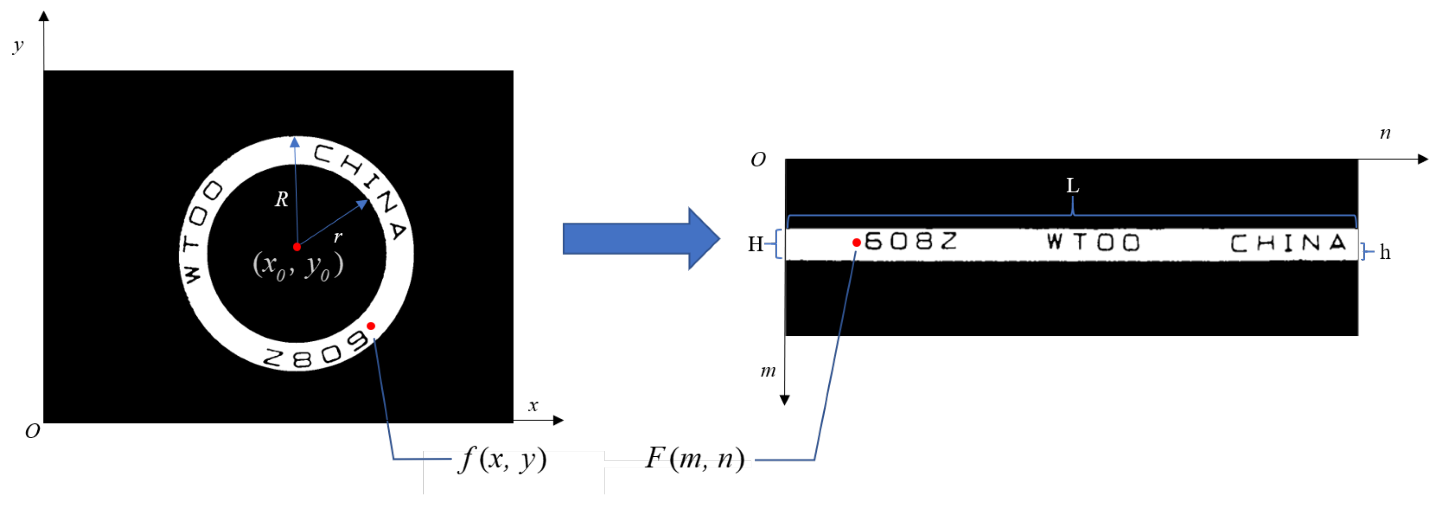
The three regions are all in the shape of a ring. In order to facilitate subsequent character recognition and defect detection, we introduced Polar to Cartesian (P2C) coordinate transformation [27] to transform the ring into a more tractable rectangular band.
As shown in Figure 7, R is the outer radius of the ring, r is the inner radius of the ring, H is the width of the rectangular band, L is the length of the rectangular band, and f ( x , y ) is the coordinate point somewhere on the ring, F ( m , n ) is the point of the rectangular band corresponding to f ( x , y ) , m and n are the numbers of rows and columns of the band (the upper left corner of the rectangular band is (0,0)), and h is the height of F ( m , n ) in the band.
The corresponding relationship is as follows:
x = x 0 ± ( r + h ) cos θ y = y 0 ± ( r + h ) sin θ
H = R r
L = 2 π R
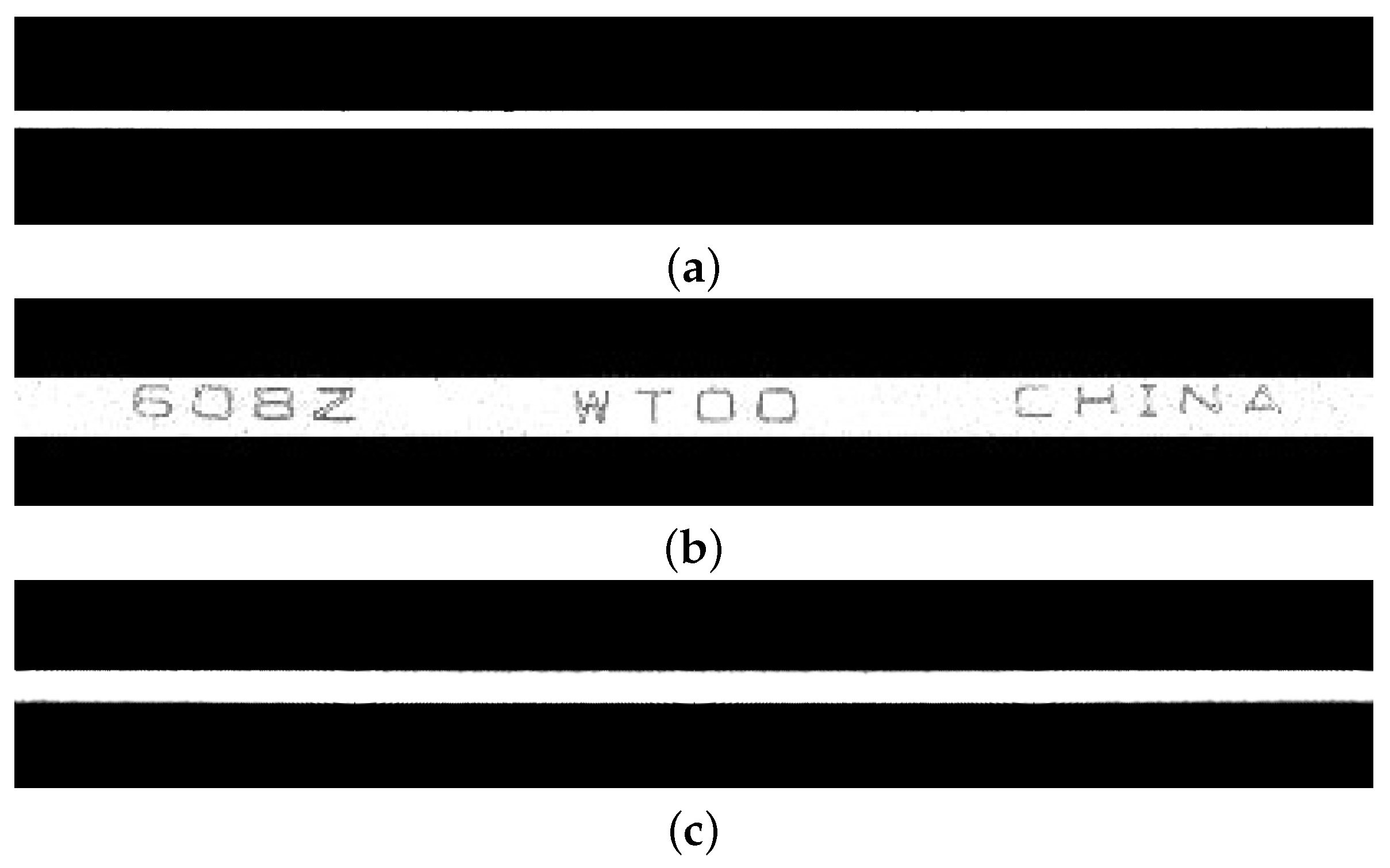
After P2C, we can convert the three-part image in Figure 5 into the rectangular band image in Figure 8.

3.6. Image Self-Stitching-And-Cropping (ISSC)

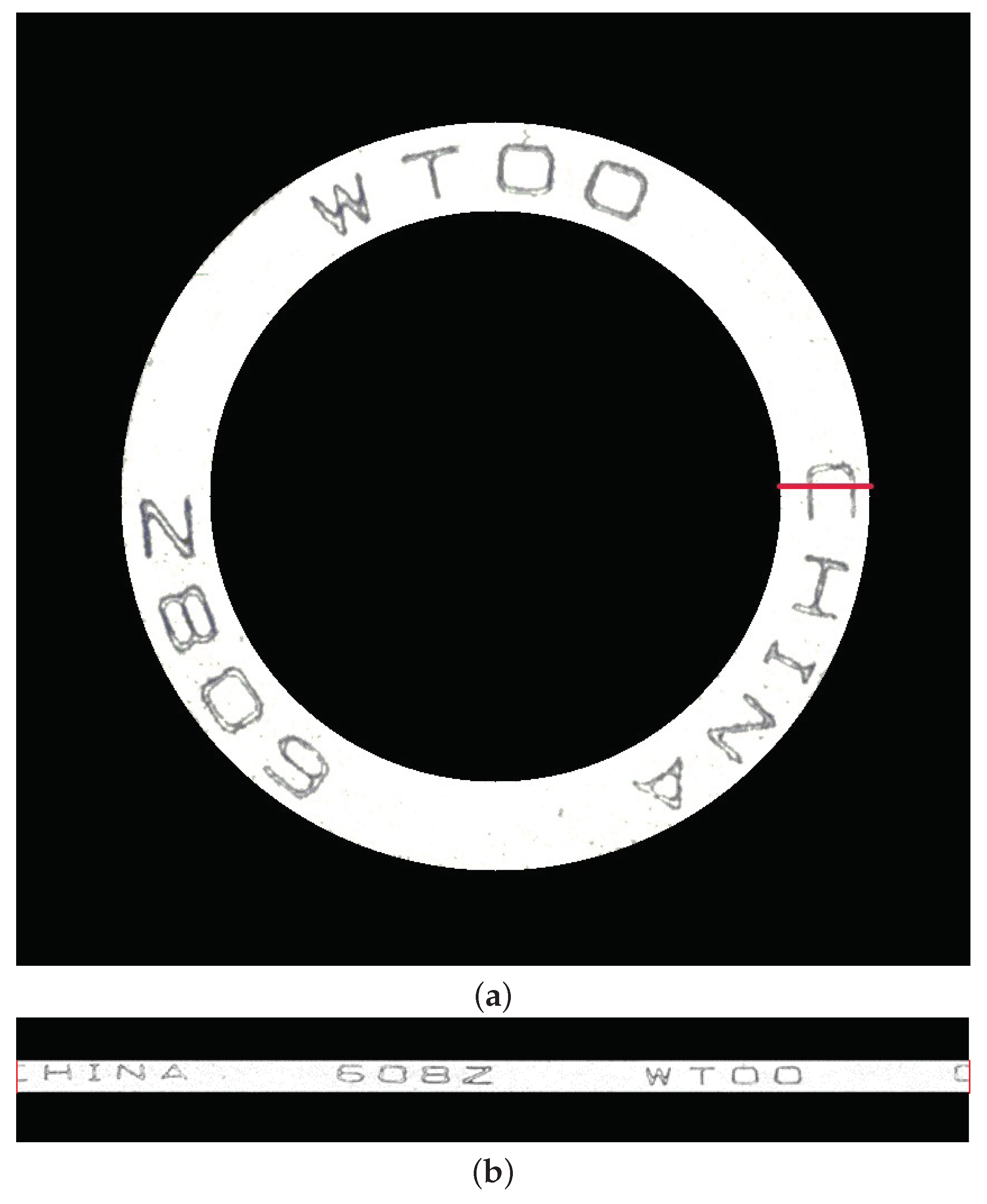
Unlike the outer and inner rings, the dust cover has engraved characters whose grayscale performance is nearly the same as defects. Thus, they need to be removed through character recognition. P2C cut a ring at the polar axis direction and convert it into a rectangular band. Once a character crosses the polar axis, as shown in the red line of Figure 9a, it will be cut during P2C. As shown in Figure 9b, “C” is cut so that the subsequent character recognition will fail to recognize “C” normally.
In the actual industrial site, the bearings’ placement is random, so it is impossible to avoid the problem of characters being cut.
Liu [20] proposes a band expansion method based on character width to solve the problem of the character being cut. This method restores the cut characters but retains the characters’ cut parts and may cut another character again. Chen [28] does not use P2C but counts the binary histograms every a short distance on the dust cover, rotates the dust cover until the histograms match the template’s histograms, and then separates the character region. Due to the difficulty of this matching, the performance is not satisfactory enough.
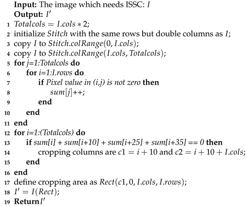
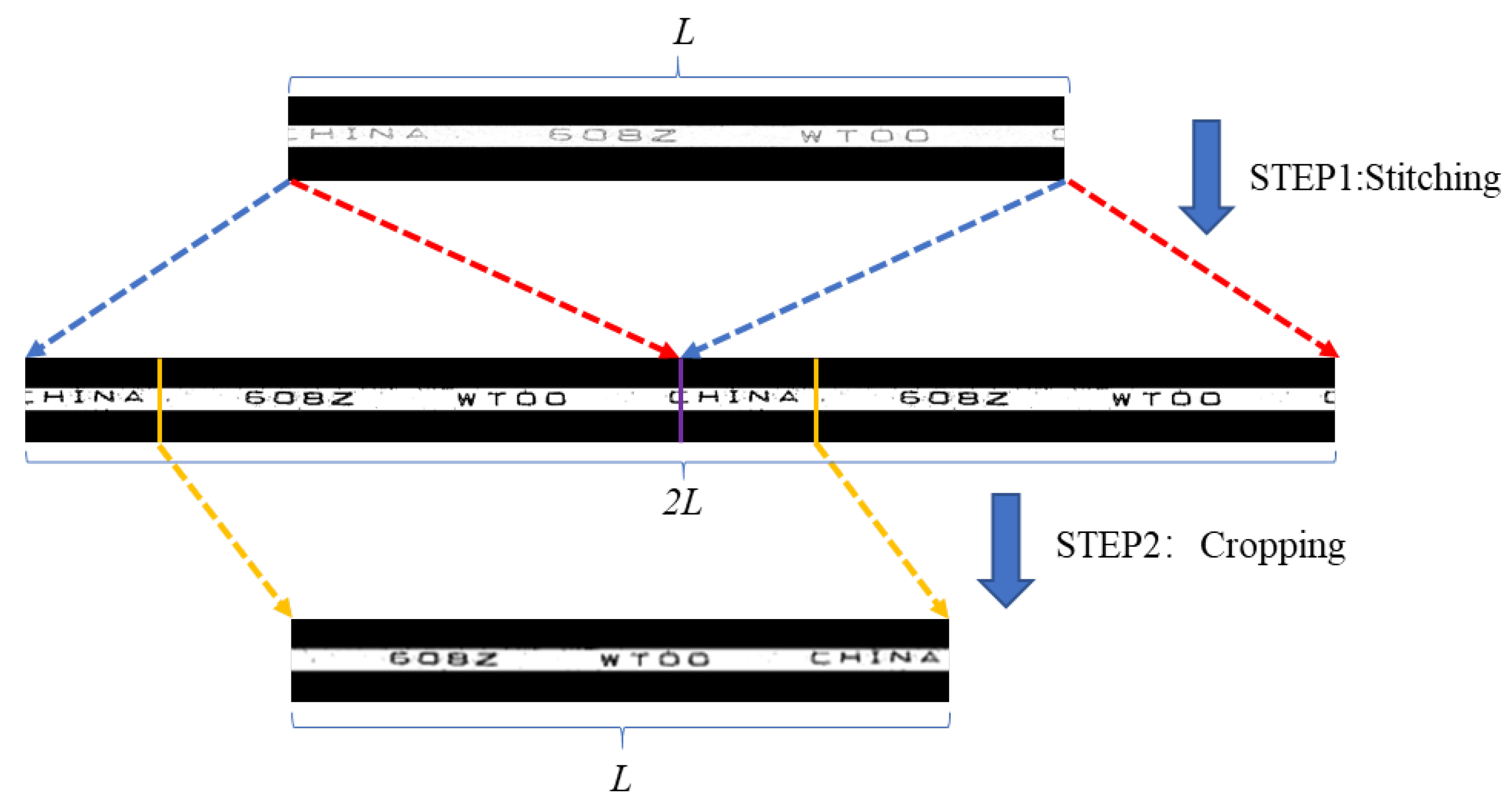
ISSC proposed in this paper can perfectly solve the problem of a character being cut. It is divided into two steps: stitching and cropping. In the stitching step, the band acquired in P2C is copied and horizontally stitched, which can restore the original cut character in the center of the “new band”. In the cropping step, a simple binary segmentation is used to distinguish between foreground and background roughly. The pixel value of the foreground becomes 0, and the pixel value of the background is 255. After that, the cropping position is located by counting the pixel number of foreground in every column. If the pixel number of foreground in a column does not exceed a certain threshold, the column is a background region, which means the cropping position can be set in this column. The distance between another cropping position and this cropping position is the length of the original band. After these two steps, a new band without any cut character is acquired.
Figure 10 shows the performance of this method from an example. First, the original image is copied and horizontally stitched, increasing the length of the band from the original L to 2 L and restoring the original cut character at the purple column in the figure. After the binary segmentation, black pixels in every column of the band are counted from left to right. Once the number of black pixels in a certain column does not exceed a certain threshold, the column is a background region, as shown at the left yellow column in the figure. A L-length band is cropped from the left yellow column to the right one to get a complete band without any cut character.
Compensation light-reflection and color attenuation may create redundant contours, which may disturb the segmentation. However, the cropping position can only be located at a certain column without any contours. Thus, all the columns with normal and redundant contours are excluded. So compensation light-reflection and color attenuation cannot influence the performance of ISSC.
This method can effectively retain all the information of the original image without adding redundant information. Figure 11 and Algorithm 1 shows the process.
Algorithm 1: ISSC
Machines 09 00040 i001

3.7. Threshold Segmentation

The grayscale image cannot accurately extract characters or defects, so we need to perform binary segmentation on the image. The binary segmentation method we use is the OTSU algorithm [29,30,31]. Assuming that the band has N pixels, m is the pixels occupied by the foreground (characters or defects), n is the pixels occupied by the background, and T is the set threshold, then:
w 0 = m N
w 1 = n N
σ T 2 = w 0 ( μ 0 μ T ) 2 + w 1 ( μ 1 μ T ) 2
w 0 and w 1 respectively represent the proportion of foreground and background pixels, μ 0 and μ 1 respectively represent the average gray levels of foreground and background pixels. μ T and σ T 2 respectively represent the overall average and variance when T is the set threshold. The OTSU algorithm traverses the threshold from 0 to 255 and finds T O T S U which makes σ T 2 the largest, that is:
T O T S U = arg max T ( σ T 2 )
The OTSU algorithm segments gray images by finding the threshold that maximizes the variance between foreground and background. It can quickly and accurately segment characters, defects, and backgrounds due to the apparent differences between characters and backgrounds in the image. Besides, it can increase the segmentation accuracy of some images, such as low saturation images.

3.8. The Removal of Small Connected Domains and Holes

After the threshold segmentation of the outer ring, dust cover, and inner ring bands, some noise or reflective spots are retained to form small white connected domains in the non-character regions and small black holes inside the characters. These connected domains and holes will interfere with the subsequent algorithms. Figure 12 demonstrates a removal example of connected domains and holes in a dust cover. It can be seen that all the small white connected domains in the non-character region have been removed [32], all the holes inside the characters have been filled, which is helpful for character extraction and recognition.

3.9. Character Extraction and Defect Detection of Non-Character Regions

3.9.1. Character Extraction

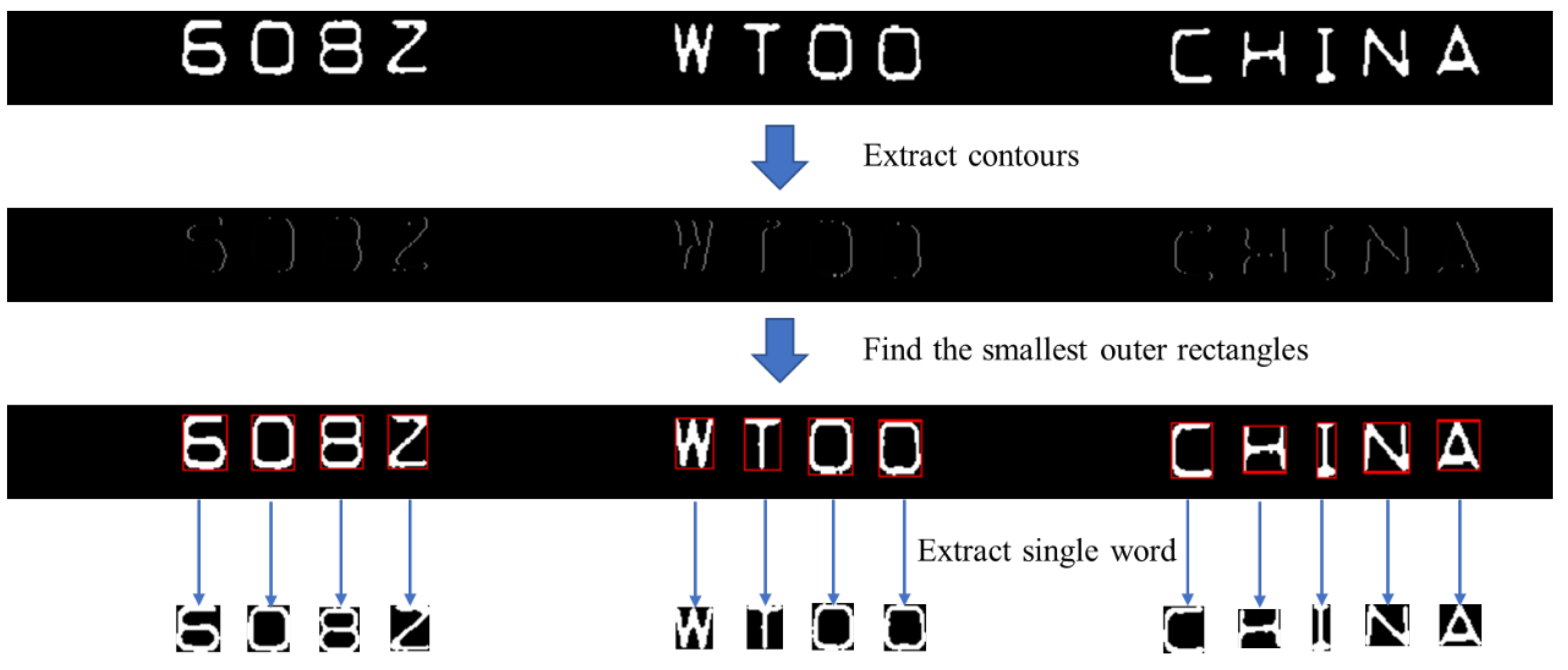
Before character recognition, each character needs to be extracted from the dust cover band. The first step is to extract all the contours in the band, but only keep the outermost contour [33]. The step ensures that each character has only one contour. The next step is to calculate the minimum bounding rectangle according to the outermost contour and crop each character. As shown in Figure 13.

3.9.2. Defect Detection of Non-Character Regions

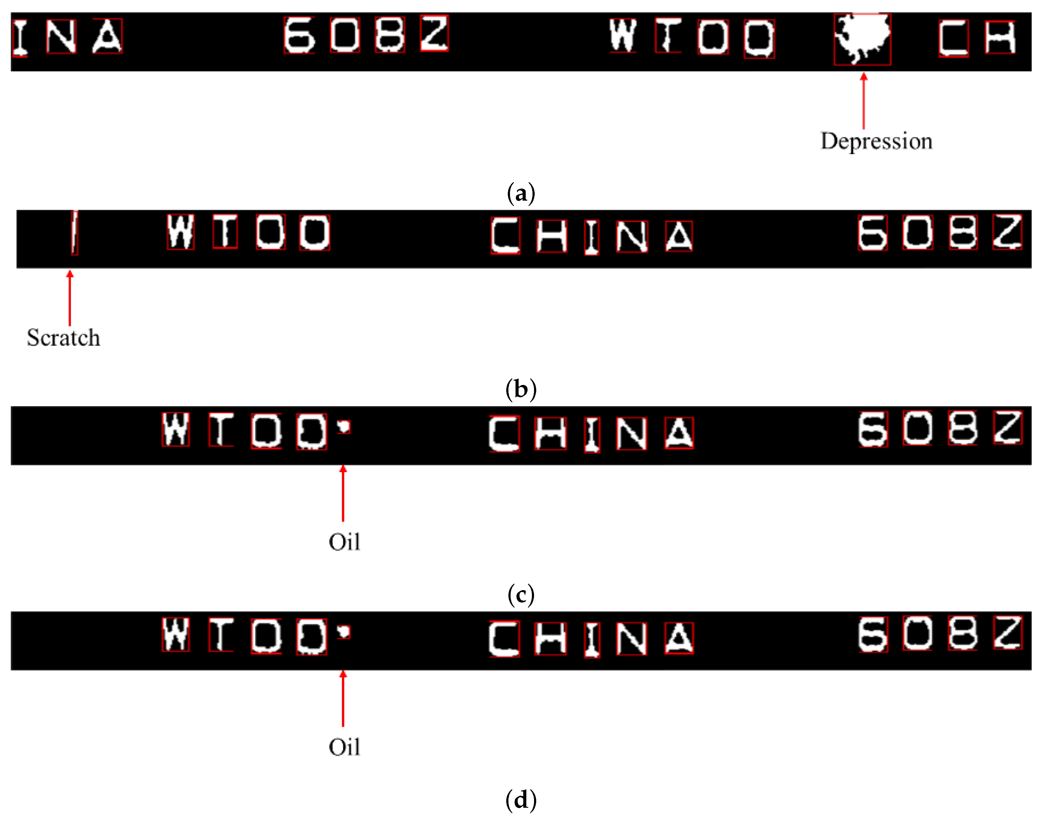
As can be seen from Figure 12, the bands have no noise, leaving probably only defects or characters. Therefore, in the character extraction step, characters can be easily found by contour extraction. It should be noted that if there is a defect in the band, the defect contour will also be extracted as a character candidate. Before character cropping, a simple step of contour counting function is added. Suppose the number of contours is not equal to the original number of characters in the band. In that case, it can be judged that there is a defect in the non-character region (defects may lead to adhesion of two character contours, and this step can also detect such character defects). For example, the normal band has 13 characters: WTOO 608Z CHINA, so the number of contours in the band is 13. Once the number of contours of a band is more than 13, the situation is abnormal regardless of whether the extra contour is a character or a defect. Some instances are shown in Figure 14. Additionally, there is a scenario: a defect adds one contour, and due to another defect, one character is removed from the bearing surface. The algorithm cannot detect this defect. However, this defect is classified as a character defect and can be detected by the character recognition method in the following section.
Defects such as depressions, scratches, and oil can all be detected in this step. There are no characters on the outer and inner rings, so it must be a defect as long as any contour is extracted.

3.10. Character Recognition and Defect Detection of Characters

3.10.1. Character Recognition

The existing machine vision literature adopts targeted character recognition methods [34]. Liu [20] trains 50 samples with a small neural network, and it can classify seven classes of characters and defective characters. Shen [21] divides each character into 3 × 3 cells, calculates the proportion of the character part in each small cell as a feature vector, and then recognizes the character by 2-norm of the difference between the template feature vector and this feature vector. Chen’s method [22] rotates and matches character regions through cross-correlation coefficients. Then it recognizes characters through the moment invariant features of the character edge envelopes. According to the position, division, and normalization features of characters, Wang [34] uses LabVIEW’s virtual instrument technology and image processing technology to recognize characters.
This paper proposes a character recognition method based on Spatial Pyramid Character Proportion Matching (SPCPM). Inspired by Shen’s method [21], this method identifies whether the character is correct by character proportion matching. It has been found by experiments that the character recognition method of Shen [21] cannot detect all the defects on characters, and it is easy to confuse different characters like “8” and “6”. Moreover, we have found inspiration from the improvement from HOG [35] to PHOG [36,37] and given the sense of “space” and “level” to character features, namely adding the concept of Spatial Pyramid Matching (SPM) [38,39]. This method enriches and concretizes the features and further increases the difference of different characters so as to recognize each character more accurately and identify whether there are defects on the characters more accurately.
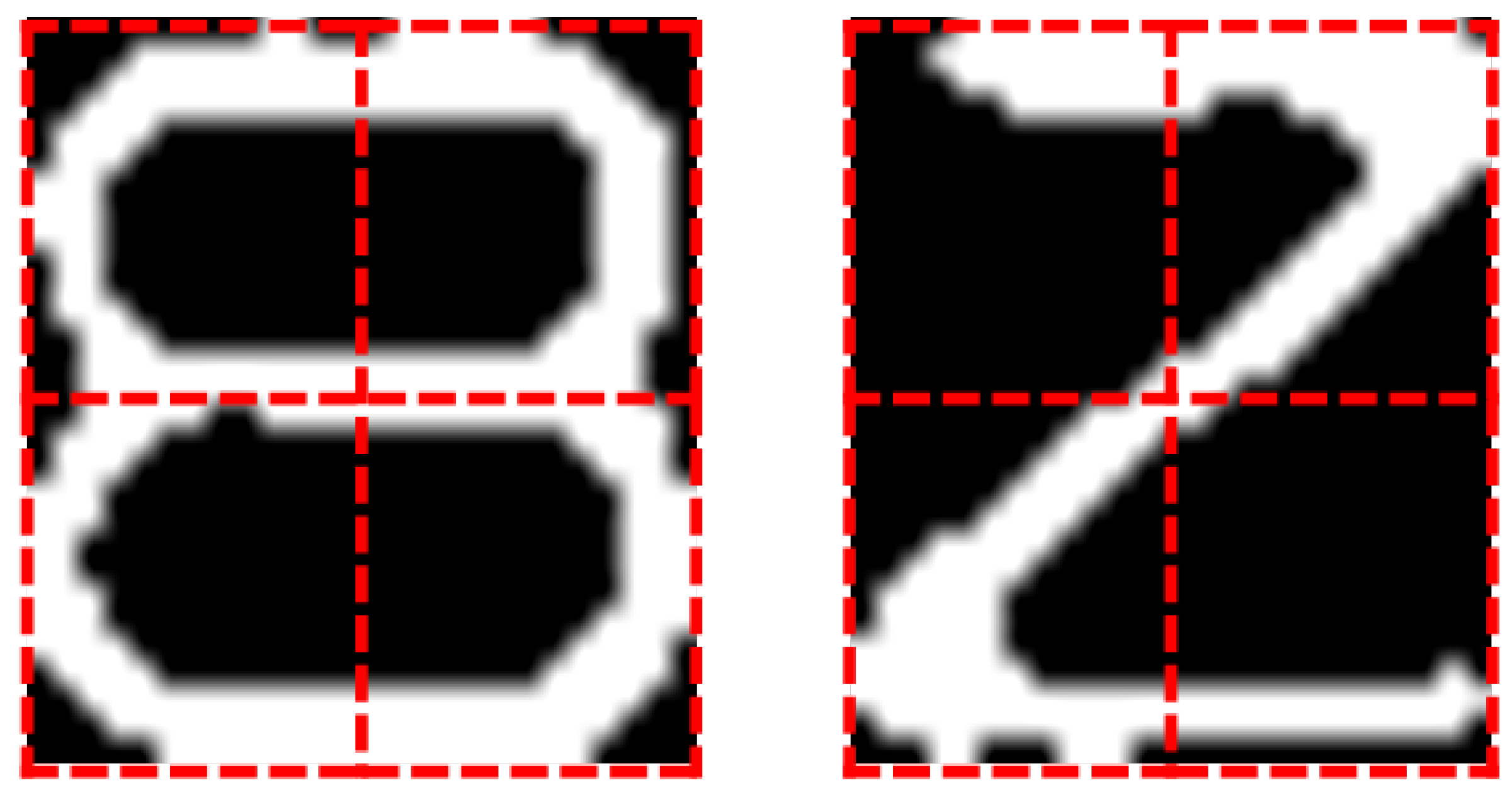
To get the character proportion features, it divides a single character into m × n cells firstly, as shown in Figure 15.
Assuming a pixel p in the i-th cell, since the image is binary, the value of p can only be 0 or 255. The proportion of character in this cell can be calculated by Formula (10).
C i = n ( p = 255 ) n ( p = 0 ) + n ( p = 255 )
Here, n ( p = 255 ) , n ( p = 0 ) respectively represent the pixel number of character and the pixel number of background. After obtaining the proportion of each cell, combine them into a 1 × ( m × n ) vector, which is the feature vector of this character, as shown in Equation (11).
C = [ C 1 , C 2 , , C m × n ]
Here, C is the feature vector of this character.
Finally, the 2-norm of the difference between template feature vector C t and C is calculated. If the 2-norm is less than a certain threshold, it means that the characters match successfully. Otherwise, the recognition fails. The calculation of the two norms is as Equation (12).
C C t 2 = i = 1 m × n ( C C t ) i 2
To improve the accuracy of character matching and recognition, SPM [38,39] has been introduced. SPM divides the image into several cells and calculates the feature information of each cell. Meanwhile, a multi-scale segmentation method is adopted to extract different fine-grained feature information.
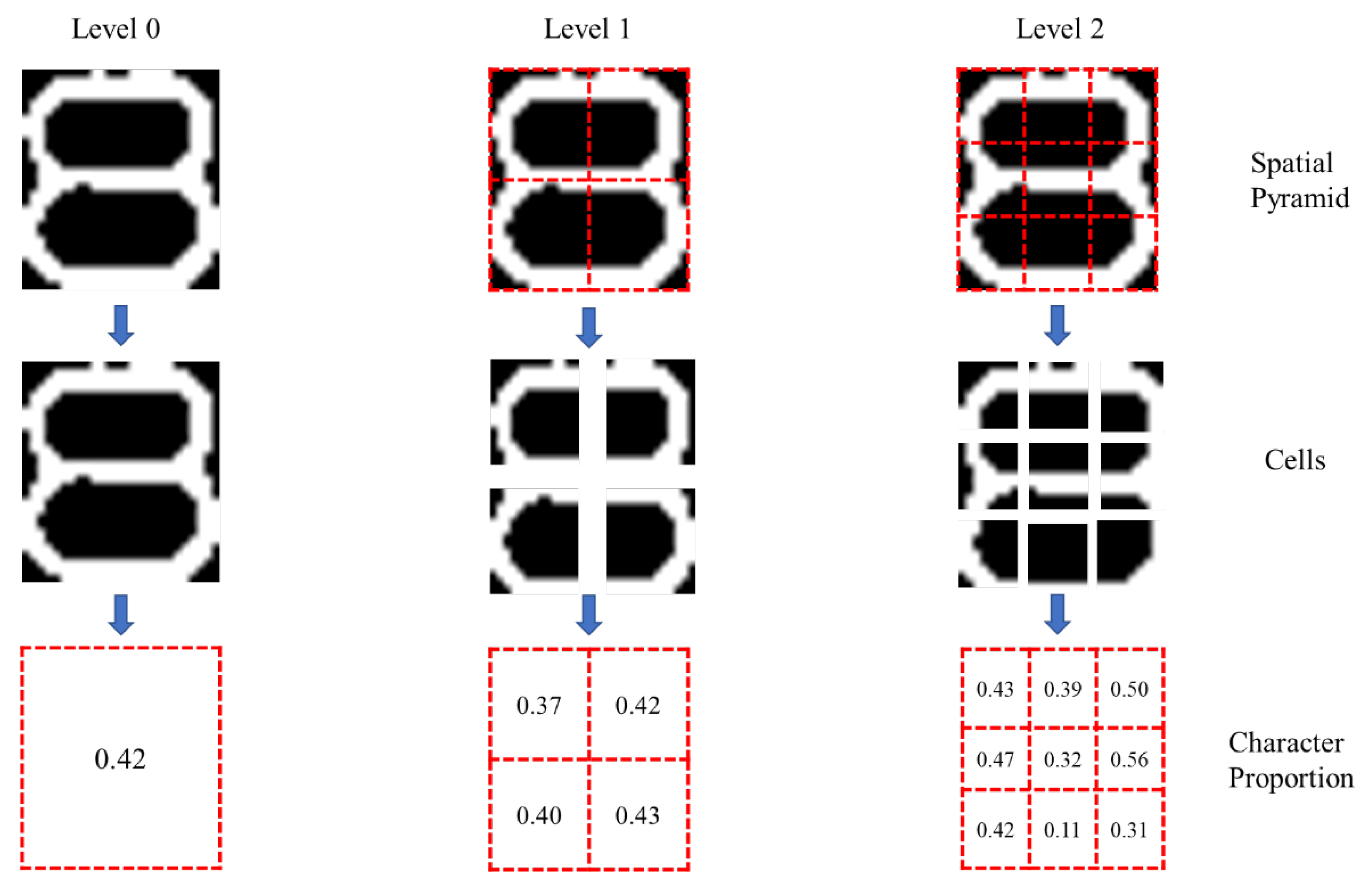
SPCPM divides characters into several scales. For example, as shown in Figure 16, the character “8” is divided into 1 × 1 , 2 × 2 , 3 × 3 cells. The character proportion of each cell in each scale is still calculated by Formula (10) and the feature vector is still calculated by Formula (11).
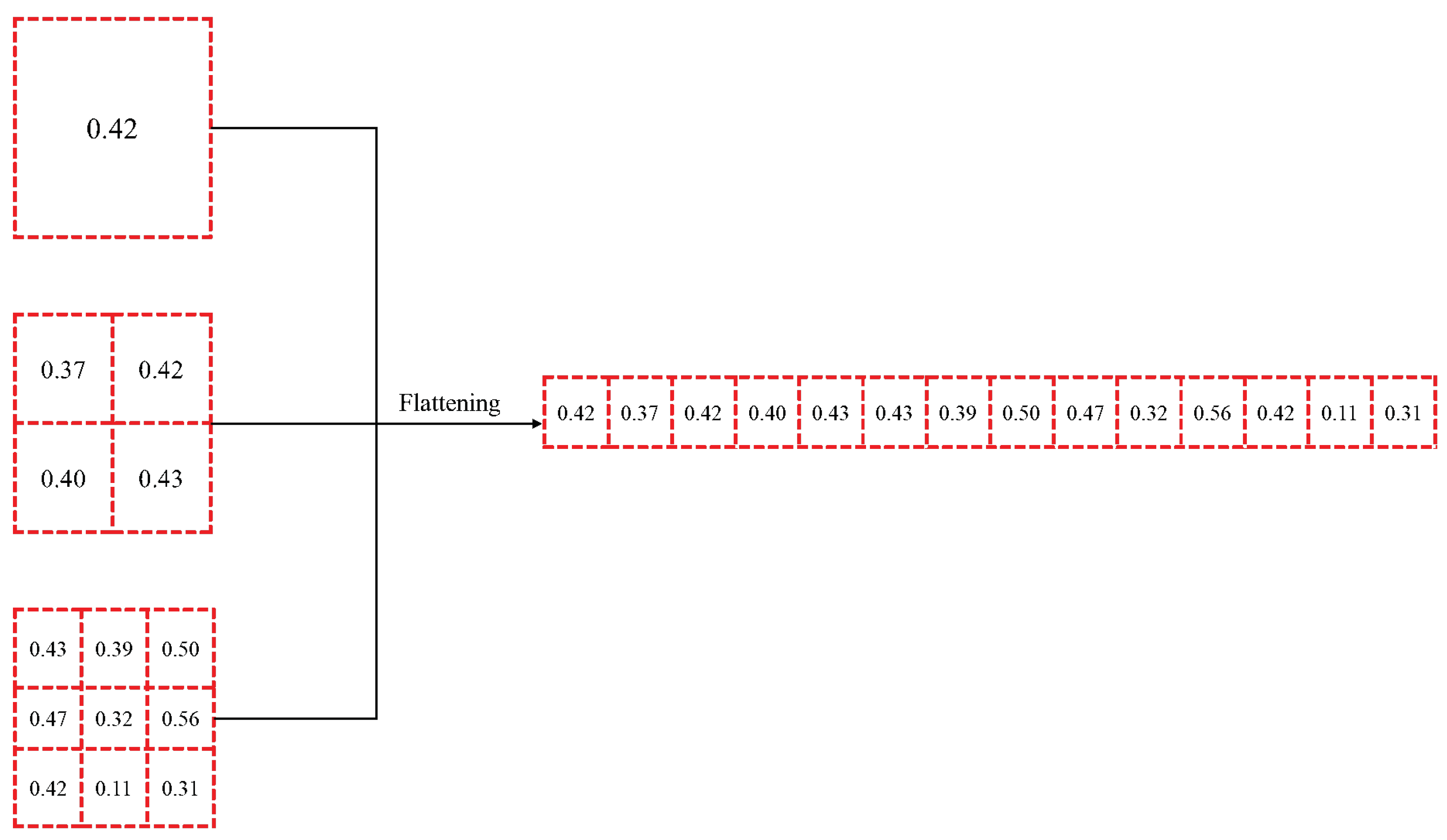
Assuming that the feature vectors corresponding to different scales is C 1 × 1 , C 2 × 2 , ⋯, C k × k , then these feature vectors are flattened into one-dimensional vector, as shown in Formula (13). Figure 17 intuitively reflects this process.
[ C 1 × 1 ] [ C 2 × 2 ] [ C k × k ] [ C 1 × 1 , C 2 × 2 , , C k × k ] = C multi scale
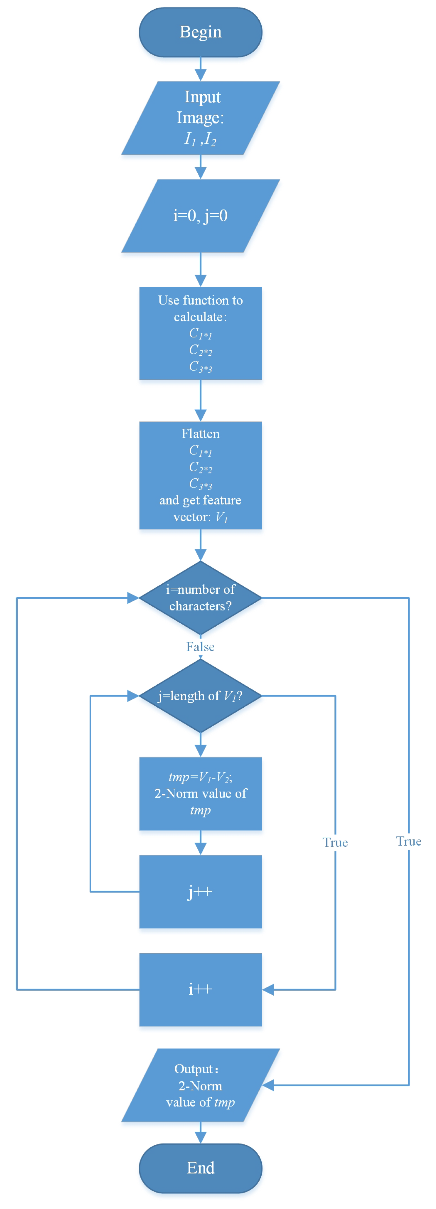
Finally, character proportion matching is achieved by Equation (12). The whole process is as shown in Figure 18 and Algorithm 2.
Algorithm 2: SPCPM
Machines 09 00040 i002
Character proportion is the statistical information of image features, which lacks structural information of image features, and Spatial Pyramid makes up for this weakness. Moreover, owing to the existence of hierarchical features, the sensitivity of features increases. Therefore, SPCPM can improve the accuracy of character recognition and defect detection. Specific comparisons will be given in the experimental section.

3.10.2. Defect Detection of Characters

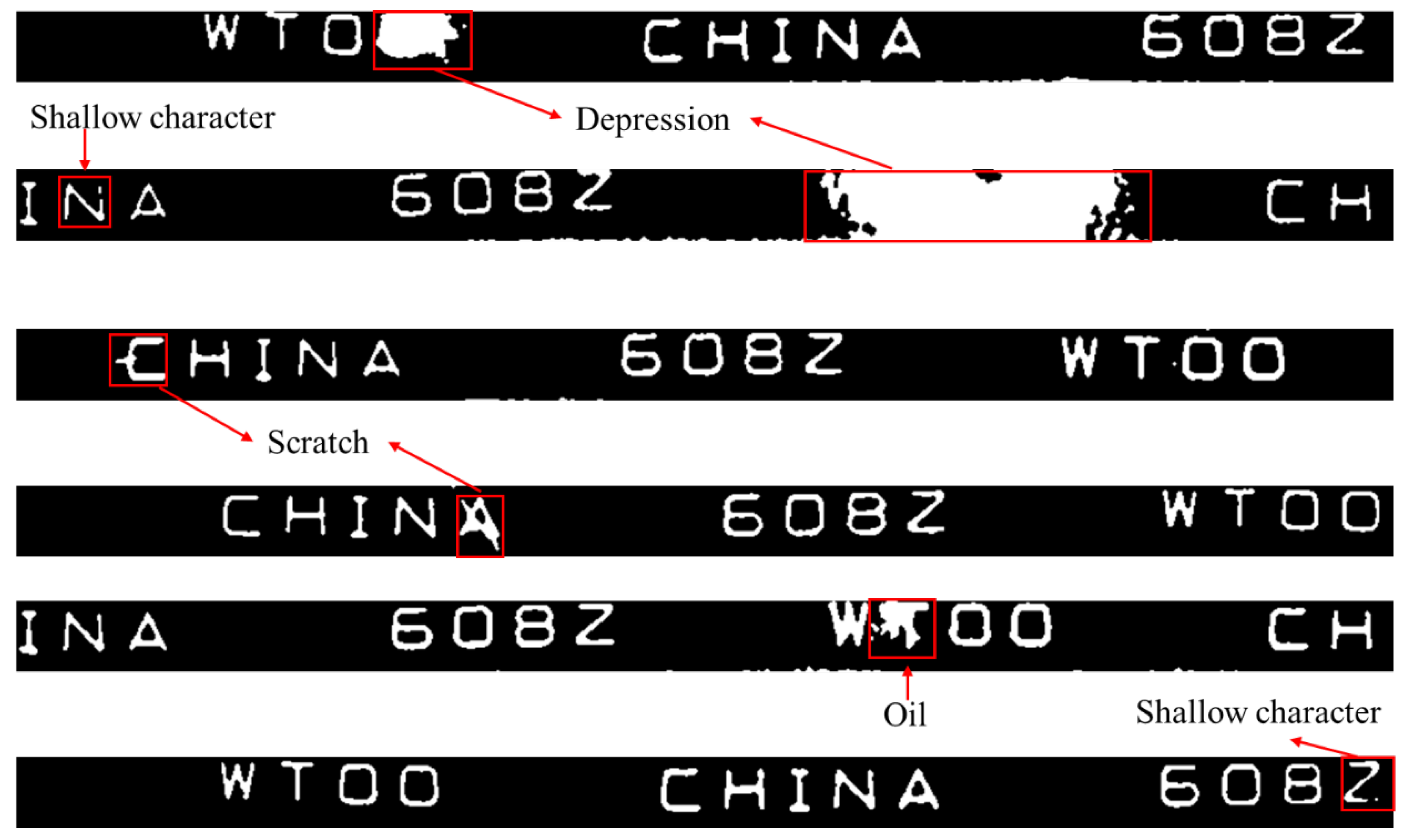
The character recognition in this paper is not only for recognizing characters but also for detecting character defects. The character recognition and defect detection work perfectly together here. Once the character to be recognized does not match any template character, it can be judged that the character has a defect. The defect detection process is the same as the previous section, so it will not be described here. Possible defects are depressions, scratches, and shallow characters, as shown in Figure 19.

4. Experimental Results

4.1. Experimental Setup

A suitable combination of image acquisition devices is used in this research. Firstly, according to the industrial field’s actual requirements, a CCD area-array camera with a resolution of 2 million pixels and a frame rate of 24 fps was chosen. Comparison and analysis of the effect of the combination of lens and light source on bearing surface defect detection were tested. Finally, a 25 mm prime lens and coaxial surface light source were assembled on the camera. All the parameters like exposure and brightness were set at proper values according to the actual situation to acquire high-quality images. The image acquisition devices could avoid the appearance of dark, blurred, low saturation, and low contrast images, reduce the complexity of the algorithm and improve the detection speed.
Because the authors of the two articles we compared did not provide the corresponding data set and there was no recognized bearing surface image data set, we could only conduct experiments and verify through our own data set. In this paper, 650 bearings produced by a bearing enterprise were used as experimental samples. The bearing specifications were the same, and the characters on the dust cover had two types: “608Z WTOO CHINA” and “608Z WTOO”. Among them, there were 483 standard bearing samples and 167 defective bearing samples. A total of 1285 effective bearing surface images were obtained, including 120 images with depressions, 82 images with scratches, 45 images with abnormal dimensions, 36 images with notches, 22 images with shallow characters, and 15 images with oil. All these bearing images were input into our algorithm for defect detection, and corresponding results could be obtained.
We measured the effectiveness and advancement of this method by the following indicators. The number of normal bearings was defined as N 1 , the number of successful detection of normal bearings was n 1 , the number of defective bearings was N 2 , and the number of successful detection of defective bearings was n 2 , then:
Detection accuracy of normal bearings R 1 is:
R 1 = n 1 N 1
Detection accuracy of defective bearings R 2 is:
R 2 = n 2 N 2
False alarm rate R 3 is:
R 3 = N 1 n 1 N 1
Missing alarm rate R 4 is:
R 4 = N 2 n 2 N 2

4.2. Results and Analysis of Defect Detection

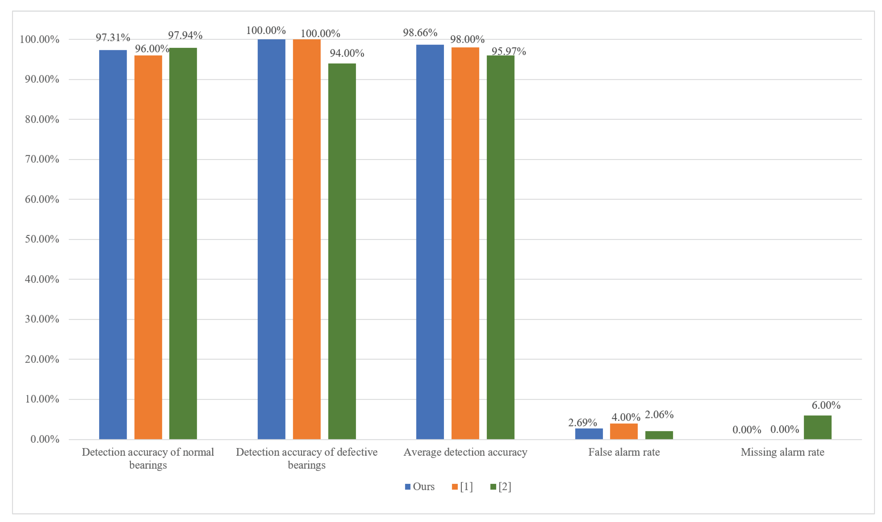
Table 1 shows the experimental results obtained by testing with all the collected images. In the actual bearing defect detection process, detection accuracy was more important than false alarm and missing alarm because the detection error was the alarm source. Lowering the rate of error was the most fundamental way to lower the alarm. So the primary aim of SERDD was to control the detection error. Moreover, a missing alarm was more significant than a false alarm because missing detection made the defective bearings enter the market. Once the defective bearings were assembled on the machines, it would bring huge security risks. Therefore, we have further tightened the basis for determining defects in each step of SERDD and finally achieved zero missing alarm results. We sorted out the experimental data in the paper [20,21] and compared them with our results, as shown in Figure 20.
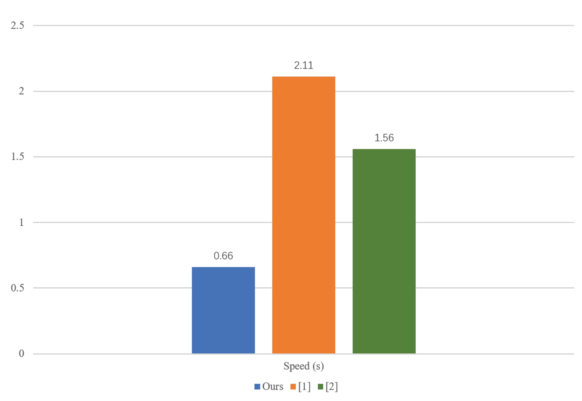
It can be seen from the figure that the false alarm rate of the paper [20] was the highest, reaching 4%. The false alarm rate of paper [21] was relatively low, only 2.06%, but its missing alarm rate was 6%, which is not allowed in actual detection. The experimental results of ours were as follows: the detection accuracy of normal bearings was 97.31%, the detection accuracy of defective bearings was 100%, the average detection accuracy was 98.66%, the false alarm rate was controlled at 2.69%, and the missing alarm rate was 0%. It should be noted that the average detection accuracy was 0.66% higher than [20] and 2.69% higher than [21]. The detection accuracy of normal bearings was slightly lower than that of the paper [21] and the false alarm rate was slightly higher than that of the paper [21]. This is because the missing alarm rate was controlled at 0%, which resulted in a partial loss of accuracy. In terms of processing speed, as shown in Figure 21, ref [20] took 2.11 s on average to detect a bearing image which resolution was 480 × 640 pixels and [21] took 1.56 s on average to detect a bearing image which resolution was 1600 × 1200 pixels. Thanks to SERDD, it took an average of 0.66 s to detect a bearing image which resolution was 1296 × 972 pixels. When the image resolution was at the same level, the speed of SERDD was more than twice that of state-of-the-art methods. Moreover, if SERDD detected defects at the first segment of SERDD, it took only 0.32 s. The time shown here includes the CPU time of processing the programs and reading the images.
Due to the segmented feature of SERDD, we adopted separate tests for each step of SERDD. For the four defect detection parts, we chose 100 targeted bearing images, respectively. In order to simulate the actual situation as much as possible, the 100 images contained defects to be detected and contained various other defects. The results of the four defect detection parts are shown in Table 2, Table 3, Table 4 and Table 5 respectively.
It can be seen from Table 2, Table 3 and Table 4 that the detection of notches, abnormal dimensions, and defects in non-character regions could almost reach 100% accuracy. Only the detection of character defects has a 3.92% false alarm rate. We picked out these two wrong images and found that the characters detected incorrectly were both “N, I, A”. After a series of checks, it has been found that the feature vectors of these three characters were sensitive to the endpoints of these letters, which led to false alarms.

4.3. Experimental Results and Analysis of Character Recognition

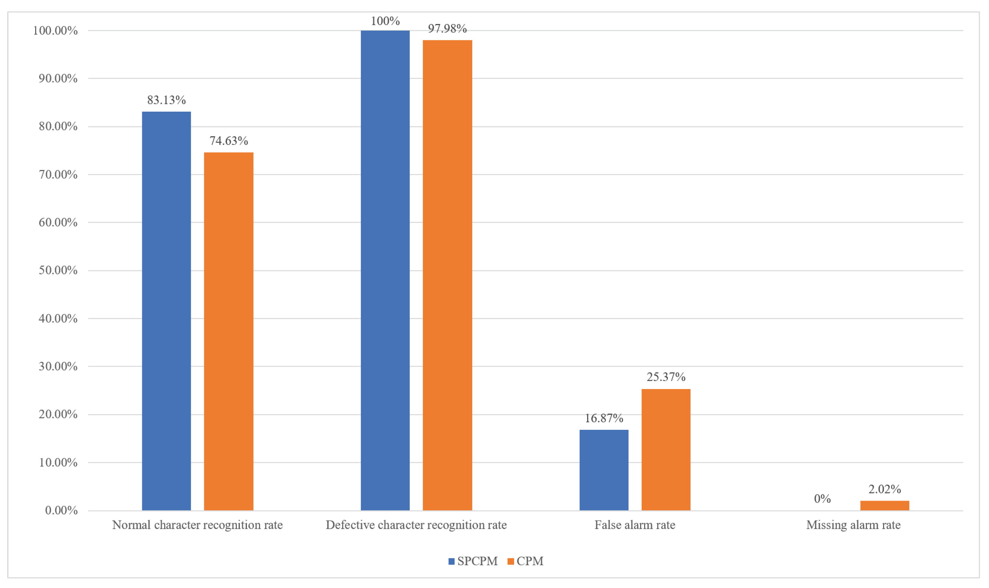
SPCPM proposed in this paper is an improvement and innovation method based on Shen’s method [21]. Therefore, we have rebuilt Shen’s method and conducted a set of control experiments with this article. The results are shown in Table 6 and Table 7.
The data in Table 6 and Table 7 are drawn as histograms for intuitive comparison, as shown in Figure 22. As shown in Figure 22, the SPCPM method is superior to the CPM method in all indicators. The normal character recognition accuracy improves by nearly 9%, and the false alarm rate reduces by 9 % accordingly. The defective character recognition rate increases to 100%, and the missing alarm rate declines to 0%.
It can be seen that neither SPCPM nor CPM had a high recognition accuracy for normal characters, and there were two reasons. First, under the influence of defects in non-character regions, the shape of characters changed slightly, resulting in the failure of recognizing the characters correctly. Second, in order to control the missing alarm rate, we had a relatively strict judgment basis for normal characters, and it was was to judge normal characters as defective characters. It is found that most of the normal character recognition errors were caused by defects in non-character regions, which could be detected before character recognition, so the overall defect detection accuracy was not affected. Besides, we also tested character recognition of Tesseract [40], the mainstream OCR system, and the results were not satisfactory. The overall recognition rate of Tesseract was about 52%.

5. Conclusions

The research work in this paper aims at detecting bearing surface defects, and this paper proposes a novel surface defect detection method, Segmented Embedded Rapid Defect Detection Method for Surface Defects (SERDD). This method has the advantages of high speed, high accuracy, high portability, low error, and low cost. In this method, defect detection is embedded and fused into specific suitable image processing steps to complete image processing and defect detection tasks at the same time. This paper also proposes Image Self-Stitching-and-Cropping (ISSC) to prevent characters from being cut. Moreover, this paper proposes a method of character recognition based on Spatial Pyramid Character Proportion Matching (SPCPM), which can efficiently and accurately recognize specific characters. Experiments have proved that the algorithm can accurately and quickly detect defects such as depressions, scratches, notches, oil, shallow characters, abnormal dimensions on the bearing, and is state-of-the-art in peer research.
However, much follow-up work remains to be done:
  • Improve the accuracy of SPCPM.
  • Deal with some possible situations of particular defects.
  • Set up the related execution equipment to build a defect detection system for bearing surface defects.

Author Contributions

Conceptualization, S.S.; methodology, L.L. and S.S.; software, L.L., Y.Z. and H.L.; validation, L.L. and H.X.; formal analysis, L.L. and S.S.; investigation, L.L., Y.Z. and H.L.; resources, S.S.; data curation, L.L. and Y.Z.; writing—original draft preparation, L.L.; writing—review and editing, L.L. and H.X.; visualization, L.L.; supervision, S.S.; project administration, S.S.; funding acquisition, H.X. and S.S. All authors have read and agreed to the published version of the manuscript.

Funding

This research is supported by the Innovation Project of Shanghai Institute of Technical Physics, Chinese Academy of Sciences (NO.X-209).

Acknowledgments

The author would like to express his heartfelt thanks to Jessica Wang for proofreading of this article.

Conflicts of Interest

The authors declare no conflict of interest.

References

  1. Wang, H.; Yang, J.; Hu, Z. Current Status and Prospect of Roller Bearing Surface Defect Detection. Procedia Eng. 2011, 15, 4331–4336. [Google Scholar] [CrossRef]
  2. Shah, D.S.; Patel, V.N. A Review of Dynamic Modeling and Fault Identifications Methods for Rolling Element Bearing. Procedia Technol. 2014, 14, 447–456. [Google Scholar] [CrossRef]
  3. El-Thalji, I.; Jantunen, E. A summary of fault modelling and predictive health monitoring of rolling element bearings. Mech. Syst. Signal Process. 2015, 60–61, 252–272. [Google Scholar] [CrossRef]
  4. Randall, R.B.; Antoni, J. Rolling element bearing diagnostics—A tutorial. Mech. Syst. Signal Process. 2011, 25, 485–520. [Google Scholar] [CrossRef]
  5. Peng, Z.; Tse, P.W.; Chu, F. A comparison study of improved Hilbert–Huang transform and wavelet transform: Application to fault diagnosis for rolling bearing. Mech. Syst. Signal Process. 2005, 19, 974–988. [Google Scholar] [CrossRef]
  6. Randall, R.; Antoni, J.; Chobsaard, S. The relationship between spectral correlation and envelope analysis in the diagnostics of bearing faults and other cyclostationary machine signals. Mech. Syst. Signal Process. 2001, 15, 945–962. [Google Scholar] [CrossRef]
  7. Lou, X.; Loparo, K.A. Bearing fault diagnosis based on wavelet transform and fuzzy inference. Mech. Syst. Signal Process. 2004, 18, 1077–1095. [Google Scholar] [CrossRef]
  8. Li, B.; Chow, M.; Tipsuwan, Y.; Hung, J. Neural-network-based motor rolling bearing fault diagnosis. IEEE Trans. Ind. Electron. 2000, 47, 1060–1069. [Google Scholar] [CrossRef] [Green Version]
  9. Samanta, B.; Al-Balushi, K. Artificial neural network based fault diagnostics of rolling element bearings using time-domain features. Mech. Syst. Signal Process. 2003, 17, 317–328. [Google Scholar] [CrossRef]
  10. Lei, Y.; Jia, F.; Lin, J.; Xing, S.; Ding, S. An Intelligent Fault Diagnosis Method Using Unsupervised Feature Learning Towards Mechanical Big Data. IEEE Trans. Ind. Electron. 2016, 63, 3137–3147. [Google Scholar] [CrossRef]
  11. Cao, H.; Li, D.; Yue, Y. Root Cause Identification of Machining Error Based on Statistical Process Control and Fault Diagnosis of Machine Tools. Machines 2017, 5, 20. [Google Scholar] [CrossRef] [Green Version]
  12. Zenzen, R.; Khatir, S.; Belaidi, I.; Le Thanh, C.; Abdel Wahab, M. A modified transmissibility indicator and Artificial Neural Network for damage identification and quantification in laminated composite structures. Compos. Struct. 2020, 248, 112497. [Google Scholar] [CrossRef]
  13. Khatir, S.; Boutchicha, D.; Le Thanh, C.; Tran, H.; Nguyen, N.; Abdel Wahab, M. Improved ANN technique combined with Jaya algorithm for crack identification in plates using XIGA and experimental analysis. Theor. Appl. Fract. Mech. 2020, 107, 102554. [Google Scholar] [CrossRef]
  14. Jiang, Y.; Tang, C.; Zhang, X.; Jiao, W.; Huang, T. A novel rolling bearing defect detection method based on bispectrum analysis and cloud model-improved EEMD. IEEE Access 2020, 8, 24323–24333. [Google Scholar] [CrossRef]
  15. Li, C.; Sanchez, V.; Zurita, G.; Cerrada Lozada, M.; Cabrera, D. Rolling element bearing defect detection using the generalized synchrosqueezing transform guided by time–frequency ridge enhancement. Isa Trans. 2016, 60, 274–284. [Google Scholar] [CrossRef]
  16. Wang, J.; He, Q.; Kong, F. A new synthetic detection technique for trackside acoustic identification of railroad roller bearing defects. Appl. Acoust. 2014, 85, 69–81. [Google Scholar] [CrossRef]
  17. Anil, K.; Yuqing, Z.; Gandhi, C.P.; Rajesh, K.; Jiawei, X. Bearing defect size assessment using wavelet transform based Deep Convolutional Neural Network (DCNN). Alex. Eng. J. 2020, 59, 999–1012. [Google Scholar]
  18. Udmale, S.S.; Singh, S.K.; Bhirud, S.G. A bearing data analysis based on kurtogram and deep learning sequence models. Measurement 2019, 145, 665–677. [Google Scholar] [CrossRef]
  19. Fu, X.; Li, K.; Liu, J.; Li, K.; Chen, C. A Two-Stage Attention Aware Method for Train Bearing Shed Oil Inspection Based on Convolutional Neural Networks. Neurocomputing 2019, 380, 212–224. [Google Scholar] [CrossRef]
  20. Liu, B.; Yang, Y.; Wang, S.; Bai, Y.; Yang, Y.; Zhang, J. An automatic system for bearing surface tiny defect detection based on multi-angle illuminations. Optik 2020, 208, 164517. [Google Scholar] [CrossRef]
  21. Shen, H.; Li, S.; Gu, D.; Chang, H. Bearing defect inspection based on machine vision. Measurement 2012, 45, 719–733. [Google Scholar] [CrossRef]
  22. Xiangwei, C.; Xuejun, Z.; Shan, G. Inspection of Surface Defect of Micro Bearing Based on Computer Vision. Mach. Tool Hydraul. 2009, 37, 130–132. [Google Scholar]
  23. Deng, S.; Cai, W.; Xu, Q.; Liang, B. Defect detection of bearing surfaces based on machine vision technique. In Proceedings of the 2010 International Conference on Computer Application and System Modeling (ICCASM 2010), Taiyuan, China, 22–24 October 2010; pp. 548–554. [Google Scholar] [CrossRef]
  24. Li, Z.; Zhang, J.; Zhuang, T.; Wang, Q. Metal surface defect detection based on MATLAB. In Proceedings of the 2018 IEEE 3rd Advanced Information Technology, Electronic and Automation Control Conference (IAEAC), Chongqing, China, 1 October 2018; pp. 2365–2371. [Google Scholar]
  25. Peng, G.; Zhang, Z.; Li, W. Computer vision algorithm for measurement and inspection of O-rings. Measurement 2016, 94, 828–836. [Google Scholar] [CrossRef]
  26. Kong, H.; Yang, J.; Chen, Z. Accurate and efficient inspection of speckle and scratch defects on surfaces of planar products. IEEE Trans. Ind. Inform. 2017, 13, 1855–1865. [Google Scholar] [CrossRef]
  27. Chiou, Y.C.; Li, W.C. Flaw detection of cylindrical surfaces in PU-packing by using machine vision technique. Measurement 2009, 42, 989–1000. [Google Scholar] [CrossRef]
  28. Chiou, Y.C.; Li, W.C. Bearing shield surface defect detection based on machine vision. Comput. Eng. Appl. 2014, 50, 250–254. [Google Scholar] [CrossRef]
  29. Level Otsu, N. A threshold selection method from gray-level histogram. IEEE Trans. Syst. Man. Cybern. 1979, 9, 62–66. [Google Scholar] [CrossRef] [Green Version]
  30. TAO, Q.P.; WU, X.S. Rapid Detection Method of the Bearing Surface Defects. Microelectron. Comput. 2011, 10, 98–100, 104. [Google Scholar]
  31. Ng, H.F. Automatic thresholding for defect detection. Pattern Recognit. Lett. 2006, 27, 1644–1649. [Google Scholar] [CrossRef]
  32. Bei, L. One improved scan line seed-filling algorithm. In Proceedings of the China-ireland International Conference on Information & Communications Technologies, Dublin, Ireland, 28–29 August 2007. [Google Scholar]
  33. Suzuki, S.; be, K. Topological structural analysis of digitized binary images by border following. Comput. Vis. Graph. Image Process. 1985, 29, 396. [Google Scholar] [CrossRef]
  34. Hengdi, W.; Yang, Z.; Sier, D.; Erdong, S.; Yong, W. Bearing characters recognition system based on LabVIEW. In Proceedings of the 2011 International Conference on Consumer Electronics, Communications and Networks (CECNet), Xianning, China, 16–18 April 2011; pp. 118–122. [Google Scholar]
  35. Dalal, N.; Triggs, B. Histograms of oriented gradients for human detection. In Proceedings of the 2005 IEEE Computer Society Conference on Computer Vision and Pattern Recognition (CVPR’05), San Diego, CA, USA, 20–25 June 2005; pp. 886–893. [Google Scholar]
  36. Bosch, A.; Zisserman, A.; Munoz, X. Image classification using random forests and ferns. In Proceedings of the 2007 IEEE 11th International Conference on Computer Vision, Rio de Janeiro, Brazil, 14–21 October 2007; pp. 1–8. [Google Scholar]
  37. Bosch, A.; Zisserman, A.; Munoz, X. Representing shape with a spatial pyramid kernel. In Proceedings of the 6th ACM International Conference on Image and Video Retrieval, Amsterdam, The Netherlands, 9–11 July 2007; pp. 401–408. [Google Scholar]
  38. Lazebnik, S.; Schmid, C.; Ponce, J. Beyond bags of features: Spatial pyramid matching for recognizing natural scene categories. In Proceedings of the 2006 IEEE Computer Society Conference on Computer Vision and Pattern Recognition (CVPR’06), New York, NY, USA, 17–22 June 2006; pp. 2169–2178. [Google Scholar]
  39. Cao, Y.; Wang, C.; Li, Z.; Zhang, L.; Zhang, L. Spatial-bag-of-features. In Proceedings of the 2010 IEEE Computer Society Conference on Computer Vision and Pattern Recognition, San Francisco, CA, USA, 13–18 June 2010; pp. 3352–3359. [Google Scholar]
  40. Smith, R. An overview of the Tesseract OCR engine. In Proceedings of the Ninth International Conference on Document Analysis and Recognition (ICDAR 2007), Curitiba, Brazil, 23–26 September 2007; pp. 629–633. [Google Scholar]
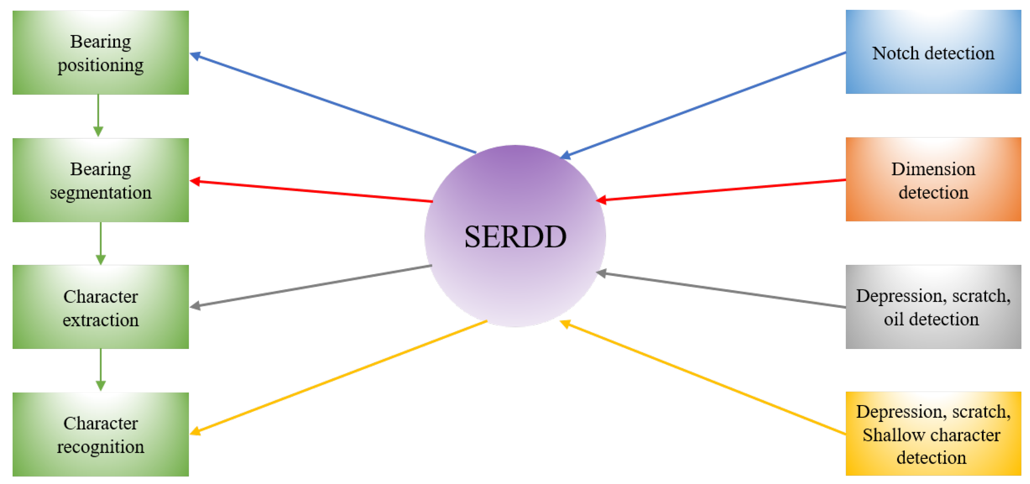
Figure 1. Schematic diagram of Segmented Embedded Rapid Defect Detection Method for Surface Defects (SERDD).
Machines 09 00040 g001
Figure 2. Algorithm flow of SERDD.
Machines 09 00040 g002
Figure 3. Bearing surface image.
Machines 09 00040 g003
Figure 4. Schematic diagram of a notch defect.
Machines 09 00040 g004
Figure 5. Segmentation of the outer ring, inner ring and dust cover of the bearing.
Machines 09 00040 g005
Figure 6. Abnormal dimension instances of outer ring, dust cover and inner ring. (a) Abnormal dimension instance of outer ring. (b) Abnormal dimension instance of dust cover. (c) Abnormal dimension instance of inner ring.
Machines 09 00040 g006
Figure 7. Polar to Cartesian coordinate transformation.
Machines 09 00040 g007
Figure 8. Results of Polar to Cartesian (P2C). (a) The rectangular band of outer ring. (b) The rectangular band of dust cover. (c) The rectangular band of inner ring.
Machines 09 00040 g008
Figure 9. An instance of a character being cut. (a) The character in the dust cover crosses the polar axis. (b) The character is cut after P2C.
Machines 09 00040 g009
Figure 10. Image Self-Stitching-and-Cropping (ISSC) process.
Machines 09 00040 g010
Figure 11. ISSC flowchart.
Machines 09 00040 g011
Figure 12. The removal process of small connected domains and holes in a dust cover.
Machines 09 00040 g012
Figure 13. Character extraction process.
Machines 09 00040 g013
Figure 14. Defects in the non-character regions. (a) Depression in the band of dust cover. (b) Scratch in the band of dust cover. (c) Oil in the band of dust cover. (d) Scratch in the band of outer ring.
Machines 09 00040 g014
Figure 15. Character segmented into 2 × 2 cells.
Machines 09 00040 g015
Figure 16. An instance of Spatial Pyramid Character Proportion.
Machines 09 00040 g016
Figure 17. Formation of multi-scale feature vector of the character proportion.
Machines 09 00040 g017
Figure 18. SPCPM flowchart.
Machines 09 00040 g018
Figure 19. Character defects on the dust cover.
Machines 09 00040 g019
Figure 20. Comparison accuracy results between our method and [20,21].
Machines 09 00040 g020
Figure 21. Comparison speed results between our method and [20,21].
Machines 09 00040 g021
Figure 22. Comparison results between SPCPM and CPM [21].
Machines 09 00040 g022
Table 1. Overall results of defect detection.
Number of Normal BearingsNumber of Detected Normal BearingsNumber of Defective BearingsNumber of Detected Defective Bearings
965939320320
Detection Accuracy of Normal BearingsDetection Accuracy of Defective BearingsAverage Detection AccuracyFalse Alarm RateMissing Alarm Rate
97.31%100.00%98.66%2.69%0.00%
Table 2. Detection results of notches.
Number of Normal BearingsNumber of Detected Normal BearingsNumber of Notched BearingsNumber of Detected Notched Bearings
64643636
Detection Accuracy of Normal BearingsDetection Accuracy of Notched BearingsFalse Alarm RateMissing Alarm Rate
100.00%100.00%0.00%0.00%
Table 3. Detection results of abnormal dimension.
Number of Normal BearingsNumber of Detected Normal BearingsNumber of Bearings with Abnormal DimensionNumber of Detected Bearings with Abnormal Dimension
55554545
Detection Accuracy of Normal BearingsDetection Accuracy of Bearings with Abnormal DimensionFalse Alarm RateMissing Alarm Rate
100.00%100.00%0.00%0.00%
Table 4. Detection results of depressions, scratches and oil in non-character regions.
Number of Normal BearingsNumber of Detected Normal BearingsNumber of Bearings with DepressionsNumber of Detected Bearings with Depressions
52521616
Number of Bearings with ScratchesNumber of Detected Bearings with ScratchesNumber of Bearings with OilNumber of Detected Bearings with Oil
20201212
Detection Accuracy of Normal BearingsDetection Accuracy of Bearings with DepressionsDetection Accuracy of Bearings with ScratchesDetection Accuracy of Bearings with Oil
100.00%100.00%100.00%100.00%
False Alarm RateMissing Alarm Rate
0.00%0.00%
Table 5. Detection results of character depressions, character scratches, and shallow characters.
Number of Normal BearingsNumber of Detected Normal BearingsNumber of Bearings with Character DepressionsNumber of Detected Bearings with Character Depressions
51492424
Number of Bearings with Character ScratchesNumber of Detected Bearings with Character ScratchesNumber of Bearings with Shallow CharactersNumber of Detected Bearings with Shallow Characters
12121313
Detection Accuracy of Normal BearingsDetection Accuracy of Bearings with Character DepressionsDetection Accuracy of Bearings with Character ScratchesDetection Accuracy of Bearings with Shallow Characters
96.08%100.00%100.00%100.00%
False Alarm RateMissing Alarm Rate
3.92%0.00%
Table 6. Spatial Pyramid Character Proportion Matching (SPCPM) results of character recognition.
Number of Normal CharactersNumber of Detected Normal CharactersNumber of Defective CharactersNumber of Detected Defective Characters
753626247247
Recognition Accuracy of Normal CharactersRecognition Accuracy of Defective CharactersFalse Alarm RateMissing Alarm Rate
83.13%100.00%16.87%0.00%
Table 7. Character Proportion Matching (CPM) [21] results of character recognition.
Number of Normal CharactersNumber of Detected Normal CharactersNumber of Defective CharactersNumber of Detected Defective Characters
753562247242
Recognition Accuracy of Normal CharactersRecognition Accuracy of Defective CharactersFalse Alarm RateMissing Alarm Rate
74.63%97.98%25.37%2.02%
Publisher’s Note: MDPI stays neutral with regard to jurisdictional claims in published maps and institutional affiliations.