1. Introduction
The linear guide pair is widely used in machine tools, precision instruments, and other precision equipment. A normal serial type three-axis NC machine tool is constructed in three linear stages to provide motions in the X, Y, and Z directions. The traditional coordinate measuring machine is built with similar structures. However, each axis contains several geometric errors caused by manufacturing errors of the parts and assembly errors of the stages. Combining this with the problem of motion errors of guideways encountered in our development of a parallel coordinate measuring machine, we intend to elaborate and share knowledge and understanding about this issue with our predecessors and colleagues.
1.1. Cognition about Motion Errors of Linear Guide Pair
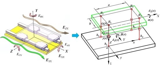
The linear motion stage suffers from various errors, such as manufacturing error, assembly error, and errors induced by force. Therefore, 5-DOF additional and unexpected error motion will appear on the stage, as shown in
Figure 1. According to ISO 230-1:2012 [
1], such geometric errors include three angular motion errors (
ECX,
EBX, and
EAX) and two straightness motion errors,
EYX and
EZX. However, in many Chinese studies, these errors are translated into “guide motion error”. The expression is not accurate; although it is related to the straightness manufacturing error of the rail itself, the guide rail itself is static, and this error is generated on the stage during its movement. Therefore, this error should be referred to as the motion error of the guide pair in Chinese studies [
2,
3].
The straightness motion error of the stage is closely related to the straightness error of the guide rail itself. Therefore, some confusion arises between these two concepts. The straightness error of the guide rail itself is a form error, which needs to be calculated and evaluated after measurement. It has a definite shape of tolerance zone, whereas the straightness motion error reflects the deviation of the stage from the ideal axis in its motion, which is not a form error and does not need to be evaluated. To obtain this deviation, we study many measurement methods and error separation techniques to improve the accuracy of machine tools or instruments by error compensation.
The straightness motion error of the linear stage is closely related to the straightness error of the guide rail itself, but these errors are different in that the guide rail straightness error is a cause, whereas the straightness motion error is an effect. Furthermore, the assembly errors, the stiffness of the base, the deformation, and the load on the stage also influenced the effect. This issue has attracted the attention of many scholars around the world, who have conducted extensive research and achieved many valuable results [
4,
5,
6,
7].
1.2. Summary of the Relationship between Slider Motion Error and Angular Motion Error
We study angular motion error because this type of error will produce an Abbe error and transmit it to the instrument or machine tool. Angular motion error is the root of the Abbe error. The Abbe principle was published in 1890. It gives us the design idea and principle needed to superficially improve the accuracy of the instrument. In essence, the influence of the angular motion error of the stage on the measurement results is eliminated through structural design [
8]. In 1979, Bryan updated the Abbe principle conception. He qualitatively expanded the relationship between the slider motion error, the angular motion error, and the straightness error of the guide rail itself. A more important contribution is that the Abbe principle was extended to the straightness motion error of the linear stage [
9]. In other words, when we deal with or analyze the error of an instrument or machine tool, the straightness motion error corresponds to Bryan’s proposal, while the angular motion error corresponds to the traditional Abbe principle [
10].
In many articles, the straightness motion error of the stage is expressed as the integration of angular motion error, or the rotational errors can be obtained reversely by differentiating straightness errors [
11,
12,
13]. A high correlation seems to be emphasized between the straightness motion error and the angular motion error. Conversely, some researchers treat them as mutually independent [
14,
15]. Ekinci depicted the relationship among straightness motion error, angular motion error, and geometric error of the guider itself, as shown in
Figure 2. In this concept, only one guider rail exists, and the carriage is supported by two linear blocks, which are abstracted as two small wheels separated by distance
L. The carriage moves on a guide rail with a geometric Δ
z(
x). Therefore, the straightness motion error
δz(
x) in the Z direction and the angular pitch error
α(
x) can be described as
Ekinci also provided a detailed analysis of this viewpoint. The accuracy of the calculation of the straightness deviation integrals from the rotation deviation depends on the ratio between the length of the guide and the wavelength deviation in the rail [
13]. Majda presented a new approach to modeling geometric errors of linear guideways for machine tools. This approach was applied by interpreting the results of experimental examinations of angular kinematic errors obtained for a real machine tool. The paper originally aimed to verify the usefulness of the concept of calculating kinematic straightness errors from angular errors, but the conclusion is that no close relationship was found between the two types of error. Moreover, straightness and angular errors on machine tools or instruments should be treated as independent of each other [
16].
In general, a great straightness error of the rail corresponds to a great straightness motion error and angular motion error of the stage. However, no direct functional relationship exists between them. When we measure and evaluate the straightness error of the guide rail by using an autocollimator or spirit level, we measure the angle error first and then convert it into displacement to construct the straightness error curve. The data processing involves accumulation and integration. This approach is the measurement method and mathematical means for evaluating the straightness error of the guide rail itself. This idea does not mean that a similar mathematical causality relationship exists between the straightness motion error and the angular motion error of the stage.
2. New Idea about Analysis of Linear Motion Error
Generally, the motion error analysis of stage is based on rigid body motion and pure geometry without considering the elasticity, stress, and deformation of involved parts in their motion. Thus, the analysis is not conducted according to the actual assembly and working conditions of the stage. If the straightness error of the guide rail itself or the manufacturing error of the related parts is large, then the intuitive phenomenon is that the stage will not move smoothly, or is even stuck, because of the increase in friction and motion resistance. When increasing the magnitude of interference between the components or generating additional elastic deformations in the relevant parts to tolerate this error, all these behaviors maintain the stage action. However, they increase friction and bring about inevitable slider motion errors. On the basis of force and moment equilibrium, and considering the deformation of the involved parts, many scholars have conducted research on the straightness error motion of the linear stage. Representative achievements are as follows.
Majda presented a new approach to modeling the geometric errors of linear guideways for machine tools, taking into consideration the strains of the table due to guideway geometric errors. This approach was used to interpret the results of experimental examinations of angular kinematic errors obtained for a real machine tool [
17]. Ohta et al. presented a flexible model that considers the flexibility of the table and rail. The calculated vertical stiffness of linear bearing using this model more closely matches the measured stiffness [
18].
The easiest way to analyze the 5-DOF motion errors is to apply finite element analysis to the entire stage under equilibrium conditions for the forces and moments. However, the model becomes cumbersome and complex for 5-DOF and is difficult to apply to various types of stages. Korean scholars also made contributions to this issue. They proposed a transfer function method to describe the characteristics of the linear motion bearing, which represents the bearing force variation of a bearing block with respect to the spatial frequency components of the rail form error. The transfer function can be used positively to predict the motion error of a table with multiple bearing blocks, in which the bearing forces are derived from the rail form error by using the transfer function [
19,
20]. The algorithm can also be used reversely to estimate the rail form error after assembly on the reference surface from the measured linear and angular motion errors [
21]. Fan et al. proposed a kinematic errors prediction method for the machine tool’s guideways based on tolerance by formulating the relationship between tolerance and geometric profile errors of guideways on the machine tools. This method is convenient for engineers to derive the distribution of kinematic errors in their design [
22]
The issue now is if we can consider the actual situation and use new ideas or theories to analyze and discuss the motion errors of the stage. During the research and development of parallel coordinate measuring machines, we found that many parallel mechanisms only have numerical solutions and cannot obtain analytical solutions. The essence of numerical solutions is to keep approaching, iterating, and then achieving convergence. In real parallel mechanism motion, the position of the moving platform is determined by the plurality of bars in common. In this process, mechanical tensile, compression, torsion, and elastic deformation of involved parts occur. When a certain position can achieve a balance among these factors, then this position is the actual position that the moving platform reaches. This process is mathematically reflected by iteration and convergence. A similar process exists in the actual motion of rail pairs [
23,
24].
In addition, due to 5-DOF additional and unexpected error motions of the stage on the linear guide pair, the corresponding angular motion errors and straightness motion errors are generated, as shown in
Figure 1. In the motion of the parallel mechanism, the moving platform also moves, with multi-DOF. The multi-DOF of real motions between them is similar. According to the linear guide pairs, the stage rides on two rails by four linear blocks. Its error motion is influenced and determined by the four linear blocks. In parallel mechanism, the position of the moving platform is also determined by the multiple branch chains, which is similar to the stage with four linear blocks.
Therefore, we attempt to abstract the structure relation of the stage and rail as a four-bar parallel mechanism. Then, the stage can be considered as a moving platform in the parallel mechanism. Its motion error analysis is also transferred to moving platform position analysis in the parallel mechanism.
3. Modeling of Stage Motion Error
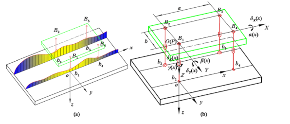
For convenience of analysis, only the straightness error of the rail itself in the Z direction will be discussed without consideration of its straightness error in the Y direction, as
Figure 3a shows. The stage rides on two rails by four linear blocks. Here, the matched pairs of blocks and rail can be simplified as a 2-RPS-2-SPS parallel mechanism, as shown in
Figure 3b. The RPS branched chain consists of a revolute pair, prismatic pair and spherical joint. The SPS branched chain consists of a spherical joint, prismatic pair and spherical joint. The linear deviation of the rail in the Z direction is considered as the variation in rod length in the parallel mechanism.
According to the modified Kutzhach–Grubler formula of degree of freedom, the degree of freedom of the 2-RPS-2-SPS parallel mechanism can be obtained
where
M is the degree of freedom of the mechanism,
n is the total number of components,
g is the number of motion pairs,
fi is the degree of freedom of the
i-th motion pair. There is a local degree of freedom of rotating around its axis between the two ball hinges at the SPS branch chain, and local degree of freedom
ε = 2. The 2-RPS branch chains and 2-SPS branch chains are set along the X-axis, respectively, presenting a partial symmetrical structure that means parallel mechanism has four degrees of freedom including α(
x) rotation around the Y-axis,
β(
x) around the X-axis (we usually refer to them as pitch and roll), and the
δz(
x) and
δx(
x) movements along the Z and
X-axes shown in
Figure 3b.
From the perspective of parallel mechanism, the base plane where the two rails sit is the static platform. The stage can be taken as a moving platform. They are connected by two RPS branch chains and two SPS branch chains. The linear deviation of the rail in the Z direction is considered as the variation in the length of branch chains in the 2-RPS-2-SPS parallel mechanism,
L1–
L4 are the length of the branch chain shown in
Figure 3b [
25].
Taking the joint center point B1 on the moving platform as the coordinate origin, the moving coordinate system O-XYZ is established and the XOY plane is parallel to the installation plane of the two guide rails. The static coordinate system o-xoy is established by taking the joint center point b1 in each pose as the coordinate origin. The xoy plane is also parallel to the installation plane of the two guide rails.
bi = (
bxi, byi, bzi)
T is the coordinate vector of the joint center point in the static coordinate system o-xyz;
Bi = (
BXi,
BYi,
BZi)
T represents the coordinate vector of each joint center point at the moving platform in the moving coordinate system O-XYZ, and
X = (
xp,
yp,
zp)
T is the coordinate vector of the origin point of the moving coordinate system in the static coordinate system. The coordinates of every joint center points are shown in
Table 1,
i = 1, 2, 3, 4.
a = 140 mm,
b = 100 mm in the self-developed parallel coordinate measuring machine.
Since this parallel mechanism did not consider the rotation around the Z-axis, the pose transformation matrix
R can be simplified as
Therefore, by coordinate transformation, the vector
Bi on the moving platform is transformed into the static coordinate system o-xyz, which can be expressed as
CiLength vector
Li can be expressed as
where
li= (
lix,
liy,
liz)
T, and the length of the top and lower joint of branched chain
li is
Since this parallel mechanism did not consider the translational motion in the the Y-axis,
yp = 0, substituting the coordinate values of each joint into Equation (6), the following formula can be obtained
After the parallel mechanism structure parameters are identified, the length of the branch chain contains all the information about the pose and position. Thus, on the basis of the length change in the rod, the original position is selected to obtain the inverse motion position variables. Then, the length of rod numerical in different pose and position are integrated into the forward solution model of the parallel mechanism, and the fsolve function in MATLAB is used to iterate the nonlinear function groups to gradually approach the real length of the rod. First, the original position of the moving platform is assumed as (
xp0,
zp0,
α0,
β0). Through the analysis of inverse kinematics position, the posture of rod length
Li1 is obtained. The length of the rod is as
Li, and the difference between
Li1 and
Li is Δ
Li1 =
Li −
Li1.
Li is the position variable function (
xp,
zp,
α,
β) of the moving platform. It can be obtained as
where Δ
Li(1) is the first-time length-modified increment, and (Δ
xp(1), Δ
zp(1), Δ
α(1), Δ
β(1))
T is the position-fixed increment for the first time. The first fixed position of the moving platform can be rewritten as
Then, the first-time fixed position of the moving platform is taken as the initial value to iterate again, with the process repeated n times until the expected accuracy is reached. The position (xpn, zpn, αn, βn)T, at this point, is the actual position under the length of rod Li and is also the expected result.
4. Experiment and Data Analysis
Figure 4 shows the straightness of two long rails (2000 mm) in the Z direction is measured on a self-developed 3-PUU parallel CMM by using the traditional autocollimator. The experiment was carried out at a temperature of 20 ± 1 °C. The autocollimator (model: JJ-99 from Jingda Measurement Technology Co. Ltd. Jiujiang, China) is used. The measuring range is ±10 s and the resolution is 0.1 s. The straightness error curves of the two rails after the original data processing are shown in
Figure 5 [
26].
In accordance with the above straightness error of two rails in
Figure 5, the least square method is used to fit the straightness deviation equation for the two rails in the Z direction along the X-axis [
26]
Thirteen center positions of the stage are selected for simulation calculation with 150 mm spacing,
x = 75, 225, 375, 450, ⋯525, ⋯1875. With the use of Equation (8), values of straightness on four points
b1,
b2,
b3,
b4 can be obtained, taking them as the variation in rod length into the above model of the parallel mechanism. The iteration results obtained by using the fsolve function in MATLAB are shown in
Table 2 [
26].
In the third column of
Table 2, the value of Δ
X is the additional motion error in the X direction caused by the straightness error of the guide rail. This result is different from
EXX Figure 1, which is generally called the positioning error along the moving axis. Generally, we always consider that the positioning error is mainly determined by the driving system and controlling system. Here, we found that the straightness error of rails will also provide an additional motion error to the X-axis and contribute to the total position error
δx(
x).
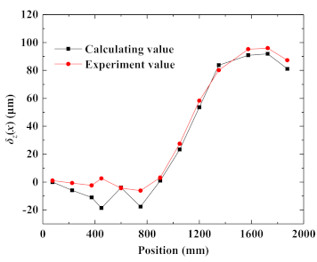
The fourth column in
Table 2 shows the calculation result of
δz(
x); its variation curve is shown by the red line in
Figure 6. The black curve in
Figure 6 is the straightness motion error of the center on the stage in the Z direction, measured directly by the laser interferometer (model: XL80 from Renishaw Co. Ltd. London, UK); the experiment was carried out at the temperature of 20 ± 1 °C [
27]. By comparing the two curves, we can see that the two curves basically coincide, which means the above analysis is a feasible method.
We also compare the calculated pitch angle in the fifth column with the actual pitch error measured by the autocollimator. The comparison results are shown in
Figure 7, and their variation tendency is similar. The data of the roll angle were not compared because measuring the roll angle by using the autocollimator is inconvenient. We will continue this work in the near future.


